We bought a replacement for the CorningWare casserole (that a raccoon broke when I put the rice out on the deck to cool) at a tag sale:

According to the information on the bottom, it’s “Nouveau A Princess House Exclusive” that’s no longer in their listing. Evidently, they’ve gone to metal stovetop cookware these days. Anyhow, it has a separate handle that latches onto a cleverly shaped tab molded into the pan:

Latching the handle in place is simple: put the end of the handle over the tab and squeeze the lever until it snaps into the handle. Well, I managed to latch it quite easily, after which nobody could figure out how to release it. That slotted button cries out to be pushed, but it wasn’t push-able.
That’s a condition I call “being outwitted by inanimate objects”…
After bringing it home, I discovered the secret: the slot must be exactly vertical (equivalently, maximally counter-clockwise) before you can press the button to release the latching handle. Turning the button so the slot is horizontal (maximally clockwise) locks the button out, so that you cannot press it and release the handle:
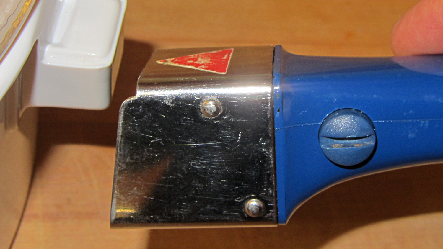
The button locks out when the slot is almost imperceptibly clockwise from vertical; if you don’t know what to look for, you’d never notice the difference.
Which makes perfect sense to me. You want the handle to latch securely and require a deliberate action to release, lest the pan fall and release hot stuff all over your front. Any errors should leave the handle securely latched in place.
FWIW, World Kitchen, the current owners of the CorningWare brand, no longer make stovetop-rated ceramic cookware; it’s evidently easier and cheaper to make microwave-only ceramics. World Kitchen also owns the Pyrex kitchenware brand and, true to form, replaced the original borosilicate glass with cheaper tempered soda lime glass. Sic transit gloria mundi and all that…