Mary picked up a pair of Star quilting rulers from the Quilting Guild’s “exchange” table:
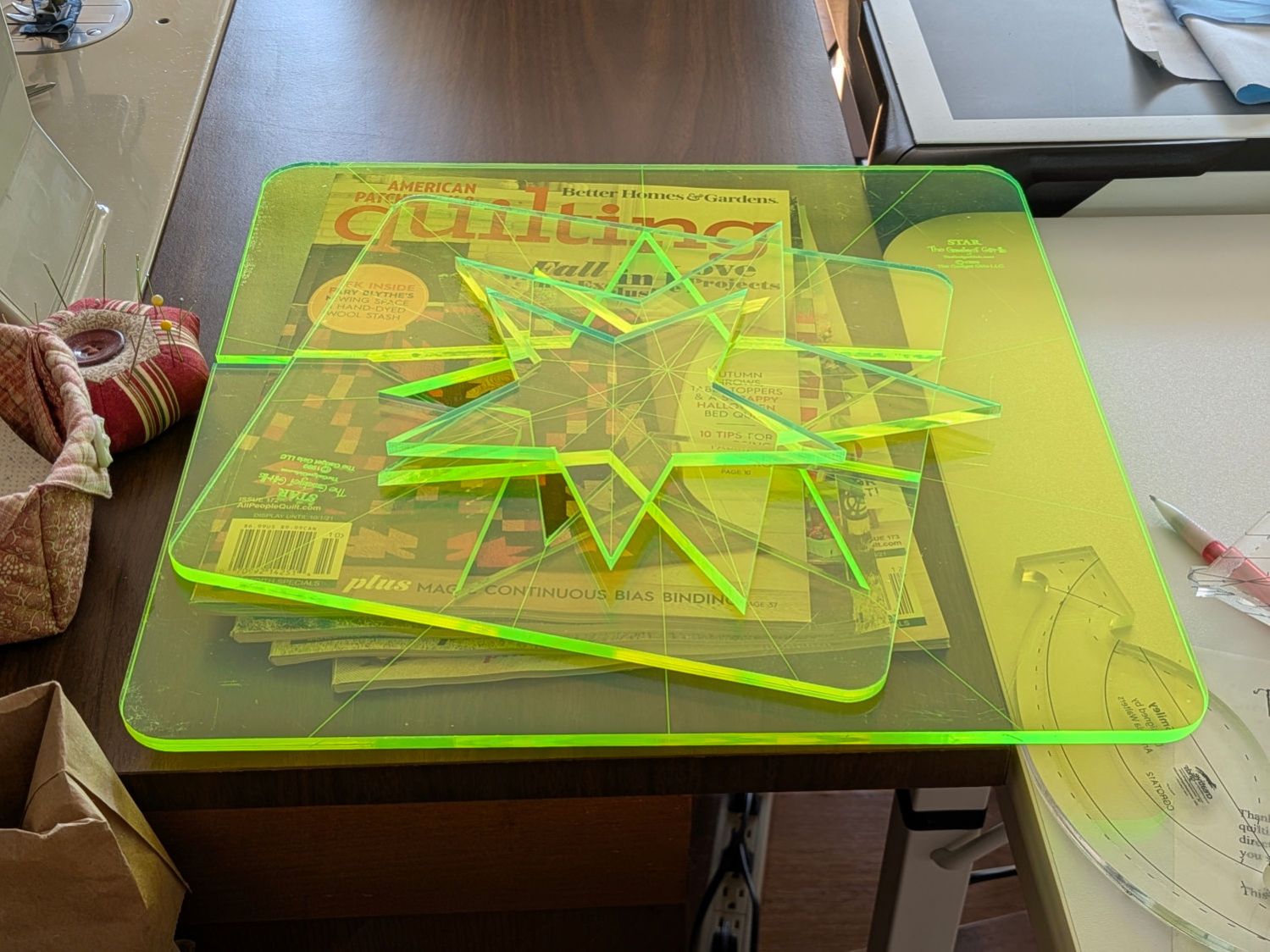
They’re 1/4 inch laser-cut acrylic slabs dating back to the turn of the millennium, when laser cuttery wasn’t nearly as common as today. Apparently, the (now long gone) Gadget Girls had a problem with their laser: the larger star had eight of its ten lines not cut completely through the acrylic. The protective paper on the back had small perforations along a few of the lines, but nothing for most of them.
Well, I can fix that.
Lay the slab on the platform and lock it in place so it cannot move:
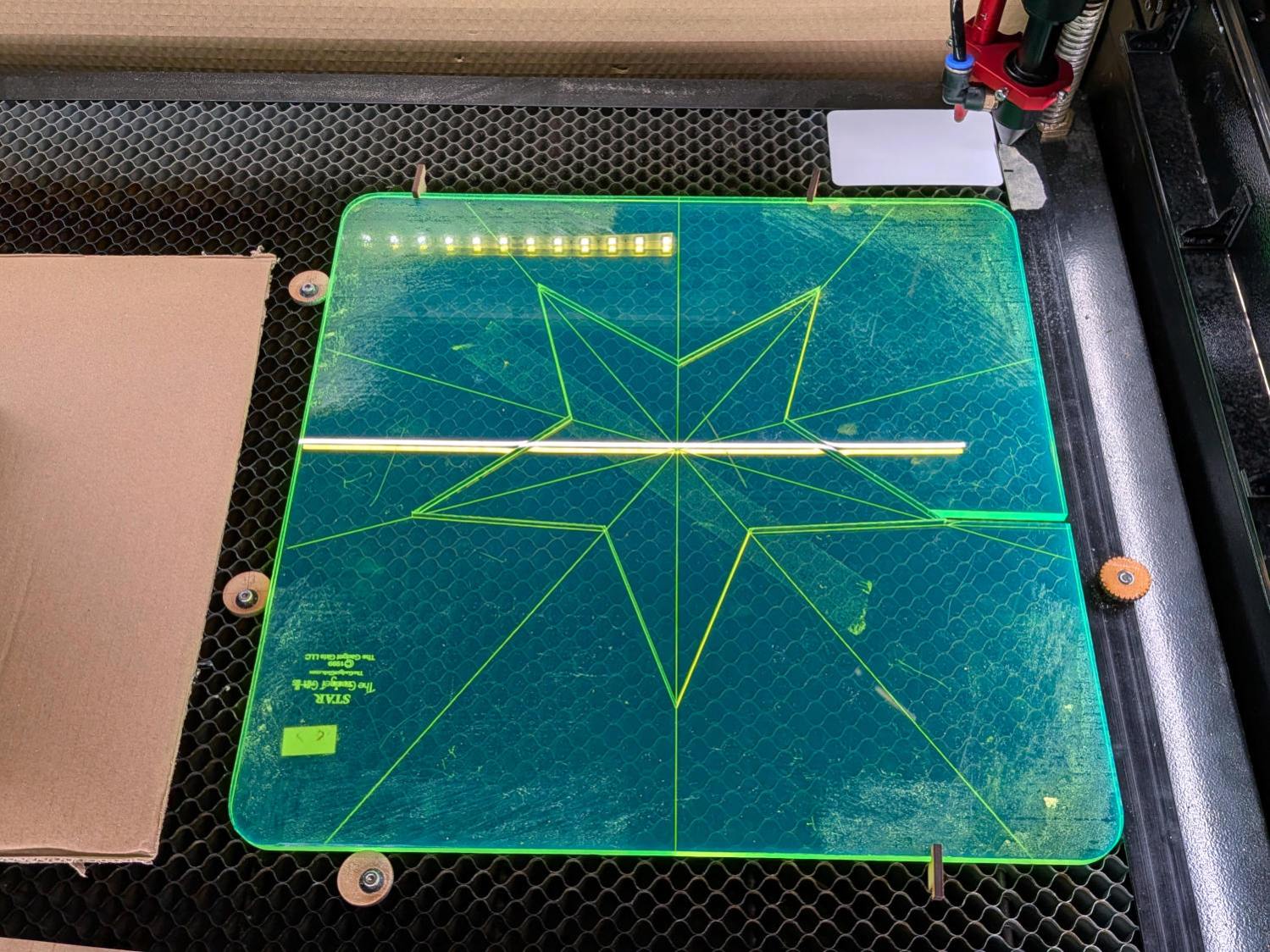
That’s with the original bottom side facing upward, so the laser beam will hit the uncut part of the lines.
Focus the laser atop some scrap 1/4 inch acrylic, then verify the red dot pointer is exactly concentric with the CO₂ beam by firing a test pulse, as in this punched card:
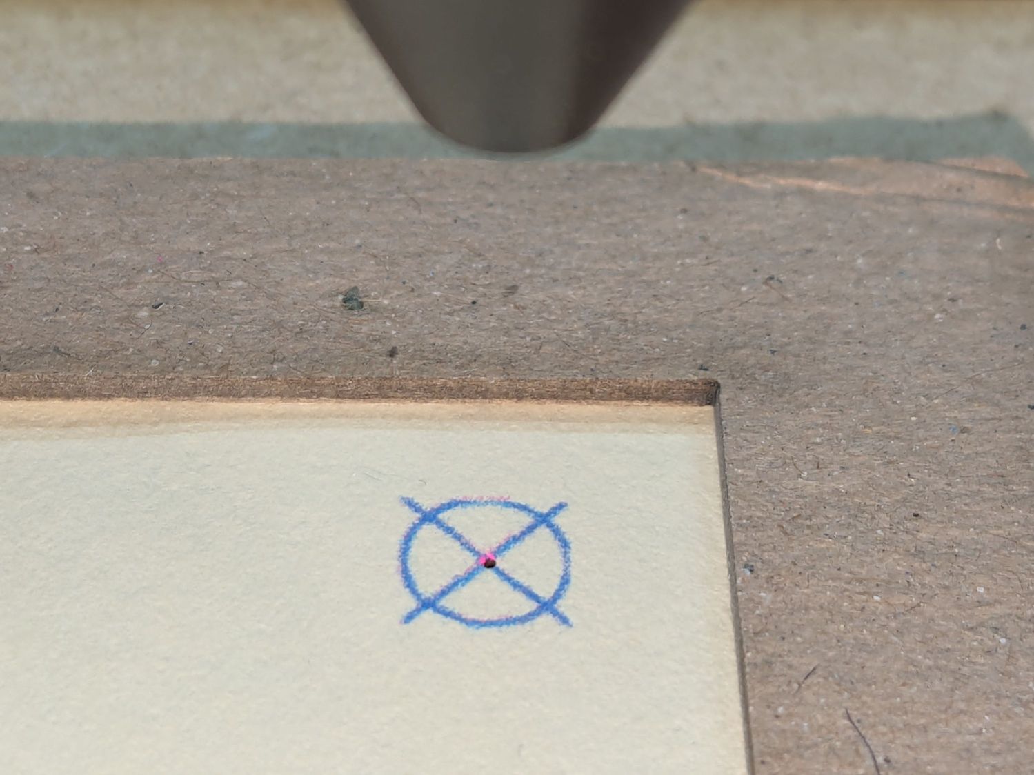
Adjust as needed.
Jog the laser to put the red dot pointer exactly at a star point:

Hit Get Position in the Laser window so LightBurn knows where the laser head is located.
I’ve added the targets I normally use for LightBurn’s Print and Cut alignment to its Art Library, so I dragged one to the workspace, then hit Move to Laser Position to snap the target directly onto that point of the star.
Repeat for vertices along the star, then draw a multi-segment line = path between the target centers:
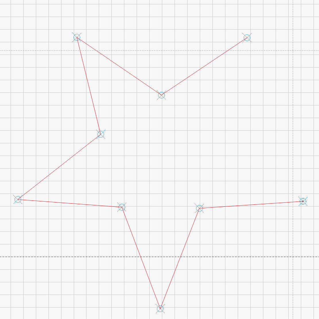
That’s one continuous path from the upper right, counterclockwise around the star, ending in the center right. The missing pair of lines (and the vertex between them) were already cut, so I didn’t need to locate them.
The camera view shows the alignment, although IMO the camera simply isn’t capable of such finicky alignment:
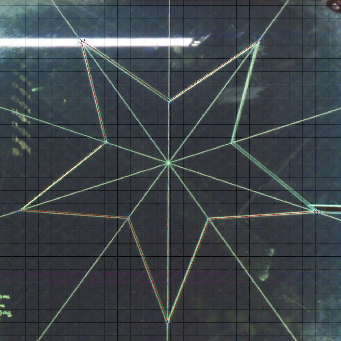
As a confidence builder, I selected each target, moved the laser to that point, then fired a test pulse to verify the hole hit the vertex. In most cases, I couldn’t see the hole because it was within the original cut.
My 60 W laser can’t cut through 1/4 inch = 6 mm acrylic in a single pass, so I use a 10 mm/s @ 60% pass to get most of the way through and a 20 mm/s @ 60% pass to complete the cut. That seemed excessive for a mostly cut path, but a single 20 mm/s @ 60% pass didn’t completely clear the uncut sections.
So I used the normal two-pass cut and the star lifted right out:
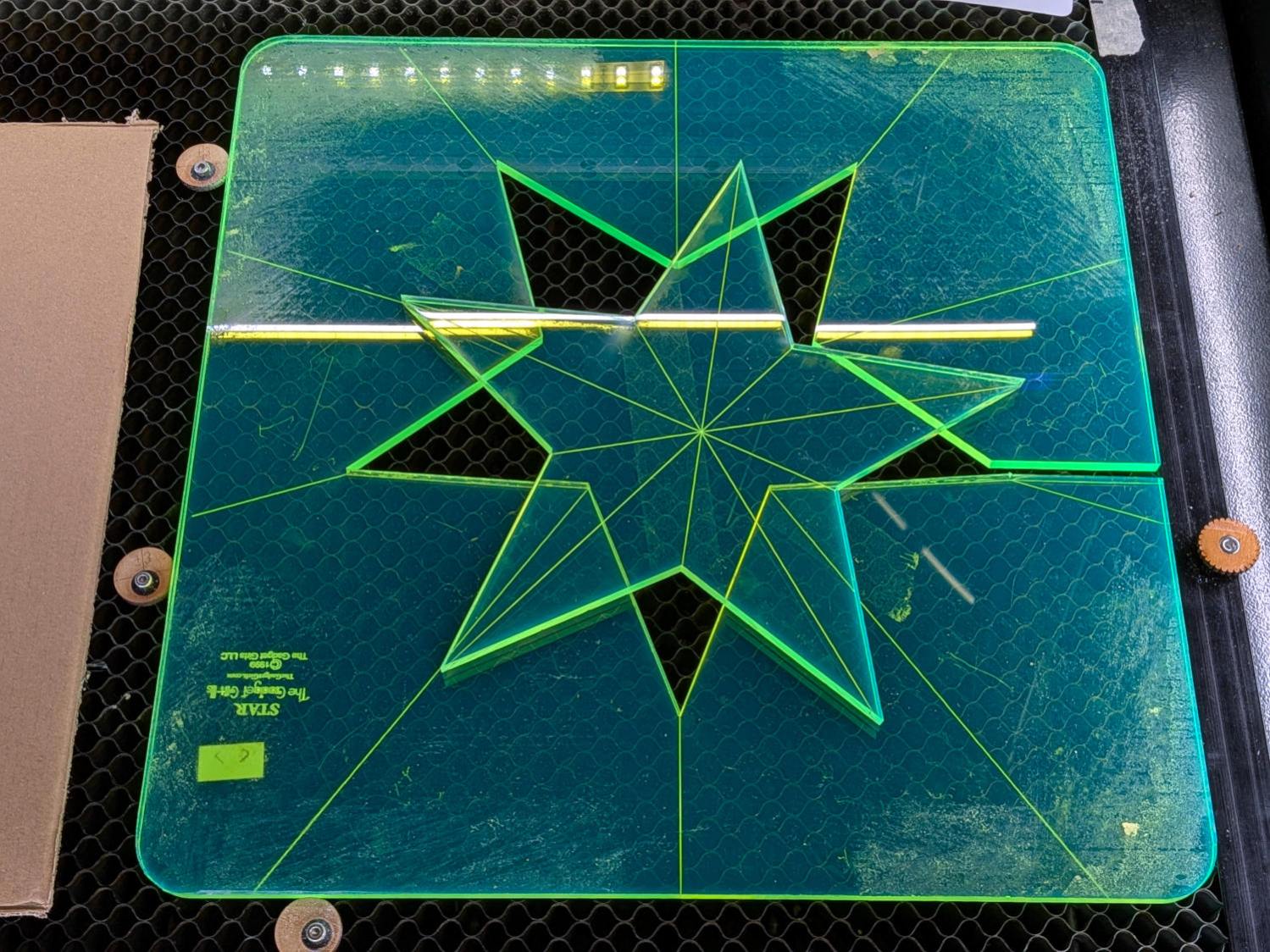
Happy dance!
Although it is not obvious from the pictures, the star is not symmetric: it fits into the sheet in only one of its ten possible orientations. I will never know if that was a deliberate stylin’ decision or the result of hand layout before CAD spread throughout the land.
I managed to locate the vertices so accurately that the repeated cuts left edges indistinguishable from the original cuts on the two free sides, which was a pleasant surprise.
Mary promises to do something with those stars when she’s done with her current project(s). She may want the slab of acrylic around the large star trimmed into a smaller and more manageable decagon, in which case I will suddenly have a bounty of thick fluorescent green acrylic.