Ed Nisley's Blog: Shop notes, electronics, firmware, machinery, 3D printing, laser cuttery, and curiosities. Contents: 100% human thinking, 0% AI slop.
They’re all 01 size pens, with a nominal 0.25 mm line.
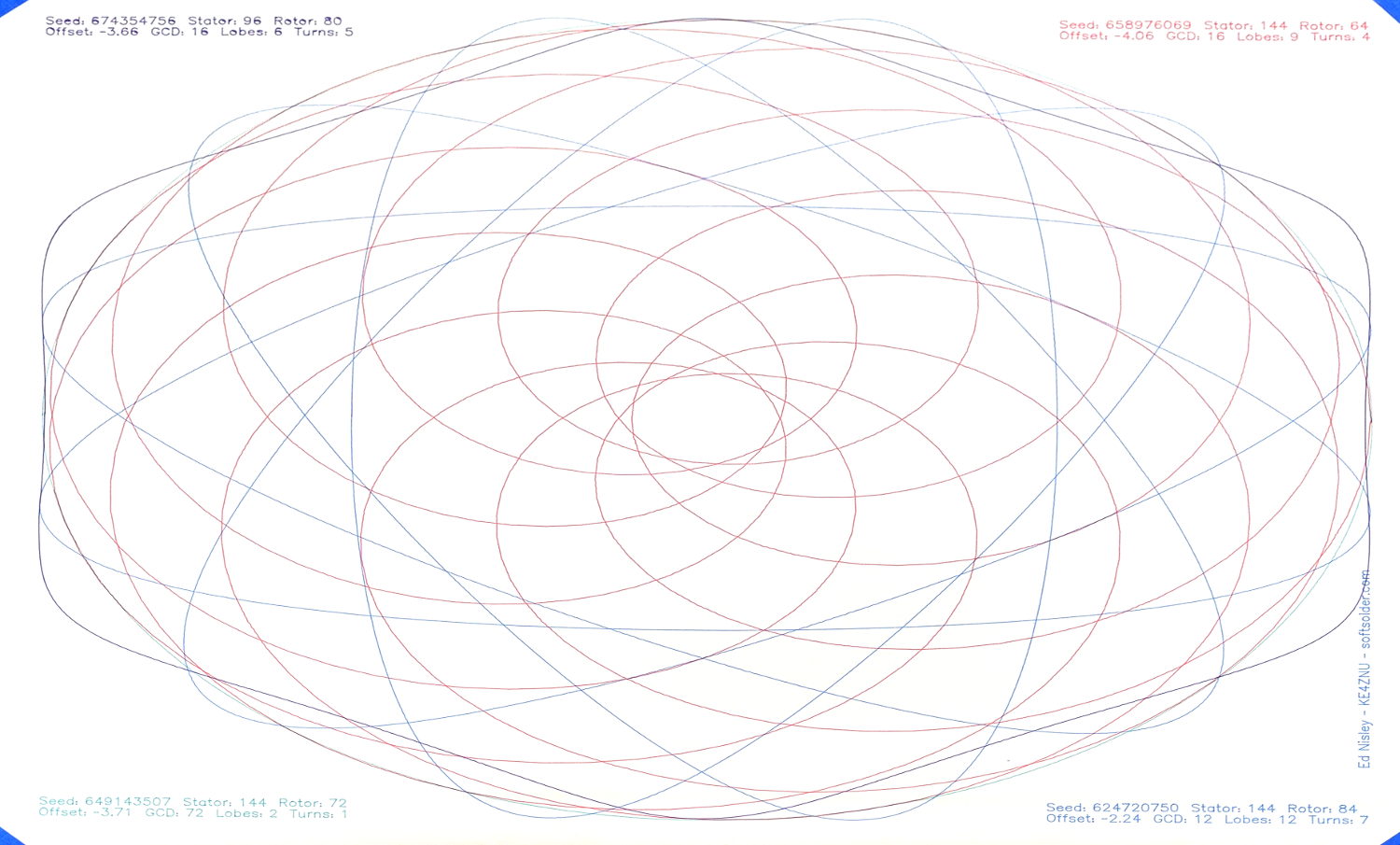
Just for fun, a plot done with four sizes of black Sakura pens at Z=-1.0 before the Great Leveling:
MPCNC – Sakura Micron black pen widths
The 005 pen made a nearly rectangular single-pass tour around the perimeter of the plot, so you’ll see it passing through every legend.
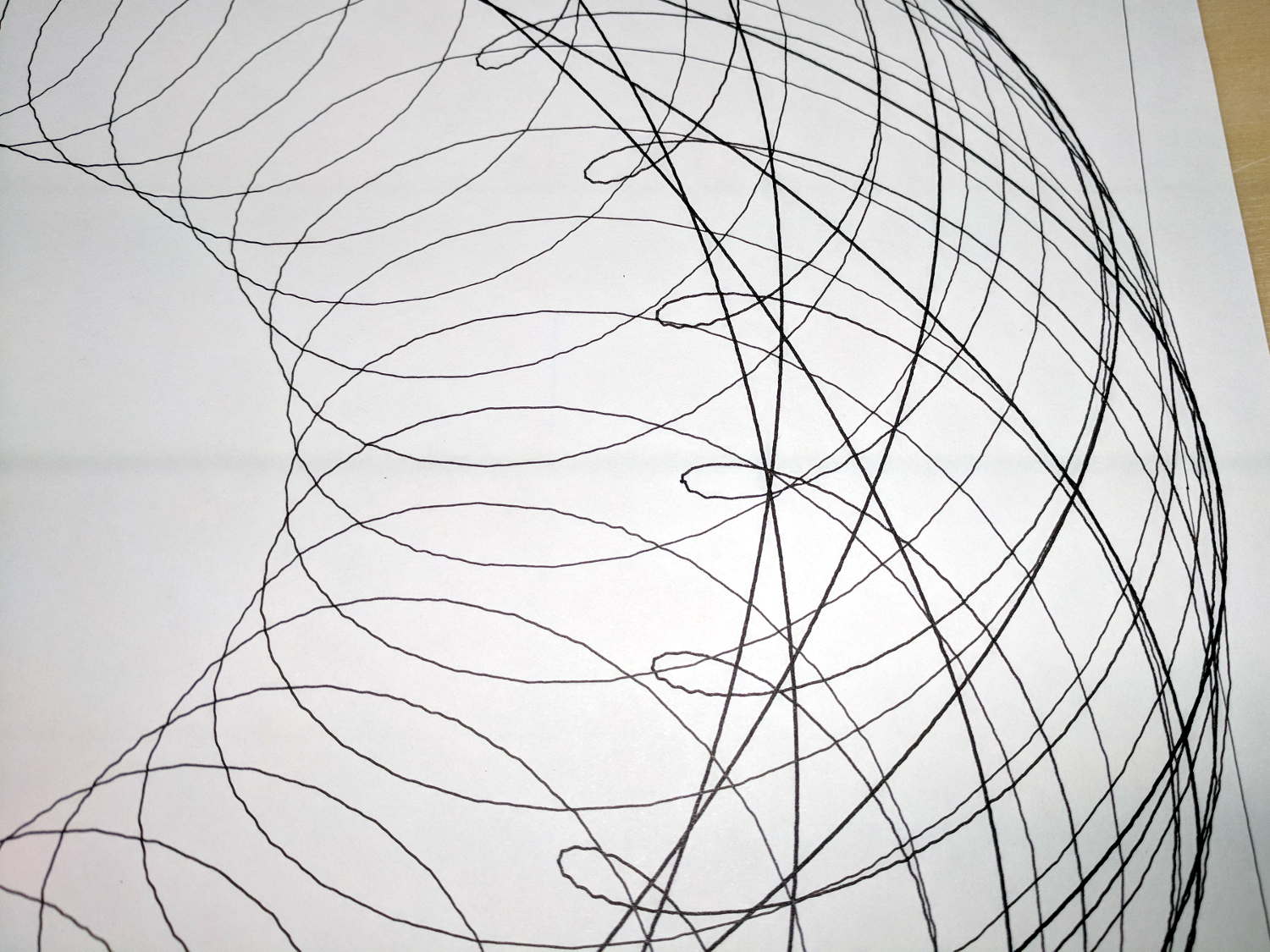
The chunky-by-comparison 08 pen = 0.50 mm:
MPCNC – Sakura Micron 08 Black – detail
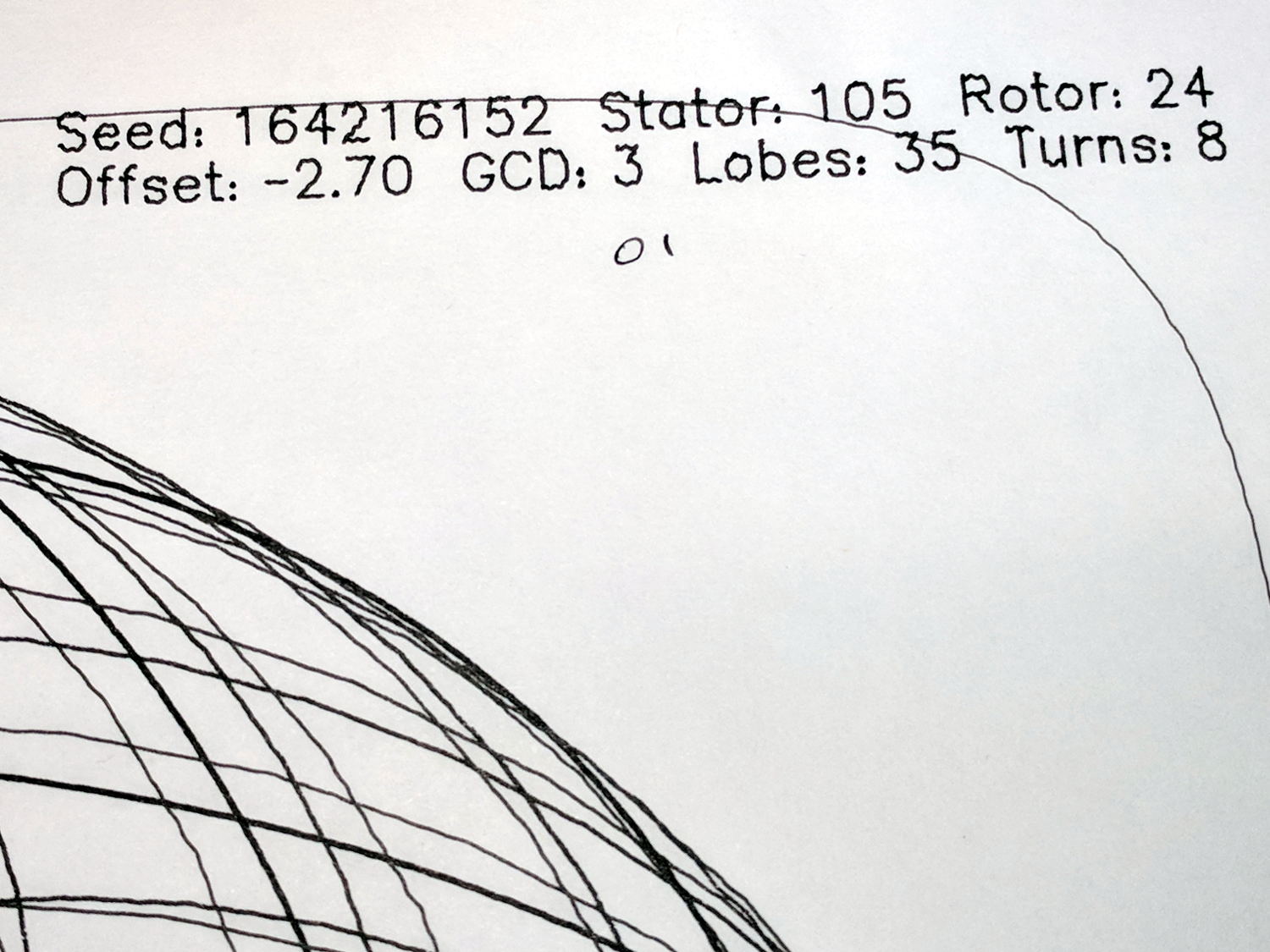
The 05 pen = 0.45 mm looks much crisper:
MPCNC – Sakura Micron 05 Black – detail
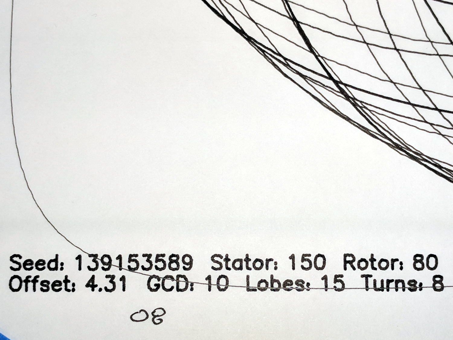
The 01 pen = 0.25 mm:
MPCNC – Sakura Micron 01 Black – detail
The almost-can’t-see-it 005 pen = 0.20 mm:
MPCNC – Sakura Micron 005 Black – detail
If you were doing this for a living, you’d probably use 05 pens, because plotter pens are hard to find.
Original HP plotter pens produced a 0.3 mm trace (with a hard to find un-worn tip) roughly equal to Sakura 03 pens, but I haven’t seen anything other than black at Amazon. There’s apparently a 003 pen with a 0.15 mm line; that’s just crazy talk.
Jamming Sakura pens into a plotter pen adapter for the MPCNC makes little sense, so I should gimmick up a specialized holder with some thumbscrew action to keep them from crawling upward out of the holder.
The numbers inside the lower square give the additional height required to sorta-kinda level the result, keeping in mind we’re not dealing with a particularly stable mechanical setup.
The figures in the lower right translate sensible metric values into mils. I plucked those sheets from my brass shimstock selection, taped them together into a 42 mil stack, and introduced them to Mr Bandsaw:
Sawing MPCNC Corner Post Shims
The sacrificial sheet underneath the stack prevents bending. Using the saw (with a 24 tpi blade), rather than tin snips or scissors, produces a nice clean flat cut without any curling or bending.
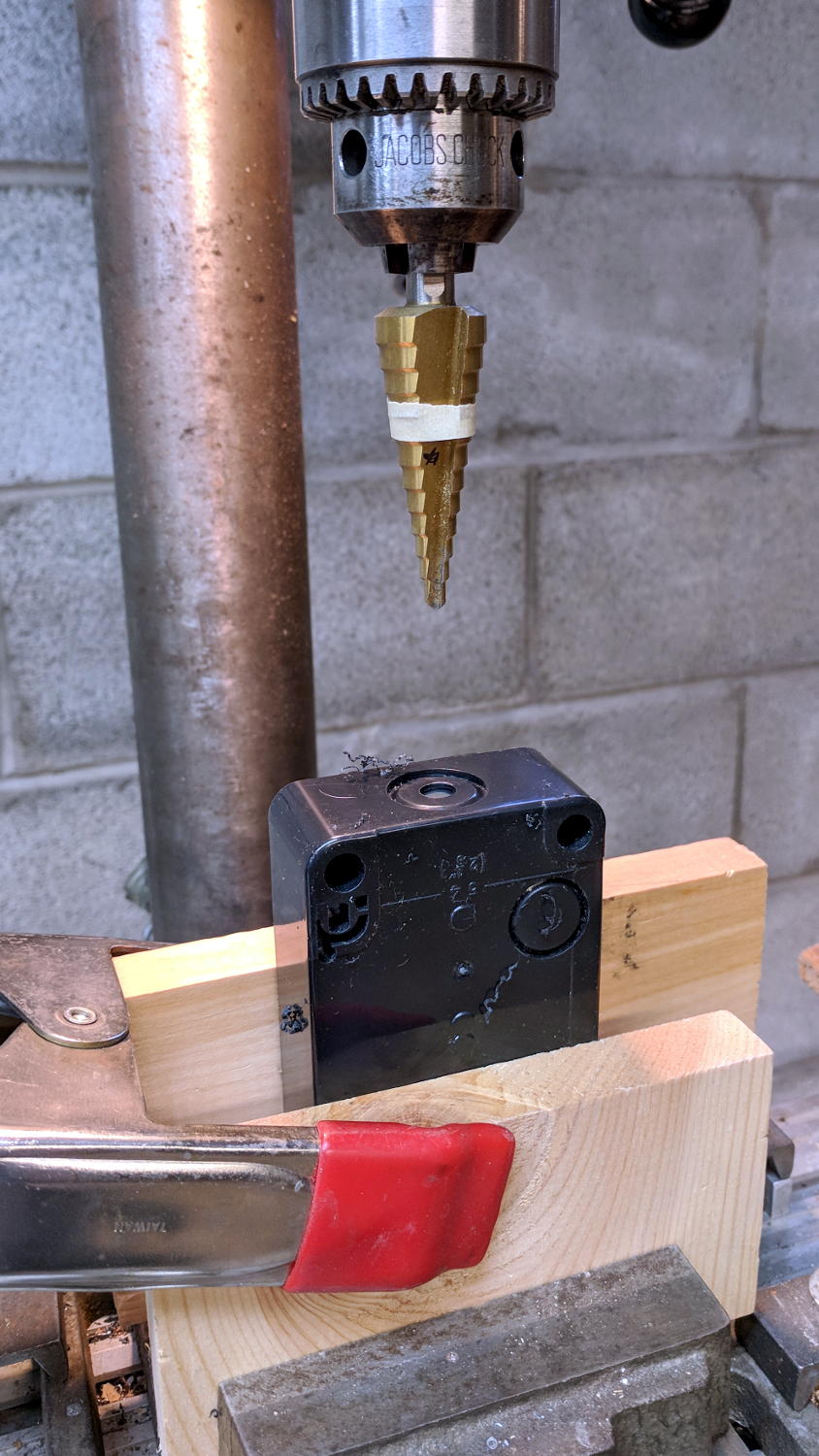
A brief conversation with Mr Drill Press created screw clearance holes:
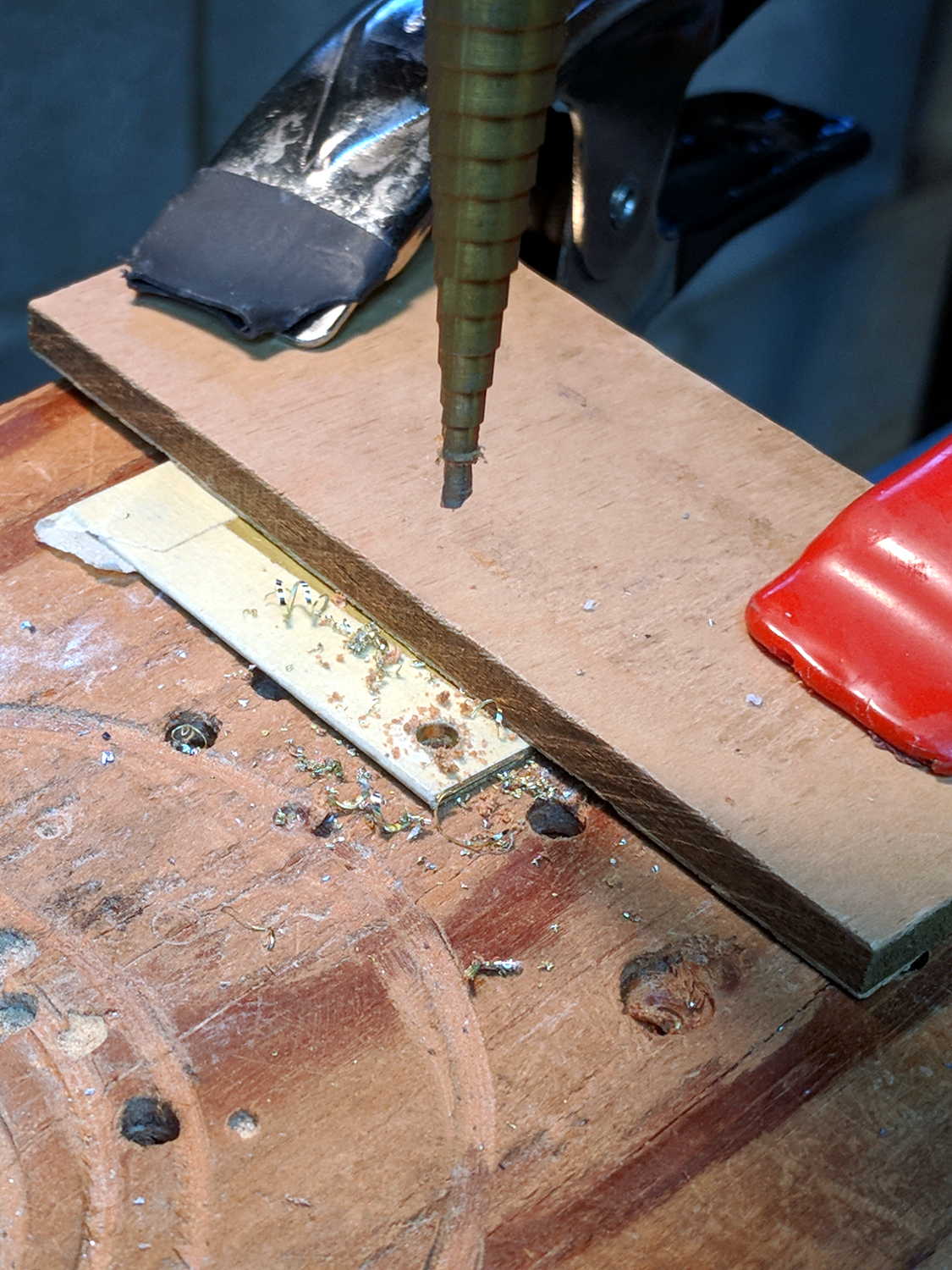
Drilling MPCNC Corner Post Shims
N.B.: Brass is fiercely grabby, so don’t use an ordinary twist drill. Blunt ’em if you have a spare set of drills, but a step drill works for my simple needs, shallow holes, and infrequent drilling. In any event, don’t hand-hold the sheets, because they can turn into whirling knives without the formality of warning you first.
I bandsawed the holes into slots, so I could slide the shims under the corner posts without completely removing the screws, in the hope the posts would stay more-or-less in the same place. Probably doesn’t make any difference:
MPCNC Corner Post Shim
Looks like I overtightened the post clamp screw a bit, doesn’t it? So it goes with 3D printed parts.
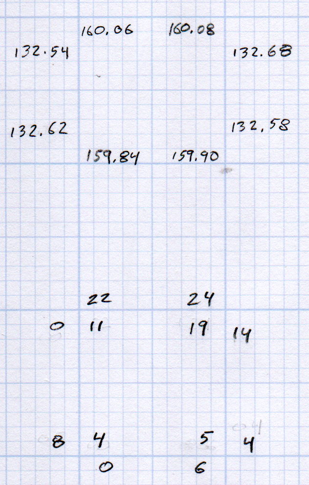
Another round of measurements with the shims in place:
MPCNC Rail Height – 2017-12-25
The numbers on the outside of the bottom set give the difference from the lowest rail in each direction, the inner numbers are the average of the two differences in each corner.
All of which seems to indicate the pen height now varies by a smidge over 0.1 mm across the span of those 16.5×14 inch plots.
A plot with all the legends and traces at Z=-0.25 came out OK:
MPCNC – Leveled plot at Z -0.1
The legend in the upper left looked slightly faint:
MPCNC – Leveled plot at Z -0.1 – legend detail
The upper right legend looks about the same, suggesting my average of differences probably isn’t meaningful.
Lowering the pen to Z=-0.25 should darken the traces a bit and reduce the effect of any inconsistencies in the tool length probe switch.
Not, of course, that this will make much difference in actual use; a router will probably shake the whole thing out of alignment in a matter of seconds.
After once again figuring out how to read a vernier height gage, I measured the height of each end of the MPCNC rails:
Brown and Sharpe 585 Height Gage
The process:
Position the gage near the end of the gantry’s travel
Twiddle the knurled ring to lower the probe (a.k.a. lathe bit) until …
It firmly captures the paper slip, then …
Twiddle the ring the other way until …
The paper barely moves
Read the vernier and take a picture
So the numbers come out one paper thickness higher than the actual rail height; subtract 0.1 mm = 4 mil to get the true height:
MPCNC Rail Height – 2017-12-23
In round numbers, the difference is under 0.3 mm along each rail.
The outer numbers on the lower sketch show the difference between each reading and the lowest value along that axis: the left rear corner is (roughly) 0.5 mm higher than the right front. The numbers inside the square give the additional height, rounded to sensible values, required to raise the low corners.
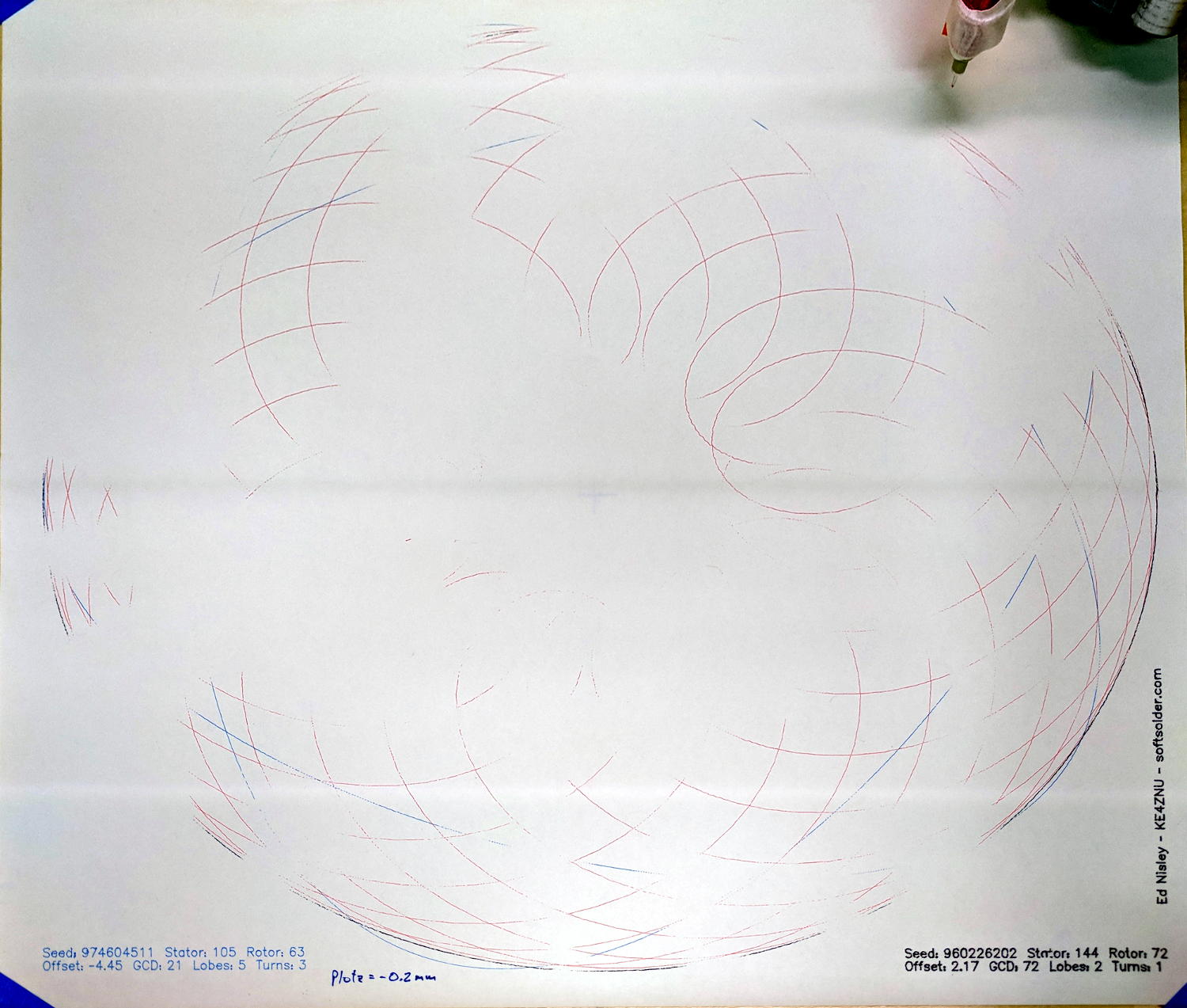
Which means you can’t plot at, say, Z=-0.2 mm to reduce the pen loading, because the pen doesn’t uniformly touch the paper across the entire plot:
MPCNC – Unlevel Z -0.2 plot
These images have been perspective & aspect ratio corrected, then ruthlessly contrast-stretched to make the traces visible; the lighting isn’t that awful in person!
With the plot at Z=-0.2, the legends toward the front came out OK, but they’re missing along the far edge. The Spirograph traces go completely missing toward the left rear as the pen rises away from the paper, although I think we’re also seeing some ripples in the paper sheet.
Although such a small error probably makes no difference to a wood router, let’s see what we can do.
Manually editing the G-Code to put successive traces at 0.1 mm increments from Z=-0.3 to Z=-0.6 mm, then replotting on the same piece of paper, shows the problem a bit better:
MPCNC – Unlevel plot – multiple Z
All of the legends remain at Z=-0.2, because I wasn’t up for editing every pen-down command.
Even at Z=-0.6 mm, the pen doesn’t quite touch in the left rear corner. Previously, I’d been plotting at a nice, round Z=-1.0 mm, which worked fine. I didn’t run any tests below Z=-0.6, but I think Z=-0.8 would draw a complete plot.
That agrees reasonably well with the height gage measurements.
It’s obviously impossible to re-level the rails by dinking around with the corner post lengths, because I can’t move the EMT in precise increments and it’d never stay in that position anyway. Instead, I should slide shims under the three lowest corner feet to raise them enough to match the left rear corner.
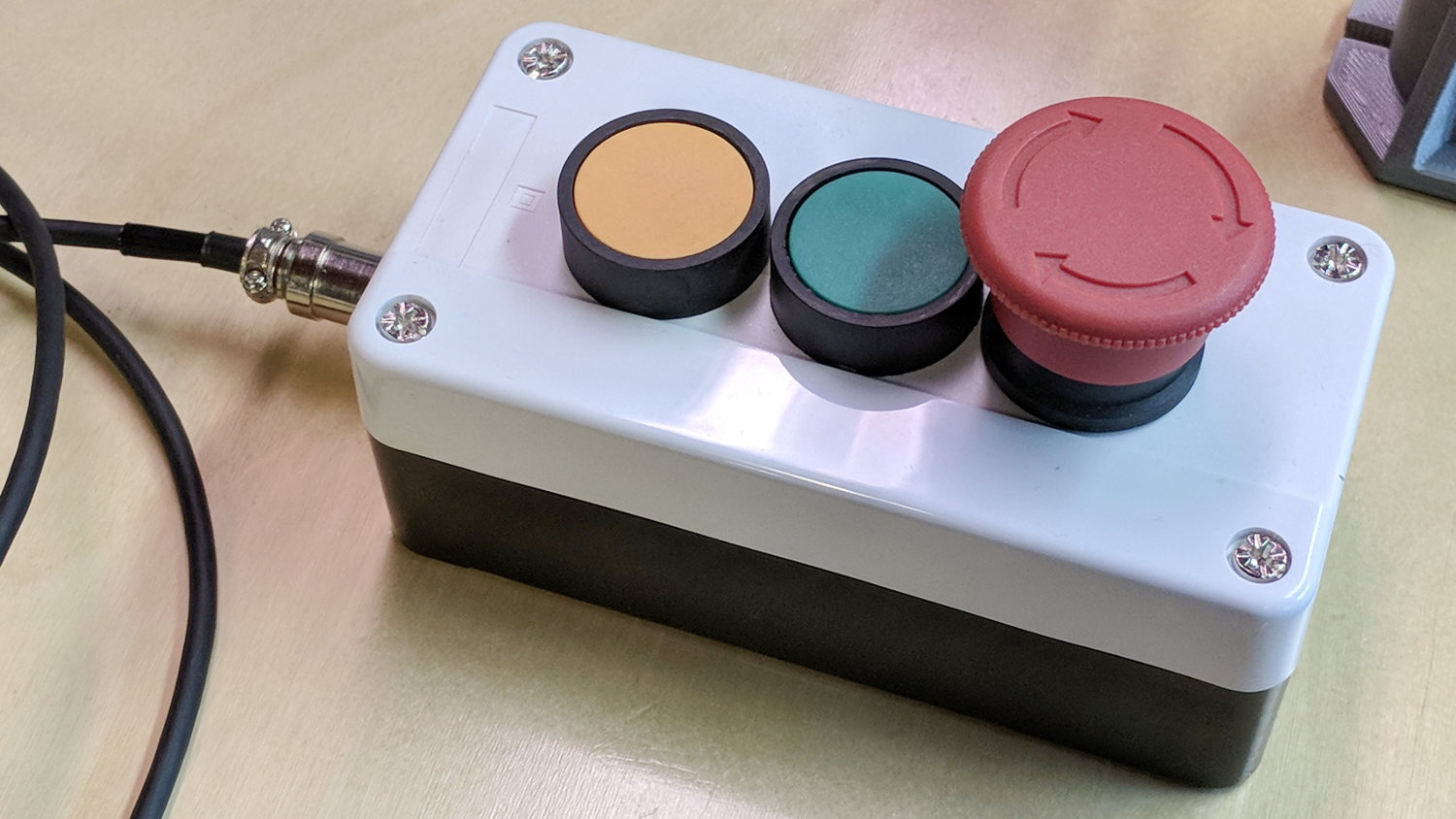
The Protoneer CNC Shield has pin headers for GRBL’s Feed Hold and Resume inputs, so it seemed appropriate to put big buttons on the far end of the cable:
You could CNC machine a precise D-hole, but let’s stay realistic about the application. Applying a deburring tool enlarged the 9/16 inch hole enough to force the 16 mm threads into it, with the drill press holding the connector perpendicular to the box while I hand-turned the chuck to screw it in.
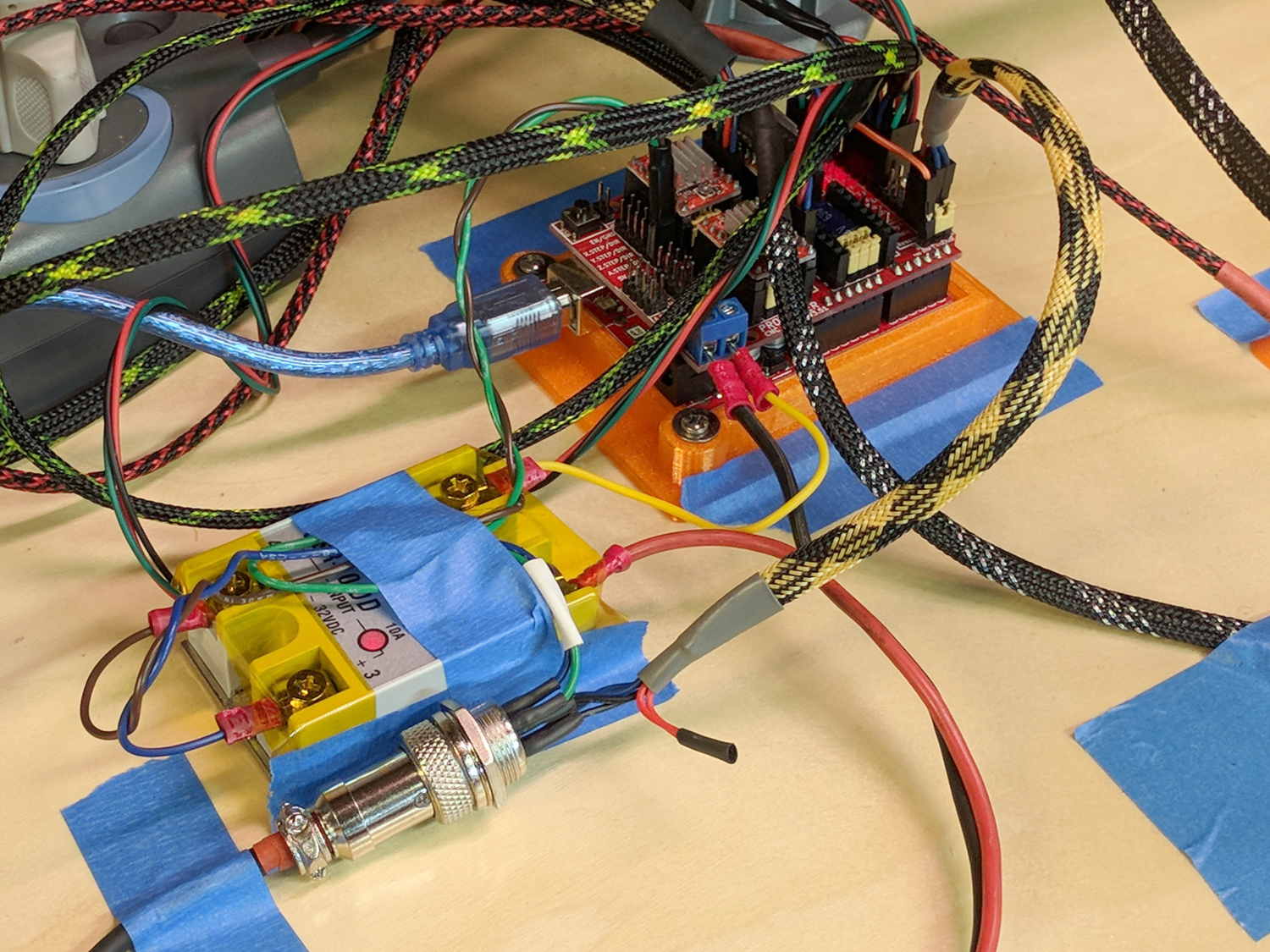
Although I like the Protoneer CNC Shield, I really really dislike using header pins as connectors:
MPCNC – Protoneer Wiring – SSR
Those pins are much too delicate.
The DC-DC solid state relay input connects to the Arduino’s +5 V power supply through the red mushroom disconnect switch. The mushroom is normally closed to turn on the SSR and connect the power brick’s +24 V supply to the motors; it opens when slapped. GRBL will continue about its business, but without any power to the steppers the MPCNC will stop dead in its tracks. Turn the mushroom cap clockwise to unlatch and reset.
The disconnect switch should also kill AC power to the router, when I get around to adding one to the mix, probably through a DC-AC SSR.
AFAICT, the cable should come out of the box on the end with the mushroom switch, putting the “normal” pushbuttons closer to me. I did it the other way around, because I want the panic button to be the most easily reached thing on the benchtop. If I have time to think about it, I can reach around the mushroom to the Hold switch.
The first time around, I simply set both pairs of MPCNC rails to equal heights using my height gage (*) as a reference, rather than as a measurement tool:
MPCNC – Rail height measurement
By now, I assume all the plastic bits have shaken themselves down and the rails have settled into their more-or-less permanent locations, so it’d be useful to measure the actual rail heights and adjust as needed. The scale along the vertical bar of the height gage gives the height of the top surface of the projecting arm above the bench:
Brown and Sharpe 585 Height Gage
Normally, the gage base would sit on a surface plate. Building an MPCNC on a big granite slab would certainly cut down on the shakes from overly enthusiastic acceleration settings!
The nicely reshaped and polished lathe bit transfers the top surface of the gage arm to the top of the MPCNC rail, so whatever height shows up on the vernier gives the rail height. The exact value, of course, doesn’t really matter in this situation, but when you need an actual measurement, it’s got you covered.
The two brackets slide along the height gage, with the thumbscrews on the right locking them in position. To measure a height, you loosen both thumbscrews, slide the whole affair to put the arm bracket at about the right height, tighten the top thumbscrew to anchor the adjusting bracket, twirl the knurled wheel to precisely position the arm bracket, then read the height from the scale.
The other scale on the other side has inches, but nobody uses those any more. Right?
Things I didn’t get quite right the first time around:
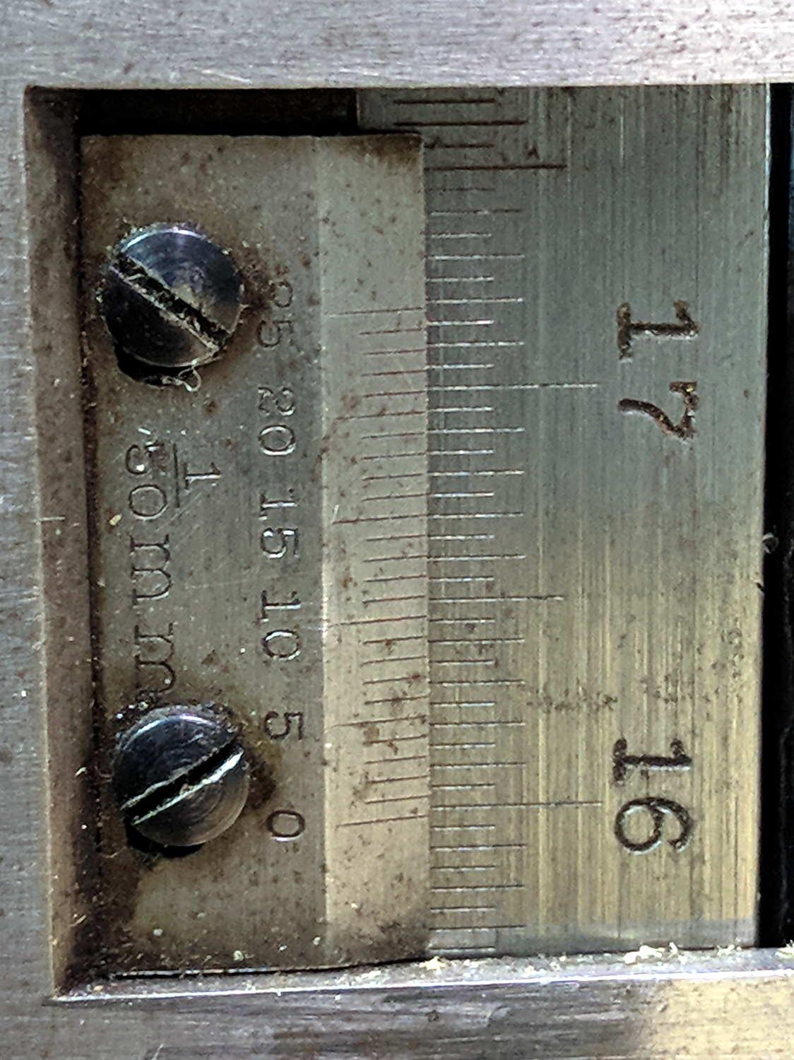
The numbers along the right side are in centimeters
The smallest lines on that scale mark 0.5 mm increments
The numbers on the vernier have units of 1/50 mm = 0.02 mm
So, to read the scale:
Multiply centimeters by 10 to get millimeters: 130
Add the number of whole millimeters below the 0 vernier index: 2
Add a half millimeter if needed: 0
Find the matching vernier increment: 10
Multiply the increment by 2: 20
Slap the decimal point two places left and add: 132.20
OK, try this one:
Vernier Height Gage – 159.84 mm
As I see it:
Read 15 cm
Count 9 ticks
Add the 0.5 mm tick
Match vernier tick 17, multiply and slap decimal = 0.34 mm
Add: 150 + 9 + 0.5 + 0.34 = 159.84 mm
There, now, that wasn’t so hard, was it?
There’s obviously a parallax issue between the edge of the vernier scale and the main scale; it’s easier to get it right in person than in the photograph.
I pronounced the reading as “160 minus point 5 is 159 and a half plus point 34 is point 84”, but I also take eight photographs as I work my way around the MPCNC frame to review any suspicious results.
The maker’s mark on my height gage says it’s a Brown & Sharpe 585 with a 19 inch scale; B&S has long since been Borged. Back in the day, this painstakingly applied etching distinguished it from all the other height gages in the shop:
Brown and Sharpe 585 Height Gage – D.E 1-I-3 etching
The HP 7475A plotter spec calls for 19 g = 0.67 oz of downward force on the pen, so, in an ideal world, one might want to use one’s collection of aging plotter pens in a similar manner.
Plotter pen, meet digital scale:
MPCNC – Plotter pen force test
Stepping the pen downward in 0.1 mm increments produced a set of numbers and a tidy linear fit graph:
MPCNC Plotter Pen Holder – Spring Constant
I hereby swear I’m not making things up: the spring constant really is a nice, round 100 g/mm!
I set plot_z = -1.0 in the GCMC program, with Z=0.5 touched off atop a defunct ID card on the paper surface to compensate for any tabletop warp / bow / misalignment, plus any errors from the tool length probe. An eyeballometric scan against a straightedge shows pretty nearly no misalignment, which means the holder mashes the pen against the paper with about 100 g of force, five times the HP spec.
A distinct case of pen abuse rears its ugly head.
It’s time to conjure a height probe for the tool holder.
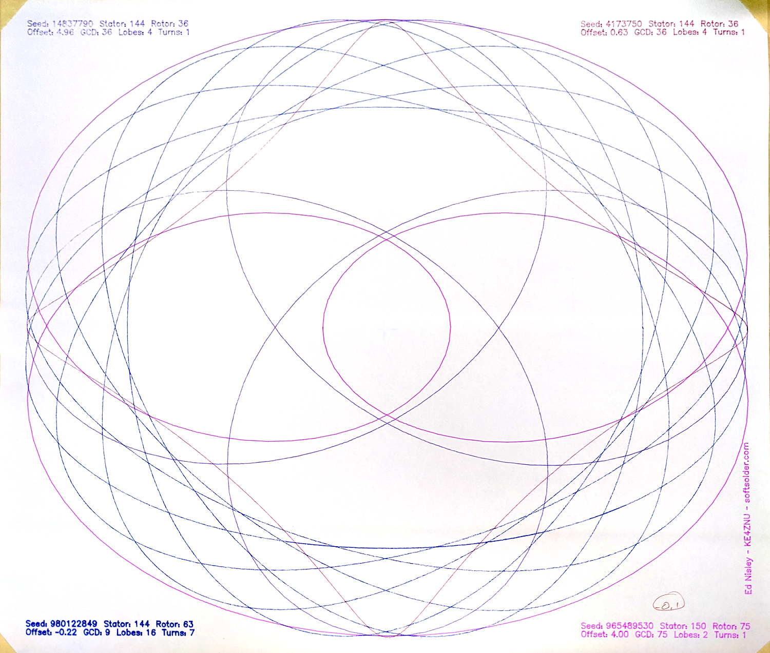
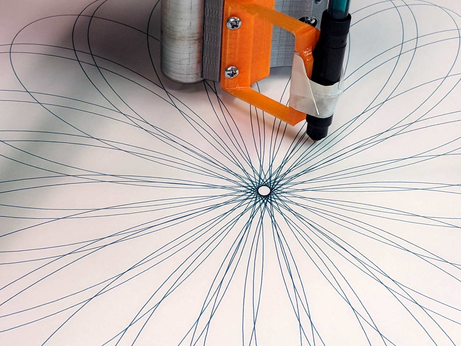
The GCMC Spirograph Generator program chooses parameters using pseudo-random numbers based on a seed fed in from the Bash script, so I was surprised to see two plots overlap exactly:
Overlaid pattern – G-Code simulator
The two overlapping traces are the 15 inward-pointing wedges around the central rosette.
The Offset isn’t quite the same, but the pen width covers up the difference.
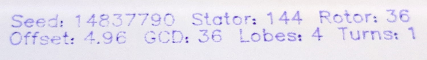
With only four Stators and 17 Rotors, the probability of picking the same pair works out to 0.25 × 0.059 = 1.4%. You can sometimes get the same number of Lobes and Turns from several different Stator + Rotor combinations, but these were exact matchs with the same indices.
The Pen Offset within the Rotor comes from a fraction computed with ten bit resolution, so each Offset value represents slightly under 0.1% of the choices. If any four adjacent values look about the same, then it’s only eight bits of resolution and each represents 0.4%.
The Rotor and Stator set the Diameter ratio, but the sign comes from what’s basically a coin flip based on the sign of a fraction drawn from 256 possibilities; call it 50%.
Overall, you’re looking at a probability of 28 ppm = 0.0028%, so I (uh, probably) won’t see another overlay for a while …
I don’t know how to factor the PRNG sequence into those numbers, although it surely affects the probability. In this case, two different seeds produced nearly the same sequence of output values, within the resolution of my hack-job calculations.
Whatever. It’s good enough for my simple purposes!