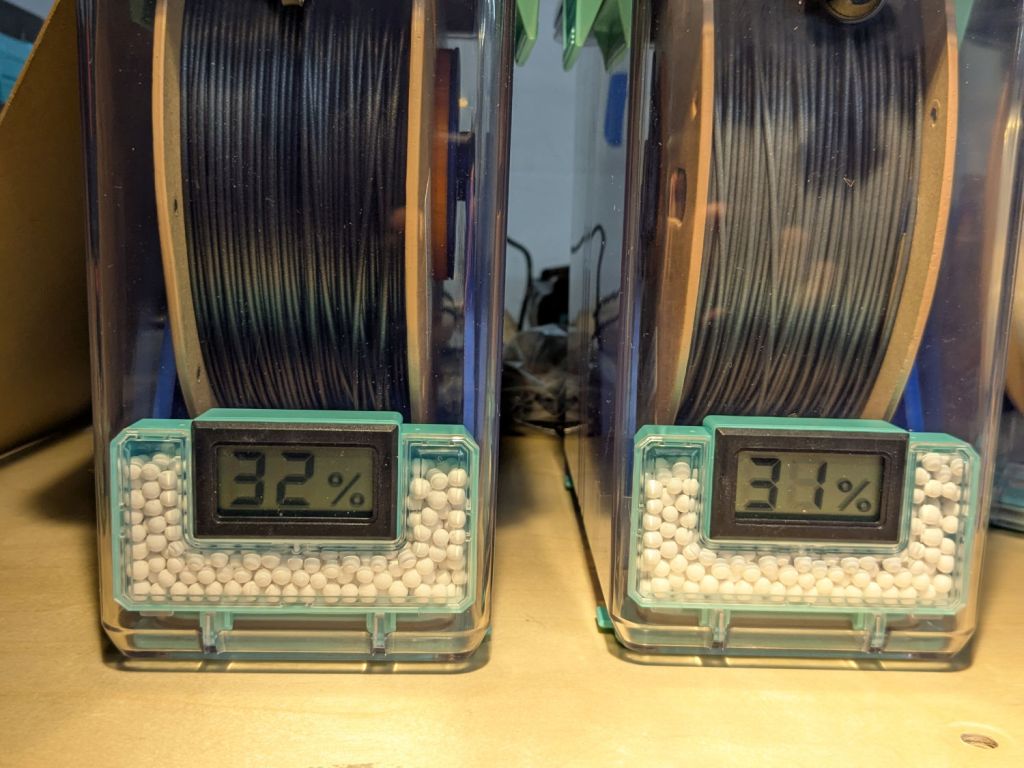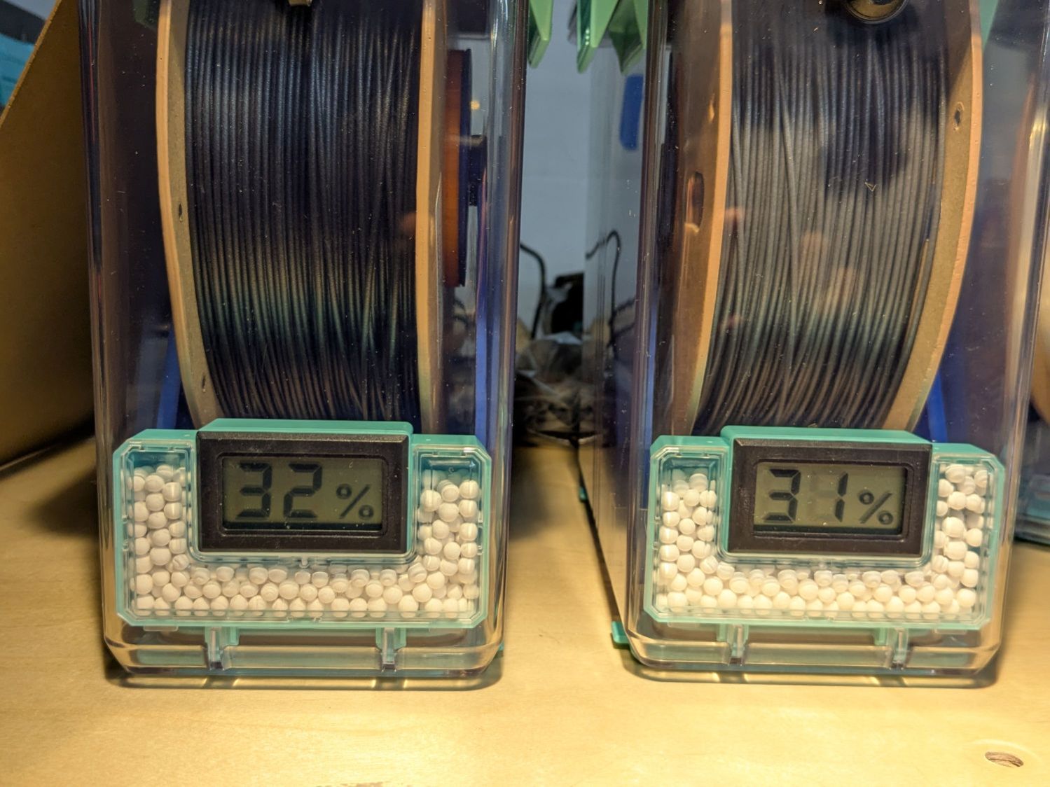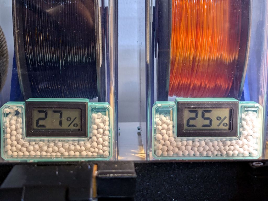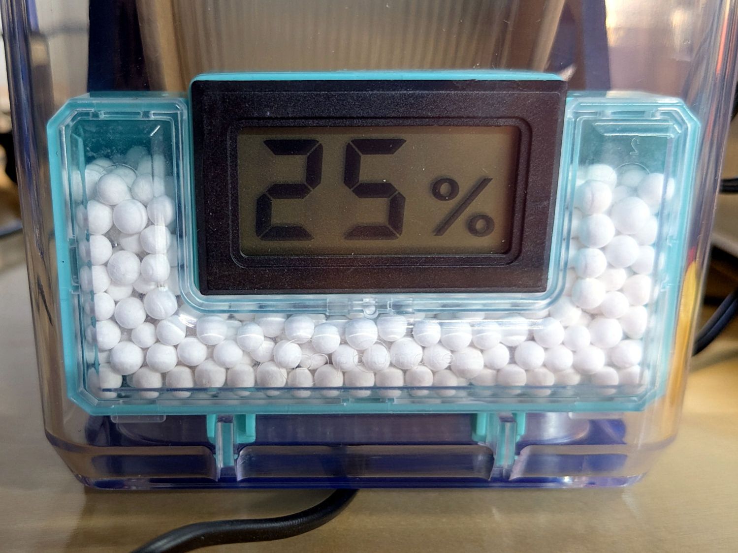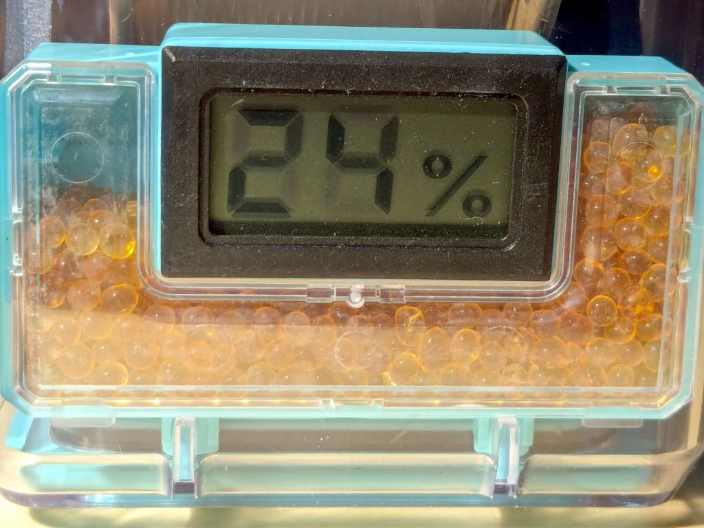
With more instrumentation in the PolyDryer TPU box and a day to let the humidity stabilize, the OEM meter reads 24 %RH, as it has all along:

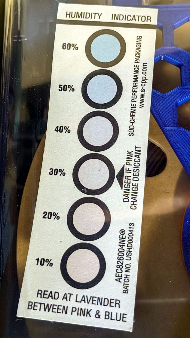
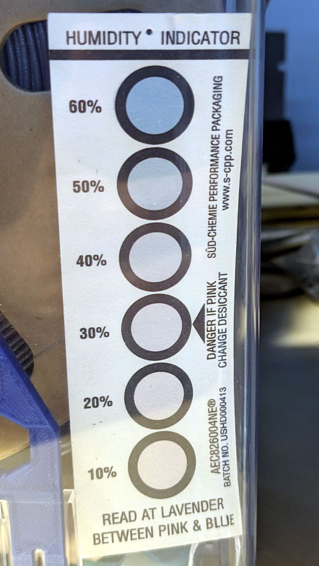
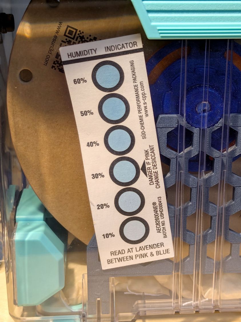
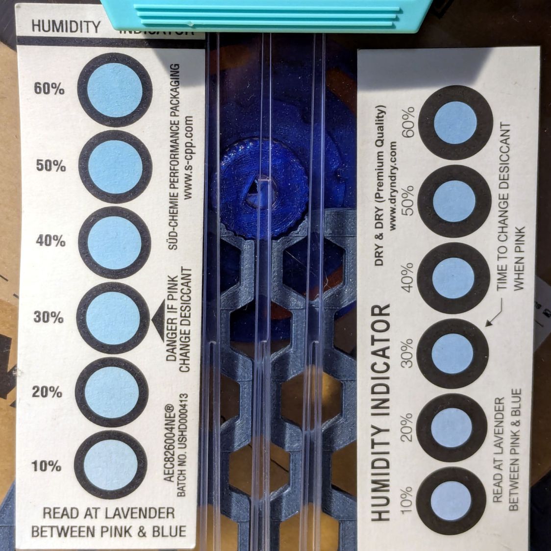
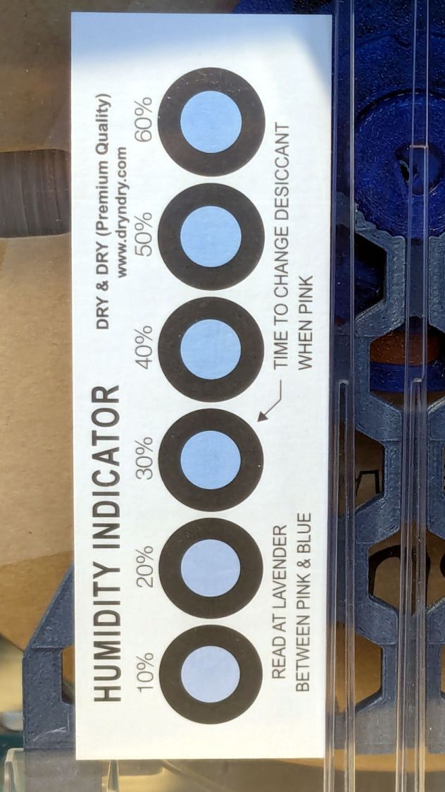
The indicator cards show the humidity is maybe a little over 10 %RH:
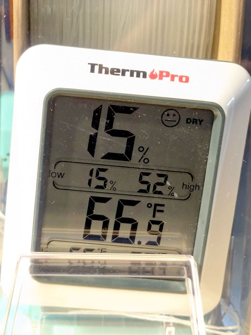
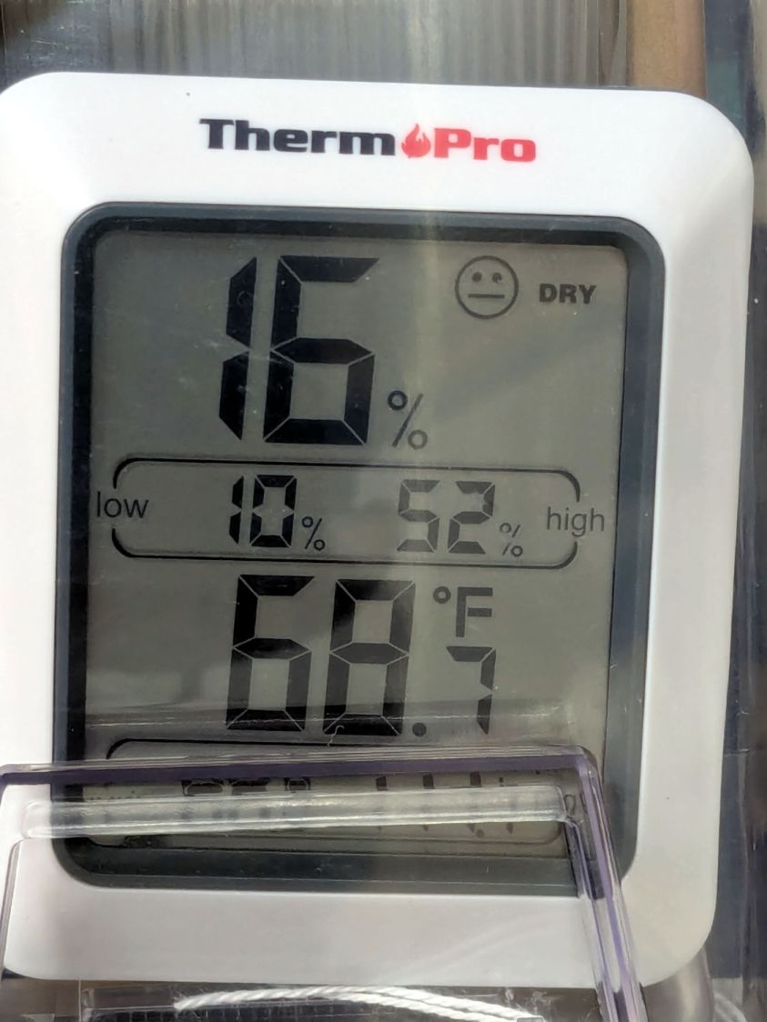
The meter jammed in the other end of the box splits the difference at 15 %RH:
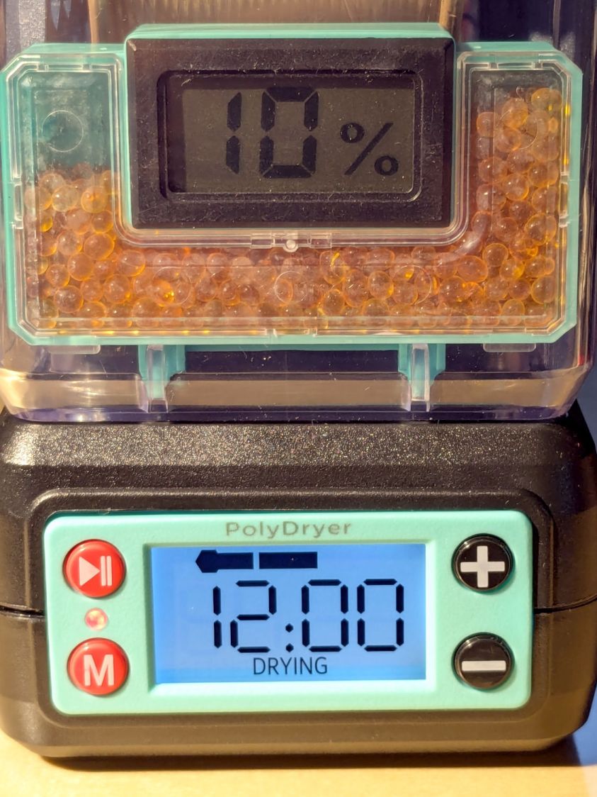
Put the box atop the improved PolyDryer, set it for the recommended 12 hours with “two bars” of oomph (which may roughly correspond to the temperature), and fire it up.
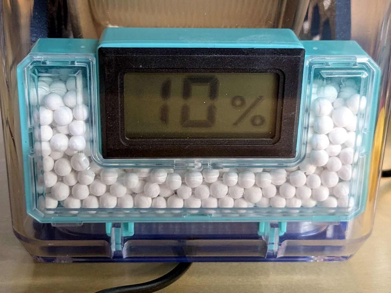
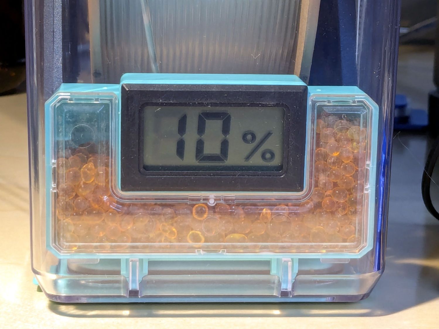
The OEM meter occasionally glitches to 10 %RH:
That type of humidity meter apparently reports values from 10 %RH upward, so this seems like the kind of glitch where the reading jams at one end of the range due to the sensor opening up / shorting / misbehaving. It does not correlate with any nearby electrical activity due to fans / heaters / 3D printers / whatever.
A little under eight hours later, it shows 17 %RH:
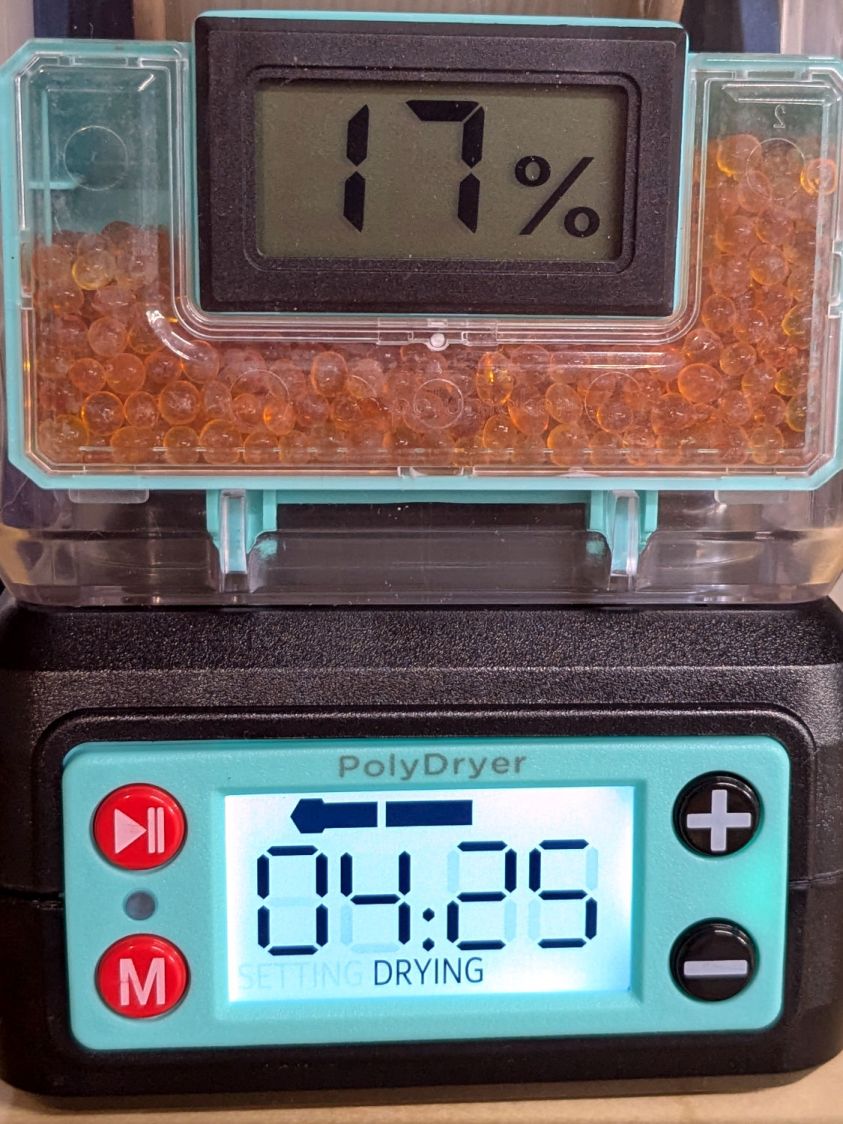
Although it still has glitches to 10 %RH.
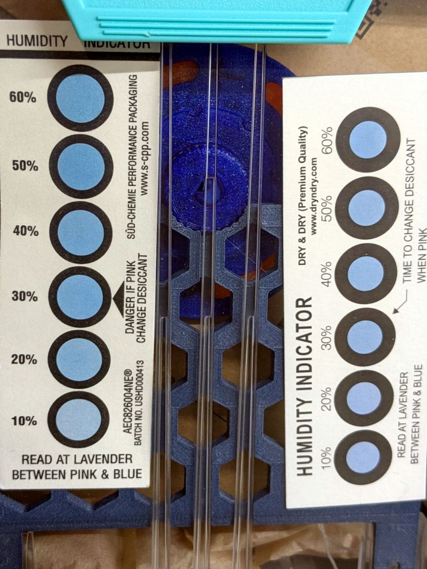
The cards look about the same, although I could be persuaded the 10% spots look ever so slightly more blue:
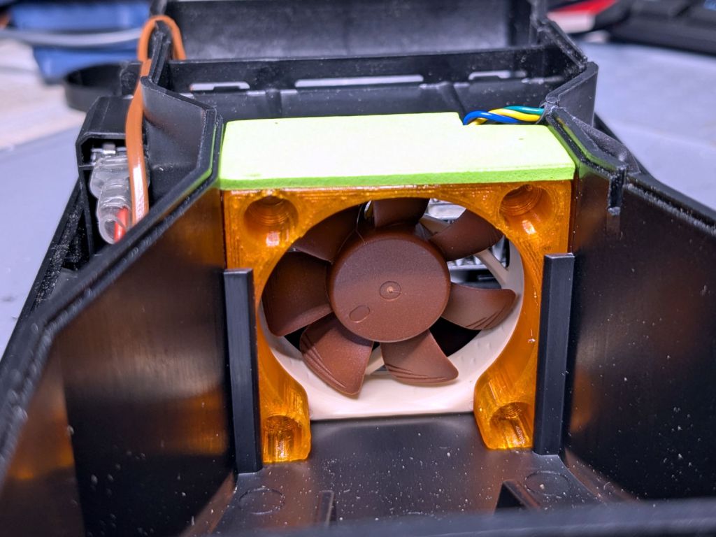
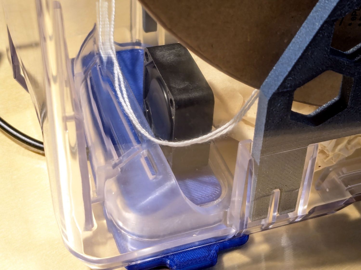
The meter in the back shows it’s toasty in there:
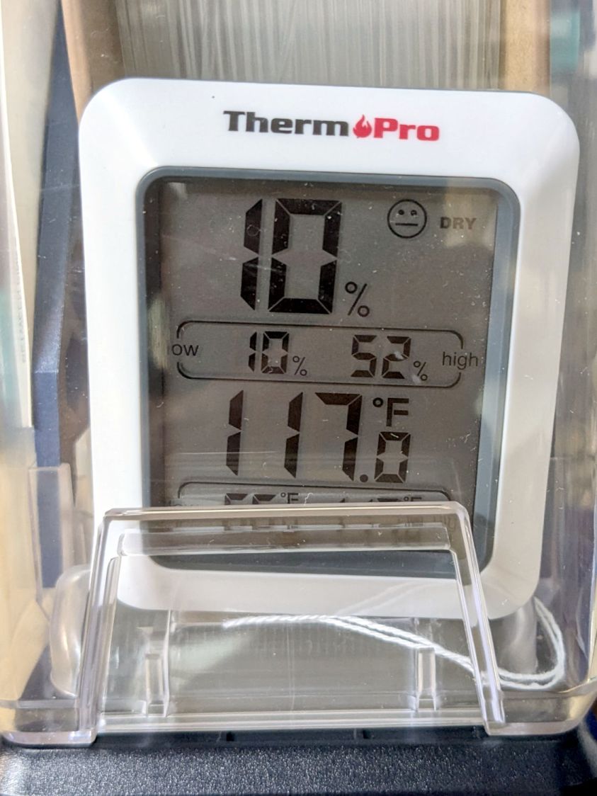
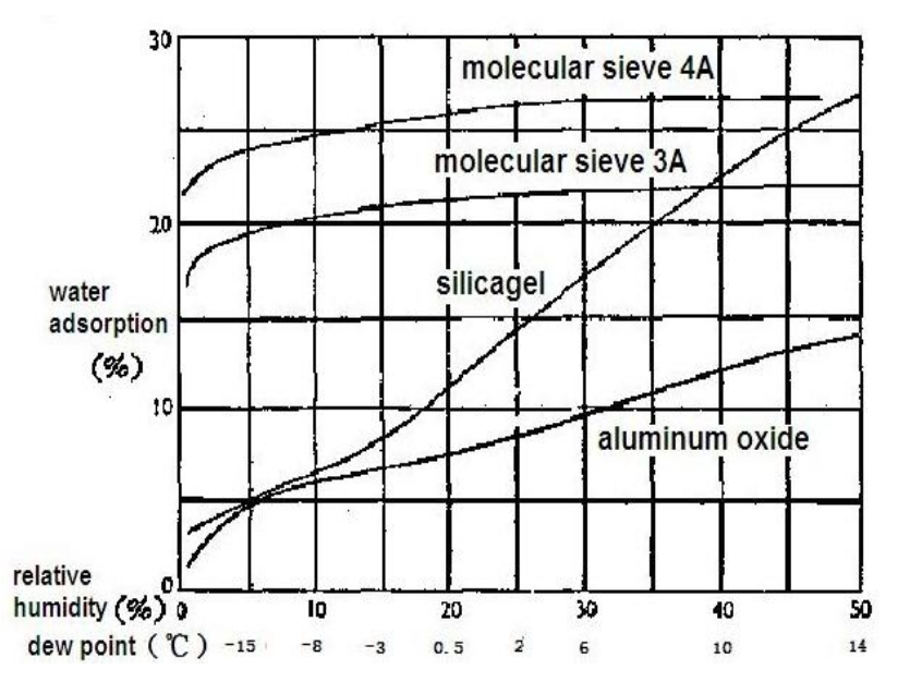
A psychrometric chart shows heating air from 66 °F & 15 %RH to 117 °F will put it at 3 %RH without removing any water vapor. This is far below the level my cheap “instrumentation” can measure, but it does suggest the meters should bottom out, regardless of whatever the silica gel is doing.
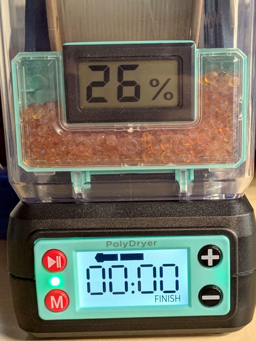
Allowing six hours to cool down & stabilize after the PolyDryer turns off in the middle of the night (because for science does not include all-nighters) shows a rebound to 26 %RH on the OEM meter:
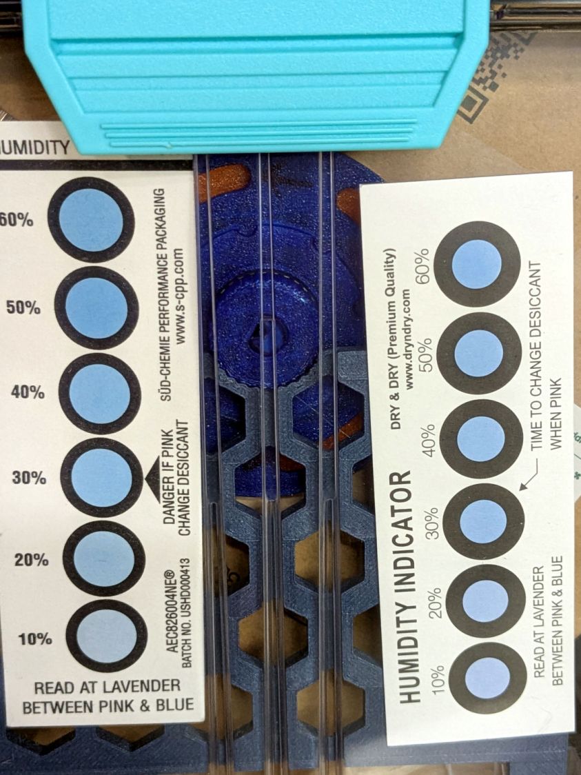
The cards remain unchanged:
The meter in the back again splits the difference at 16 %RH:
I pulled the larger meter and both cards out of the box.
After sitting undisturbed for a day, the OEM meter in the box stabilized at 10 %RH:
The card agrees, to the best of its limited resolution:
The silica gel weighs 25.0 g, exactly what it did when I loaded the meter case. I think the scale’s 0.1 g resolution exceeds its accuracy, but even if the silica gel weighed 25.2 g ≅ 0.8 % water the humidity would be under 5 %RH.
As far as I can tell:
- The filament on the spool isn’t outgassing water vapor
- The air in the TPU box remains under 15-ish %RH at normal basement temperature
- Running a PolyDryer cycle at 15-ish %RH doesn’t stuff any more water vapor in the silica gel
- Cheap humidity meters lack accuracy around 15-ish %RH
- Humidity meters take longer than you think to stabilize
- Humidity indicating cards may be as good as you (well, I) need