
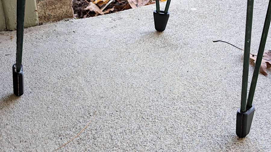
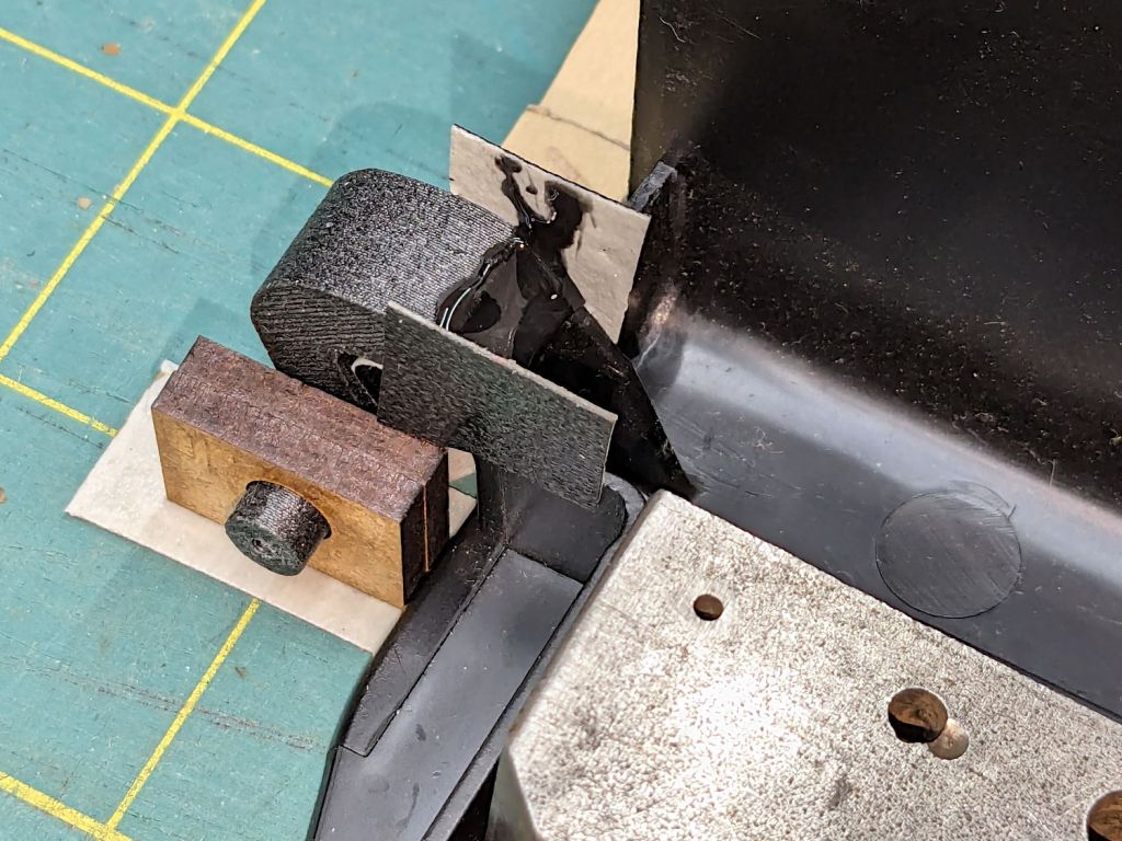
A pair of plant stands from a friend’s collection ended up in Mary’s care and cried out for feet to keep their welded steel wire legs from scratching the floor:

Admittedly, it’s not the prettiest stand you can imagine, but the sentimental value outweighs all other considerations.
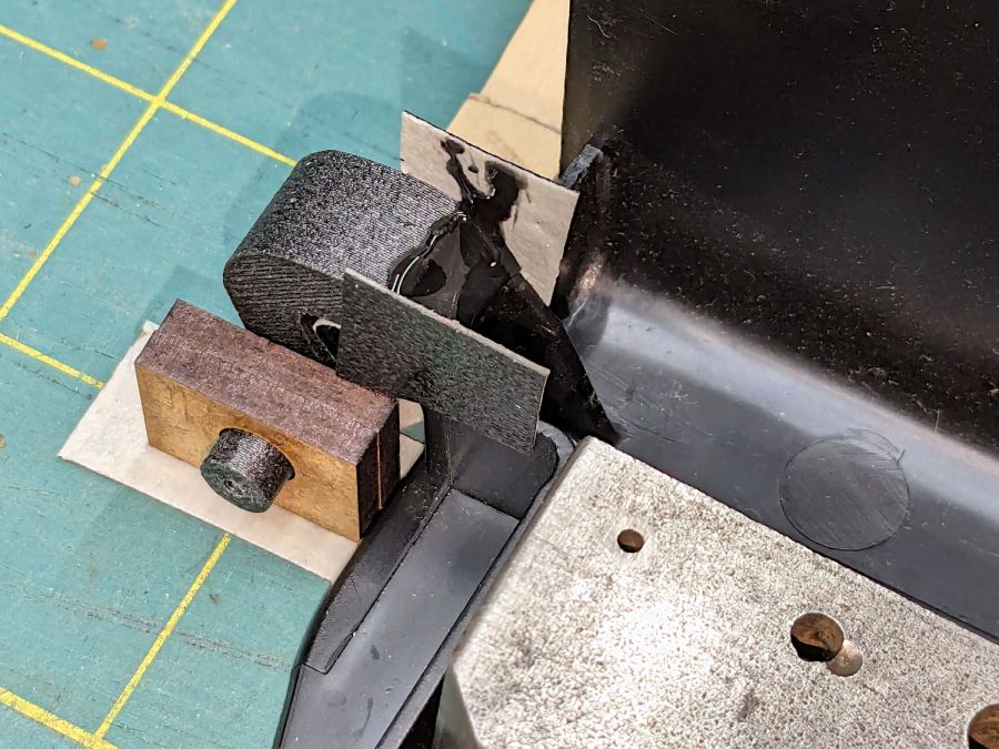
The feet are shrink-wrapped around the legs with enough curviness to look good:

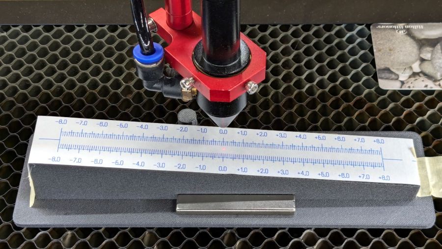
With a drain hole in the bottom to prevent water from rusting the wires any more than they already are:
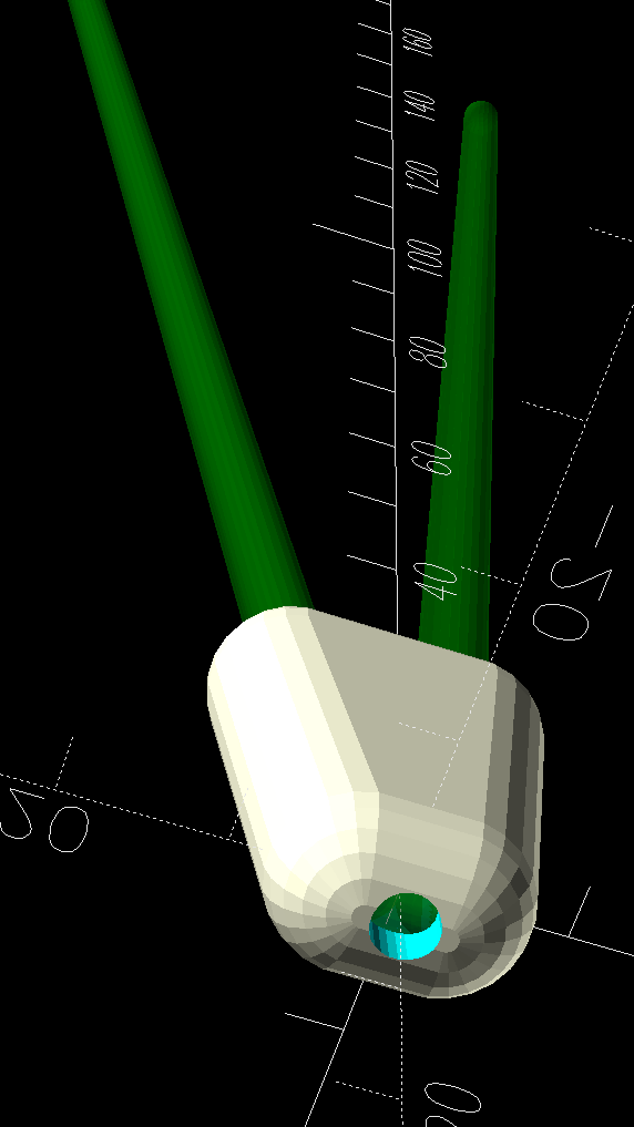
I briefly considered a flat bottom at the proper angle to sit on the floor, but came to my senses; it would never sit at the proper angle.
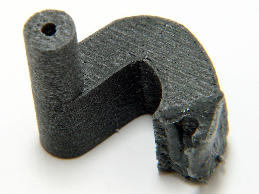
The end results snapped into place:

Of course the other stand, at first glance identical to the one above, has a different wire size and slightly different geometry, which I only discovered after printing another trio of feet. Changing the appropriate constants in the OpenSCAD program and waiting an hour produced a better outcome:
Living in the future is good, all things considered.
The OpenSCAD code as a GitHub Gist:
| // Wire plant stand feet | |
| // Ed Nisley KE4ZNU | |
| // 2024-11-06 | |
| Layout = "Show"; // [Show,Build,Leg,LegPair,FootShell,Foot,Section] | |
| /* [Hidden] */ | |
| ID = 0; | |
| OD = 1; | |
| LENGTH = 2; | |
| TOP = 0; | |
| BOT = 1; | |
| FootLength = 30.0; // vertical foot length | |
| LegRings = // [255.0,350.0,300.0]; // top dia, bottom dia, vertical height | |
| [260.0,312.0,300.0]; | |
| WireOD = //4.6 + 0.4; // oversize to handle bent legs | |
| 5.7 + 1.0; | |
| DrainOD = 4.0; // drain hole in the bottom | |
| LegWidth = // [65.0,9.7]; // outer width at top & bottom | |
| [95.0, 12.0]; | |
| LegAngle = atan((LegWidth[TOP] – LegWidth[BOT])/(2*LegRings[LENGTH])); | |
| StandAngle = atan((LegRings[TOP] – LegRings[BOT])/(2*LegRings[LENGTH])); | |
| WallThick = 3.0; | |
| FootWidth = 2*[WallThick,WallThick] + | |
| [LegWidth[BOT] + LegWidth[TOP]*FootLength/LegRings[LENGTH],LegWidth[BOT]]; | |
| echo(FootWidth=FootWidth); | |
| NumSides = 2*3*4; | |
| Protrusion = 0.1; | |
| //—– Set up pieces | |
| module Leg() { | |
| hull() | |
| for (k = [0,1]) | |
| translate([0,0,k*LegRings[LENGTH]]) | |
| sphere(d=WireOD,$fn=NumSides); | |
| } | |
| module LegPair() { | |
| for (i = [-1,1]) | |
| translate([i*(LegWidth[BOT] – WireOD)/2,0,0]) | |
| rotate([0,i*LegAngle,0]) | |
| rotate(180/NumSides) | |
| Leg(); | |
| hull() // simulate weld for flat bottom | |
| for (i = [-1,1]) | |
| translate([i*(LegWidth[BOT] – WireOD)/2,0,0]) | |
| rotate([0,i*LegAngle,0]) | |
| rotate(180/NumSides) | |
| sphere(d=WireOD,$fn=NumSides); | |
| } | |
| module FootShell() { | |
| difference() { | |
| hull() { | |
| for (i = [-1,1]) { | |
| translate([i*((FootWidth[BOT] – WireOD)/2 – WallThick),0,0]) | |
| rotate(180/NumSides) | |
| sphere(d=(WireOD + 2*WallThick),$fn=NumSides); | |
| translate([i*((FootWidth[TOP] – WireOD)/2 – WallThick),0,FootLength – WireOD/2]) | |
| rotate(180/NumSides) | |
| sphere(d=(WireOD + 2*WallThick),$fn=NumSides); | |
| } | |
| } | |
| translate([0,0,FootLength + FootLength/2]) | |
| cube([2*FootWidth[TOP],10*WallThick,FootLength],center=true); | |
| rotate(180/NumSides) | |
| cylinder(d=DrainOD,h=4*FootLength,center=true,$fn=NumSides); | |
| } | |
| } | |
| module Foot() { | |
| difference() { | |
| FootShell(); | |
| hull() | |
| LegPair(); | |
| } | |
| } | |
| //—– Build it | |
| if (Layout == "Leg") | |
| Leg(); | |
| if (Layout == "LegPair") | |
| LegPair(); | |
| if (Layout == "FootShell") | |
| FootShell(); | |
| if (Layout == "Foot") | |
| Foot(); | |
| if (Layout == "Section") | |
| difference() { | |
| Foot(); | |
| cube([FootWidth[TOP],(WireOD + 2*WallThick),2*FootLength],center=false); | |
| } | |
| if (Layout == "Show") { | |
| rotate([StandAngle,0,0]) { | |
| Foot(); | |
| color("Green",0.5) | |
| LegPair(); | |
| } | |
| } | |
| if (Layout == "Build") | |
| translate([0,0,FootLength]) | |
| rotate([0*(90-StandAngle),180,0]) | |
| Foot(); |


