Ed Nisley's Blog: Shop notes, electronics, firmware, machinery, 3D printing, laser cuttery, and curiosities. Contents: 100% human thinking, 0% AI slop.
The rules for disposing of latex paint around here require that it be “dried with sawdust”, whatever that means. Over the years we’ve accumulated quite a lot of latex paint, in addition to a rich stockpile that Came With The House™, and I simply don’t have that much sawdust.
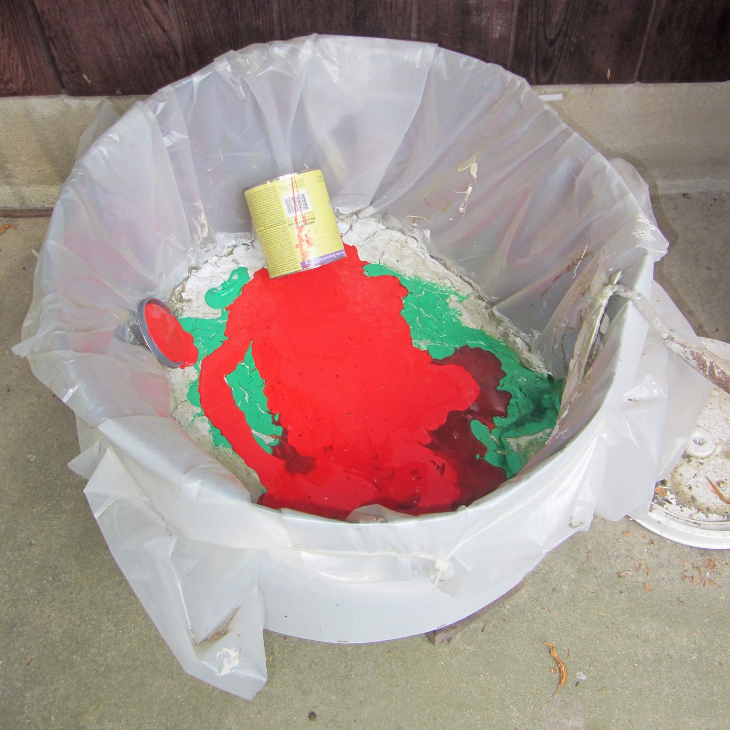
Since they don’t seem to object to dried latex paint, I made a drying tub by stapling aluminum flashing around a stand that used to hold a water heater off the basement floor, lined it with heavy plastic, and started pouring latex paint into it:
Paint drying tub
After a year of intermittently dumping paint, that solid latex cookie must be two inches thick and I suppose it’s time to toss the first batch.
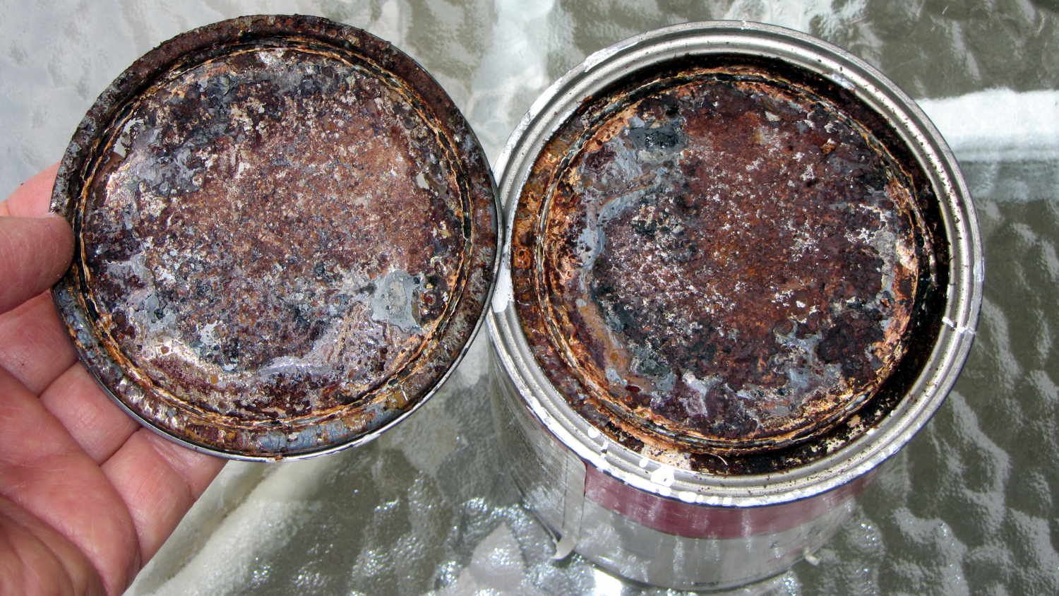
For what it’s worth, I discovered that storing paint cans upside down doesn’t guarantee that the paint remains fresh. This can had a solid latex cookie against the lid, with plenty of corrosion to go around:
Paint can stored upside-down – interior
The coagulated paint above the latex cookie was as horrible as you might expect.
I hauled the Kenmore 158 sewing machine and controller to a Squidwrench meeting for some current measurements (and, admittedly, showing it off) while schmoozing. After hauling it home and setting it up on my bench again, it didn’t work: the motor didn’t run at all.
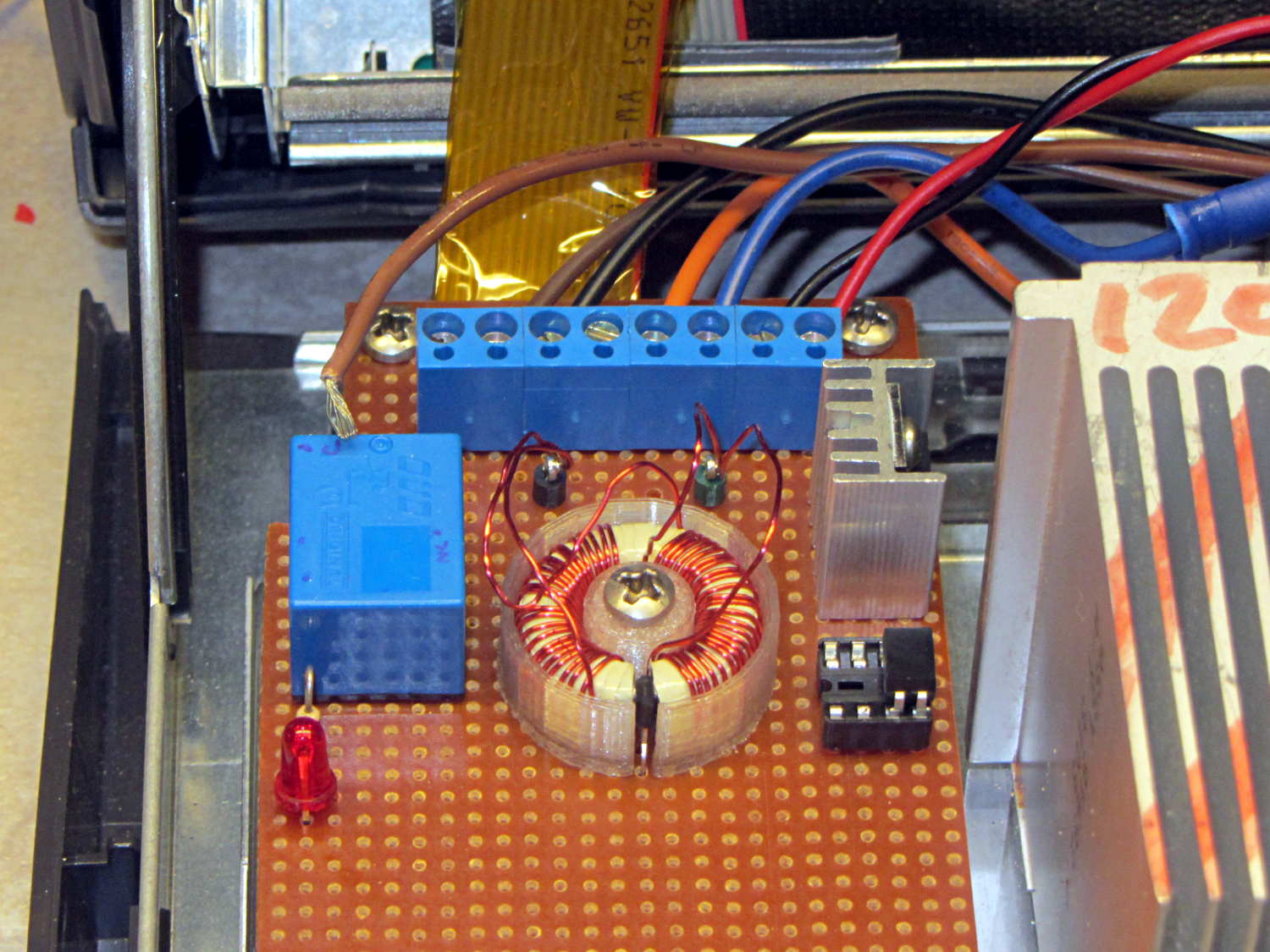
While doing the usual poking around under the cover, I spotted this horrifying sight:
Loose AC line hot wire
The brown insulation tells you that’s a hot wire from the AC line and, in fact, it’s coming directly from the line fuse; it’s live whenever the plug is in.
It’s a stranded wire to allow flexing without breaking, but that same flexibility allows it to squeeze its way out of a tightly fastened screw terminal. In principle, one should crimp a pin on the wire, but the only pins in my heap don’t quite fit along the screw terminal block.
This sort of thing is why I’m being rather relentless about building a grounded, steel-lined box with all the pieces firmly mounted on plastic sheets and all the loose ends tucked in. If that wire had gone much further to the side or top, it would have blown the fuse when it tapped the steel frame. The non-isolated components on that board are facing you, with those connections as far from the terminal block as they can be.
Engineers tend to be difficult to live with, because we have certain fixed ways of doing things that are not amenable to debate. There’s probably a genetic trait involved, but we also realize that being sloppy can kill you rather quickly; the universe is not all about pink unicorns and rainbows.
In fact, the universe wants you dead.
Now, go play with those goblins and zombies tonight…
Memo to Self: Tighten those terminals every now and again. A wire will come loose shortly after you forget to do that, of course.
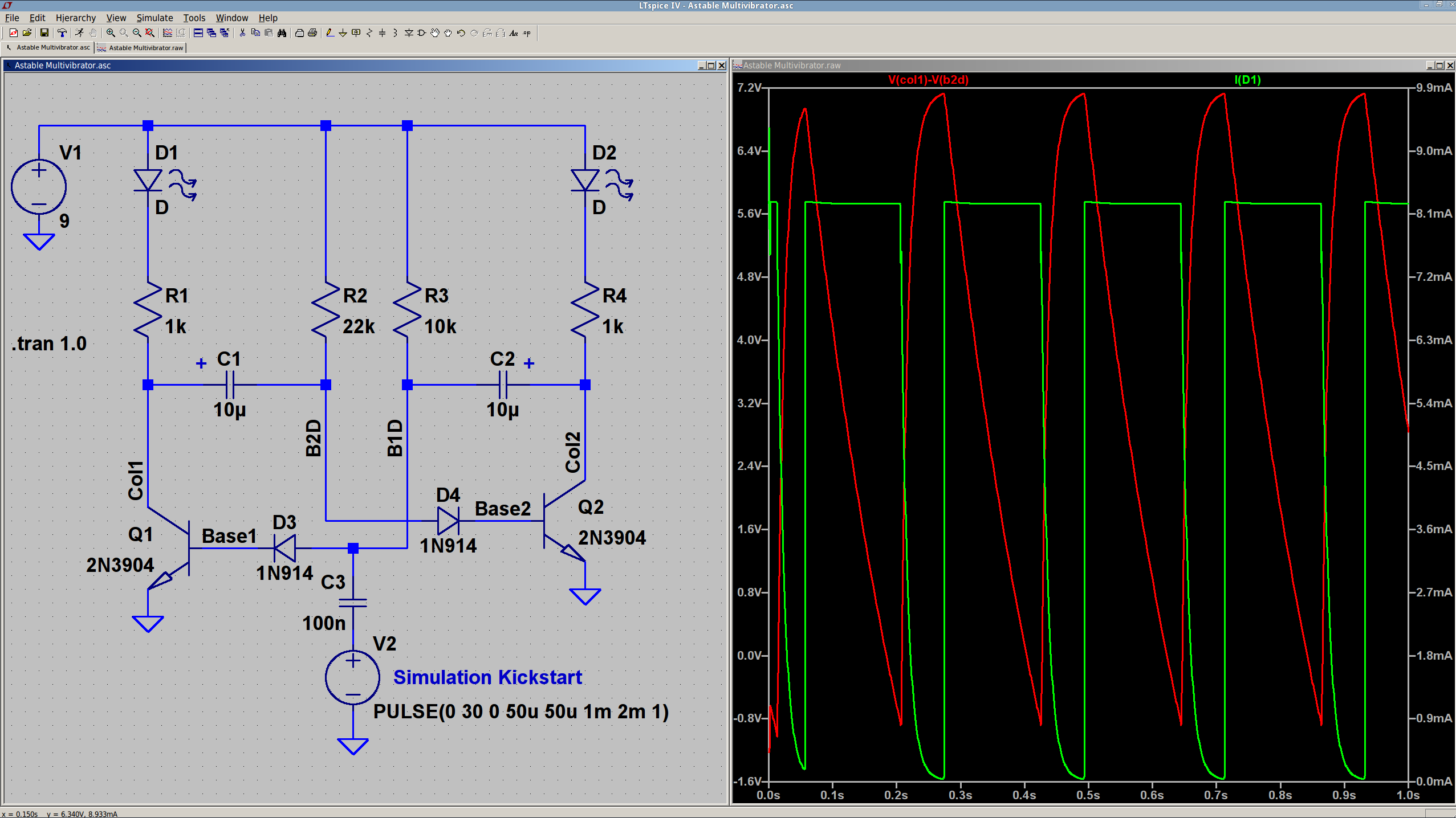
The 10 µF caps scale the output to visible blinkiness. Their polarity may seem backwards, but the red trace in the simulation shows that the net voltage is positive in that direction for nearly the entire cycle. They see only two forward biased junctions in the other direction, so they shouldn’t blow up.
I built it with resistors from the SqWr junk box parts cabinet that were close to the nominal values.
Connecting the transistor base / cap charging resistors to the power supply, rather than the LEDs, gets rid of the tiny current when the LEDs should be off.
The cap-and-pulse-generator dingus on the bottom kickstarts the simulation; it doesn’t have any physical significance.
Memo to Self: Build one with a pair of ET227 transistors and some 100 W tungsten bulbs…
Dell built the GX270 I’m repurposing back in 2004, early on in the capacitor plague years, but only one of the system board caps showed signs of leakage:
Capacitor plague – 2004 Dell Edition
While I was harvesting some of the connectors, it occurred to me that those powdered iron inductors might make good current sensors, as they’re already wound with heavy gauge copper wires.
I picked an inductor with enough turns and, although slitting didn’t pose much of a problem, the saw did make a mess of the turns adjacent to the cut:
Powdered iron toroid – slitting
Iron powder has more magnetic remnance than ferrite, to the extent that iron swarf clogged the gap. After the first pass, I ran the slit toroid through the degausser to shake it clean and see what damage had been done. It looked OK, so I realigned it on the saw blade and continued the mission, with all the dust vanishing into the vacuum cleaner’s snout.
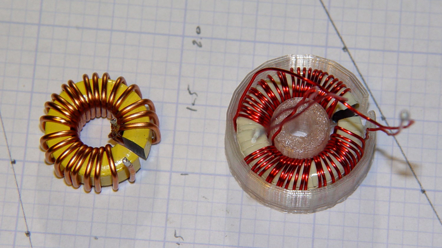
Removing the damaged sections left 22 turns. For comparison, I converted the 56 turn ferrite toroid into a 25 turn model by paralleling two 25 turn sections:
Slit toroids – iron – ferrite
The enamel wire on the iron toroid measures 40 mil diameter, close enough to 18 AWG.
Paralleling two 24 AWG windings on the ferrite toroid produces twice the copper area of a single winding, so the resistance is the same as a single 21 AWG winding (3 AWG steps = factor of two area change). That’s three steps smaller than the 18 AWG on the iron toroid, so the resistance is a factor of two larger than the heavier wire.
The paralleled winding has the advantage of reducing the power dissipation required to produce the same magnetic flux density, without the difficulty of winding heavier wire. That may not actually matter, given the relatively low currents required by the motor in normal operation.
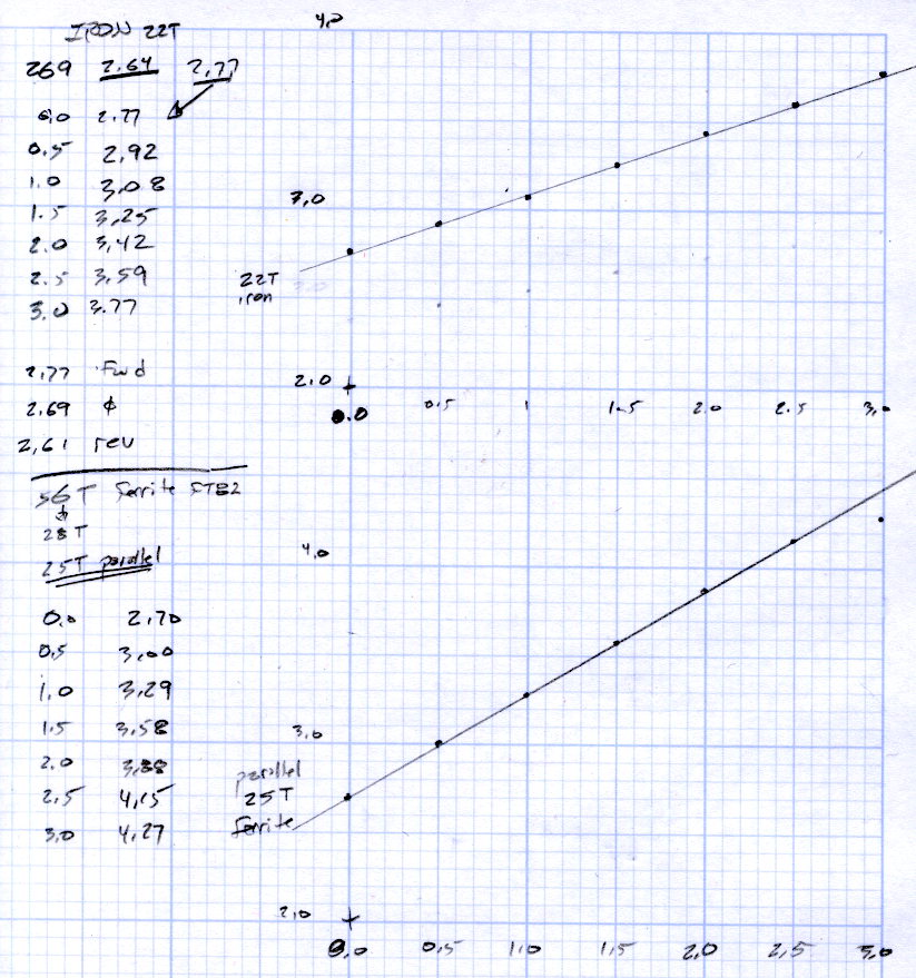
Wedging a Hall sensor into the gaps and stepping the current produced two useful graphs:
Iron and ferrite toroids – Hall sensor output
The iron toroid has lower permittivity (less flux density for a given magnetizing force), which means the full-scale range exceeds 3 A and the useful range up to 1 A covers only 300 mV.
The last point on the ferrite curve shows the Hall sensor output saturating just over 4 V, with 1.5 V of range.
The slope, in mV/A
Powdered iron: 340
Ferrite: 540
Boosting the slope of the powdered iron by 25/22 gives 386 mV/A, so the iron permeability really is 70% of the ferrite. That’s modulo the gap size, of course, which surely differs by enough to throw out all the significant digits.
Obviously, an op amp circuit to remove the offset and rescale the output to 0-5 V will be in order.
The previous graph for the ferrite toroid with the complete 56 turn winding shows, as expected, about twice the output of this 25 turn version:
FT82-43 – 56 turns – 24 AWG
The linear part of that line is 1375 mV/A, although I can’t vouch that the data came from the same Hall effect sensor. Scaling it by 25/56 gives 613 mV/A, suggesting it’s not the same sensor.
Having developed an emotional attachment to the ferrite toroid, I’ll use it in the first pass of the current feedback circuit. If the motor need a bit less sensitivity or lower resistance, the powdered iron toroid looks like a winner.
Memo to self: Always degauss iron toroids before slitting!
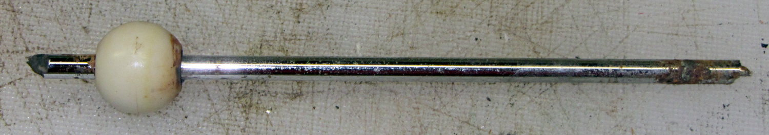
Once again, the black bathroom sink drain stopper stopped popping up. Having had this happen once before, I knew what I would find:
Corroded bathroom sink drain lever
The lever arm to the left of the ball should be about twice that long, minus the jagged end.
I slid the ball rightward to expose more rod, introduced both ends to Mr. Bench Grinder to round them off, scuffed up the short end with sandpaper to improve its griptivity, then slobbered on enough JB KwikWeld to cover the entire length of rod that will live inside the drain:
Epoxy-coated bathroom sink drain lever
The first failure took 9 years, this one took 4…
Memo to Self: Next time, replace the rod with something that doesn’t corrode.
Mulling over how to add a 1/rev sensor to the sewing machine motor, it occurred to me that simply drilling a hole through the pulley would provide a clean optical path and a convenient 2/rev output signal.
However, the OEM pulley doesn’t extend beyond the end of the shaft:
Kenmore 158 – AC drive motor – overview
Rather than drill a hole in the shaft or (attempt to) affix something onto a pulley that spins at 10 kRPM, I figured I should make another pulley and mutilate that.
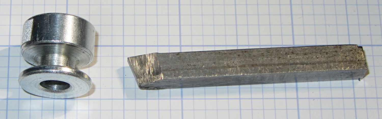
Because this will surely call for more than one new pulley before I get everything right, a lathe form tool seemed in order. Introducing a suitable blank from the Bin o’ 1/4 Inch Bits to Mr. Bench Grinder produced a likely looking candidate, with an included angle of about 35° (a skosh over 17° on each side) and sized just a wee bit narrower than the pulley groove.
From the top:
Pulley form tool – top
From the side:
Pulley form tool – side
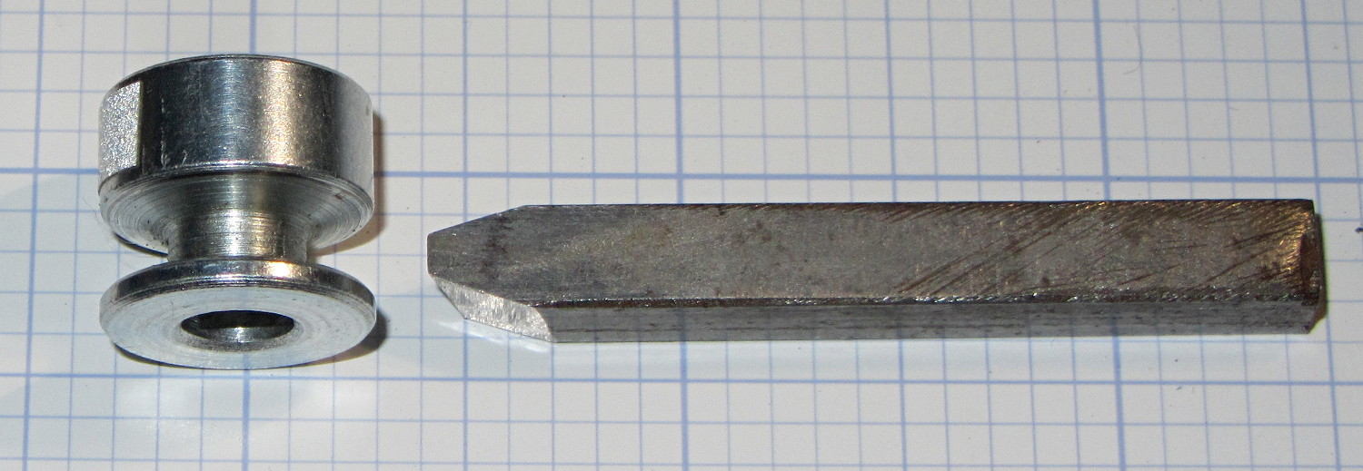
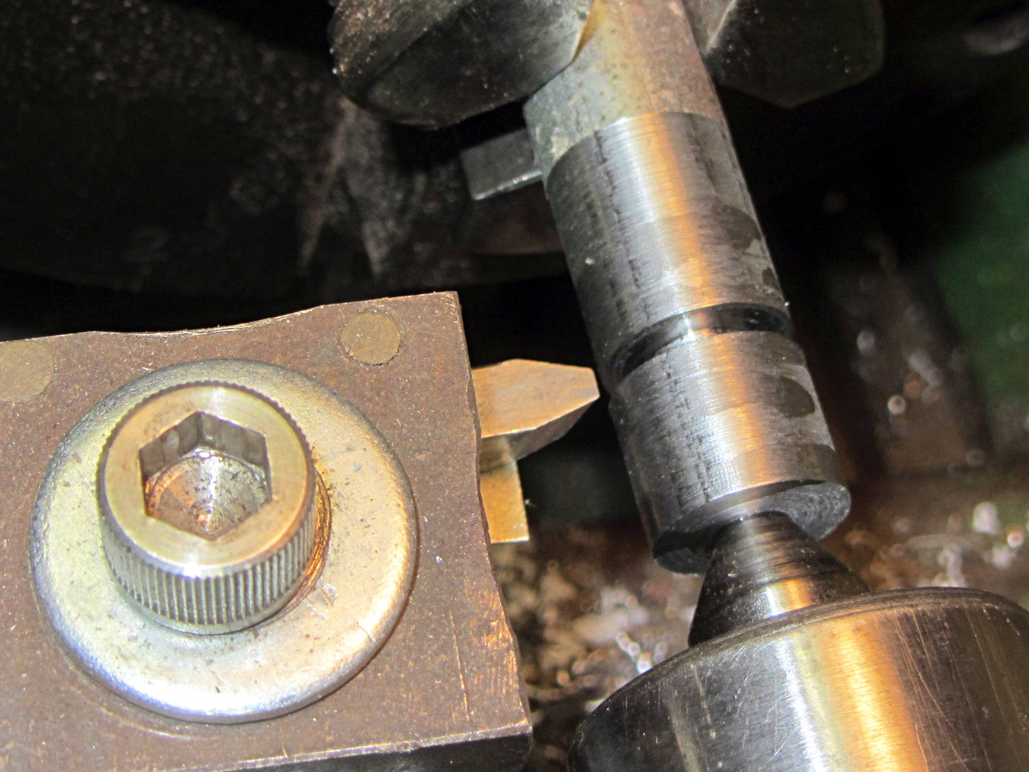
Skim the surface of a 5/8 inch rod to match the pulley OD, plunge a cutoff tool to make most of the cut, insert bit in holder, align perpendicular to workpiece, line up to center of cut, slobber on more cutting lube:
Pulley form tool – prepared blank
Plunging the tool slowly into the cut produces … no chips … nothing … smoke?
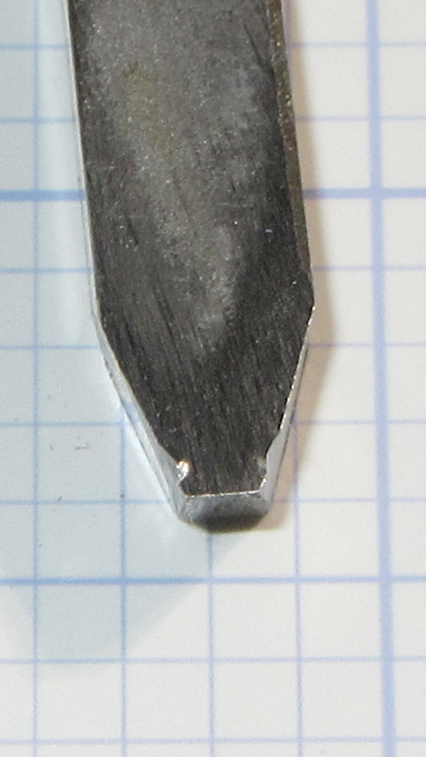
Come to find out that the Bin o’ 1/4 Inch Bits contained not just lathe tool bits & blanks made from tool steel, but one length of 1/4 inch square key stock made from ordinary soft steel:
Pulley form tool – damage
I should have known that from the type of sparks flying off the grinding wheel, right?
You knew that just from looking at the first picture, because a real lathe bit blank wouldn’t be all beat to shit…
The 170° fisheye lens on the HDR-AS30V action camera protrudes from the front of the case, the better to view the passing scenery:
Sony HDR-AS30V Action Camera
Unfortunately, that means there’s nothing to protect it when the scenery gets a bit too close.
Mounting it upside-down in the skeleton frame provides a bit of protection, by putting it inside the straight line connecting the helmet brim with the top of the frame:
Sony HDR-AS30V camera on bike helmet – inverted
That won’t protect it from severe impacts, but perhaps a casual drop won’t scar the lens. You can tell from the scuffs that the helmet does get dropped every now and then.
When you remove the skeleton mount from the helmet, grip the camera between finger and thumb while releasing the latch with your other hand. The mount will dangle from your fingers and the camera won’t slide out; if you don’t have both hands free, don’t mess with the camera.
Even though it doesn’t look at all like a GoPro Hero, everybody recognizes the “camera on helmet” meme and, in general, behaves a bit more circumspectly. I didn’t see that coming, not at all.