The Smell of Molten Projects in the Morning

Ed Nisley's Blog: Shop notes, electronics, firmware, machinery, 3D printing, laser cuttery, and curiosities. Contents: 100% human thinking, 0% AI slop.

Tag: Memo to Self

Maybe next time I’ll get it right

  • Vacuum Tube LEDs: Ersatz Heat Sink Plate Cap

    I wanted a slightly larger “plate cap” to fit a big incandescent bulb and it seemed a fake heatsink might add gravitas to the proceedings:

    Vacuum Tube LEDs - large incandescent bulb
    Vacuum Tube LEDs – large incandescent bulb

    Yeah, that antique ceramic socket holds the bulb at a rakish angle. Worse, even though I painstakingly laid out the position of the heatsink atop the bulb, it’s visibly off-center. Which wouldn’t be so bad, had I not epoxied the damn thing in place.

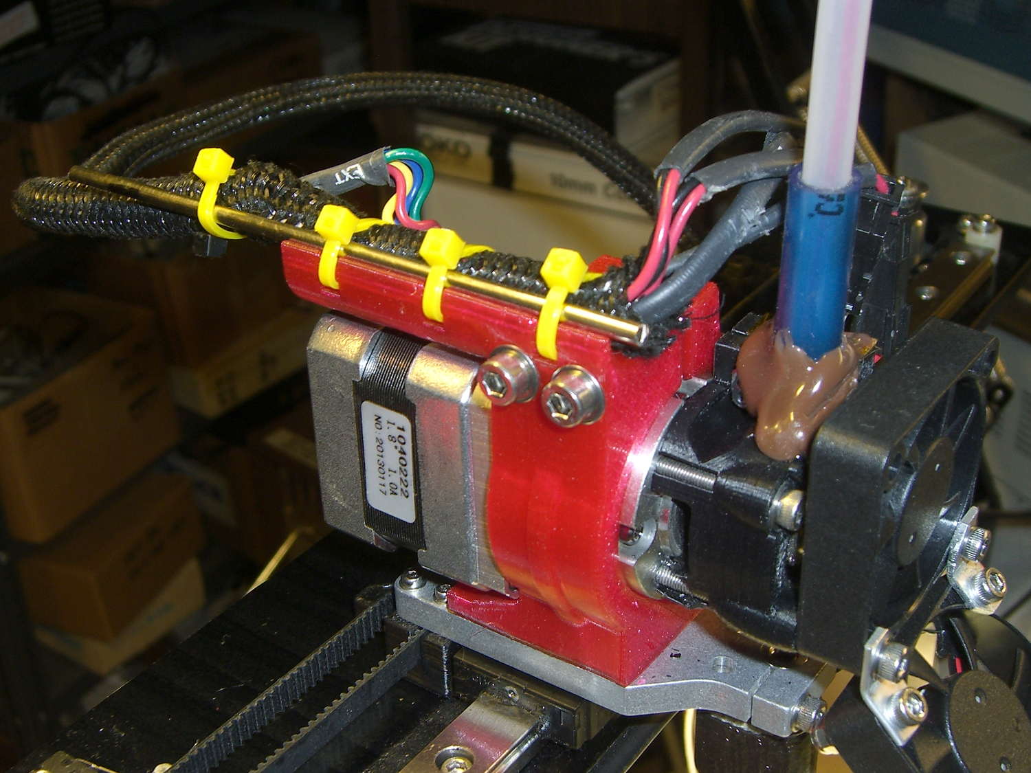
    After reaming out the M2’s filament drive, the entire blue base printed without incident.

    A closer look at the cap:

    Vacuum Tube LEDs - ersatz heatsink plate cap
    Vacuum Tube LEDs – ersatz heatsink plate cap

    Memo to Self: Next time, line it up with the vertical glass support inside the bulb and ignore the external evidence.

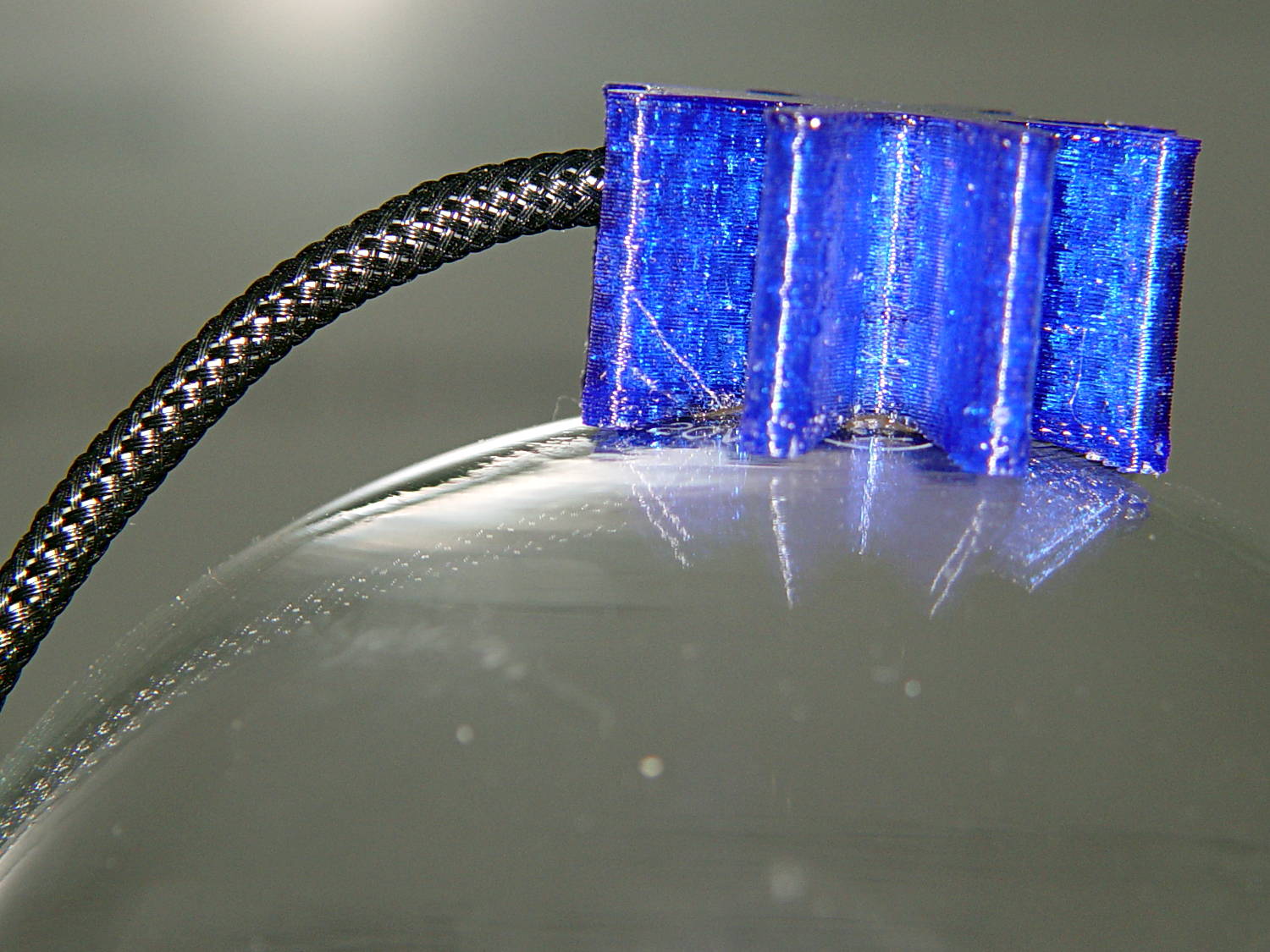
    The boss has a hole for the braid-enclosed cable to the knockoff Neopixel:

    Vacuum Tube Lights - finned cap - Slic3r preview
    Vacuum Tube Lights – finned cap – Slic3r preview

    The cupped surface perfectly fits the bulb’s 3.75 inch diameter. While you wouldn’t mill out a real heatsink, it definitely looks better this way and (alas) gives the epoxy more footprint for a better grip.

    I built the fins with a 1/8 inch cutter in mind, so the fin root radius allows for a G3/G3 arc without gouging. I doubt machining a fake heatsink from aluminum makes any sense, but the cheap extruded heatsinks on eBay don’t look very good. Plus, they sport completely unnecessary tapped holes for LED mounts and suchlike.

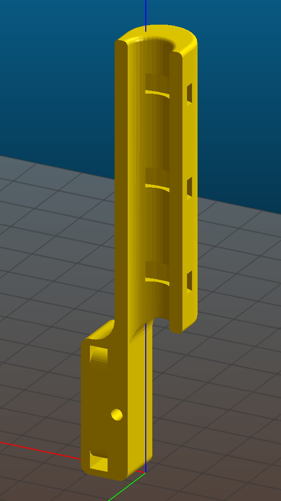
    A cross-section shows the wiring channel and cable entry:

    Vacuum Tube Lights - fin cap solid model - section
    Vacuum Tube Lights – fin cap solid model – section

    I epoxied the Neopixel in place, applied double-sided carpet tape to the whole thing, then painstakingly trimmed around the fins with an Xacto knife:

    Vacuum Tube LEDs - Ersatz Heatsink plate cap - tape
    Vacuum Tube LEDs – Ersatz Heatsink plate cap – tape

    That looked better from the top side (where it was completely hidden) and came heartbreakingly close to working, but after about a day the cable + braid put enough torque on the cap to peel it off the bulb. Obviously, the tape holds much less enthusiastically after that.

    Part of the problem came from the cable’s rather sharp angle just outside the cap:

    Vacuum Tube LEDs - Ersatz Heatink plate cap - detail
    Vacuum Tube LEDs – Ersatz Heatink plate cap – detail

    Rakish angle, indeed. Two of ’em, in fact.

    Unlike the smaller cap on the halogen bulb, this time I didn’t bother with a brass tube ferrule, mostly to see how it looks. I think it came out OK and the black braid looks striking in person. Conversely, a touch of brass never detracts from the appearance.

    Obviously, the cable wasn’t long enough, either. Part of that problem came from underestimating the braid length: it shortens dramatically when slipped over the cable, even when you expect shortening. Somehow I managed to overlook that, despite cutting the cable quite long enough, thankyouverymuch. There’s a tradeoff between gentle angles and having the cable stick out too far for comfort.

    Memo to Self: Use a cable at least four inches longer than necessary, measure the combined cable + braid assembly after screwing the bulb in the socket, and don’t epoxy anything before all the parts are ready for assembly.

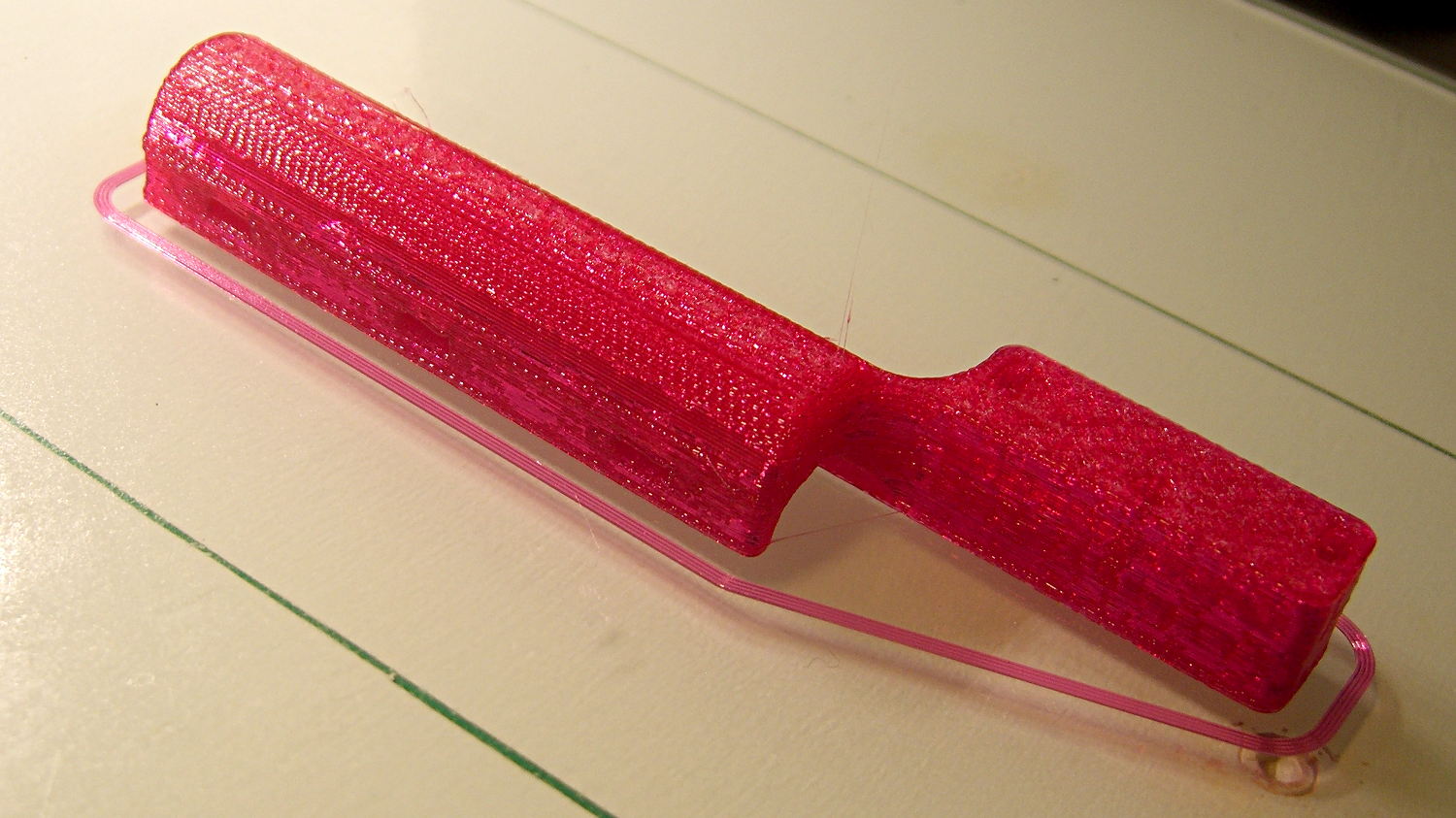
    That’s why it’s a prototype made out of blue PETG…

    Protip: running old ceramic sockets through the dishwasher greatly simplifies their subsequent cleanup.

    All in all, I like it.

    The OpenSCAD source code as a GitHub gist:

    // Vacuum Tube LED Lights
    // Ed Nisley KE4ZNU January 2016
    Layout = "FinCap"; // Cap LampBase USBPort Socket(s) (Build)FinCap
    Section = true; // cross-section the object
    Support = true;
    //- Extrusion parameters must match reality!
    ThreadThick = 0.25;
    ThreadWidth = 0.40;
    HoleWindage = 0.2;
    Protrusion = 0.1; // make holes end cleanly
    inch = 25.4;
    function IntegerMultiple(Size,Unit) = Unit * ceil(Size / Unit);
    //———————-
    // Dimensions
    // https://en.wikipedia.org/wiki/Tube_socket#Summary_of_Base_Details
    T_NAME = 0; // common name
    T_NUMPINS = 1; // total, with no allowance for keying
    T_PINBCD = 2; // tube pin circle diameter
    T_PINOD = 3; // … diameter
    T_PINLEN = 4; // … length (overestimate)
    T_HOLEOD = 5; // nominal panel hole from various sources
    T_PUNCHOD = 6; // panel hole optimized for inch-size Greenlee punches
    T_TUBEOD = 7; // envelope or base diameter
    T_PIPEOD = 8; // light pipe from LED to tube base
    T_SCREWOC = 9; // mounting screw holes
    // Name pins BCD dia length hole punch env pipe screw
    TubeData = [
    ["Mini7", 8, 9.53, 1.016, 7.0, 16.0, 11/16 * inch, 18.0, 5.0, 22.5],
    ["Octal", 8, 17.45, 2.36, 10.0, 36.2, (8 + 1)/8 * inch, 32.0, 11.5, 39.0],
    ["Noval", 10, 11.89, 1.1016, 7.0, 22.0, 7/8 * inch, 21.0, 5.0, 28.0],
    ["Duodecar", 13, 19.10, 1.05, 9.0, 32.0, 1.25 * inch, 38.0, 12.5, 39.0],
    ];
    ID = 0;
    OD = 1;
    LENGTH = 2;
    Pixel = [7.0,10.0,3.0]; // ID = contact patch, OD = PCB dia, LENGTH = overall thickness
    Nut = [3.5,8.0,3.0]; // socket mounting nut recess
    BaseShim = 2*ThreadThick; // between pin holes and pixel top
    SocketFlange = 2.0; // rim around socket below punchout
    PanelThick = 2.0; // socket extension through punchout
    //———————-
    // Useful routines
    module PolyCyl(Dia,Height,ForceSides=0) { // based on nophead's polyholes
    Sides = (ForceSides != 0) ? ForceSides : (ceil(Dia) + 2);
    FixDia = Dia / cos(180/Sides);
    cylinder(r=(FixDia + HoleWindage)/2,h=Height,$fn=Sides);
    }
    //———————-
    // Tube cap
    CapTube = [4.0,3/16 * inch,10.0]; // brass tube for flying lead to cap LED
    CapSize = [Pixel[ID],(Pixel[OD] + 3.0),(CapTube[OD] + 2*Pixel[LENGTH])];
    CapSides = 6*4;
    module Cap() {
    difference() {
    union() {
    cylinder(d=CapSize[OD],h=(CapSize[LENGTH]),$fn=CapSides); // main cap body
    translate([0,0,CapSize[LENGTH]]) // rounded top
    scale([1.0,1.0,0.65])
    sphere(d=CapSize[OD]/cos(180/CapSides),$fn=CapSides); // cos() fixes slight undersize vs cylinder
    cylinder(d1=(CapSize[OD] + 2*3*ThreadWidth),d2=CapSize[OD],h=1.5*Pixel[LENGTH],$fn=CapSides); // skirt
    }
    translate([0,0,-Protrusion]) // bore for wiring to LED
    PolyCyl(CapSize[ID],(CapSize[LENGTH] + 3*ThreadThick + Protrusion),CapSides);
    translate([0,0,-Protrusion]) // PCB recess with clearance for tube dome
    PolyCyl(Pixel[OD],(1.5*Pixel[LENGTH] + Protrusion),CapSides);
    translate([0,0,(1.5*Pixel[LENGTH] – Protrusion)]) // small step + cone to retain PCB
    cylinder(d1=(Pixel[OD]/cos(180/CapSides)),d2=Pixel[ID],h=(Pixel[LENGTH] + Protrusion),$fn=CapSides);
    translate([0,0,(CapSize[LENGTH] – CapTube[OD]/(2*cos(180/8)))]) // hole for brass tube holding wire loom
    rotate([90,0,0]) rotate(180/8)
    PolyCyl(CapTube[OD],CapSize[OD],8);
    }
    }
    //———————-
    // Heatsink tube cap
    CableOD = 3.5; // cable + braid diameter
    BulbOD = 3.75 * inch; // bulb OD; use 10 inches for flat
    FinCutterOD = 1/8 * inch;
    echo(str("Fin Cutter: ",FinCutterOD));
    FinSides = 2*4;
    FinCapSize = [(Pixel[OD] + 2*FinCutterOD),30.0,(10.0 + 2*Pixel[LENGTH])];
    BulbRadius = BulbOD / 2;
    BulbDepth = BulbRadius – sqrt(pow(BulbRadius,2) – pow(FinCapSize[OD],2)/4);
    echo(str("Bulb OD: ",BulbOD," recess: ",BulbDepth));
    module FinCap() {
    NumFins = floor(PI*FinCapSize[ID] / (2*FinCutterOD));
    FinAngle = 360 / NumFins;
    echo(str("NumFins: ",NumFins," angle: ",FinAngle," deg"));
    difference() {
    union() {
    cylinder(d=FinCapSize[ID],h=FinCapSize[LENGTH],$fn=2*NumFins); // main body
    for (i = [0:NumFins – 1]) // fins
    rotate(i * FinAngle)
    hull() {
    translate([FinCapSize[ID]/2,0,0])
    rotate(180/FinSides)
    cylinder(d=FinCutterOD,h=FinCapSize[LENGTH],$fn=FinSides);
    translate([(FinCapSize[OD] – FinCutterOD)/2,0,0])
    rotate(180/FinSides)
    cylinder(d=FinCutterOD,h=FinCapSize[LENGTH],$fn=FinSides);
    }
    rotate(FinAngle/2) // cable entry boss
    translate([FinCapSize[ID]/2,0,FinCapSize[LENGTH]/2])
    cube([FinCapSize[OD]/4,FinCapSize[OD]/4,FinCapSize[LENGTH]],center=true);
    }
    for (i = [1:NumFins – 1]) // fin inner gullets, omit cable entry side
    rotate(i * FinAngle + FinAngle/2) // joint isn't quite perfect, but OK
    translate([FinCapSize[ID]/2,0,-Protrusion])
    rotate(0*180/FinSides)
    cylinder(d=FinCutterOD/cos(180/FinSides),h=(FinCapSize[LENGTH] + 2*Protrusion),$fn=FinSides);
    translate([0,0,-Protrusion]) // PCB recess
    PolyCyl(Pixel[OD],(1.5*Pixel[LENGTH] + Protrusion),FinSides);
    PolyCyl(Pixel[ID],(FinCapSize[LENGTH] – 3*ThreadThick),FinSides); // bore for LED wiring
    translate([0,0,(FinCapSize[LENGTH] – 3*ThreadThick – 2*CableOD/(2*cos(180/8)))]) // cable inlet
    rotate(FinAngle/2) rotate([0,90,0]) rotate(180/8)
    PolyCyl(CableOD,FinCapSize[OD],8);
    if (BulbOD <= 10.0 * inch) // curve for top of bulb
    translate([0,0,-(BulbRadius – BulbDepth + 2*ThreadThick)]) // … slightly flatten tips
    sphere(d=BulbOD,$fn=16*FinSides);
    }
    }
    //———————-
    // Aperture for USB-to-serial adapter snout
    // These are all magic numbers, of course
    module USBPort() {
    translate([0,28.0])
    rotate([90,0,0])
    linear_extrude(height=28.0)
    polygon(points=[
    [0,0],
    [8.0,0],
    [8.0,4.0],
    // [4.0,4.0],
    [4.0,6.5],
    [-4.0,6.5],
    // [-4.0,4.0],
    [-8.0,4.0],
    [-8.0,0],
    ]);
    }
    //———————-
    // Box for Leviton ceramic lamp base
    module LampBase() {
    Bottom = 3.0;
    Base = [4.0*inch,4.5*inch,20.0 + Bottom];
    Sides = 12*4;
    Retainer = [3.5,11.0,1.0]; // flat fiber washer holding lamp base screws in place
    StudSides = 8;
    StudOC = 3.5 * inch;
    Stud = [0.107 * inch, // 6-32 mounting screws
    min(15.0,1.5*(Base[ID] – StudOC)/cos(180/StudSides)), // OD = big enough to merge with walls
    (Base[LENGTH] – Retainer[LENGTH])]; // leave room for retainer
    union() {
    difference() {
    rotate(180/Sides)
    cylinder(d=Base[OD],h=Base[LENGTH],$fn=Sides);
    rotate(180/Sides)
    translate([0,0,Bottom])
    cylinder(d=Base[ID],h=Base[LENGTH],$fn=Sides);
    translate([0,-Base[OD]/2,Bottom + 1.2]) // mount on double-sided foam tape
    rotate(0)
    USBPort();
    }
    for (i = [-1,1])
    translate([i*StudOC/2,0,0])
    rotate(180/StudSides)
    difference() {
    # cylinder(d=Stud[OD],h=Stud[LENGTH],$fn=StudSides);
    translate([0,0,Bottom])
    PolyCyl(Stud[ID],(Stud[LENGTH] – (Bottom – Protrusion)),6);
    }
    }
    }
    //———————-
    // Tube Socket
    module Socket(Name = "Mini7") {
    NumSides = 6*4;
    Tube = search([Name],TubeData,1,0)[0];
    echo(str("Building ",TubeData[Tube][0]," socket"));
    echo(str(" Punch: ",TubeData[ID][T_PUNCHOD]," mm = ",TubeData[ID][T_PUNCHOD]/inch," inch"));
    echo(str(" Screws: ",TubeData[ID][T_SCREWOC]," mm =",TubeData[ID][T_SCREWOC]/inch," inch OC"));
    OAH = Pixel[LENGTH] + BaseShim + TubeData[Tube][T_PINLEN];
    BaseHeight = OAH – PanelThick;
    difference() {
    union() {
    linear_extrude(height=BaseHeight)
    hull() {
    circle(d=(TubeData[Tube][T_PUNCHOD] + 2*SocketFlange),$fn=NumSides);
    for (i=[-1,1])
    translate([i*TubeData[Tube][T_SCREWOC]/2,0])
    circle(d=2*Nut[OD],$fn=NumSides);
    }
    cylinder(d=TubeData[Tube][T_PUNCHOD],h=OAH,$fn=NumSides);
    }
    for (i=[0:(TubeData[Tube][T_NUMPINS] – 1)]) // tube pins
    rotate(i*360/TubeData[Tube][T_NUMPINS])
    translate([TubeData[Tube][T_PINBCD]/2,0,(OAH – TubeData[Tube][T_PINLEN])])
    rotate(180/4)
    PolyCyl(TubeData[Tube][T_PINOD],(TubeData[Tube][T_PINLEN] + Protrusion),4);
    for (i=[-1,1]) // mounting screw holes & nut traps
    translate([i*TubeData[Tube][T_SCREWOC]/2,0,-Protrusion]) {
    PolyCyl(Nut[OD],(Nut[LENGTH] + Protrusion),6);
    PolyCyl(Nut[ID],(OAH + 2*Protrusion),6);
    }
    translate([0,0,-Protrusion]) { // LED recess
    PolyCyl(Pixel[OD],(Pixel[LENGTH] + Protrusion),8);
    }
    translate([0,0,(Pixel[LENGTH] – Protrusion)]) { // light pipe
    rotate(180/TubeData[Tube][T_NUMPINS])
    PolyCyl(TubeData[Tube][T_PIPEOD],(OAH + 2*Protrusion),TubeData[Tube][T_NUMPINS]);
    }
    }
    // Totally ad-hoc support structures …
    if (Support) {
    color("Yellow") {
    for (i=[-1,1]) // nut traps
    translate([i*TubeData[Tube][T_SCREWOC]/2,0,(Nut[LENGTH] – ThreadThick)/2])
    for (a=[0:5])
    rotate(a*30 + 15)
    cube([2*ThreadWidth,0.9*Nut[OD],(Nut[LENGTH] – ThreadThick)],center=true);
    if (Pixel[OD] > TubeData[Tube][T_PIPEOD]) // support pipe only if needed
    translate([0,0,(Pixel[LENGTH] – ThreadThick)/2])
    for (a=[0:7])
    rotate(a*22.5)
    cube([2*ThreadWidth,0.9*Pixel[OD],(Pixel[LENGTH] – ThreadThick)],center=true);
    }
    }
    }
    //———————-
    // Build it
    if (Layout == "Cap") {
    if (Section)
    difference() {
    Cap();
    translate([-CapSize[OD],0,CapSize[LENGTH]])
    cube([2*CapSize[OD],2*CapSize[OD],3*CapSize[LENGTH]],center=true);
    }
    else
    Cap();
    }
    if (Layout == "FinCap") {
    if (Section) render(convexity=5)
    difference() {
    FinCap();
    // translate([0,-FinCapSize[OD],FinCapSize[LENGTH]])
    // cube([2*FinCapSize[OD],2*FinCapSize[OD],3*FinCapSize[LENGTH]],center=true);
    translate([-FinCapSize[OD],0,FinCapSize[LENGTH]])
    cube([2*FinCapSize[OD],2*FinCapSize[OD],3*FinCapSize[LENGTH]],center=true);
    }
    else
    FinCap();
    }
    if (Layout == "BuildFinCap")
    translate([0,0,FinCapSize[LENGTH]])
    rotate([180,0,0])
    FinCap();
    if (Layout == "LampBase")
    LampBase();
    if (Layout == "USBPort")
    USBPort();
    if (Layout == "Socket")
    if (Section) {
    difference() {
    Socket();
    translate([-100/2,0,-Protrusion])
    cube([100,50,50],center=false);
    }
    }
    else
    Socket();
    if (Layout == "Sockets") {
    translate([0,50,0])
    Socket("Mini7");
    translate([0,20,0])
    Socket("Octal");
    translate([0,-15,0])
    Socket("Duodecar");
    translate([0,-50,0])
    Socket("Noval");
    }
  • Microscope Stage Positioner

    Given the vanishingly small depth of field provided by a cheap USB camera peering through the stereo zoom microscope, I’ve always wanted a better way of moving objects by small increments. The rehabilitated micropositioner didn’t have the right orientation or end effector:

    Micropositioner
    Micropositioner

    So I rearranged the axis slides and added a small table:

    Microscope Stage Positioner
    Microscope Stage Positioner

    That frees up the magnetic base and husky angle bracket, plus a few odds & ends, for future adventures.

    The clear base is a random chunk of acrylic, bandsawed to the proper length, then tediously squared and drilled on the Sherline:

    Microscope Stage Positioner - base squaring
    Microscope Stage Positioner – base squaring

    I briefly thought of printing the base, but came to my senses: there are better ways to make big flat surfaces.

    The little aluminum table has a nubbly spray coating that came straight from the heap and looks surprisingly good after squaring & drilling. The X axis block puts it below the platform and one screw head above the desk when the Y axis arm sits flat on the acrylic base.

    One solid model view arranges things in more-or-less the proper layout to check the alignment:

    Microscope Stage Positioner - solid model - Show layout
    Microscope Stage Positioner – solid model – Show layout

    The build layout reduces the platform space:

    Microscope Stage Positioner - Slic3r preview
    Microscope Stage Positioner – Slic3r preview

    You’re looking at four hours of PETG print time at 0.2 mm layer thickness with 15% infill and Hilbert Curve surfaces.

    All of the screws have UNF fine-pitch threads (4-48, 6-40, 8-36, stuff like that), so the solid model includes the spacing required to reuse the original screws: those big holes in the Y axis arm end in little clearance holes for the tiny screws. Some of the screws bottom out with barely two millimeters of thread engagement in the slides, while others could jam against the racks. I didn’t want to cut that many screws from my Brownell’s gun screw assortment unless I absolutely had to. So far, so good.

    I spent quite a while doodling the layout to convince myself that it would actually work:

    Microscope Stage Positioner - layout doodle
    Microscope Stage Positioner – layout doodle

    Memo to self: Next time, use a larger scale!

    Although the whole lashup works as intended, those metal hunks are way too heavy for the plastic block that fits between the Z axis drive pillar and the X axis slide: that long Y axis arm drooped toward the front by about 5 mm. A small shim raised the front of the Z axis footprint enough to level the arm, but I think the right answer is a metal upright with a bigger footprint that spreads the load.

    All that mass hanging out in mid-air turns the plastic pieces into springs: you can’t keep your fingers on the knobs. Fortunately, everything returns to the same position after you release the knob, so it’s easy to move in precise increments if you close your eyes until the view settles down.

    There’s a reason optical equipment uses cast iron, steel, and brass… but I’ll settle for plastic.

    The OpenSCAD source code as a GitHub gist:

    // Microscope Stage Positioner
    // Ed Nisley KE4ZNU January 2016
    Layout = "Build"; // Show Build
    // Base ZStand YMount XMount
    Gap = 0.0;
    //- Extrusion parameters must match reality!
    ThreadThick = 0.25;
    ThreadWidth = 0.40;
    HoleWindage = 0.2;
    Protrusion = 0.1; // make holes end cleanly
    inch = 25.4;
    function IntegerMultiple(Size,Unit) = Unit * ceil(Size / Unit);
    //———————-
    // Dimensions
    SlipFit = 0.1;
    ZDrive = [26.0,19.6,75.0]; // stationary part of Z drive
    ZDriveOffset =[0,0,22.0]; // left front corner of stationary Z base
    ZWall = 4.0; // thickness of edge wrapped around Z columns
    YStageBlock = [25.0,61.0,17.0]; // Y stage mount + slide
    YStageOffset = [-6.0,4.0,0.0]; // offset to inner corner of Y stage holder
    YArm = [10.0,93.0,17.0]; // mount to stationary part of Y stage
    ZStage = [24.0,9.7,85.0]; // moving part of Z drive
    ZYArm = [(2*ZWall + ZStage[0]),10.0,YArm[2]]; // attaches to ZStage, same thickness as YArm
    XStageBlock = [25.0,20.0,12.0]; // X stage mount + slide
    XStageOffset = [-95.0,-15.0,-26]; // offset to rear left bottom corner of X stage slide
    XTray = [25,25,5]; // X tray attached to bottom of X mount
    //———————-
    // Useful routines
    module PolyCyl(Dia,Height,ForceSides=0) { // based on nophead's polyholes
    Sides = (ForceSides != 0) ? ForceSides : (ceil(Dia) + 2);
    FixDia = Dia / cos(180/Sides);
    cylinder(r=(FixDia + HoleWindage)/2,
    h=Height,
    $fn=Sides);
    }
    //– Z Stand
    module ZStand() {
    Holes = [12.0,41.5,68.0];
    HoleOD = 3.5;
    HolesOC = 15.0;
    echo(str("Z Stand holes OC: ",HolesOC));
    ZPlate = 6.0; // thickness of Z plate = max screw grab distance
    ZStandWrap = 2.0; // length of edge wrapped around Z column
    MaxY = 9.0;
    MinY = -14.0;
    difference() {
    union() {
    linear_extrude(height=ZDriveOffset[2])
    polygon(points=[
    [-ZWall,MaxY], // limited by Z slide rack
    [ZDrive[0] + ZWall,MaxY],
    [ZDrive[0] + ZWall,MinY], // limited by X slide rack
    [-ZWall,MinY]
    ]);
    linear_extrude(height=(ZDrive[2] + ZDriveOffset[2]),convexity=4)
    polygon(points=[
    [-SlipFit,0],
    [ZDrive[0] + SlipFit,0.0],
    [ZDrive[0] + SlipFit,ZStandWrap],
    [ZDrive[0] + ZWall,ZStandWrap],
    [ZDrive[0] + ZWall,-ZPlate],
    [-ZWall,-ZPlate],
    [-ZWall,ZStandWrap],
    [-SlipFit,ZStandWrap]
    ]);
    }
    for (i = [0:len(Holes) – 1]) // holes along Z stand
    translate([ZDrive[0]/2,ZDrive[1]/2,(Holes[i] + ZDriveOffset[2])])
    rotate([90,0,0])
    PolyCyl(HoleOD,ZDrive[1]);
    for (i = [-1,1]) // mounting screw holes
    translate([i*HolesOC/2 + ZDrive[0]/2, // center the holes from side to side
    (MaxY + MinY)/2, // moby hack to put holes on midline
    -Protrusion])
    PolyCyl(3.5,0.75*ZDriveOffset[2],6);
    }
    }
    //– Y Mounting arm
    // Polygon origin at inner corner nearest the Z stand column
    module YMount() {
    YHoles = [12.0,48.0,84.0]; // mounting holes along Y stage arm, from outside in
    YScrewLength = 4.0; // screw head to Y stage mount
    ZStageBase = [(ZDrive[0] – ZStage[0])/2,(ZDrive[1] + ZStage[1]),0.0] – YStageOffset; // local coordinates of Z slide left rear corner
    ZHoles = [26.5,55.0,71.0];
    ZStageWrap = 8.0; // length of edge wrapped around Z stage
    Trim = ZStageBase[1] – ZStageWrap;
    union() {
    difference() {
    linear_extrude(height=YArm[2],convexity=5)
    polygon(points=[
    [-Trim,0.0],
    [-YStageBlock[0],0.0],
    [-YStageBlock[0],-(YArm[1] + SlipFit)],
    [-(YStageBlock[0] + YArm[0]),-(YArm[1] + SlipFit)],
    [-(YStageBlock[0] + YArm[0]),Trim],
    [-Trim,(ZStageBase[1] + ZYArm[1])],
    [(ZStageBase[0] + ZStage[0]/2),(ZStageBase[1] + ZYArm[1])],
    [(ZStageBase[0] + ZStage[0] + ZWall),(ZStageBase[1] + 0*ZYArm[1])],
    [(ZStageBase[0] + ZStage[0] + ZWall),(ZStageBase[1] – ZStageWrap)],
    [(ZStageBase[0] + ZStage[0] + SlipFit),(ZStageBase[1] – ZStageWrap)],
    [(ZStageBase[0] + ZStage[0] + SlipFit),ZStageBase[1]],
    [(ZStageBase[0] – SlipFit),ZStageBase[1]],
    [(ZStageBase[0] – SlipFit),(ZStageBase[1] – ZStageWrap)],
    [0.0,(ZStageBase[1] – ZStageWrap)],
    [0.0,Trim]
    ]);
    for (j=[0:len(YHoles) – 1]) { // Y stage mounting screws
    translate([-(YStageBlock[0] + YScrewLength),
    (-YArm[1] + YHoles[j] – 2*SlipFit),
    YArm[2]/2])
    rotate([0,-90,0]) rotate(180/6)
    PolyCyl(5.5,YArm[0],6);
    translate([-(YStageBlock[0] – Protrusion),
    (-YArm[1] + YHoles[j] – 2*SlipFit),
    YArm[2]/2])
    rotate([0,-90,0]) rotate(180/6)
    PolyCyl(2.5,2*YArm[0],6);
    }
    }
    if (true)
    difference() {
    linear_extrude(height=ZStage[2],convexity=5)
    polygon(points=[
    [(ZStageBase[0] – ZWall),(ZStageBase[1] + 5.0)],
    [(ZStageBase[0] + ZStage[0] + ZWall),(ZStageBase[1] + 5.0)],
    [(ZStageBase[0] + ZStage[0] + ZWall),(ZStageBase[1] – ZStageWrap)],
    [(ZStageBase[0] + ZStage[0] + SlipFit),(ZStageBase[1] – ZStageWrap)],
    [(ZStageBase[0] + ZStage[0] + SlipFit),ZStageBase[1]],
    [(ZStageBase[0] – SlipFit),ZStageBase[1]],
    [(ZStageBase[0] – SlipFit),(ZStageBase[1] – ZStageWrap)],
    [(ZStageBase[0] – ZWall),(ZStageBase[1] – ZStageWrap)],
    ]);
    for (k=[0:len(ZHoles) – 1])
    translate([(ZStageBase[0] + ZStage[0]/2),0.0,ZHoles[k]])
    rotate([-90,0,0])
    PolyCyl(3.5,2*ZStageBase[1],6);
    }
    }
    }
    //– X Slide attachment
    // Origin at left rear bottom of mount
    module XMount() {
    XHoles = [6.0,18.0]; // from end of X slide
    XHolesOffset = 7.0; // from bottom of X slide
    TrayHolesOC = 10.0;
    echo(str("Tray holes OC: ",TrayHolesOC));
    BlockOAH = XStageBlock[2] – XStageOffset[2] – XTray[2]; // overall height of mount
    difference() {
    translate([XStageBlock[0],0,BlockOAH])
    rotate([0,90,180])
    linear_extrude(height=XStageBlock[0],convexity=2)
    polygon(points=[
    [0,0],
    [0.0,7.0],
    [(XStageBlock[2] + SlipFit),7.0],
    [(XStageBlock[2] + SlipFit),XStageBlock[1]],
    [BlockOAH,XStageBlock[1]],
    [BlockOAH,0.0],
    ]);
    for (i=[0:len(XHoles) – 1]) // holes for X stage screws
    translate([XHoles[i],Protrusion,BlockOAH – XStageBlock[2] + XHolesOffset])
    rotate([90,0,0])
    PolyCyl(3.5,2*7.0,6);
    for (i=[-1,1]) // holes for tray mount
    translate([i*TrayHolesOC/2 + XStageBlock[0]/2,-XStageBlock[1]/2,-Protrusion])
    PolyCyl(2.5,0.75*(BlockOAH – XStageBlock[2]),6);
    }
    }
    //———————-
    // Build it
    if (Layout == "ZStand")
    ZStand();
    if (Layout == "YMount")
    YMount();
    if (Layout == "XMount")
    XMount();
    if (Layout == "Show") {
    color("lightgreen")
    ZStand();
    color("orange")
    translate(YStageOffset)
    YMount();
    color("lightblue")
    translate(XStageOffset + [0,0,-XStageOffset[2]])
    XMount();
    }
    if (Layout == "Build") {
    translate([20,0,0])
    ZStand();
    translate([YStageBlock[0]/2,0,0])
    YMount();
    translate([20,-30,0])
    XMount();
    }
  • HP 7475A Plotter: CMY Ink Mixes

    Mixing bulk inkjet printer inks produces pretty colors:

    CMY Printer Ink Mixes - backlit
    CMY Printer Ink Mixes – backlit

    The small spots show the colors on paper (with the vials in a different order):

    CMY Printer Ink Mixes - paper spots
    CMY Printer Ink Mixes – paper spots

    Three of those vials contain the original CMY inks, taken from a trio of small generic inkjet refill bottles.

    Mixing 1:1 ratios of two inks produces the expected red / blue / green primaries.

    Six other colors came from 2:1 blends of two inks and, except maybe for that purple over on the right of the top picture, aren’t worth the aggravation; plotter drawings don’t score higher for having a rich color palette.

    In principle, I could dilute the mixes with water (alcohol? vodka?) to produce less saturated colors, but for plotter ink absolutely nothing exceeds like excess.

    The CMY and 1:1 (= 0.5 ml each) vials should contain 1.0 ml and the 2:1 vials hold 0.9 ml (= 0.3 + 0.6 ml), but I didn’t sweat the small stuff and there was some, ah, spillage along the way.

    The vials are 1.5 ml perfume sample vials from the usual eBay supplier: 50 of the things (with 10 squeezy plastic 3 ml pipettes) set me back nine bucks delivered. Refilling a plotter pen requires maybe 0.05 ml, so each vial holds 20-ish refills with plenty of headroom.

    Uncapping and recapping the vials inside a towel makes a lot of sense; the ink makes its way between the cap and vial, creeps up to the lip, and spatters as the lid snaps closed. Fortunately, that t-shirt was getting on toward worn out…

    Memo to Self: Do not fiddle with magenta ink immediately before chopping the supper vegetables.

  • M2 Motor Mount: Better-looking Cable Cap

    An objection was raised to my original cable strain relief technique with the PETG motor mount:

    M2 Motor Mount - PETG installed - cable brace
    M2 Motor Mount – PETG installed – cable brace

    The proffered replacement had a difficult-to-print orientation:

    M2 Motor Mount - Cable Cap - original STL orientation
    M2 Motor Mount – Cable Cap – original STL orientation

    Which Meshlab’s Manipulators Tool rotated by 90°:

    M2 Motor Mount - Cable Cap
    M2 Motor Mount – Cable Cap

    And that printed without any drama (or support), at least after I sliced it to use a single perimeter thread that could cope with the arch:

    M2 Motor Mount - Cable Cap - on platform
    M2 Motor Mount – Cable Cap – on platform

    Then a few pretty cable ties wrapped everything up in a decorative package:

    M2 Motor Mount - Cable Cap - installed
    M2 Motor Mount – Cable Cap – installed

    And that’s that…

    Memo to Self: Bang on the ␛ key to get out of whatever mode the Manipulators Tool gets wedged into.

  • Engineering Book Costs

    Clearing off the shelves produced a book I haven’t opened in a loooong time:

    Vector Mechanics for Engineers - cover
    Vector Mechanics for Engineers – cover

    The price sticker shows that textbooks have always been expensive:

    Vector Mechanics for Engineers - price tag
    Vector Mechanics for Engineers – price tag

    The first line looks like a date and, indeed, I took “Principles of Mechanics” in Spring 1974, so that book would cost $88.08 in 2015 dollars, based on the official CPI calculator.

    It’s harder to figure college costs, but the old rule of thumb says it’s a factor of two higher than the CPI. A bit of successive approximation with a compound interest calculator suggests an annual inflation of 3.9% and 7.8% says the book would cost $403 today.

    Which, it turns out, isn’t all that much higher than what our Larval Engineer has been paying for the fatter textbooks in her engineering courses.

    Even using today’s worthless dollars, that’s still a chunk o’ change…

    Memo to Self: As the bumper sticker puts it, “If you think education is expensive, try ignorance.”

  • Monthly Image: Left Cross

    It’s the start of a new riding season and we’re returning from a concert at Vassar. I’m cranking 20+ mph, pushed by a gusty tailwind.

    T minus 7 seconds:

    Cedar Valley Rd - Left Cross - T-7
    Cedar Valley Rd – Left Cross – T-7

    The white car approaches the intersection a bit faster than usual, which leads me to expect a New York State Rolling Stop-and-Go right turn directly in front of me.

    T minus 5 seconds:

    Cedar Valley Rd - Left Cross - T-5
    Cedar Valley Rd – Left Cross – T-5

    The white car slows enough that I now expect a stop with the front end well onto the shoulder. A quick check in the mirror shows no traffic behind me: I can take the lane if needed. This intersection always has a large gravel patch spanning the shoulder, so I must move closer to the fog line anyway.

    T minus 2 seconds:

    Cedar Valley Rd - Left Cross - T-2
    Cedar Valley Rd – Left Cross – T-2

    The white car comes to a full stop, not too far onto the shoulder, and my fingers come off the brakes. I gotta work on that fingers-up position, though.

    Whoops, a classic left cross from the black SUV!

    T minus 1 second:

    Cedar Valley Rd - Left Cross - T-1
    Cedar Valley Rd – Left Cross – T-1

    I’m now braking hard, barely to the left of the gravel patch.

    T zero:

    Cedar Valley Rd - Left Cross - T-0
    Cedar Valley Rd – Left Cross – T-0

    Well, that was close.

    Somewhat to my surprise, the white car hasn’t crept any further onto the shoulder.

    The SUV driver gives me a cheery wave, as if to thank me for not scratching the doors. I never make hand gestures, but I did tell him he does nice work.

    It’s hard to not see a faired long-wheelbase recumbent, head-on in bright sunlight, not to mention that I’m wearing my new Sugoi Zap Bike Jacket in Super Nova retroreflective lime green with retroreflective lime green utility gloves.

    I. Am. Visible. In. Any. Light. Dammit.

    It is, apparently, easy to mis-judge a bike’s speed, although driver-ed courses used to recommend that you err on the side of not trying to beat an oncoming vehicle. Perhaps that recommendation has become inoperative?

    The corresponding maneuver by a car passing you is known as a right hook.

    Memo to Self: Always look at the license plate to give the camera a straight-on picture.

  • Netgear GS308 Wall Mount

    A Netgear GS308 gigabit switch replaced an older 100 Mb/s switch below the living room window across from my desk:

    Netgear switch mounted
    Netgear switch mounted

    Of course, the mounting slots in the new switch didn’t match those in the old switch. A scrap of plastic sheet serves as a space transformer:

    Netgear switch backplate
    Netgear switch backplate

    The odd-looking knife plows a furrow in the plastic, after which you capture the sheet between two flat surfaces and snap it along the scribe. Faster / easier / more accurate / less exciting than bandsawing, cleans up with quick swipes from an edge deburring tool, not much can go wrong.

    The top holes are 3/16 inch for the existing mounting screws. The center holes are tapped 6-32 with nuts to hold them in place.

    A block of closed-cell foam behind the sheet holds it vertical so I can just barely see the activity LEDs at each port from my desk.

    Yes, I scrubbed the sheet before mounting it…

    Memo to Self: put the screw holes slightly higher, so they’re properly centered after sliding the case into position. Otherwise, you must cut another slice off the top of the sheet before mounting it.