The Smell of Molten Projects in the Morning

Ed Nisley's Blog: Shop notes, electronics, firmware, machinery, 3D printing, laser cuttery, and curiosities. Contents: 100% human thinking, 0% AI slop.

Tag: M2

Using and tweaking a Makergear M2 3D printer

  • Mailing Tube End Caps

    Faced with a need to send documents rolled up in a tube, rather than folded flat, I sawed off a suitable length of cardboard tube from the heap, then discovered a distinct lack of end caps.

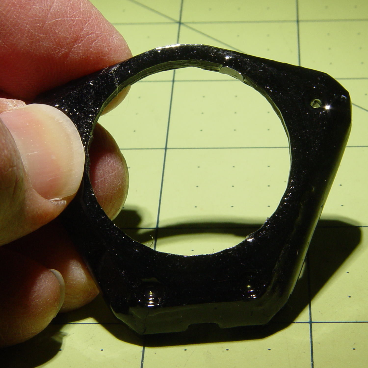
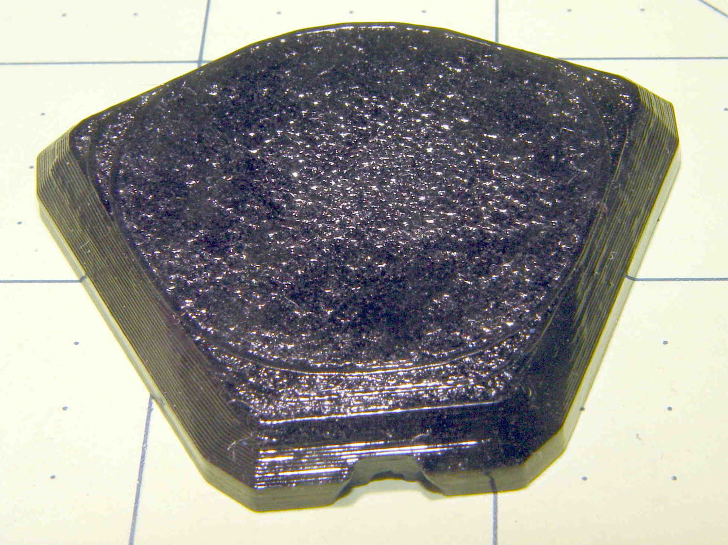
    Well, once again, it’s 3D printing to the rescue:

    Mailing Tube Cap - top - Slic3r
    Mailing Tube Cap – top – Slic3r

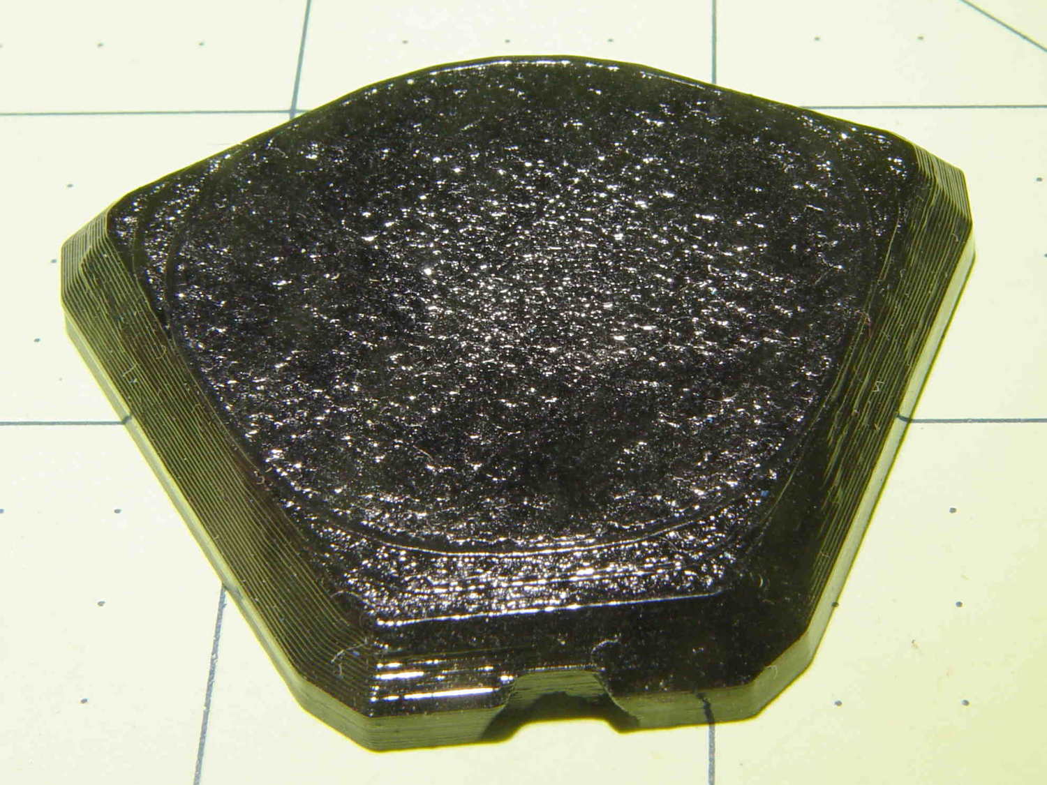
    The small ribs probably don’t actually do anything, but seemed like a nice touch.

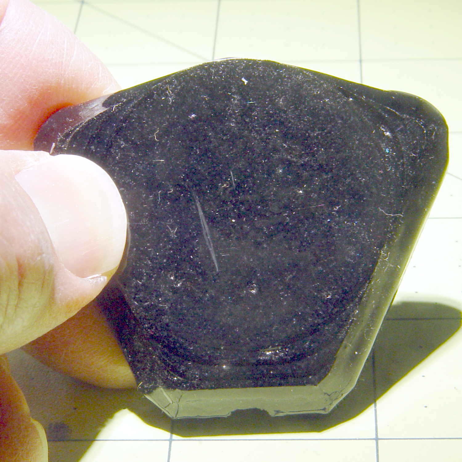
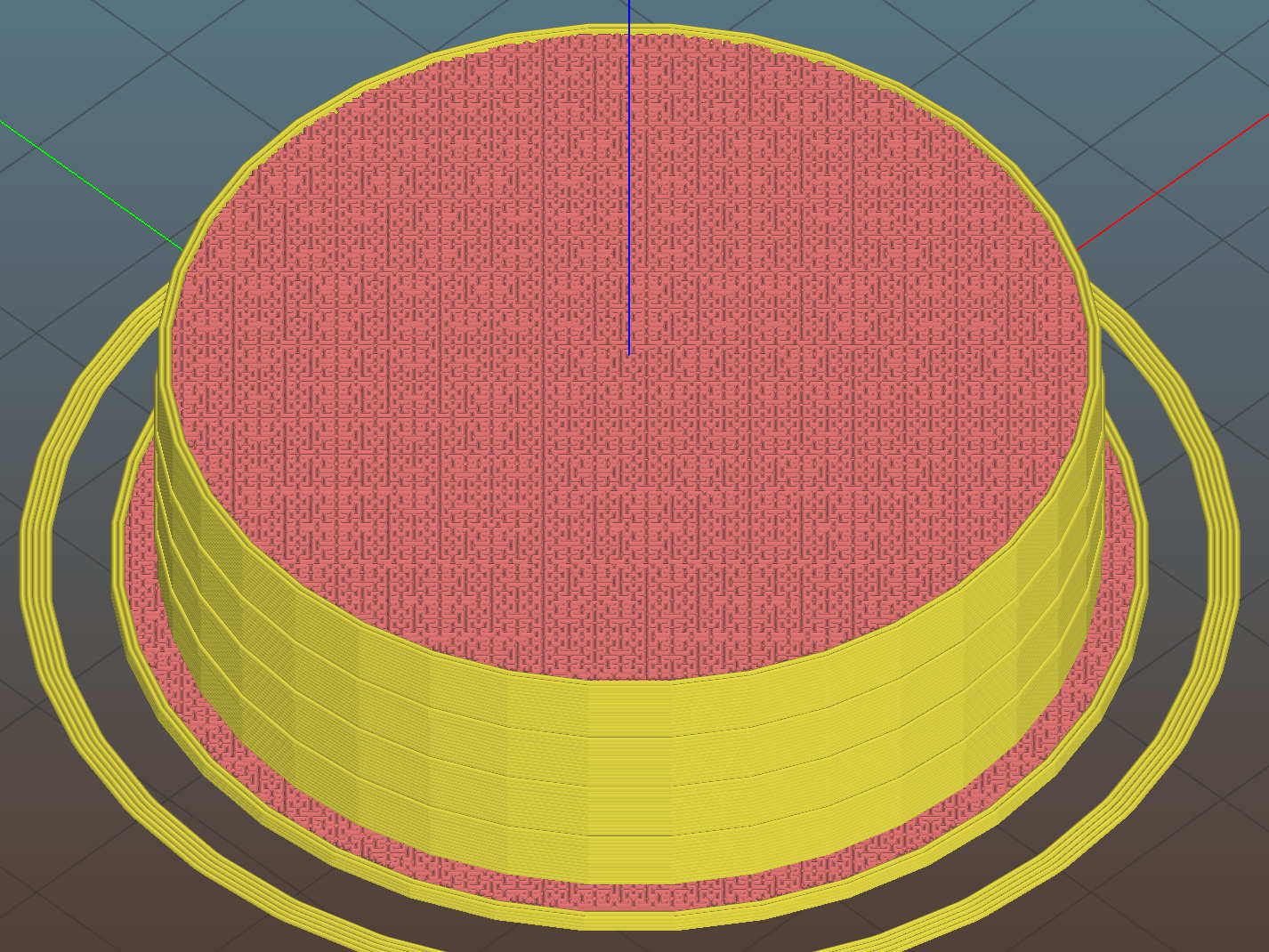
    They’re somewhat less boring from the bottom:

    Mailing Tube Cap - bottom - Slic3r
    Mailing Tube Cap – bottom – Slic3r

    The fancy spider supports that big flat top and provides some crush resistance. The flat flange should collect the edge of the packing tape wrapped around the ends.

    A firm shove installs them, so the size worked out perfectly:

    Mailing tube end cap - installed
    Mailing tube end cap – installed

    Add a wrap of tape to each end, affix the USPS label, and they went out with the next day’s mail, PETG hair and all.

    The OpenSCAD source code as a GitHub Gist:

    // Mailing tube end cap
    // Ed Nisley KE4ZNU – June 2017
    Layout = "Build";
    //- Extrusion parameters – must match reality!
    ThreadThick = 0.25;
    ThreadWidth = 0.40;
    function IntegerMultiple(Size,Unit) = Unit * ceil(Size / Unit);
    Protrusion = 0.1;
    HoleWindage = 0.2;
    //- Screw sizes
    inch = 25.4;
    TubeID = 2 * inch;
    TubeWall = 0.1 * inch;
    CapInsert = 15.0;
    CapRim = 1.0;
    CapWall = 3*ThreadWidth;
    NumFlanges = 3;
    FlangeHeight = 3*ThreadThick;
    FlangeWidth = ThreadWidth/2;
    FlangeSpace = CapInsert / (NumFlanges + 1);
    OAHeight = CapInsert + CapRim;
    NumRibs = 3*4;
    NumSides = 3*NumRibs;
    //- Adjust hole diameter to make the size come out right
    module PolyCyl(Dia,Height,ForceSides=0) { // based on nophead's polyholes
    Sides = (ForceSides != 0) ? ForceSides : (ceil(Dia) + 2);
    FixDia = Dia / cos(180/Sides);
    cylinder(r=(FixDia + HoleWindage)/2,h=Height,$fn=Sides);
    }
    module TubeCap() {
    difference() {
    cylinder(d=TubeID,h=OAHeight,$fn=NumSides);
    translate([0,0,CapWall])
    cylinder(d=TubeID – 2*CapWall,h=OAHeight,$fn=NumSides);
    }
    for (i=[1:NumFlanges])
    translate([0,0,i*FlangeSpace])
    difference() {
    cylinder(d=TubeID + 2*FlangeWidth,h=FlangeHeight,$fn=NumSides);
    translate([0,0,-Protrusion])
    cylinder(d=TubeID – 2*CapWall,h=FlangeHeight + 2*Protrusion,$fn=NumSides);
    }
    for (i=[0:NumRibs-1])
    rotate(i*360/NumRibs)
    translate([0,-ThreadWidth,CapWall + ThreadThick])
    cube([TubeID/2 – CapWall/2,2*ThreadWidth,CapInsert + CapRim – CapWall – ThreadThick],center=false);
    translate([0,0,CapInsert]) {
    difference() {
    cylinder(d=TubeID + 2*TubeWall,h=CapRim,$fn=NumSides);
    translate([0,0,-Protrusion])
    cylinder(d=TubeID – 3*2*CapWall,h=2*CapRim,$fn=NumSides);
    }
    }
    }
    //- Build things
    if (Layout == "Show")
    TubeCap();
    if (Layout == "Build")
    translate([0,0,OAHeight])
    rotate([180,0,0])
    TubeCap();
  • Proto Board Holder: Revised Screw Mounts

    Improving the crystal tester’s (nonexistent) grounding requires a band of copper tape around the inside of the proto board holder. Rather than cut the tape lengthwise to fit the holder, a new one will be just tall enough:

    Proto Board - 80x120 - revised inserts - Slic3r
    Proto Board – 80×120 – revised inserts – Slic3r

    While I was at it, I deleted the washer recesses, because those didn’t work out well, and fiddled the screw holes to put the inserts in from the bottom:

    Proto Board - 80x120 - revised inserts - detail - Slic3r
    Proto Board – 80×120 – revised inserts – detail – Slic3r

    Although the overhang inside the holes will be ugly, I’ll epoxy the inserts flush with the bottom and nobody will ever know.

    The copper tape now makes a tidy ground strap:

    Crystal Tester - ground strap - rear
    Crystal Tester – ground strap – rear

    With a gap in the front to eliminate the obvious loop:

    Crystal Tester - ground strap - front gap
    Crystal Tester – ground strap – front gap

    The OpenSCAD source code as a GitHub Gist:

    // Test support frame for proto boards
    // Ed Nisley KE4ZNU – Jan 2017
    // June 2017 – Add side-mount bracket, inserts into bottom
    Layout = "Frame";
    ClampFlange = true;
    Channel = false;
    //- Extrusion parameters – must match reality!
    ThreadThick = 0.25;
    ThreadWidth = 0.40;
    function IntegerMultiple(Size,Unit) = Unit * ceil(Size / Unit);
    Protrusion = 0.1;
    HoleWindage = 0.2;
    //- Screw sizes
    inch = 25.4;
    Tap4_40 = 0.089 * inch;
    Clear4_40 = 0.110 * inch;
    Head4_40 = 0.211 * inch;
    Head4_40Thick = 0.065 * inch;
    Nut4_40Dia = 0.228 * inch;
    Nut4_40Thick = 0.086 * inch;
    Washer4_40OD = 0.270 * inch;
    Washer4_40ID = 0.123 * inch;
    ID = 0;
    OD = 1;
    LENGTH = 2;
    Insert = [3.9,4.6,5.8];
    //- PCB sizes
    PCBSize = [80.0,120.0,1.6];
    PCBShelf = 1.0; // support rim under PCB
    Clearance = 2*[ThreadWidth,ThreadWidth,0];
    WallThick = 4.0;
    FrameHeight = IntegerMultiple(3/8 * inch,1.0);
    echo(str("Inner height: ",FrameHeight));
    ScrewOffset = 0.0 + Clear4_40/2;
    ScrewSites = [[-1,1],[-1,1]]; // -1/0/+1 = left/mid/right and bottom/mid/top
    OAHeight = FrameHeight + Clearance[2] + PCBSize[2];
    echo(str("OAH: ",OAHeight));
    FlangeExtension = 3.0;
    FlangeThick = IntegerMultiple(2.0,ThreadThick);
    Flange = PCBSize
    + 2*[ScrewOffset,ScrewOffset,0]
    + 2*[Washer4_40OD,Washer4_40OD,0]
    + [2*FlangeExtension,2*FlangeExtension,(FlangeThick – PCBSize[2])]
    ;
    echo(str("Flange: ",Flange));
    NumSides = 4*5;
    WireChannel = [Flange[0],15.0,3.0 + PCBSize[2]];
    WireChannelOffset = [Flange[0]/2,25.0,(FrameHeight + PCBSize[2] – WireChannel[2]/2)];
    //- Adjust hole diameter to make the size come out right
    module PolyCyl(Dia,Height,ForceSides=0) { // based on nophead's polyholes
    Sides = (ForceSides != 0) ? ForceSides : (ceil(Dia) + 2);
    FixDia = Dia / cos(180/Sides);
    cylinder(r=(FixDia + HoleWindage)/2,h=Height,$fn=Sides);
    }
    //- Build things
    if (Layout == "Frame")
    difference() {
    union() { // body block
    translate([0,0,OAHeight/2])
    cube(PCBSize + Clearance + [2*WallThick,2*WallThick,FrameHeight],center=true);
    for (x=[-1,1], y=[-1,1]) { // screw bosses
    translate([x*(PCBSize[0]/2 + ScrewOffset),
    y*(PCBSize[1]/2 + ScrewOffset),
    0])
    cylinder(r=Washer4_40OD,h=OAHeight,$fn=NumSides);
    }
    if (ClampFlange) // flange for work holder
    linear_extrude(height=Flange[2])
    hull()
    for (i=[-1,1], j=[-1,1]) {
    translate([i*(Flange[0]/2 – Washer4_40OD/2),j*(Flange[1]/2 – Washer4_40OD/2)])
    circle(d=Washer4_40OD,$fn=NumSides);
    }
    }
    for (x=[-1,1], y=[-1,1]) { // screw position indexes
    translate([x*(PCBSize[0]/2 + ScrewOffset),
    y*(PCBSize[1]/2 + ScrewOffset),
    -Protrusion])
    rotate(x*y*180/(2*6))
    PolyCyl(Clear4_40,(OAHeight + 2*Protrusion),6); // screw clearance holes
    translate([x*(PCBSize[0]/2 + ScrewOffset),
    y*(PCBSize[1]/2 + ScrewOffset),
    -Protrusion])
    rotate(x*y*180/(2*6))
    PolyCyl(Insert[OD],OAHeight – PCBSize[2] – 3*ThreadThick + Protrusion,6); // inserts
    if (false)
    translate([x*(PCBSize[0]/2 + ScrewOffset),
    y*(PCBSize[1]/2 + ScrewOffset),
    OAHeight – PCBSize[2]])
    PolyCyl(1.2*Washer4_40OD,(PCBSize[2] + Protrusion),NumSides); // washer recess
    }
    translate([0,0,OAHeight/2]) // through hole below PCB
    cube(PCBSize – 2*[PCBShelf,PCBShelf,0] + [0,0,2*OAHeight],center=true);
    translate([0,0,(OAHeight – (PCBSize[2] + Clearance[2])/2 + Protrusion/2)]) // PCB pocket on top
    cube(PCBSize + Clearance + [0,0,Protrusion],center=true);
    if (Channel)
    translate(WireChannelOffset) // opening for wires from bottom side
    cube(WireChannel + [0,0,Protrusion],center=true);
    }
    // Add-on bracket to hold smaller PCB upright at edge
    PCB2Insert = [3.0,4.9,4.1];
    PCB2OC = 45.0;
    if (Layout == "Bracket")
    difference() {
    hull() // frame body block
    for (x=[-1,1]) // bosses around screws
    translate([x*(PCBSize[0]/2 + ScrewOffset),0,0])
    cylinder(r=Washer4_40OD,h=OAHeight,$fn=NumSides);
    for (x=[-1,1]) // frame screw holes
    translate([x*(PCBSize[0]/2 + ScrewOffset),0,-Protrusion])
    rotate(x*180/(2*6))
    PolyCyl(Clear4_40,(OAHeight + 2*Protrusion),6);
    for (x=[-1,1]) // PCB insert holes
    translate([x*PCB2OC/2,(Washer4_40OD + Protrusion),OAHeight/2])
    rotate([90,0,0])
    cylinder(d=PCB2Insert[OD],h=2*(Washer4_40OD + Protrusion),$fn=6);
    }

  • AD8310 Log Amp Module: Sidesaddle Bracket

    This little bracket attaches to a proto board holder, with holes for M3 inserts to mount the AD8310 log amp module:

    PCB Side Bracket - 80x120
    PCB Side Bracket – 80×120

    Thusly:

    AD8310 module bracket on proto board holder - component side
    AD8310 module bracket on proto board holder – component side

    The OLED display looks a bit faded, which seems to be an interaction between matrix refresh and camera shutter: looks just fine in person!

    Not much to see from the other side:

    AD8310 module bracket on proto board holder - solder side
    AD8310 module bracket on proto board holder – solder side

    I should have included an offset to slide it a bit forward; then I could mount it on the other end with clearance for the Nano’s USB port. Maybe next time.

    The OpenSCAD source code as a GitHub Gist:

    // Test support frame for proto boards
    // Ed Nisley KE4ZNU – Jan 2017
    // June 2017 – Add side-mount bracket
    Layout = "Bracket";
    ClampFlange = true;
    Channel = false;
    //- Extrusion parameters – must match reality!
    ThreadThick = 0.25;
    ThreadWidth = 0.40;
    function IntegerMultiple(Size,Unit) = Unit * ceil(Size / Unit);
    Protrusion = 0.1;
    HoleWindage = 0.2;
    //- Screw sizes
    inch = 25.4;
    Tap4_40 = 0.089 * inch;
    Clear4_40 = 0.110 * inch;
    Head4_40 = 0.211 * inch;
    Head4_40Thick = 0.065 * inch;
    Nut4_40Dia = 0.228 * inch;
    Nut4_40Thick = 0.086 * inch;
    Washer4_40OD = 0.270 * inch;
    Washer4_40ID = 0.123 * inch;
    ID = 0;
    OD = 1;
    LENGTH = 2;
    Insert = [3.9,4.6,5.8];
    //- PCB sizes
    PCBSize = [80.0,120.0,1.6];
    PCBShelf = 1.5;
    Clearance = 2*[ThreadWidth,ThreadWidth,0];
    WallThick = 4.0;
    FrameHeight = 8.0;
    ScrewOffset = 0.0 + Clear4_40/2;
    ScrewSites = [[-1,1],[-1,1]]; // -1/0/+1 = left/mid/right and bottom/mid/top
    OAHeight = FrameHeight + Clearance[2] + PCBSize[2];
    echo(str("OAH: ",OAHeight));
    FlangeExtension = 3.0;
    FlangeThick = IntegerMultiple(2.0,ThreadThick);
    Flange = PCBSize
    + 2*[ScrewOffset,ScrewOffset,0]
    + 2*[Washer4_40OD,Washer4_40OD,0]
    + [2*FlangeExtension,2*FlangeExtension,(FlangeThick – PCBSize[2])]
    ;
    echo(str("Flange: ",Flange));
    NumSides = 4*5;
    WireChannel = [Flange[0],15.0,3.0 + PCBSize[2]];
    WireChannelOffset = [Flange[0]/2,25.0,(FrameHeight + PCBSize[2] – WireChannel[2]/2)];
    //- Adjust hole diameter to make the size come out right
    module PolyCyl(Dia,Height,ForceSides=0) { // based on nophead's polyholes
    Sides = (ForceSides != 0) ? ForceSides : (ceil(Dia) + 2);
    FixDia = Dia / cos(180/Sides);
    cylinder(r=(FixDia + HoleWindage)/2,h=Height,$fn=Sides);
    }
    //- Build things
    if (Layout == "Frame")
    difference() {
    union() { // body block
    translate([0,0,OAHeight/2])
    cube(PCBSize + Clearance + [2*WallThick,2*WallThick,FrameHeight],center=true);
    for (x=[-1,1], y=[-1,1]) { // screw bosses
    translate([x*(PCBSize[0]/2 + ScrewOffset),
    y*(PCBSize[1]/2 + ScrewOffset),
    0])
    cylinder(r=Washer4_40OD,h=OAHeight,$fn=NumSides);
    }
    if (ClampFlange) // flange for work holder
    linear_extrude(height=Flange[2])
    hull()
    for (i=[-1,1], j=[-1,1]) {
    translate([i*(Flange[0]/2 – Washer4_40OD/2),j*(Flange[1]/2 – Washer4_40OD/2)])
    circle(d=Washer4_40OD,$fn=NumSides);
    }
    }
    for (x=[-1,1], y=[-1,1]) { // screw position indexes
    translate([x*(PCBSize[0]/2 + ScrewOffset),
    y*(PCBSize[1]/2 + ScrewOffset),
    -Protrusion])
    rotate(x*y*180/(2*6))
    PolyCyl(Clear4_40,(OAHeight + 2*Protrusion),6); // screw clearance holes
    translate([x*(PCBSize[0]/2 + ScrewOffset),
    y*(PCBSize[1]/2 + ScrewOffset),
    OAHeight – PCBSize[2] – Insert[LENGTH]])
    rotate(x*y*180/(2*6))
    PolyCyl(Insert[OD],Insert[LENGTH] + Protrusion,6); // inserts
    translate([x*(PCBSize[0]/2 + ScrewOffset),
    y*(PCBSize[1]/2 + ScrewOffset),
    OAHeight – PCBSize[2]])
    PolyCyl(1.2*Washer4_40OD,(PCBSize[2] + Protrusion),NumSides); // washers
    }
    translate([0,0,OAHeight/2]) // through hole below PCB
    cube(PCBSize – 2*[PCBShelf,PCBShelf,0] + [0,0,2*OAHeight],center=true);
    translate([0,0,(OAHeight – (PCBSize[2] + Clearance[2])/2 + Protrusion/2)]) // PCB pocket on top
    cube(PCBSize + Clearance + [0,0,Protrusion],center=true);
    if (Channel)
    translate(WireChannelOffset) // opening for wires from bottom side
    cube(WireChannel + [0,0,Protrusion],center=true);
    }
    // Add-on bracket to hold smaller PCB upright at edge
    PCB2Insert = [3.0,4.9,4.1];
    PCB2OC = 45.0;
    if (Layout == "Bracket")
    difference() {
    hull() // frame body block
    for (x=[-1,1]) // bosses around screws
    translate([x*(PCBSize[0]/2 + ScrewOffset),0,0])
    cylinder(r=Washer4_40OD,h=OAHeight,$fn=NumSides);
    for (x=[-1,1]) // frame screw holes
    translate([x*(PCBSize[0]/2 + ScrewOffset),0,-Protrusion])
    rotate(x*180/(2*6))
    PolyCyl(Clear4_40,(OAHeight + 2*Protrusion),6);
    for (x=[-1,1]) // PCB insert holes
    translate([x*PCB2OC/2,(Washer4_40OD + Protrusion),OAHeight/2])
    rotate([90,0,0])
    cylinder(d=PCB2Insert[OD],h=2*(Washer4_40OD + Protrusion),$fn=6);
    }

  • Bathroom Door Retainer

    The weather got warm enough to open the windows before pollen season started, which led to the front bathroom door slamming closed in the middle of the night when a gusty rainstorm blew through town. After far too many years, I decided this was an annoyance up with which I need no longer put.

    A few minutes with OpenSCAD and Slic3r produces the shape:

    Bathroom Door Retainer - Slic3r
    Bathroom Door Retainer – Slic3r

    It’s basically an extrusion of a 2D shape with a rectangular recess for the door chewed out.

    An hour later, it’s in full effect:

    Bathroom Door Retainer - installed
    Bathroom Door Retainer – installed

    The model now sports a little ball to secure the retainer against the towel bar:

    Bathroom Door Retainer - bump
    Bathroom Door Retainer – bump

    Maybe someday I’ll reprint it.

    That was easy …

    The cast-iron pig sometimes standing guard as a doorstop in the relatively narrow doorway poses a bit of a foot hazard, so he moves into a closet during the off season. He can now remain there, snug and comfy, until a need for ballast arises.

    The OpenSCAD source code as a GitHub Gist:

    // Bathroom Door Retainer
    // Ed Nisley KE4ZNU – May 2017
    Layout = "Show"; // Show Build
    //——-
    //- Extrusion parameters must match reality!
    ThreadThick = 0.20;
    ThreadWidth = 0.40;
    HoleWindage = 0.2;
    Protrusion = 0.1; // make holes end cleanly
    function IntegerMultiple(Size,Unit) = Unit * ceil(Size / Unit);
    //——-
    // Dimensions
    TowelBarSide = 20.5; // towel bar across flat side
    TowelBarAngle = 45; // rotation of top flat from horizontal
    DoorOffset = 16.0; // from towel bar to door
    DoorThick = 36.5;
    WallThick = 4.0; // minimum wall thickness
    RetainerDepth = 10.0; // thickness of retaining notch
    NumSides = 6*4;
    CornerRad = WallThick;
    BarClipOD = TowelBarSide*sqrt(2) + 2*WallThick;
    BarClipRad = BarClipOD/2;
    OAH = RetainerDepth + WallThick;
    module LatchPlan() {
    union() {
    linear_extrude(height=OAH,convexity=4)
    difference() {
    union() {
    circle(d=BarClipOD,$fn=NumSides);
    hull()
    for (i=[0,1], j=[0,1])
    translate([i*(BarClipRad + DoorOffset + DoorThick + WallThick – CornerRad),j*(BarClipRad – CornerRad)])
    circle(r=CornerRad,$fn=4*4);
    }
    rotate(TowelBarAngle) // towel bar shape
    square(size=TowelBarSide,center=true);
    translate([0,-TowelBarSide/sqrt(2)]) // make access slot
    rotate(-TowelBarAngle)
    square(size=[2*TowelBarSide,TowelBarSide],center=false);
    }
    translate([0,-TowelBarSide/sqrt(2),OAH/2])
    rotate([90,0,45])
    sphere(r=TowelBarSide/25,$fn=4*3);
    }
    }
    module Latch() {
    difference() {
    LatchPlan();
    translate([BarClipRad + DoorOffset,-BarClipRad/2,-Protrusion])
    cube([DoorThick,BarClipOD,RetainerDepth + Protrusion],center=false);
    }
    }
    //——-
    // Build it!
    if (Layout == "Show") {
    Latch();
    }
    if (Layout == "Build") {
    translate([0,0,OAH])
    rotate([180,0,0])
    Latch();
    }

  • XTC-3D Epoxy Coating: Results

    Having figured the mixing ratios, found the mixing trays, and donned my shop apron, I buttered up several iterations of the badge reel case to see how XTC-3D epoxy works on the little things around here.

    In all cases, I haven’t done any sanding, buffing, or primping, mostly because I’m not that interested in the final surface finish.

    A single coat produces a glossy finish with ripples from the printed threads:

    XTC-3D - Hilbert - reflective
    XTC-3D – Hilbert – reflective

    Seen straight on, without the glare, a little speck toward the lower right corner shows that cleanliness is next to impossible around here:

    XTC-3D - lines - direct
    XTC-3D – lines – direct

    An additional coat atop a Hilbert-curve upper surface comes out somewhat smoother:

    XTC-3D - Hilbert - reflective 2
    XTC-3D – Hilbert – reflective 2

    Another view, with less glare, shows the pattern a bit better:

    XTC-3D - Hilbert - reflective 1
    XTC-3D – Hilbert – reflective 1

    With no glare, the 3D Honeycomb infill shows through the surface:

    XTC-3D - Hilbert - direct
    XTC-3D – Hilbert – direct

    Coating the surface with epoxy definitely makes it more transparent / less translucent by filling in the air gaps.

    The sides of that part have only one coat and still show typical 3D printed striations.

    Three coats wipe out the striations, along with all other surface detail:

    XTC-3D - Bezel - front oblique
    XTC-3D – Bezel – front oblique

    The bolt head recesses collected enough epoxy to require reaming / milling, which certainly isn’t what you want in that situation. The bolt holes also shrank, although my usual hand-twisted drill would probably suffice to clear the epoxy.

    Another view shows a glint from the smooth surface filling the upper-right recess:

    XTC-3D - Bezel - front
    XTC-3D – Bezel – front

    Three coats definitely hides the 3D printed threads, although you can see some ridges and edges:

    XTC-3D - heavy - oblique
    XTC-3D – heavy – oblique

    The epoxy isn’t perfectly self-leveling, probably due to my (lack of) technique:

    XTC-3D - heavy - reflection
    XTC-3D – heavy – reflection

    Blowing out the contrast shows the surface finish:

    XTC-3D - heavy - direct - boost
    XTC-3D – heavy – direct – boost

    Those scratches come from fingernails, after the overnight curing time. The surface is hard, but not impervious to scratching, which is about what you’d expect for a clear epoxy.

    Slightly over-thinning the XTC-3D with denatured alcohol in a 0.7 : 0.3 : 0.3 by weight ratio produced a watery liquid that penetrated directly into the surface:

    XTC-3D - thinned - oblique
    XTC-3D – thinned – oblique

    The finish depends critically on what’s below the surface and how much epoxy you apply. I tried to spread it uniformly with a foam brush, but the center came out somewhat rougher than the outer edge:

    XTC-3D - thinned - oblique
    XTC-3D – thinned – oblique

    The striations along the sides filled in a bit, but surely not enough to satisfy anybody who worries about such things.

    A specular reflection shows the changing surface smoothness:

    XTC-3D - thinned - oblique reflective
    XTC-3D – thinned – oblique reflective

    Perhaps two coats of thinned epoxy would produce a watertight / airtight part, without changing the overall dimensions by very much. The mechanical properties depend almost entirely on the plastic-to-plastic bond, so I doubt a thin epoxy layer would improve its pressure-handling capabilities.

    Few of the parts I make will benefit from an epoxy coating and I definitely don’t want to get into post-processing the parts just to improve their looks!

  • XTC-3D Epoxy Coating

    The striations inherent in the DIY-grade 3D printing process don’t bother me all that much, but I got some XTC-3D epoxy to see what I’ve been missing. The impressive scrap pile from the badge reel holder provided test pieces:

    XTC-3D Epoxy - test pieces - holders
    XTC-3D Epoxy – test pieces – holders

    If I were serious, I’d figure out a better way to hold the parts. For now, I jammed a watch crab into the back and trapped the bezel on a watch holder, but … ick.

    Weighing the components seems the least-awful way to get the small quantities I need. The instructions recommend 100:43 by weight of resin (A) : hardener (B):

    XTC-3D Epoxy - weighing pan
    XTC-3D Epoxy – weighing pan

    For these tiny parts, 2 g + 0.9 g was way too much and 1 g + 0.4 g seemed entirely adequate. If you slowly drool resin into the pan, drool slightly less than half that much hardener, and it’ll be about as close as you can get. The hardener is much less viscous than the resin: drool carefully.

    The stuff might be self-leveling on larger parts, but on these small surfaces it’s better (IMO) to dry-brush multiple layers: you can see thicker and thinner sections in the first picture. The recoat time runs about 1-½ h.

    The instructions recommend acetone or denatured alcohol as a thinning agent, at 10 to 25% of the resin volume, with curing times up to 24 h. Alcohol seems less likely to produce Bad Results, because it won’t evaporate instantly. Neither will affect PETG, but if you’re using another plastic, keep its solvent list in mind.

    I tried alcohol with a by-weight amounts around 0.7 : 0.3 : 0.3 g, obviously overshooting both the hardener and the alcohol by a few drops. The end result resembled thick water, brushed on easily, and penetrated the surface easily.

    A first coat of thinned epoxy should fill voids and unify the surface without changing the dimensions very much, with subsequent coats leveling the striations.

    More pix after more layers and more curing …

  • Tour Easy Front Fender Clip: Heatshrink

    So: jouncing over the larg(er) potholes / pavement discontinuities / debris on the roads around here wobbulates the front fender enough to pull the stays out of those tidy 18 mm = 6 diameter deep sockets on the fender clip.

    Perhaps a generous application of heatshrink tubing will help:

    Tour Easy Front Fender Clip - heatshrink hack
    Tour Easy Front Fender Clip – heatshrink hack

    Waving a heat gun around a 3D printed part seems fraught with peril, even with PETG’s glass transition temperature around 80 °C = 175 °F, as ordinary polyolefin tubing shrinks at 140-ish °C. Aiming the hot air stream more-or-less away from the clip (and the tire!) carried the day. PLA would surely have gotten bendy.

    The proper solution surely involves screw clamps and suchlike. I really dislike fiddly hardware: I hope this hack survives.