For reasons I cannot divulge at the moment, I have undertaken a project requiring Old School punched cards, although they will never be fed through a card reader. Because we live in the future, punched cards are no longer a cheap and readily available resource; I will always deeply regret trashing an entire box back in the day.
However, living in the future does confer some advantages:
The process involves a vast number of moving parts, not all of which I fully understand, but I can (generally) produce consistent results and that must suffice. This post is an overview; I will go into the moving parts in more detail so I can remember why I did what I did.
A Python program converts a line of text into an SVG file that contains either the card’s printable contents or the paths required to cut its holes & perimeter. A handful of command-line switches determines the outcome, so you run the program twice with different switches for each line of text to get a matched pair of SVG files.
A Bash script read a text file and hands each line to the Python program, producing two SVG files for each card. It then invokes Inkscape to convert the printable SVG into a PNG image, uses Imagemagic to composite the logo behind the card contents & scale the result to make my printer’s output match the laser’s dead-on positioning, then properly position the card image in a Letter-size PNG image that’s apparently the only way to print it accurately on a punched card:
That’s not full size.
N.B.: there’s no such thing as a blank card that will be punched later, because the printed card includes the text across the top. The program also suppresses the row digits where a punch will appear, thus making slight misalignments less painful and mismatched SVG files more obvious.
Print all the card images on precut 1/3 Letter size sheets of heavy cardstock:
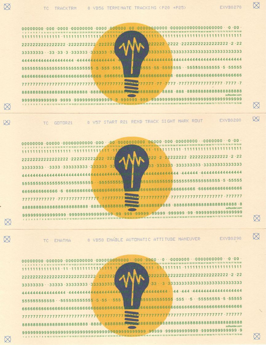
Yes, the printing on the middle card is slightly skewed with respect to the precut card blank. The overall process must handle about two millimeters of positioning inaccuracy and whatever angular skew comes from the printer’s paper feed rollers / guides.
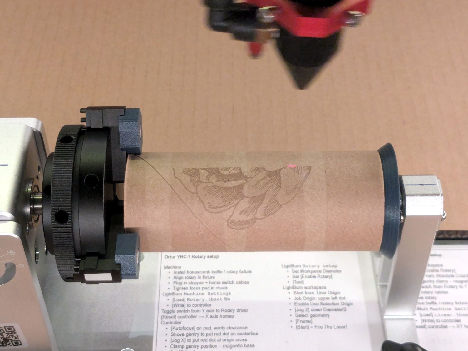
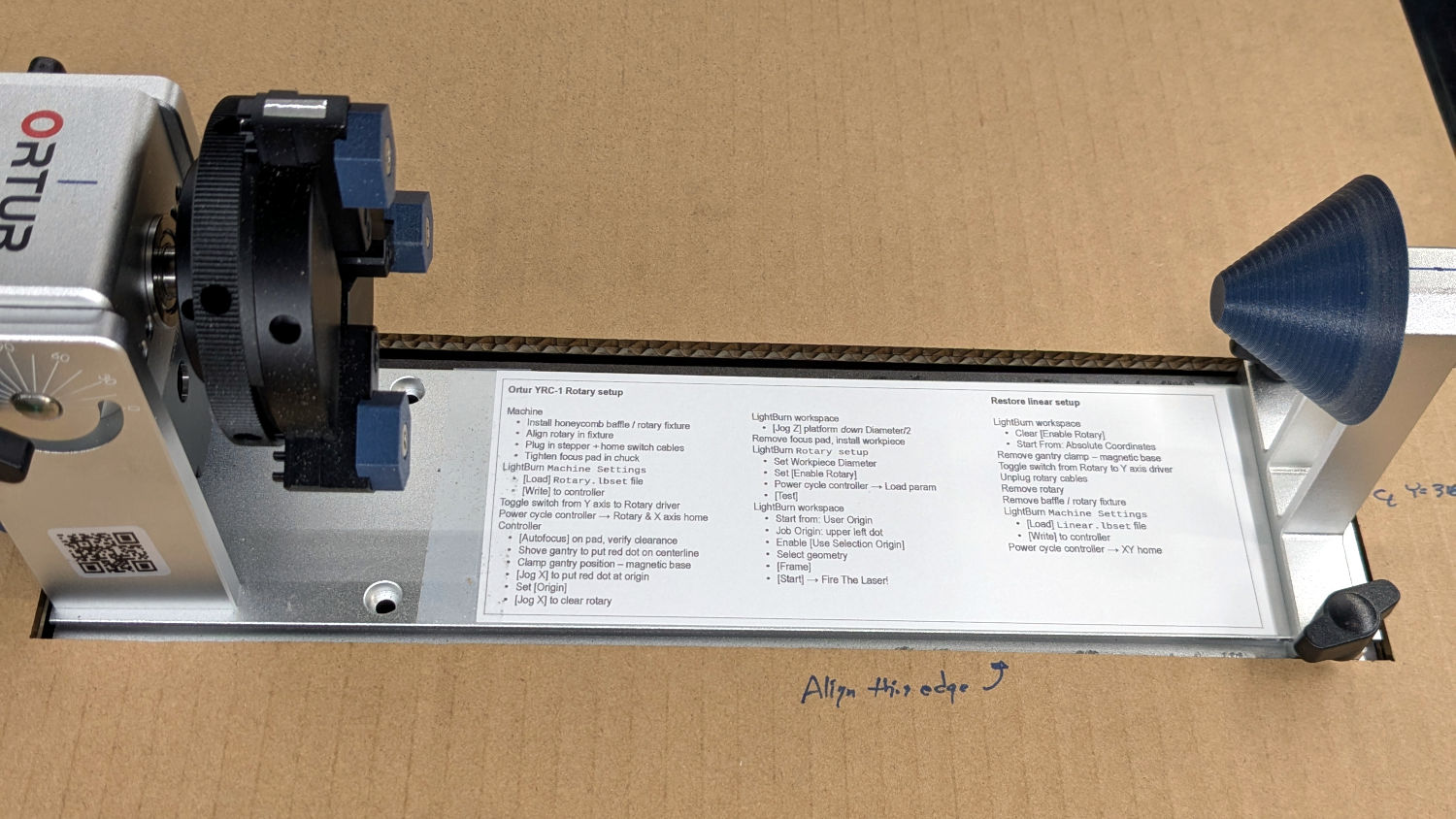
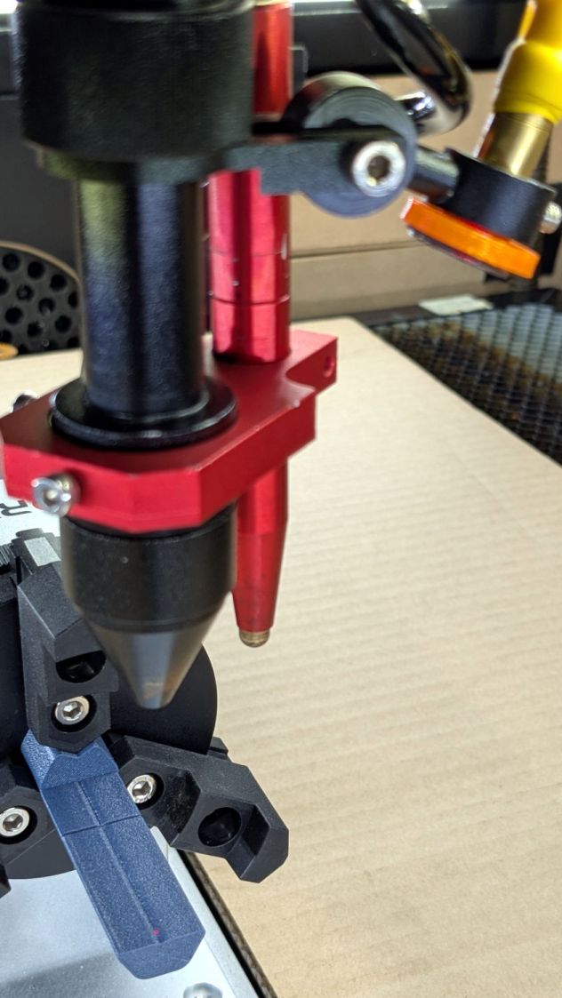
A DOS Windows BAT file feeds the SVG files with the holes & outline paths to LightBurn, one by one. No lie.
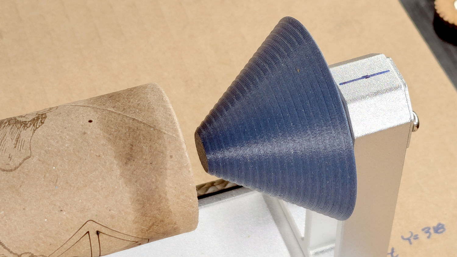
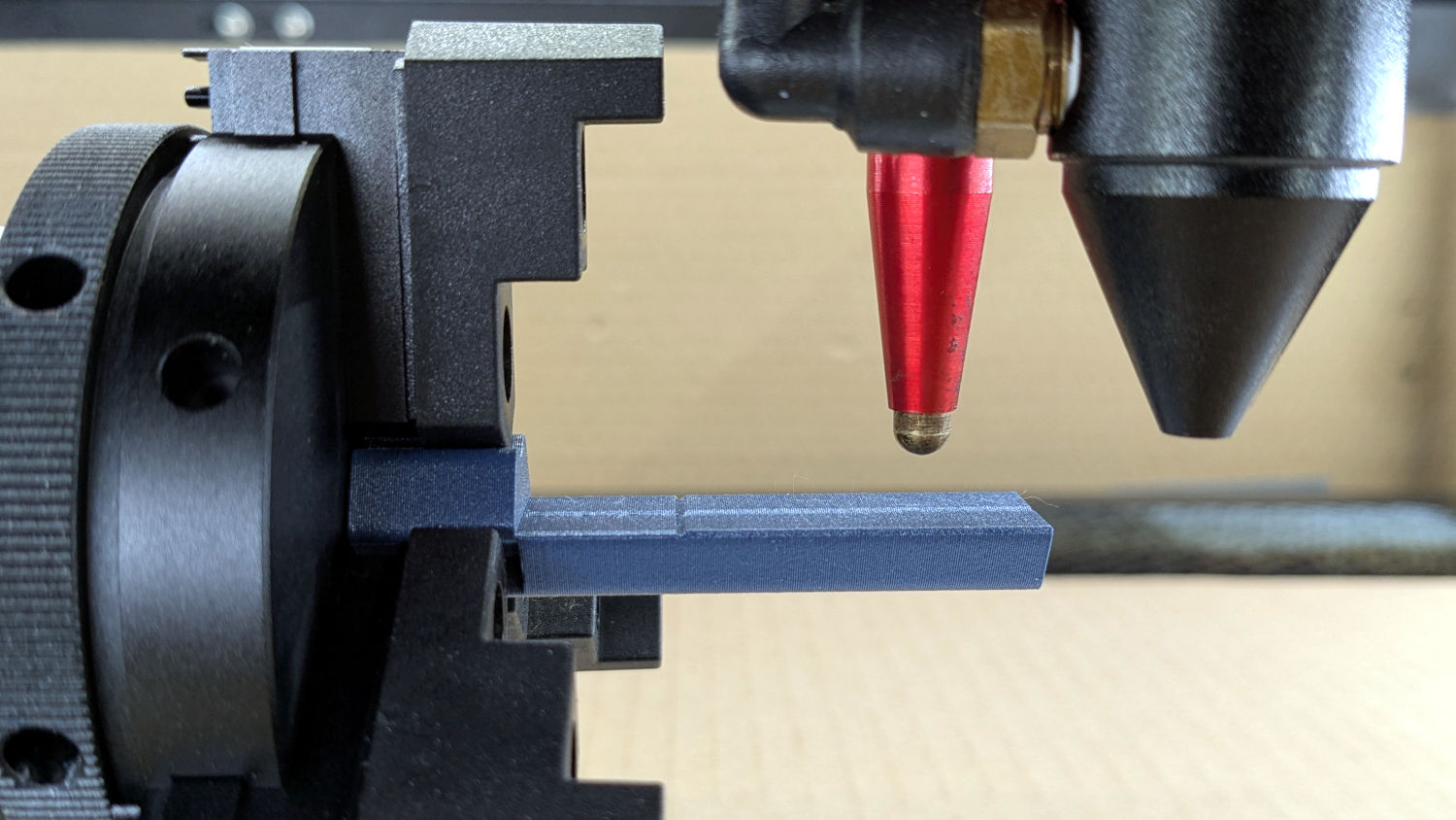
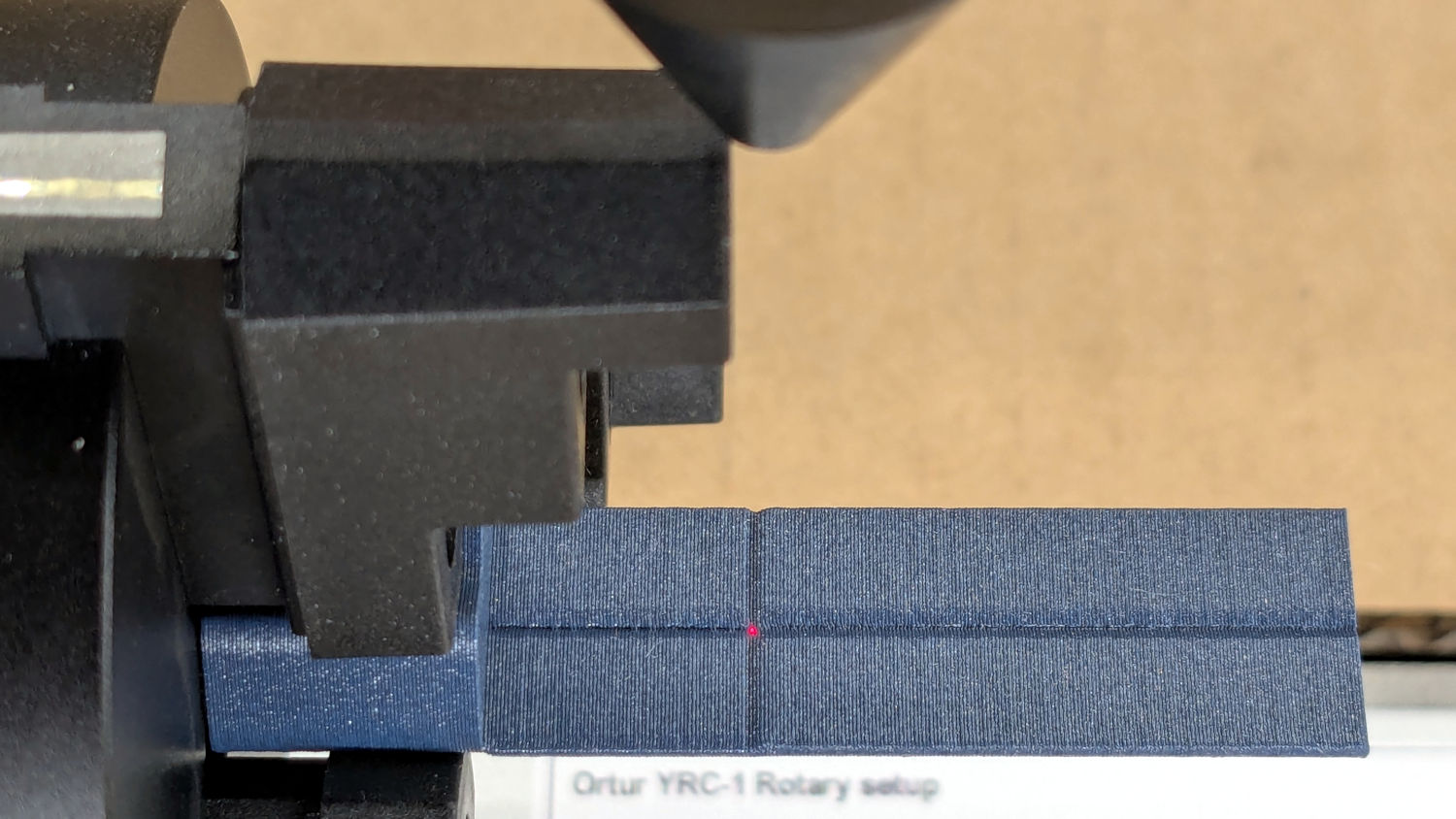
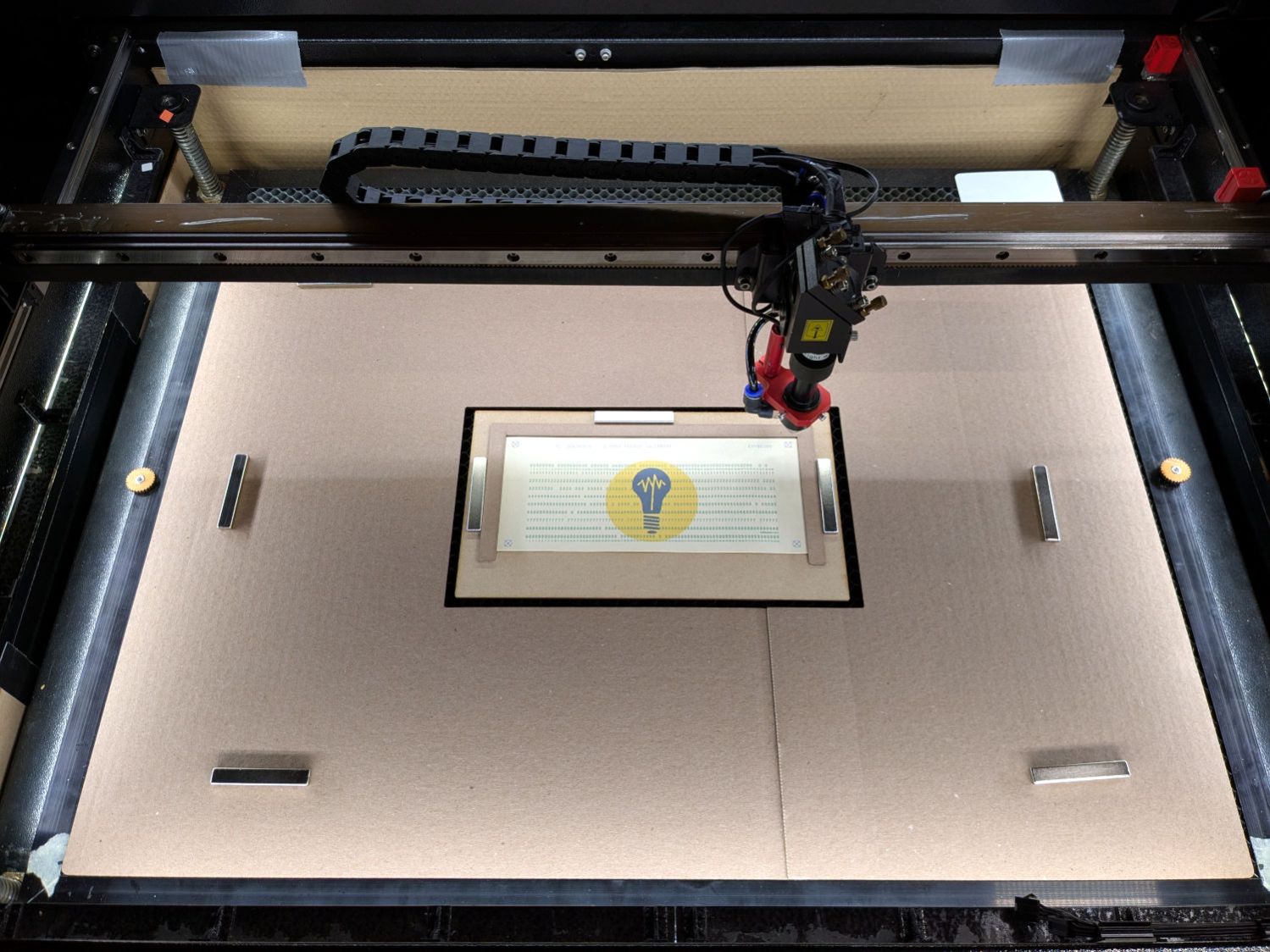
Put each printed card in a fixture and align its targets, whereupon LightBurn evaporates the holes and cuts the outline:
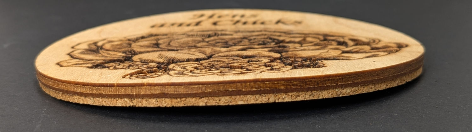
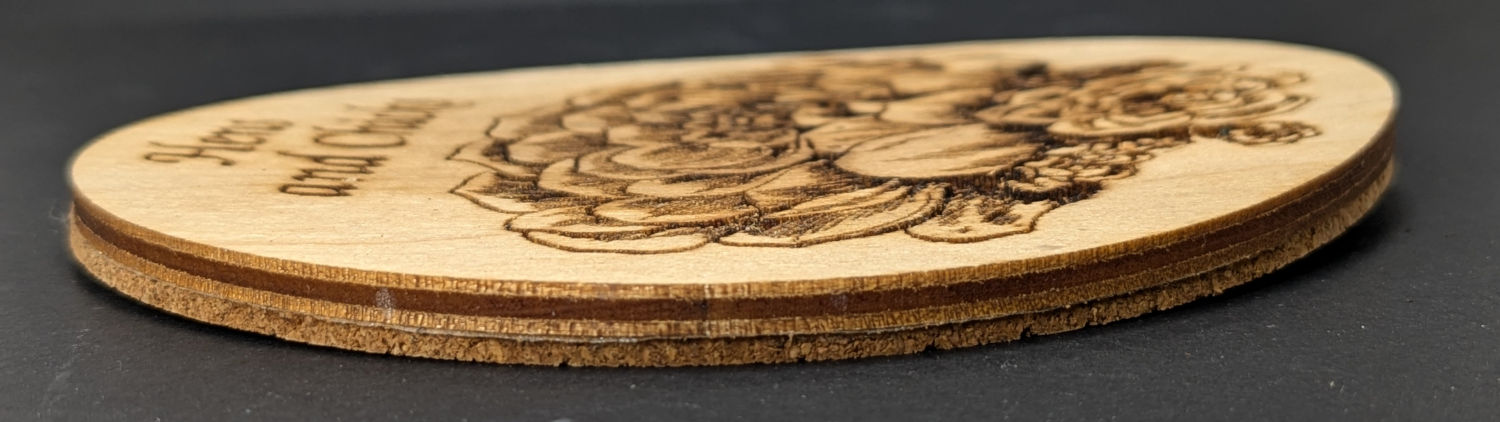
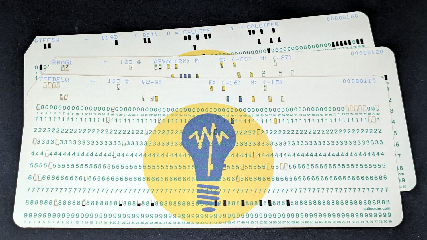
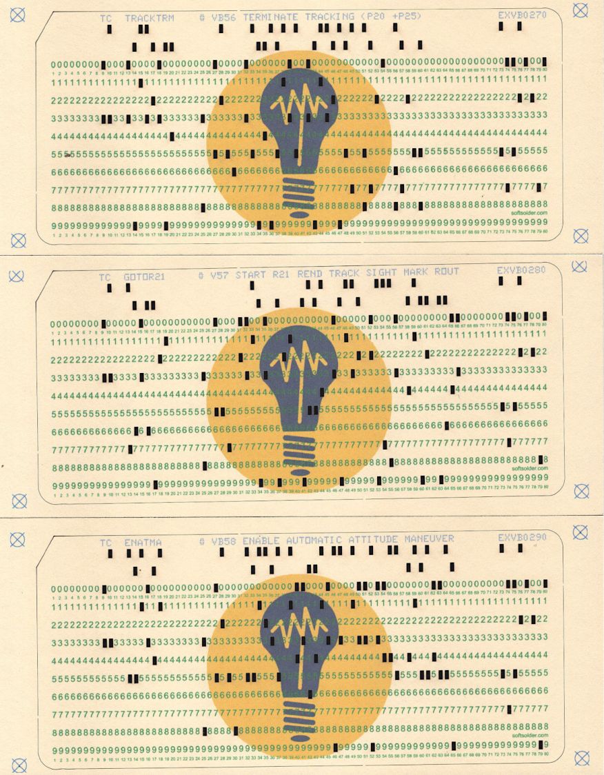
In my somewhat biased opinion, the results look good:
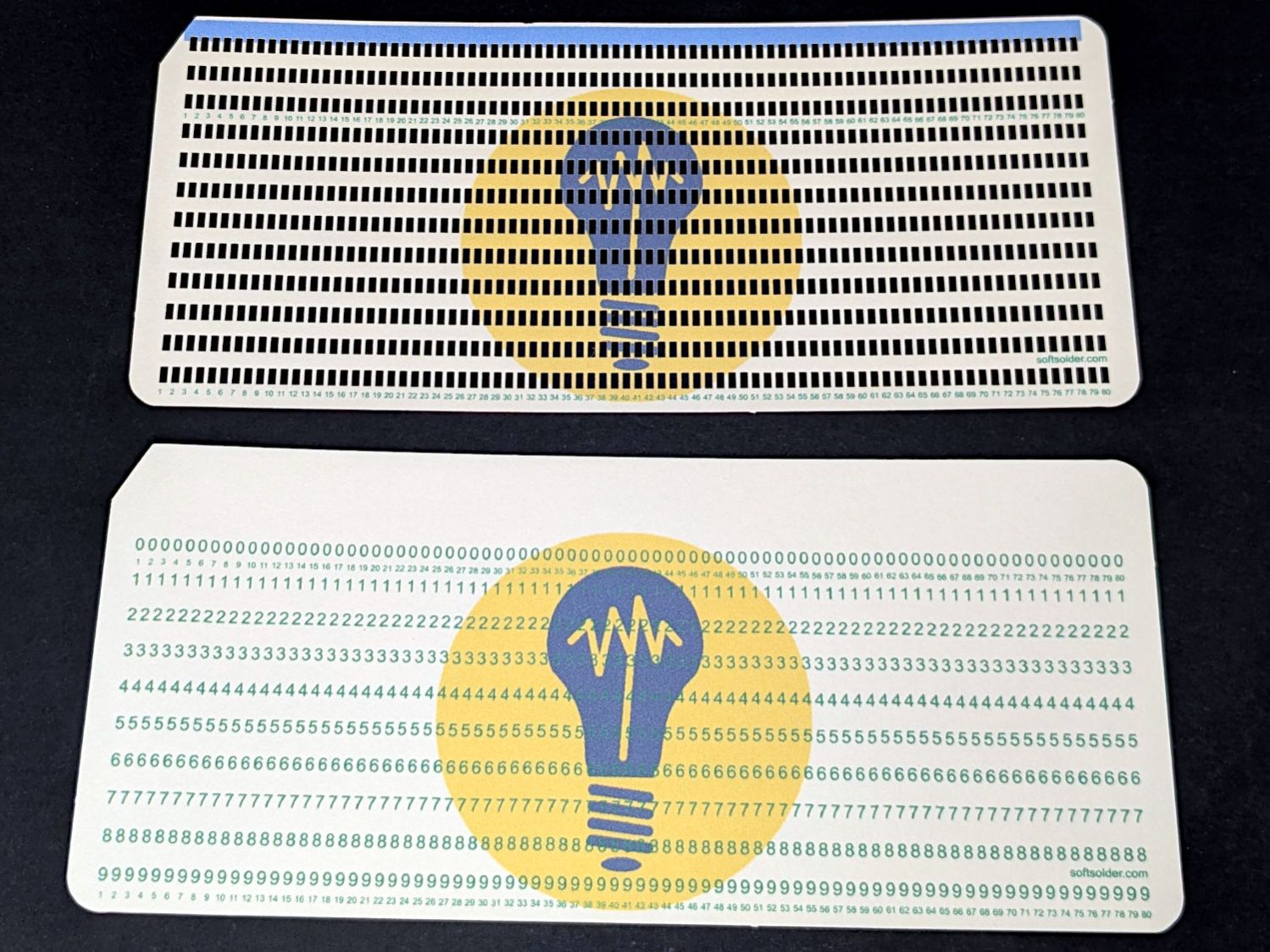
The Python program also produces cards with test patterns useful for wringing out the process:
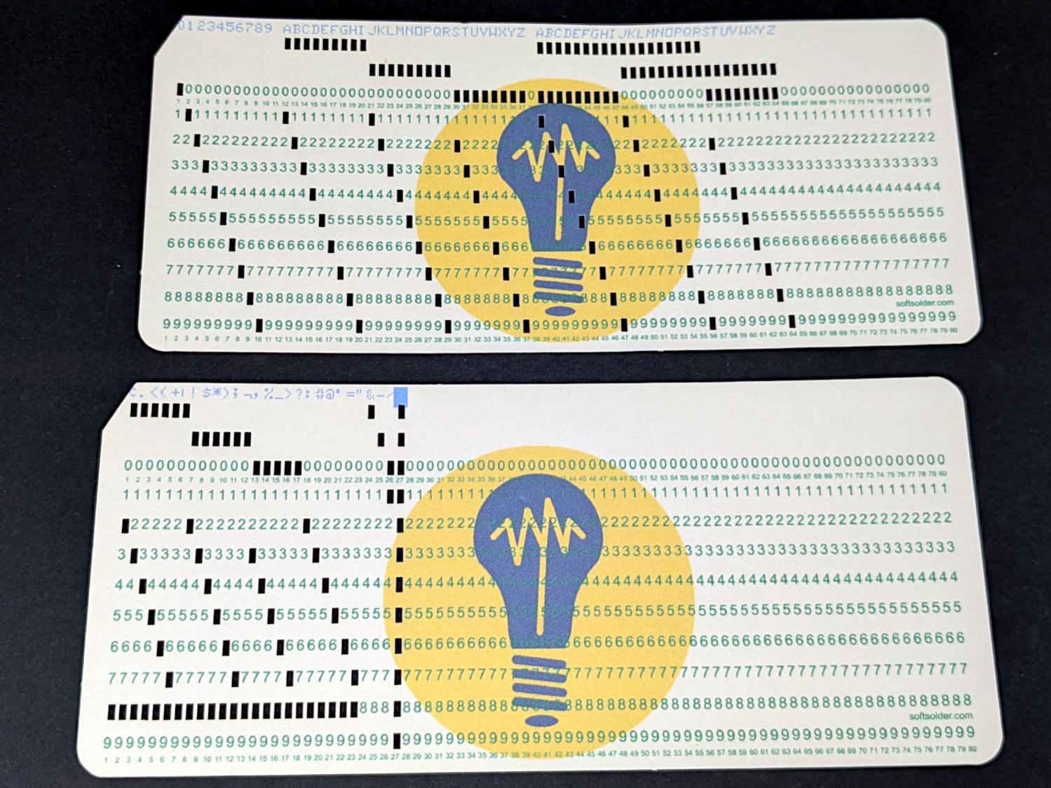
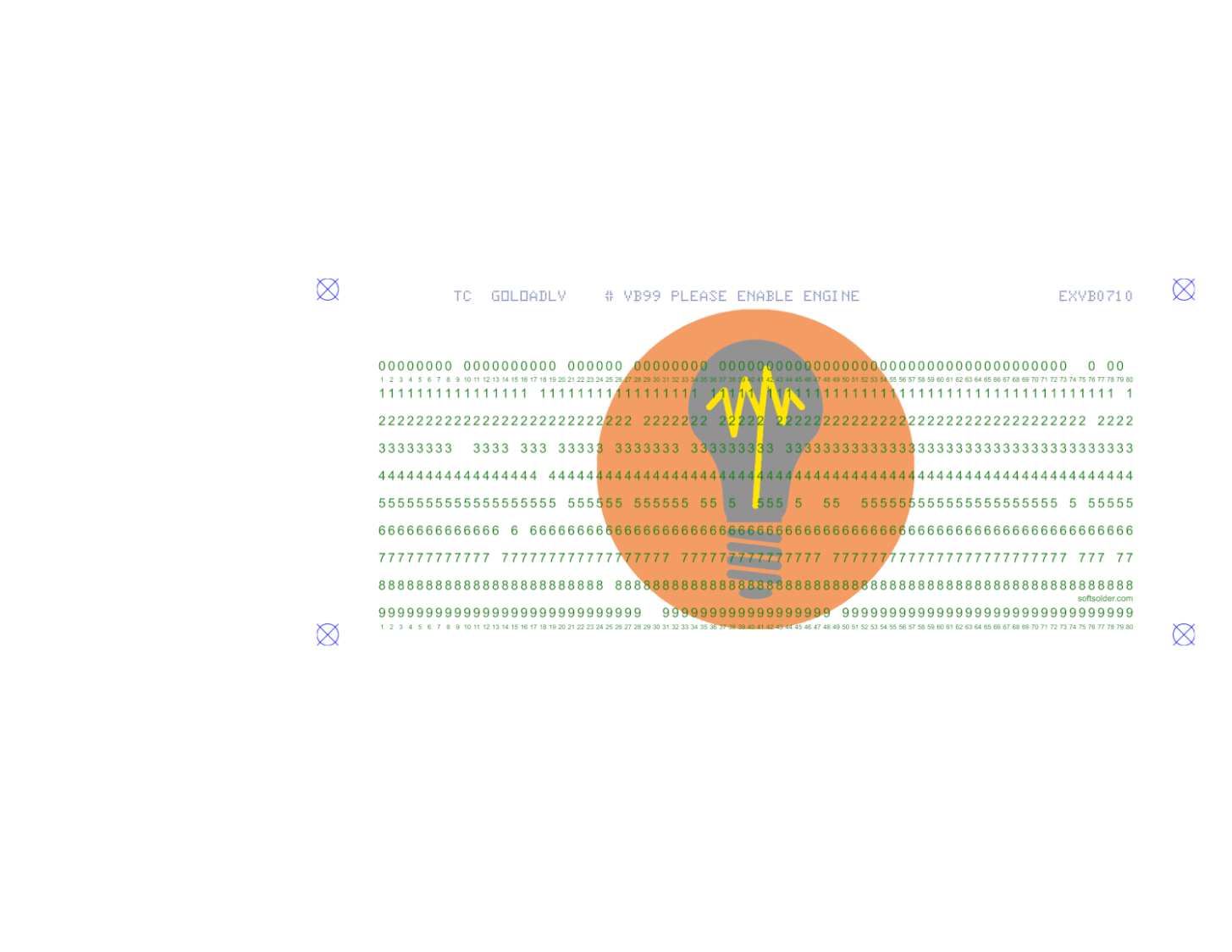
“Punching” a lace card is no problem and, given an all-blank text line, the result looks like a blank card:
If you happen to have a card punch, be my guest.
The source text for the cards comes from the Apollo Guidance Computer in the Apollo 11 Command Module, via an amazing GitHub repository. You can run a virtual AGC in the privacy & comfort of your own home.
Useful links:
- The KEYPUNCH029 dot font: thank you scruss!
- Punched card codes, of which I used EBCDIC, from a heroic collection of punched card information
- Baffling Inkscape command line doc
- Imagemagick command line options doc
- SVG doc from Mozilla
- svg.py library for making SVG files
- Python library doc
- Another punched card generator