Ed Nisley's Blog: Shop notes, electronics, firmware, machinery, 3D printing, laser cuttery, and curiosities. Contents: 100% human thinking, 0% AI slop.
Our Young Engineer knits during rare moments of downtime and sketched an idea for stitch counters to mark progress between those moments. There being nothing like a new project to take one’s mind off all of one’s previous projects:
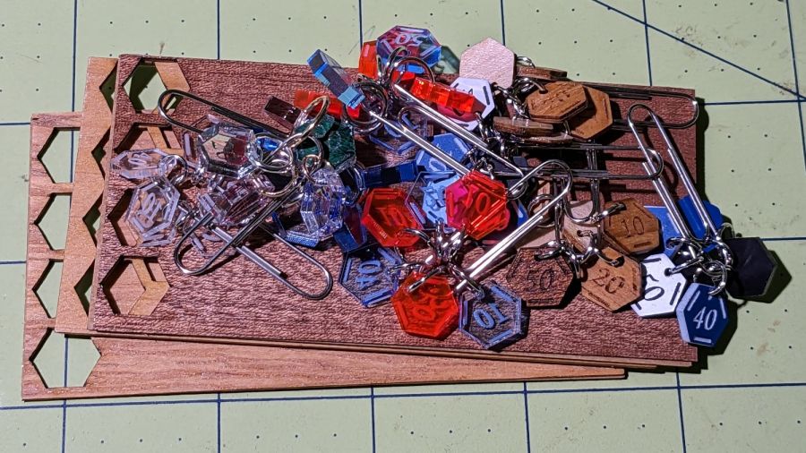
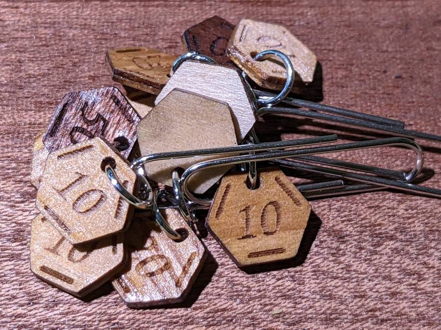
Stitch Counters – overview
These are more along the lines of feasibility / material tests than finished products, so you’ll see plenty of rough edges.
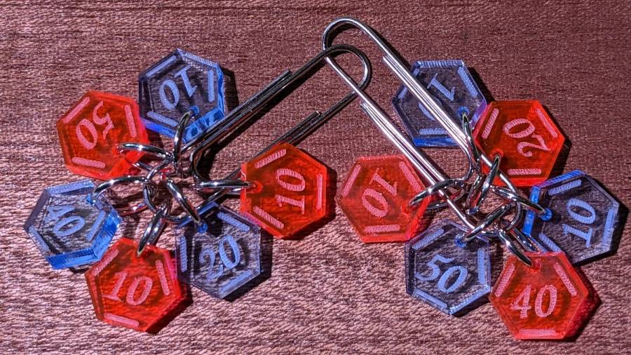
Prior to doing this, we agreed that 3 mm material was probably too thick, particularly given the small scale: the hexagons are 10 mm edge-to-edge with a 1.5 mm hole for the jump ring.
The jump rings are (mostly) 8 mm OD, which may or may not be the right diameter for all possible knitting needles.
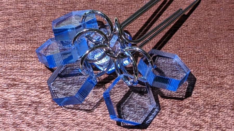
The count sequence goes 10 20 10 40 50 10 with alternating colors:
Stitch Counters – red and blue
Those came from 3 mm red and blue transparent acrylic, looking entirely too much like candy. Cutting two identical layouts from two different materials, then swapping a few counters, gives me two related-but-different sets. This idea is also subject to revision.
I like the set of 3 mm acrylic mirror counters colored with Sharpie:
Stitch Counters – mirror
Alas, the unprotected mirror backing won’t survive long in the real world and Sharpie ink tends to stress-crack the acrylic. Bonding a thin colored sheet / gel filter to the back with an adhesive sheet in between would work, although I don’t look forward to the fiddly alignment. Bonus: sticky edges are a nonstarter in this application.
A setup error produced a set of unmarked counters that might still come in handy for something:
PXL_20230507_150124595 – Stitch Counters – blue blank
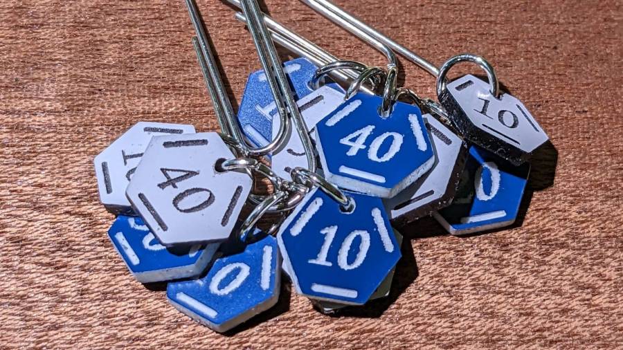
Trolase acrylic 1/16 inch = 1.5 mm sheets produce the most visible legends, in a relentlessly industrial sort of way:
Stitch Counters – Trolase
Those have a single thin layer atop a white or black base sheet, but three-layer 1.5 mm Trolase sheets with matching top and bottom colors (cladding on a white core) would look better.
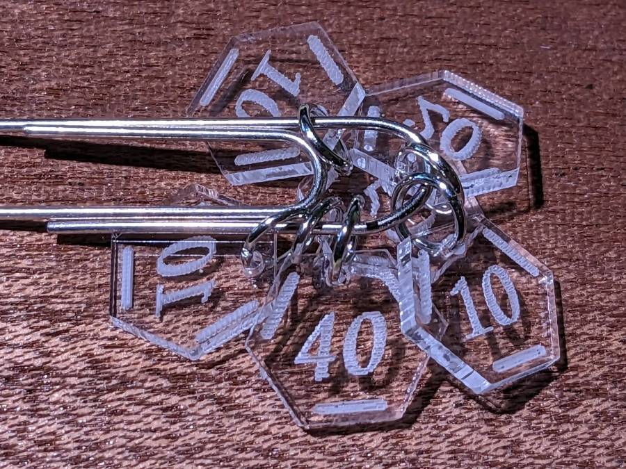
If you can’t decide on a color, go clear:
Stitch Counters – clear
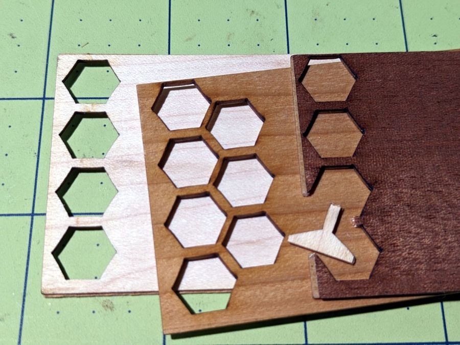
All of those appear on a background of some thin DIY plywood:
Stitch Counters – veneer plywood sheets
The bottom sheet is very pale veneer that came with a layer of genuine 3M 468 transfer tape with 200MP adhesive. I stuck three different veneers on three 100×50 mm rectangles of the stuff to make 1.5 mm thick “plywood”. The adhesive sheet provides lateral strength, not the wood fibers, so it’s not quite as easy to tear as the broken fragment would suggest.
The results look passable, although there’s room for improvement:
Stitch Counters – veneer plywood
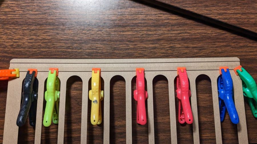
After engraving & cutting, I slathered them with clear polyurethane finish and hung them up to dry:
Stitch Counters – wood finish curing
I like the effect, but using the pale veneer for the bottom layer made them look identical from that side. Worse, two of the three top layer veneers had nearly identical colors (one has more grain) after the finish cured.
More thought seems in order, but at least I’ve explored some of the solution space.
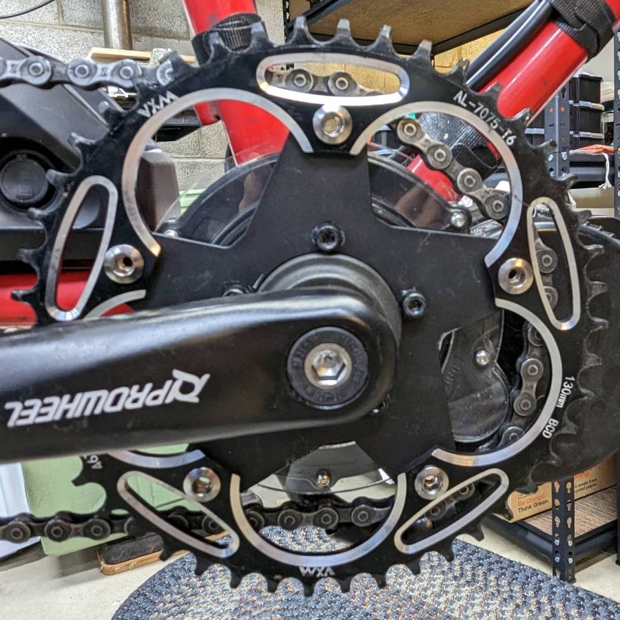
When the chain falls off the top of the chainring toward the motor, the part remaining engaged with the chainring will inevitably drag the rest into the gap between the motor and the chainring spider, whereupon it will jam firmly in place and be almost impossible to extract. Preventing this means filling the gap, which required several iterations:
Bafang motor gap filler – prototypes
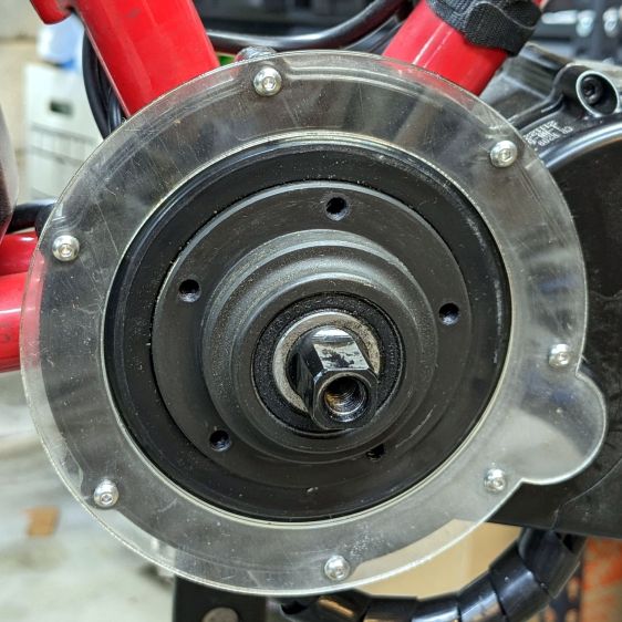
The Bafang motor has a cover held in place by seven M3 flat-head screws, shown here below a test filler using pan head screws:
Bafang motor gap filler – installed
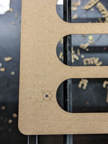
Contrary to what you might think, the five screws that obviously sit on five points of a hexagon do not in fact sit 60° apart. How you find this out is by making the obvious layout, including the two screws bracketing the pinion gear in the lower right, then applying windage:
Bafang motor housing gap filler – hole adjustments
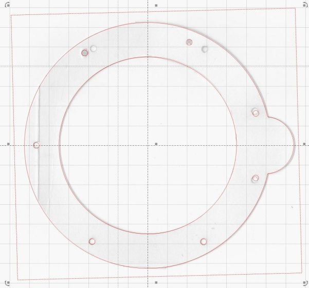
That’s one of the paper templates seen above, with laser-cut holes 60° apart and ugly holes punched at the actual screw locations. Then you scan and overlay that image with the LightBurn layout and twiddle the hole locations to make the answer come out right:
Bafang motor housing gap filler – hole adjustments – LB overlay
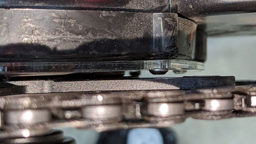
With that in hand, I cut a 1 mm acrylic shape to measure the clearance between the motor + filler and the chainring spider, with pan-head screws replacing the original flat-head screws:
Bafang motor gap filler – top view
That’s a single piece of 2.5 mm acrylic I used after discovering a pair of the 1 mm acrylic shapes fit with space to spare: hooray for rapid prototyping.
A test chain drop suggested it might suffice:
Bafang motor gap filler – test
If I were so inclined, 3 mm acrylic with countersunk holes and slightly longer flat-head screws would probably work, but I’ll use this until it fails to prevent a chain snag.
The careful observer will have noted the stress crack extending radially inward from the upper-right screw, which I am carefully avoiding doing anything about, pending the aforementioned failure.
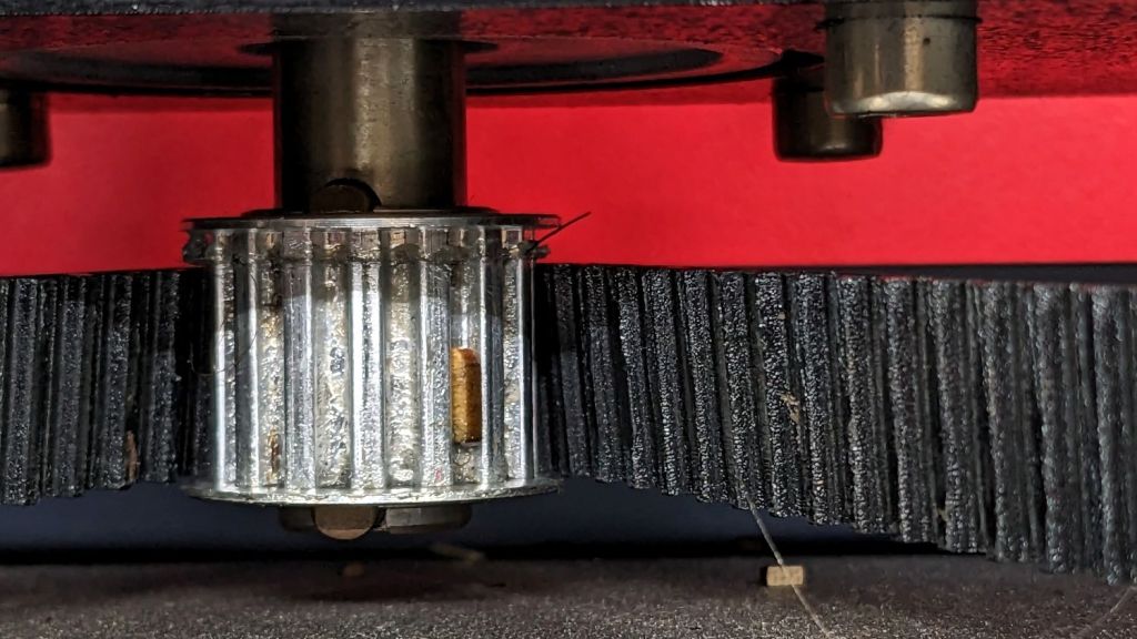
My OMTech 60 W laser cutter has a stepper motor Z axis drive that has worked flawlessly since it arrived. However, it recently developed a periodic klonk during autofocusing and manual jogging, loud enough to shake the platform and rattle the cabinet’s bottom plate.
A few minutes of poking around revealed the klonk happened on each turn of the Z axis leadscrews, which quickly led to finding the cause:
Craft Stick – swarf in belt drive
It’s a rectangular wood chip, perfectly sized to jam into the Z axis motor pulley driving the belt: a belt tooth lifts up on the chip as the pulley turns, then klonks as it slips off the other side. The motor pulley and all four leadscrew pinons have the same number of teeth, so they’re all at the same point in their rotation when the belt slams down onto the pulley.
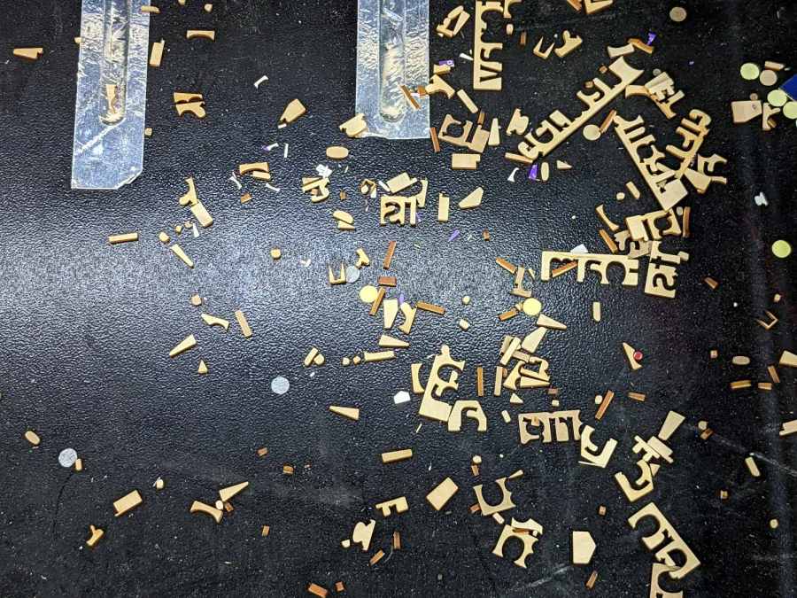
Where might such a thing come from? Well, I recently finished a batch of plant markers and hadn’t yet cleaned out the “chip tray” which is also just the bottom plate of the cabinet:
Craft Stick – swarf
I briefly considered building a guard for the motor pulley, but the belt most likely carried it from elsewhere. The leadscrews have an ample coating of grease that was also smeared elsewhere on the cabinet, making the belt sticky enough to catch such things.
The chip tray is once again pretty clean and the platform behaves normally again.
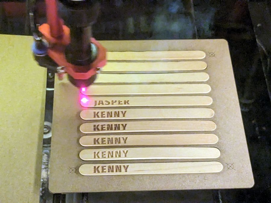
Jog the laser to the upper-right target on the fixture, click the upper-right target in the template, and tell P-n-C that’s the First Target. Jog to the lower-left target, click the lower left target, and that’s the Second P-n-C Target:
Craft Stick Markers – fixture target detail
The colored circles indicate the targets on the template:
Craft Stick Markers – LB PnC layout
Select the Align No Scaling option, because the template and the fixture are exactly the same size.
Click-n-drag to select the entire template (because you should always use Cut Selected Graphics), then frame it Just To Be Sure. The red dot pointer (or whatever you use) should kiss the fixture’s perimeter all the way around.
Make sure the fill layer happens before the cut layer, then Release The Laser:
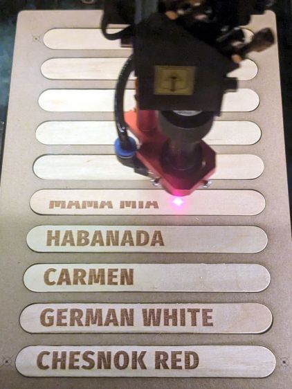
Craft Stick Markers – engraving
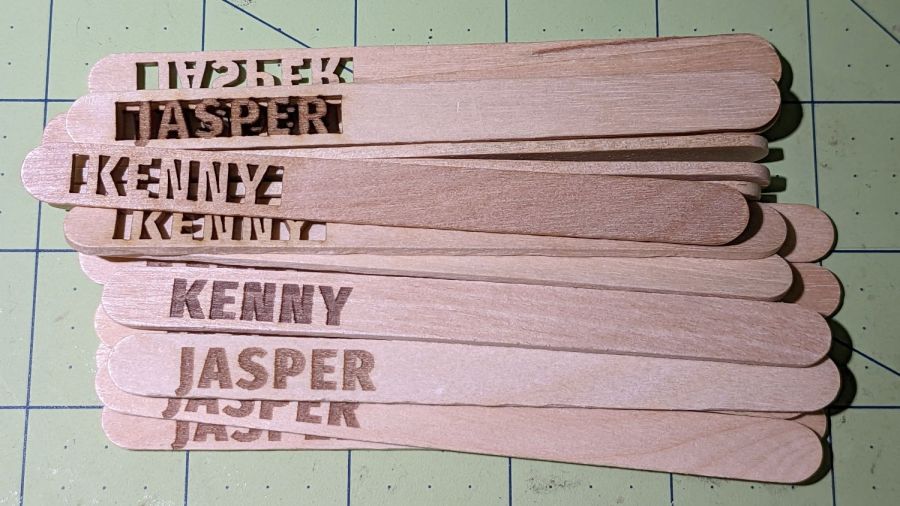
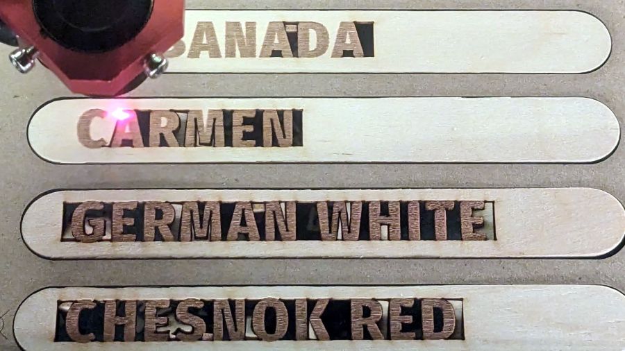
The cut layer trims around the engraved letters to leave them standing in the rectangle:
Craft Stick Markers – cutting
Some of the smaller bits won’t fall out as they’re cut, but a sharp thwack ejects them easily enough.
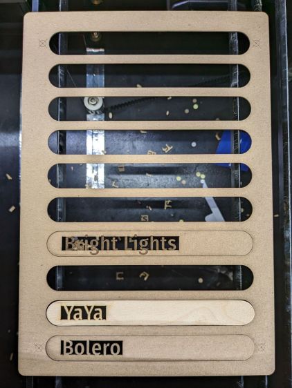
Producing a set of ten sticks takes maybe seven minutes:
Craft Stick Markers – fixture second fill
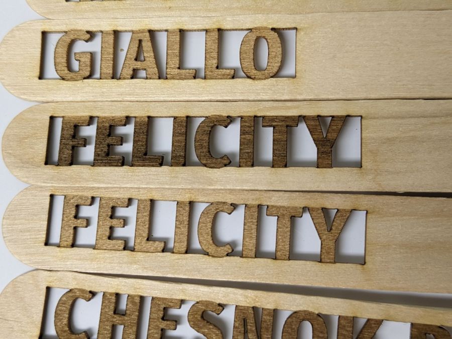
Because craft sticks aren’t intended for fine woodworking, don’t expect consistent engraving results:
Craft Stick Markers – wood engraving difference
Applying a finish would definitely improve their appearance, but most such chemicals don’t belong in an organic vegetable garden.
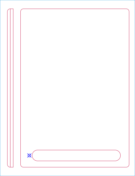
Putting the entire fixture layout onto a tool layer produces a template to align the text on the sticks:
Craft Stick Plant Markers – fixture layout
The rectangles mark where you put cut layer rectangles around the text in each stick. The sticks are 18 mm wide, so a 10 mm cutout leaves what should be enough wood along the edges. The rectangle length is a serving suggestion, as you must adjust the cut rectangle to fit the text.
Group everything except the four targets into a single object so you won’t inadvertently move only a part of it. The targets must remain separate to work with the Print-and-Cut alignment. With that set up, Lock the position of the entire layout to prevent you from moving any part of it.
Starting with a blank tag in the template:
Craft Stick Markers – LB template – base
Draw a rectangle in a cut layer to match the template, which is easy if you have Object Snap set up properly:
Craft Stick Markers – LB template – rectangle
Add your text in a chunky font like Fira Sans Condensed Heavy, set to 15 mm tall with 5 mm horizontal spacing:
Craft Stick Markers – LB template – lowercase text
LightBurn aggressively snaps a new text cursor to the nearest pre-existing text, so you may be forced to click far away from where you want to place the text, type the text, then move the finished string. LightBurn will also snap the text to the display grid as you drag it around, so hold the Ctrl key down to disable snapping while you eyeball the proper alignment with the rectangle. Leave about 2 mm between the left edge of the rectangle and the first letter to make an easily visible space.
Although you can use lowercase letters, uppercase letters have the compelling advantage of being attached both top and bottom, so retype the text if you forgot about the Caps Lock key:
The 15 mm font height I’m using seems to be the overall maximum from the top of the tallest letter to the bottom of the lowest descender, not the height of any specific capital letter, all of which extend beyond the cut rectangle by about half a millimeter. That’s crucial to make this thing work, so tune the font and its height appropriately.
Select the text string when you have it properly aligned:
Craft Stick Markers – LB template – text selected
Hit Ctrl-D to duplicate the text, tap the ↑ (Up) arrow key to move the copy out of the way, and set it to the fill layer.
Now the magic happens.
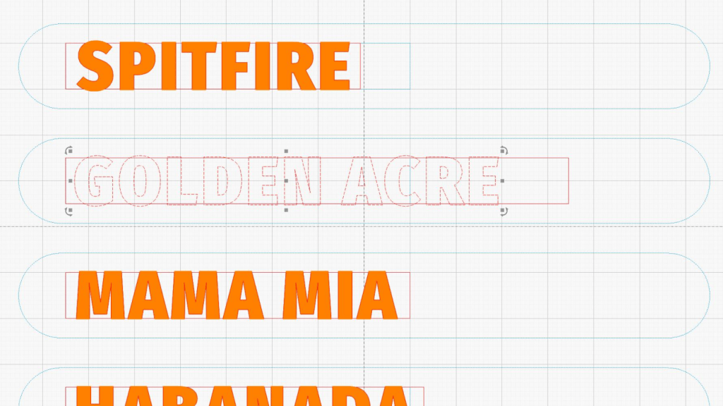
Select the rectangle, Shift-select the text, and Boolean Subtract (Alt minus) the text from the rectangle:
Craft Stick Markers – LB template – subtracted text
Realize that you have screwed up by not shortening the right side of the rectangle to leave about 2 mm of open space. Bang on Ctrl-Z to undo the last step, shorten the rectangle, Shift-select the text again, then subtract the text from the rectangle:
Craft Stick Markers – LB template – properly subtracted text
Select the filled copy and whack the ↓ (Down) arrow key to move it back over the cut layer:
Craft Stick Markers – LB template – overlaid text
Now the filled layer will toast the characters to a nice brown and the cut layer will remove the background rectangle.
After finishing the text dance for all the markers, the template should look something like this:
Craft Stick Markers – LB PnC layout
The cheerful circles come from LightBurn’s Print-and-Cut Wizard aligning the template with the fixture holding the craft sticks on the laser platform, about which more tomorrow.
A good rule of thumb says never do any more work than absolutely necessary, so the rest of the fixture comes from linear arrays replicating the stick slots and targets:
Craft Stick Plant Markers – fixture cut layout – full
The two strips over on the left (with a common cut down the middle) get glued to the underside of the fixture:
Craft Stick Markers – fixture rail gluing
They’re exactly 5 mm apart to bracket one of the knife-edge bars supporting the fixture. The bar is upside-down to put its flat side upward:
Craft Stick Markers – fixture target detail
Yes, the fixture is made of chipboard, mostly because it’s about the same thickness as a craft stick and it’s cheap & readily available. Each target gets an ink blot to make it more conspicuous; there is also a tiny hole burned through the chipboard at the center to mark the other side for the strips.
Two knife-edge bars (sharp side up) support the sticks near their ends, well out of the cutting path, to prevent scorch marks:
Craft Stick Markers – fixture overview
It’s worth noting the knife-edge bars are 5 mm wide and the platform spaces them on 3/8 inch = 9.525 mm centers. Not 10 mm, not 9.5 mm, exactly 3/8 inch. Kinda like the platform leadscrews: a 4 mm lead thread driven by a belt with 0.2 inch pitch. Only in America.
This doodle captures the key dimensions down there in the corner to work out where the strips should go:
Craft Stick Plant Markers – fixture vs laser bar spacing doodle
Now, to convert names from a garden map into plant markers …


