
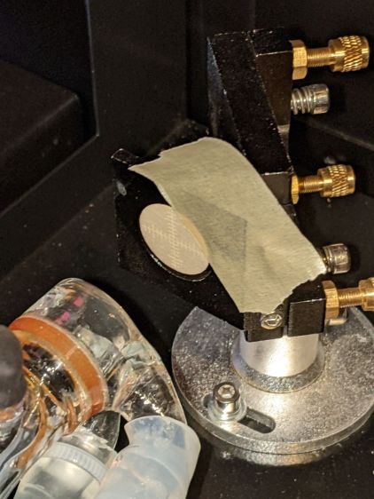
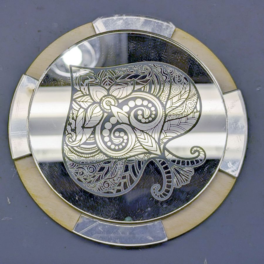
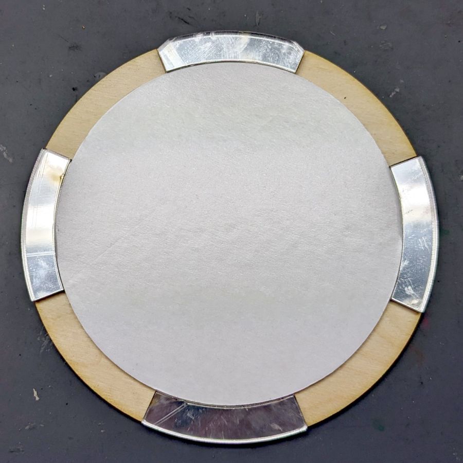
Although the most recent mirror alignment exercise put the laser beam parallel to the axes and centered in the aperture perpendicular to the beam, a target directly on Mirror 2 showed the beam was badly off-center:
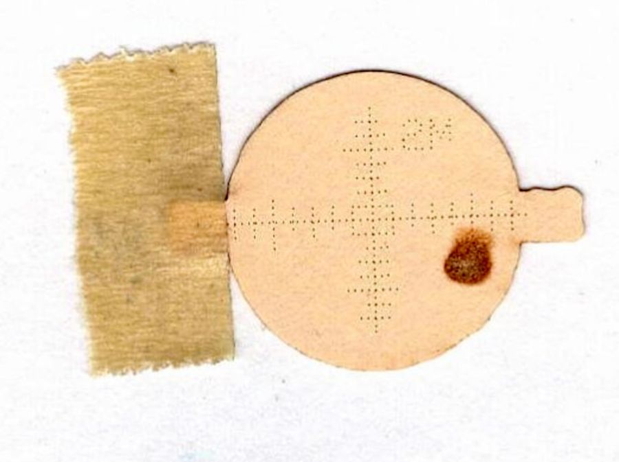
Because that target is sitting flat on the mirror, the beam appears wider than it is tall. The horizontal graticule divisions are 1.4 mm apart to allow direct measurements: the spot is really circular and 3 mm in diameter.
Poking around inside the cabinet reminded me that all of the mirrors sat with their adjustments jammed at one end of their range, rather than being more-or-less centered.
Mirror 2, in particular, was up against all three limits. The slots behind these two screws allow the mount to slide along the X axis:
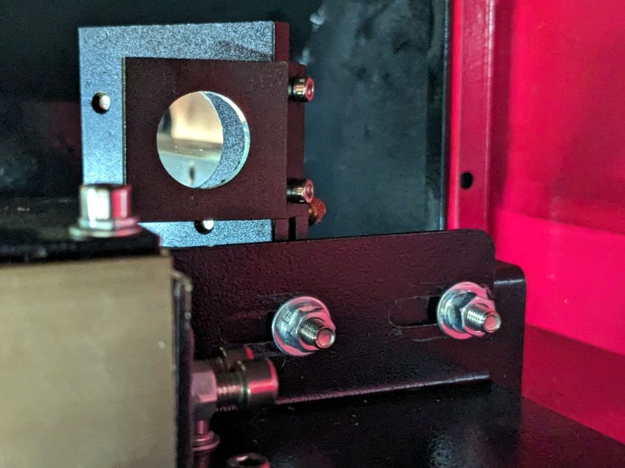
Seen from the front of the cabinet, those same two screws set the mirror position in the Z axis:

As you may imagine, using those two screws to secure the mirror at a specific location in both X and Z at the same time is … challenging.
The two screws directly under the mirror set its position along the Y axis and allow a slight rotation around Z to fine-tune the alignment of the perpendicular aperture used for mirror alignment; unlike the other two axes, the mirror wasn’t jammed against the end of the slots.
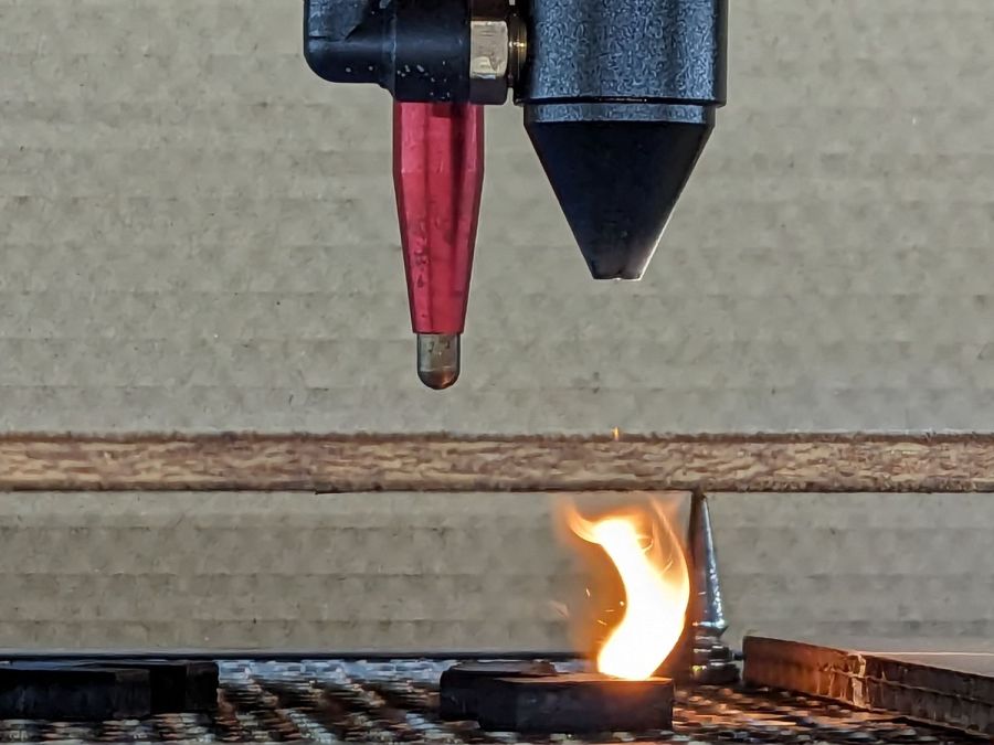
Moving the laser beam horizontally toward the center of Mirror 2 requires one or more of:
- Moving Mirror 2 farther away from the center of the cabinet, but it is already at that end of the X axis slots above
- Moving the laser tube toward the back of the cabinet, which also requires moving Mirror 1, which is almost at the end of its adjustment range.
- Moving Mirror 1 closer to the laser tube, which its adjustment slots do not permit
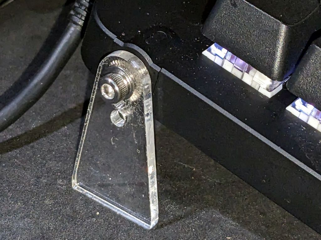
Mirror 1 sits on a pedestal with a slotted base allowing adjustments along the Y axis:
The pedestal could move a few millimeters to the rear, but the screw on the far side is even closer to its limit.
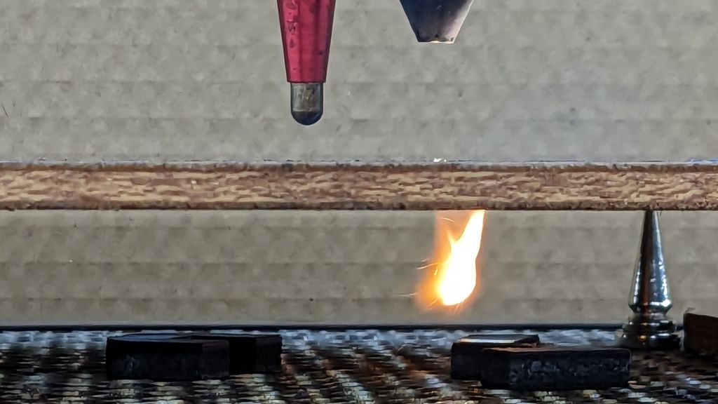
Moving the laser beam spot upward on the mirror requires:
- Lowering the mirror, which is obviously impossible given the position of the Z axis slots around the adjusting screws
- Raising the laser tube
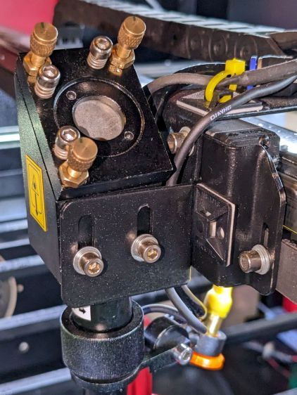
Mirror 3, inside the laser head on the gantry, was also sitting at the lowest possible point in its adjustment range:
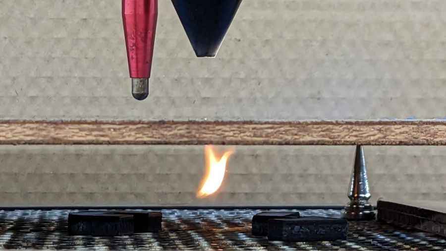
All of which suggested I should resign myself to adjusting the beamline:
- Raise the laser tube by 5 mm
- Move Mirror 1 closer to the laser tube by about 10 mm
Raising the tube gets both Mirror 2 and Mirror 3 off their Z axis adjustment limit, but requires raising Mirror 1.
Moving Mirror 1 gets Mirror 2 off its X axis adjustment limit.
Nothing changes the position of Mirror 2 on its Y axis screws, but that adjustment will help fine-tune the beamline into Mirror 3.
So I cut some 5 mm plywood spacers and nerved myself.


