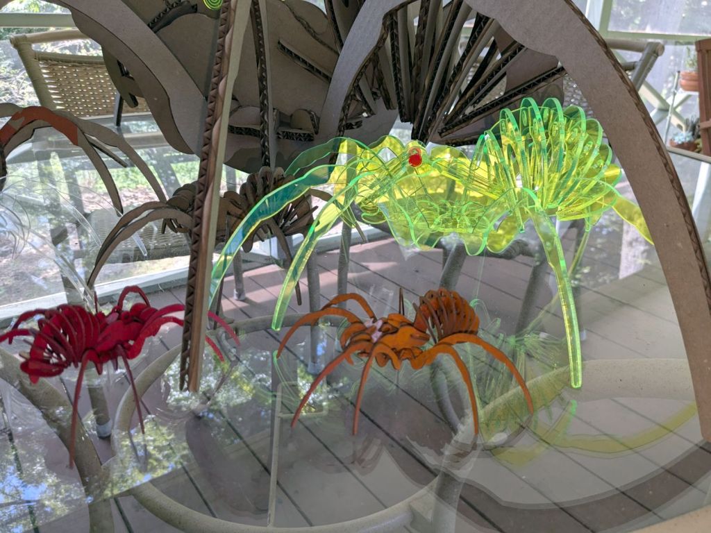
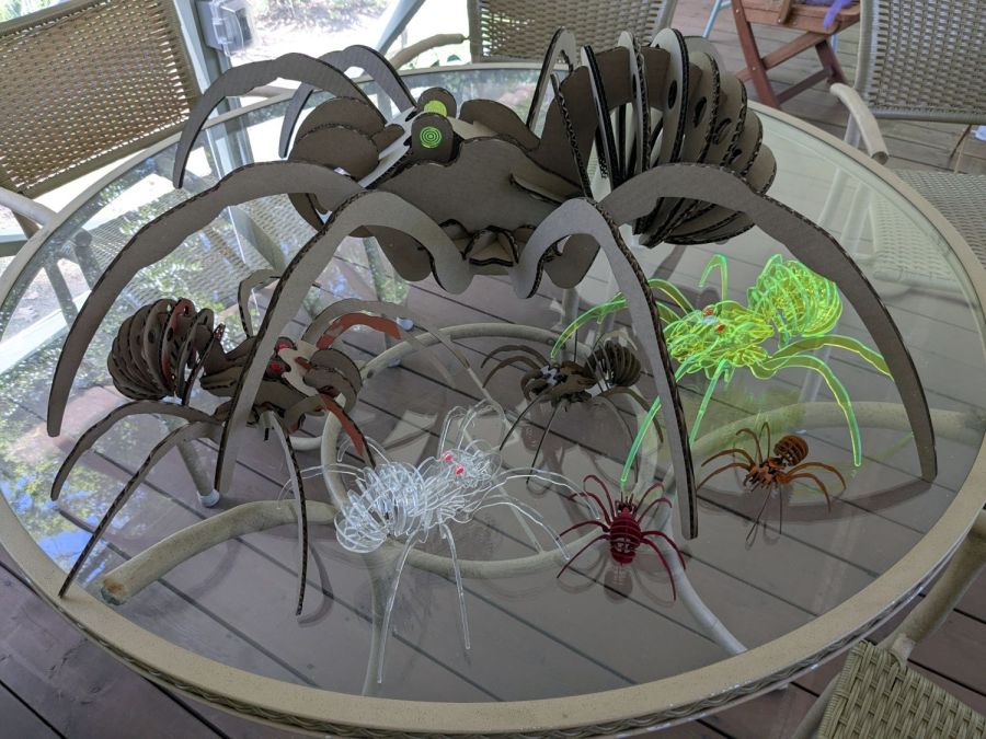
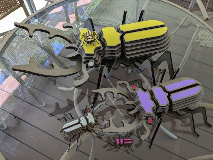
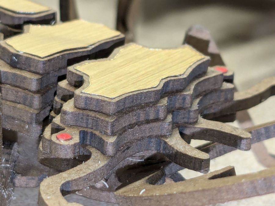
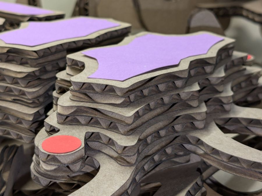
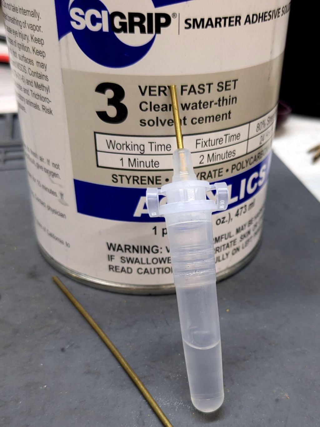
The Smell of Molten Projects in the Morning

Ed Nisley's Blog: Shop notes, electronics, firmware, machinery, 3D printing, laser cuttery, and curiosities. Contents: 100% human thinking, 0% AI slop.

Tag: Laser Cutter

  • LightBurn Slot Resizing

    LightBurn Slot Resizing

    LightBurn includes a Slot & Tab Resizer tool that automagically finds and resizes joints to adapt a design for whatever material thickness you might be using. To judge from the LightBurn forum threads, it doesn’t deal well with random designs fetched from the Interwebs, which suggests those designs were either never intended for laser cuttery or just badly laid out.

    So I fetched a sheep from a typical sketchy source and attempted to resize its slots:

    Sheep DXF import - slot resize problem
    Sheep DXF import – slot resize problem

    The tool looks for rectangular shapes within the Tolerance of the Old Material Thickness width, then marks their narrow ends with red highlights and their length with blue. Obviously, not all of the slots we humans see count as slots.

    A closer look at one of the body shapes with a slightly larger Tolerance shows some of the problems:

    Sheep DXF import - body
    Sheep DXF import – body

    Using the Node Editor tool reveals two stray nodes near the bottom of the second slot from the left:

    Sheep DXF import - slots
    Sheep DXF import – slots

    Zooming in and blowing out the contrast:

    Sheep DXF import - slot bottom
    Sheep DXF import – slot bottom

    Manually deleting those nodes doesn’t solve the problem, because two more errant nodes lurk at the top of the slot:

    Sheep DXF import - slot top
    Sheep DXF import – slot top

    You probably didn’t notice those at first glance, either. Those nodes may be very close together, but they still confuse the issue.

    Rather than tracking down and deleting / adjusting those nodes one by one, you can apply the Optimize Shapes tool to squash the superfluous nodes into straight lines:

    Sheep DXF import - optimized
    Sheep DXF import – optimized

    Don’t smooth the shapes or fit them to arcs at this point, because both of those operations will round off the corners.

    That may still leave a few nodes requiring manual intervention, as on the face shape:

    Sheep DXF import - optimized leftover
    Sheep DXF import – optimized leftover

    But at least the problem becomes tractable:

    Sheep and dinosaur flock
    Sheep and dinosaur flock

    As the Bard put it, all’s well that ends well.

  • Tyvek Engraving: FAIL

    Tyvek Engraving: FAIL

    Spurred by Jason’s comment on the laser test paper trials, I engraved some Tyvek:

    Tyvek engraving
    Tyvek engraving

    You probably can’t see the “Test!” engraved below the blue logo, as it just changed the texture of the envelope without producing a visible mark.

    The upper-right “Test!” ran at 10% (of 60 W) at 400 mm/s, with the others at 15% and 20%. The results suggest that it’s possible to remove ink and leave a visible mark, but it’s neither pretty nor dependable.

    Somebody’s gotta have a weather-stable, super-flexy, dual-color, laserable material, but so far it’s hidden below my horizon.

  • Laser Test Paper: Outdoor Testing

    Laser Test Paper: Outdoor Testing

    “Laser test paper” is, of course, intended for testing lasers, but I thought it might make a outdoor plant tag. A while ago I tried some Trolase Thins acrylic for that job:

    Plant tags - Trolase Thin - prototypes
    Plant tags – Trolase Thin – prototypes

    Which turned out to be entirely too stiff, which wasn’t surprising given that Trolase Thin is intended for signage stuck on flat or slightly curved surfaces.

    Despite being “paper”, laser testing paper is also too stiff:

    Laser test paper - outdoor labels - 2024-06-22
    Laser test paper – outdoor labels – 2024-06-22

    The wrinkles and cracks on the left end of the tags shows the plastic coating makes it basically impossible to shape / bend the paper enough to wrap around a plant stem, then push it through the hole (offscreen to the left). I was not surprised too much by this discovery.

    Those two strips now hang outside the kitchen window (left end upward), where they’ll get enough sun and rain to keep a plant happy, and I’ll see how well the engraved / damaged plastic coating stands up to that sort of abuse.

    For Science!

  • Laser-marked Hole Drilling Spots

    Laser-marked Hole Drilling Spots

    While setting up to drill holes in the aluminum base for the running light buck converter, I wondered if laser-marking the spots directly from the solid model would work better than my usual fumbling around.

    The solid model:

    Running Light - power box - bottom view
    Running Light – power box – bottom view

    Export projections of the pieces from OpenSCAD as an SVG file:

    Running Light - power box - Projection view
    Running Light – power box – Projection view

    Import into LightBurn, set up for a very fast, very light cut and Fire The Laser:

    Laser-marked hole spots - masking tape
    Laser-marked hole spots – masking tape

    That’s in ordinary masking tape on a hard-anodized sheet of aluminum from the pile, which looked better than I expected.

    The same aluminum covered with blue tape:

    Laser-marked hole spots - blue tape - hard anodize
    Laser-marked hole spots – blue tape – hard anodize

    Which looks much better in person than it does in the photo.

    On a soft aluminum sheet from the Basement Warehouse Zone:

    Laser-marked hole spots - blue tape - sheet aluminum
    Laser-marked hole spots – blue tape – sheet aluminum

    The dark outline is a comfort mark hand-drawn around a chipboard test piece to verify the layout fit between random holes drilled in the sheet during its previous life.

    A closer look at a corner hole:

    Laser-marked hole spots - blue tape - hard anodize - detail 1
    Laser-marked hole spots – blue tape – hard anodize – detail 1

    And the center hole:

    Laser-marked hole spots - blue tape - hard anodize - detail 2
    Laser-marked hole spots – blue tape – hard anodize – detail 2

    The holes appeared in the right places after center-punching by eye, but the fragility of those four little tape leaves around the center point must be experienced to be believed.

    And, yes, those are deliberately low-polygon approximations to a circle, because I’m a low-poly kind of guy.

    I really need an optical center punch if I do more such silliness. The box with those HP plotter digitizing sights recently came to hand, so I suppose I should make something.

  • Laser Test Paper

    Laser Test Paper

    A pack of Black Laser Engraving Testing Paper arrived and I put a few snippets to the test:

    Laser test paper - miniature pattern overview
    Laser test paper – miniature pattern overview

    That’s the standard backlash test pattern shrunken down to a little over an inch wide, with the laser power reduced to the bare minimum. Despite that, the numerous holes show where the pattern concentrates enough energy to vaporize the paper.

    The “paper” seems to be laminated between two black plastic sheets that smell terrible when engraved, so they’re probably some form of acrylic. The Amazon product description is, despite all the verbiage- remarkably uncommunicative of the actual materials involved.

    The circular pattern is 10 mm diameter on the outside:

    Laser test paper - miniature pattern detail
    Laser test paper – miniature pattern detail

    Those should be circles around the perimeter, but their distortion shows what happens when you try to move a hulking CO₂ laser head around a 1.5 mm diameter circle at 400 mm/s. Of course, the actual speed is nowhere near that fast along such tiny vectors.

    The traces are about 0.2 mm wide, with obvious scorches where the beam starts and stops, which agrees reasonably well with previous measurements.

    All in all, both the paper and the laser pattern look better than I expected, particularly as the results indicate the machine has no measurable backlash at all.

  • Laser-cut Profile Test Pieces

    Laser-cut Profile Test Pieces

    A new battery for my electrified Tour Easy recumbent arrived. It has newer 21700 lithium cells in the same overall box, but the baseplate requires new blocks adapting it to the frame:

    UPP Battery Mount - solid model
    UPP Battery Mount – solid model

    The top profile fits snugly into the battery mounting plate, with clearance on the sides for the latches:

    UPP Battery Mount - trial fit
    UPP Battery Mount – trial fit

    However, I had enough trouble measuring those recesses that I broke down and added a projection() view to the OpenSCAD code:

    UPP Battery Mount - profile
    UPP Battery Mount – profile

    Exporting that as an SVG image and importing it into LightBurn let me cut it out of chipboard:

    UPP Battery Mount - laser cut profiles
    UPP Battery Mount – laser cut profiles

    Obviously, it took several iterations to fit the top profile to the baseplate, particularly after finding slightly different measurements at each block position. On the other paw, laser cutting the profiles proceeded much more quickly than 3D printing just a few millimeters of the block, so it was a net win.

    The new battery baseplate doesn’t have an internal space for the buck converter feeding the running lights, so there’s more construction ahead.

  • Dish Drainer Drain Board Draining Improvement

    Dish Drainer Drain Board Draining Improvement

    It seems all the drain boards under dish drainers are now intended for contemporary under-counter sinks without a rim, which is not the Old School drop-in sink we have in the kitchen. After considerable faffing about, I hacked a fix to make the drain board & drainer fit the sink:

    Dish Drainer - sink lip cutout
    Dish Drainer – sink lip cutout

    The crude notch not only lowers the front edge by a few millimeters, it also encourages the lip to stay over the sink, rather than sliding back over the counter and slobbering water everywhere.

    The drain board has stiffening ribs under the center section, cleverly arranged so they do not actually touch the counter. I measured the shape of the board near the ribs:

    Dish Drainer - measuring center ribs
    Dish Drainer – measuring center ribs

    And then cut shapes to both support the board and rest on the counter:

    Dish Drainer - center support
    Dish Drainer – center support

    The board has a swale in the middle, directly over those ribs, requiring more tilt for proper drainage:

    Dish Drainer - rear support
    Dish Drainer – rear support

    Getting all of that flying in formation required several iterations and we’re still not entirely satisfied, but at least the water flows into the sink and does not puddle in the drain board or on the counter.

    Stipulated: wood is the wrong material for the job, hot melt glue is breathtakingly ugly, and you want no part of this.

    You can buy fancier drain boards, some with cute spouts leading into the sink, but the fine print suggests most expect to work with rimless under-counter sinks.