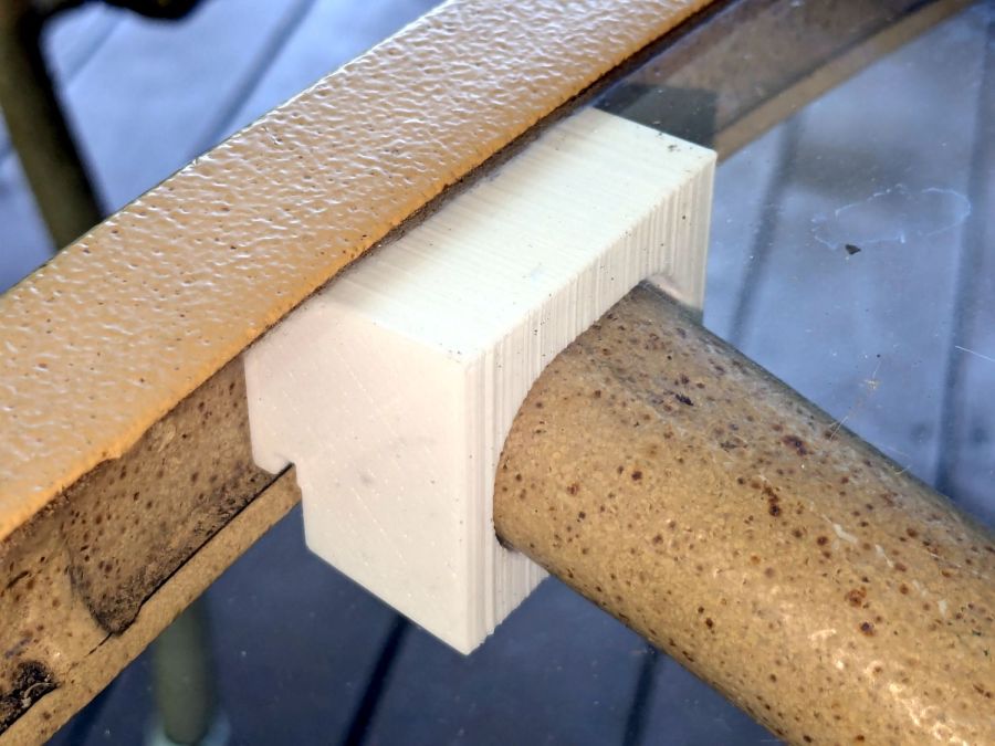
A glass-top patio table came with our house and, similar to one of the patio chairs, required some repair. The arched steel legs fit into plastic brackets / sockets around the steel table rim under the glass top:

The four glaringly obvious white blocks are the new brackets.
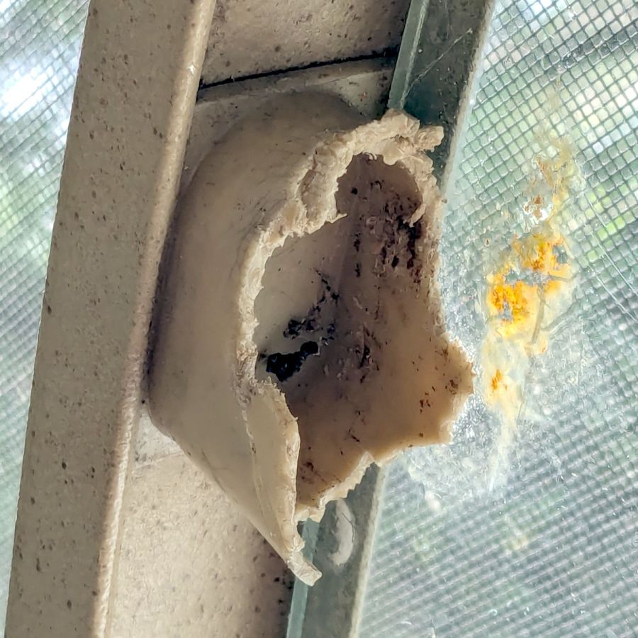
The original brackets had, over uncounted years, deteriorated:

Perhaps disintegrated would be a better description:
Each leg has a pair of rusted 1-½ inch ¼-20 screws holding it to the central ring. As expected, seven of the eight screws came out easily enough, with the last one requiring an overnight soak in Kroil penetrating oil plus percussive persuasion:

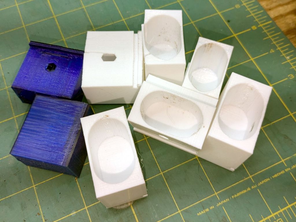
The four legs had three different screws holding them to the brackets, so I drilled out the holes and squished M5 rivnuts in place:

Although it’s not obvious, the end of that tube is beveled with respect to the centerline to put both the top and bottom edges on the table rim inside the bracket. In addition, the tube angles about 10° downward from horizontal, which I did not realize amid the wrecked fittings, so the first bracket model failed instantly as I inserted the leg:

The top & bottom walls of that poor thing were breathtakingly thin (to match the original bracket) and cracked when confronted with the angled tube. I could not measure all the sizes & angles without assembling the table on trial brackets, so getting it right required considerable rapid prototyping:

Some trigonometry produced a solid model with features rebuilding themselves around the various sizes / angles / offsets:

A sectioned view shows the angled tube position and end chamfer:

The OpenSCAD code can produce a sectioned midline slice useful for laser-cut MDF pieces to check the angle:

That eliminated several bad ideas & misconceptions, although trying to balance the leg on a 3 mm MDF snippet was trickier than I expected. In retrospect, gluing a few snippets together would be easier and still faster than trying to print a similar section from the model.
The slightly elongated slot for the M5 screw shows that the original screw holes were not precisely placed or that the tubes were not precisely cut, neither of which come as a surprise. I finally built some slop into the design to eliminate the need for four different blocks keyed to four different legs.
The outer rim, the notch on the bottom, and the tab on the top curve to match the four foot OD glass tabletop, with the inward side & ends remaining flat:
The sector’s difference from a straight line amounts to half a millimeter and improved the fit enough to justify the geometric exercise. The bracket snaps into position with the notch over the table rim and the tab locked in the gap between the glass disk & the rim, although I suspect the weight of the tabletop would keep everything aligned anyway.
The walls are now at least 4 mm thick and, printed in PETG, came out strong enough to survive assembly and some gentle testing. They’re arranged to print on their side to eliminate support under those slight curves and to align the layers for best strength vertically in the finished bracket:
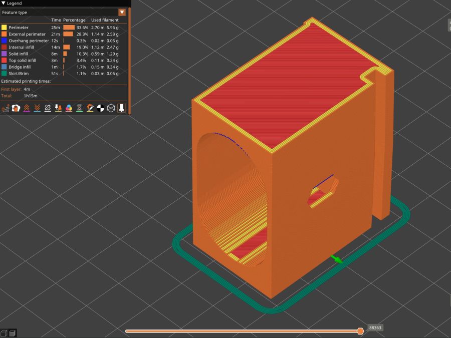
The leg cavity and screw hole built well enough without internal support.
They’re relentlessly rectangular and I’m not going to apologize one little bit.
Now to see how they survive out there on the screened porch.
The OpenSCAD source code as a GitHub Gist:
| // Glass patio table leg brackets | |
| // Ed Nisley – KE4ZNU | |
| // 2024-08 | |
| /* [Layout] */ | |
| Layout = "Show"; // [Section,Projection,Show,Build] | |
| Part = "Leg"; // [Leg, RimPlate, Block, Bracket] | |
| /* [Hidden] */ | |
| ThreadWidth = 0.40; | |
| ThreadThick = 0.25; | |
| HoleWindage = 0.2; | |
| Protrusion = 0.1; | |
| //—– | |
| // Dimensions | |
| /* [Hidden] */ | |
| GlassOD = 1230.0; // inner edge of upper tab | |
| GlassThick = 5.0; | |
| WallThick = 4.0; | |
| TOP = 0; | |
| BOT = 1; | |
| TabWidth = [3.0,3.0]; // locking tabs, top & bottom | |
| TabHeight = [0.5,3.0]; // … height | |
| LegOA = [16.0,36.5,23.0]; // X insertion, Y around glass, Z upward | |
| LegAngle = 10; | |
| ScrewOffset = [8.0,10.0]; // from socket bottom | |
| ScrewOD = 6.0; // clearance hole | |
| Plate = [1.0 + 2*max(TabWidth[TOP],TabWidth[BOT]), | |
| LegOA.y + 2*WallThick, | |
| 25.5 | |
| ]; | |
| echo(Plate=Plate); | |
| BlockOA = [LegOA.x*cos(LegAngle) + (LegOA.z/2)*sin(LegAngle) + WallThick, | |
| Plate.y, | |
| LegOA.z/cos(LegAngle) + 2*LegOA.x*sin(LegAngle) + 2*WallThick | |
| ]; | |
| echo(BlockOA=BlockOA); | |
| //—– | |
| // Useful routines | |
| function IntegerMultiple(Size,Unit) = Unit * ceil(Size / Unit); | |
| module PolyCyl(Dia,Height,ForceSides=0) { // based on nophead's polyholes | |
| Sides = (ForceSides != 0) ? ForceSides : (ceil(Dia) + 2); | |
| FixDia = Dia / cos(180/Sides); | |
| cylinder(r=(FixDia + HoleWindage)/2, | |
| h=Height, | |
| $fn=Sides); | |
| } | |
| //—– | |
| // Table Leg | |
| // Including screw slot | |
| // Additional length to allow use as difference | |
| module Leg() { | |
| union() { | |
| difference() { | |
| rotate([0,90,0]) | |
| translate([0,0,-LegOA.x]) | |
| linear_extrude(height=4*LegOA.x,convexity=5) | |
| hull() | |
| for (j=[-1,1]) | |
| translate([0,j*(LegOA.y – LegOA.z)/2]) | |
| circle(d=LegOA.z); | |
| rotate([0,-LegAngle,0]) | |
| translate([-2*LegOA.x,0,0]) | |
| cube(4*LegOA,center=true); | |
| } | |
| hull() | |
| for (c = ScrewOffset) | |
| translate([each c + (LegOA.z/2)*sin(LegAngle),0,-LegOA.z]) | |
| //rotate(180/6) | |
| PolyCyl(ScrewOD,LegOA.z,6); | |
| } | |
| } | |
| // Rim Plate | |
| module RimPlate() { | |
| n = 16*4*3; | |
| render(convexity=5) | |
| translate([-Plate.x,0,0]) | |
| difference() { | |
| intersection() { // shape outer side to match table rim curve | |
| translate([0,-Plate.y/2,0]) | |
| cube(Plate,center=false); | |
| translate([GlassOD/2 + TabWidth[TOP],0,0]) | |
| cylinder(d=GlassOD + 2*TabWidth[TOP],h=Plate.z,center=false,$fn=n); | |
| } | |
| translate([GlassOD/2 + TabWidth[TOP],0,Plate.z – TabHeight[TOP]]) | |
| cylinder(d=GlassOD,h=Plate.z,center=false,$fn=n); | |
| translate([GlassOD/2 + TabWidth[BOT],0,-(Plate.z – TabHeight[BOT])]) | |
| difference() { | |
| cylinder(d=GlassOD,h=Plate.z,center=false,$fn=n); | |
| cylinder(d=GlassOD – 2*TabWidth[BOT],h=Plate.z,center=false,$fn=n); | |
| } | |
| } | |
| } | |
| // Block surrounding leg | |
| module Block() { | |
| intersection() { | |
| translate([BlockOA.x/2,0,0]) | |
| cube(BlockOA,center=true); | |
| translate([0,0,BlockOA.x*sin(LegAngle) – BlockOA.z/2]) | |
| rotate([0,LegAngle,0]) | |
| translate([-2*BlockOA.x,-2*BlockOA.y,0]) | |
| cube(4*BlockOA,center=false); | |
| } | |
| } | |
| // Complete bracket | |
| module Bracket() { | |
| difference() { | |
| union() { | |
| RimPlate(); | |
| translate([0,0,Plate.z – BlockOA.z/2 – TabHeight[TOP] – 0*WallThick]) | |
| Block(); | |
| } | |
| translate([0,0,1*Plate.z/2 – 1*WallThick]) | |
| rotate([0,LegAngle,0]) | |
| translate([WallThick,0,0]) | |
| Leg(); | |
| } | |
| } | |
| //—– | |
| // Build things | |
| // Layouts for design & tweaking | |
| if (Layout == "Section") | |
| intersection() { | |
| Bracket(); | |
| translate([0,BlockOA.y/2,0]) | |
| cube([4*BlockOA.x,BlockOA.y,3*BlockOA.z],center=true); | |
| } | |
| if (Layout == "Projection") | |
| for (j = [1]) | |
| translate([0,j*2*BlockOA.z]) | |
| projection(cut=true) | |
| translate([0,0,j*5.0]) | |
| rotate([90,0,0]) | |
| Bracket(); | |
| if (Layout == "Show") | |
| if (Part == "Leg") | |
| Leg(); | |
| else if (Part == "RimPlate") | |
| RimPlate(); | |
| else if (Part == "Bracket") | |
| Bracket(); | |
| else if (Part == "Block") | |
| Block(); | |
| // Build layouts for top-level parts | |
| if (Layout == "Build") { | |
| translate([0,0,Plate.y/2]) | |
| rotate([90,0,0]) | |
| Bracket(); | |
| } | |
Some dimension doodles, not all of which correspond to reality:

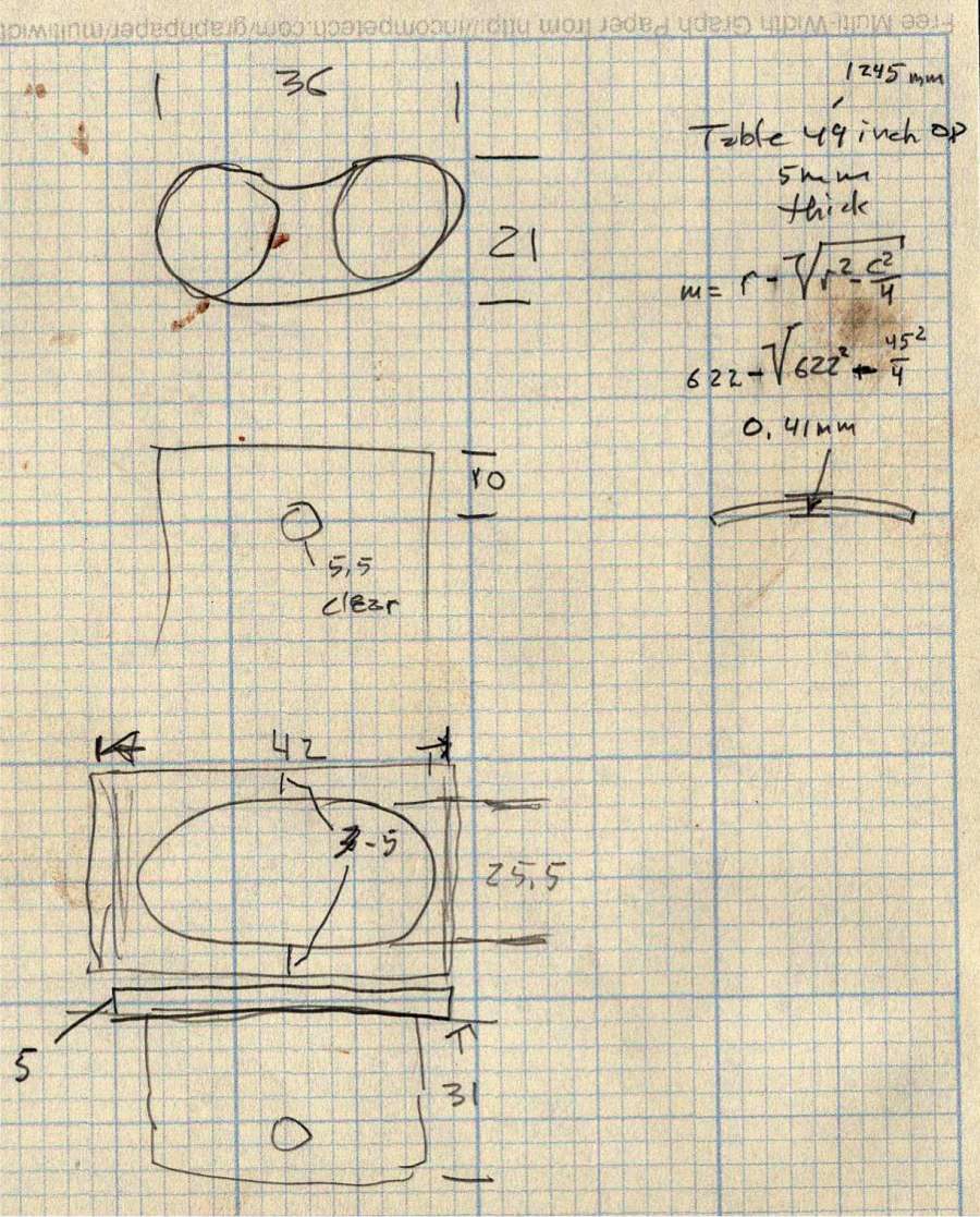
See? It’s not all slotted animals all the time around here …