Ed Nisley's Blog: Shop notes, electronics, firmware, machinery, 3D printing, laser cuttery, and curiosities. Contents: 100% human thinking, 0% AI slop.
I want to put the HLP-200B Laser Power Meter at the tube’s exit, just upstream from Mirror 1, where it can measure the laser’s power output before the mirrors get into the act. Reaching the Pulse button on the machine console requires much longer arms than any normal human can deploy, plus a certain willingness to lean directly over a laser tube humming with 15 kV at one end.
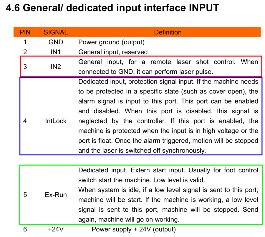
Perusing the KT332N doc brings up a hint, blocked in red so you can make some sense of it:
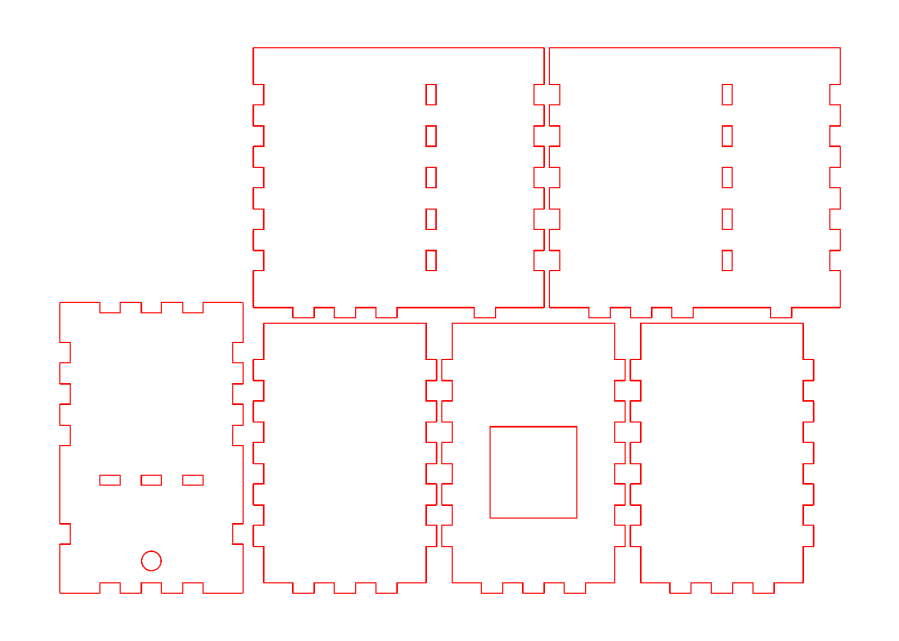
Another few minutes produces the box from Trocraft Eco, which is not quite thin enough for the switch (from my Box o’ Clicky Buttons) to snap into place, but a few dabs of hot melt glue hold it down:
Laser remote pulse button – installed
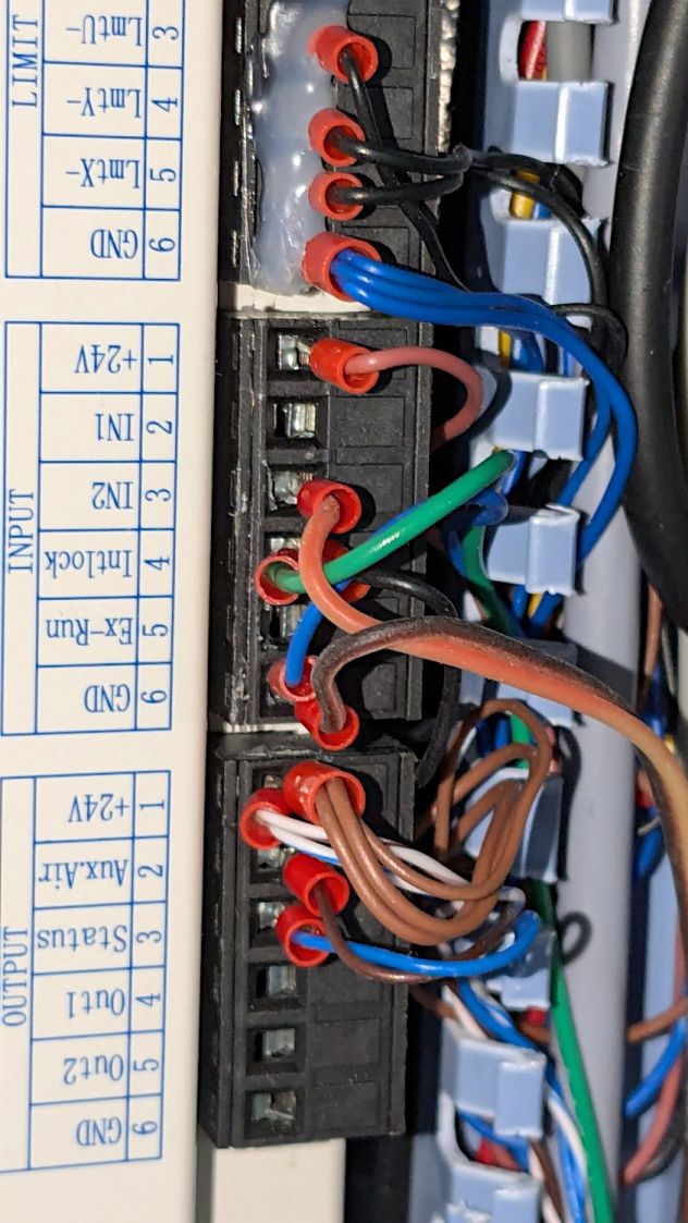
Double-sided foam tape sticks the box to the laser frame and the red-n-black cable snakes all the way across the back of the machine and through the electronics bay to the IN2 and GND terminals of the KT332N INPUT block:
Laser remote pulse button – Ruida KT332N wiring
With the laser head parked at a safe spot and all interlocks happy, it works:
Laser remote pulse button – demo
That is a re-enactment, because I lack sufficient dexterity to handle a phone with my left hand, poke the button with my right finger, and not damage anything important.
The general idea is to make it very difficult to inadvertently press that button: you must want to fire the laser with the tube compartment hatch up (it has no interlocks) and the control panel out of sight on the top-front of the machine.
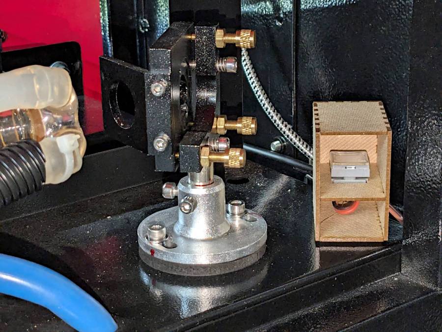
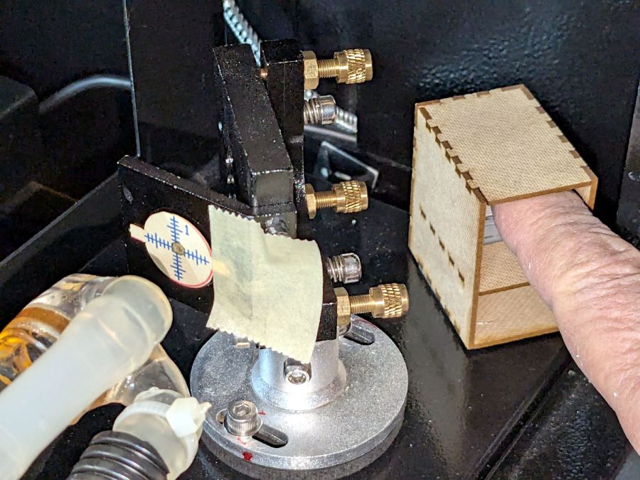
Setting the power to 30% and putting the meter in harm’s way:
HLP-200B – Laser tube exit
Again, a reenactment based on actual events.
Five pulses later:
40.8
W
42.4
42.3
41.2
40.7
41.5
W avg
0.82
W std dev
For the record, those five pulses dumped about 5 × 42 W × 10 x ≅ 2000 W·s = 2 kJ into the meter, raising it from “chilly basement ambient” to “be careful where you hold it”, thus making the meter’s aluminum case the least-efficient handwarmer in existence.
The large standard deviations prevent firm conclusions, but, yeah, the power at the tube exit seems about right, before two mirrors and ≅800 mm of path length take their toll.
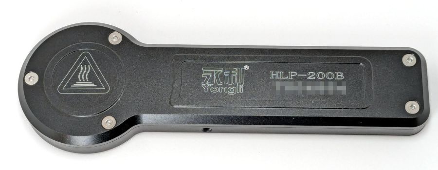
The HLP-200B Laser Power Meter Handheld comes fully calibrated at 10.6 μm (CO2). Each laser power meter we calibrate is directly traceable to NIST absolute standards because we use GOLD standards as a reference for each calibration. You will obtain the most accurate result possible
A line in the description says “+/- 3% within the central section”, but that’s not much help. Back in the day, any error percentage referred to the meter’s full-scale value, which would be ±6 W for a 200 W meter.
So I plunked the meter in the middle of the laser platform:
HLP-200B Laser Power Meter – platform center
Then took five measurements at each of ten power levels:
PWM %
10
20
30
40
50
60
70
80
90
99
°C
17.2
17.9
18.4
19.0
19.4
20.3
20.0
20.0
20.5
19.4
Tube Current
3
4
7
10
14
16
18
20
22
24
W
7.1
21.0
42.0
51.8
59.1
63.0
67.8
69.6
74.7
64.0
6.0
19.8
37.2
48.9
52.7
56.0
65.1
69.6
72.4
71.8
6.4
21.1
39.3
45.6
56.5
53.2
61.1
60.7
74.6
75.2
5.6
17.8
37.1
40.4
55.3
53.2
55.1
64.2
74.9
73.5
6.0
17.7
36.9
45.1
54.5
53.1
62.2
69.9
72.2
70.9
Avg Power
6.2
19.5
38.5
46.4
55.6
55.7
62.3
66.8
73.8
71.1
std dev
0.57
1.66
2.19
4.29
2.39
4.26
4.78
4.16
1.34
4.29
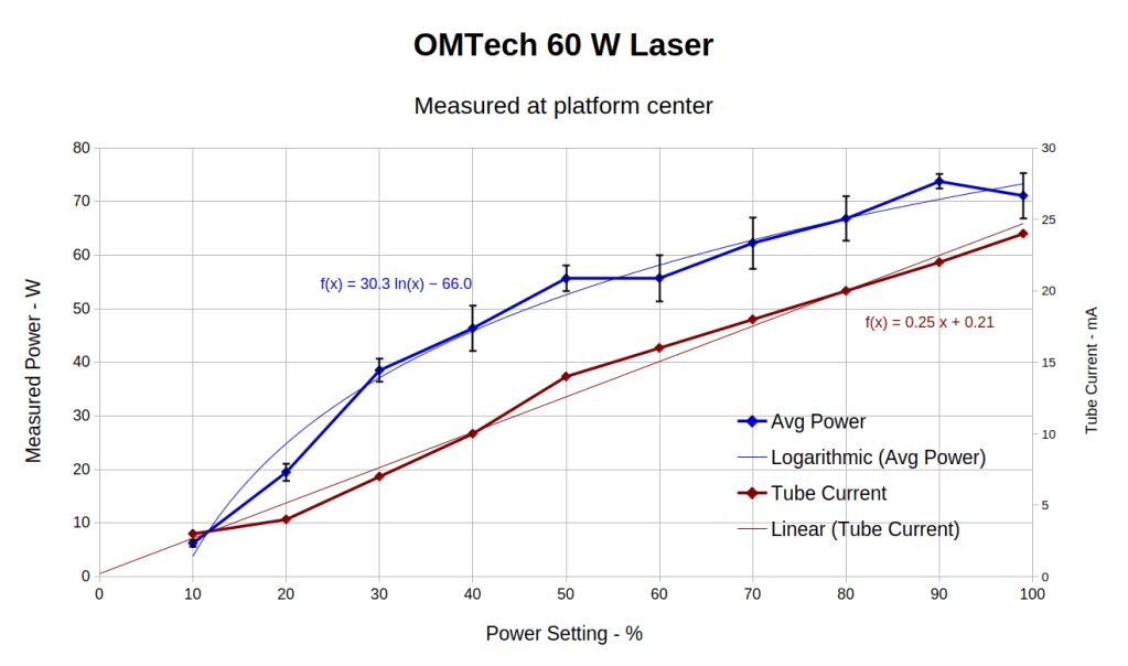
That’s easier to digest from a graph:
HLP-200B Laser Power Meter – 60 W platform center measurements
The absurdity of computing the sample standard deviation from five measurements taken at each power level does not escape me, but this just surveys the situation.
Earlier measurements of the tube current vs. PWM setting, using an RMS value computed by the oscilloscope’s firmware, produced a plot resembling the brown points (read the mA scale on the right) at the high end and differing greatly on the low end. These values come from the power supply’s digital meter, but the straight-line fit doesn’t look absurdly forced and the zero intercept seems plausible. I *assume* it’s actually measuring the tube current, rather than displaying a value computed from the PWM input, but I don’t know for sure.
The rather sketchy paperwork accompanying the laser had one handwritten “21 mA” seemingly corresponding to 60 W output, which looks approximately correct. The instruction manual has a table of power vs. current suggesting that 65-ish W corresponds to 18 mA, with 100 W at 23 mA; it’s unclear whether that is for the 60 W tube in the machine or applies to the entire range of available tubes. The manual recommends not using more than 95% PWM, with which I heartily agree.
Because my meter stand holds the target in the same position relative to the beam during successive measurements much better than I could by hand, I think the pulse-to-pulse variation comes from meter and tube repeatability.
Earlier measurements with a grossly abused Gentec ED-200 joulemeter suggested the laser has some pulse-to-pulse timing variation, down in the millisecond range, but produced roughly the right power for middle-of-the-range PWM settings. This meter integrates the beam power over about ten seconds, so I think variations will be due to (possible) tube power changes and meter repeatability, rather than timing errors.
Obviously, you must not depend on any single-shot measurement to fall within maybe 10% or several watts of the right answer.
With all that in mind and assuming the meter is delivering approximately the right numbers on average, the power supply overcooks the tube at any PWM setting above 50%. I’ve noticed some beam instability / defocusing over 80% while cutting recalcitrant materials, which is surely due to the tube not lasing properly. I generally avoid doing that.
The log fit to the measured power looks better than I expected, although I’m unprepared to compute natural logs in my head.
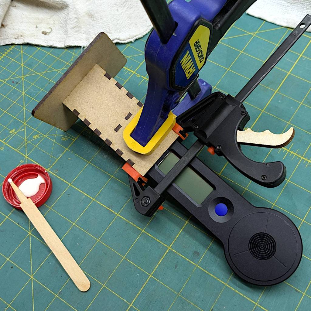
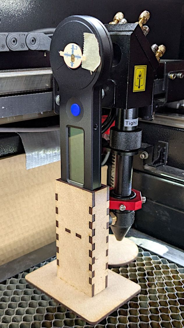
The overall measurement process for the HLP-200B laser power meter requires more coordination than I can muster on a dependable basis, so a third hand seemed in order:
HLP-200B Power Meter – target setup
In actual use, a pair of finger-crushingly strong magnets laid on the base hold it firmly to the honeycomb.
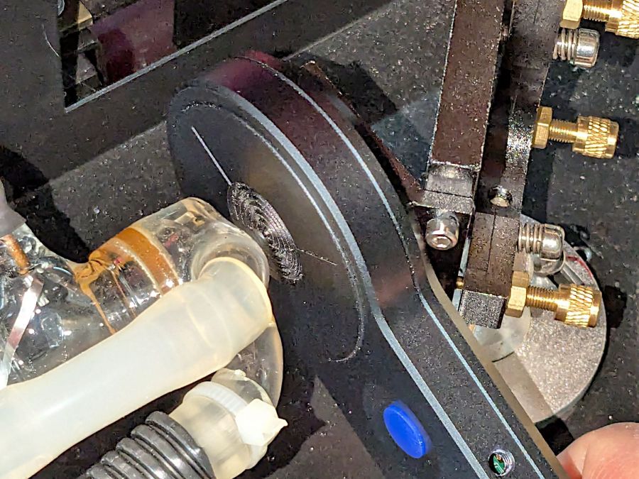
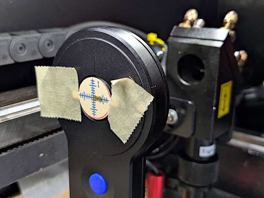
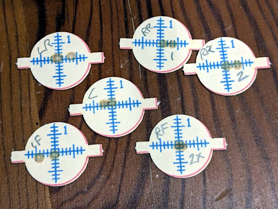
Because a CO₂ laser beam is invisible, the only way to know where it hits is to char a bit of paper:
HLP-200B Power Meter – target detail
With that evidence, I can jog the platform up-and-down and the gantry front-and-back to center the beam on the paper target and, thus, on the sensor behind it. That process happens at each test position across the platform:
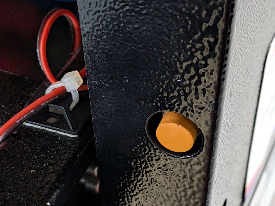
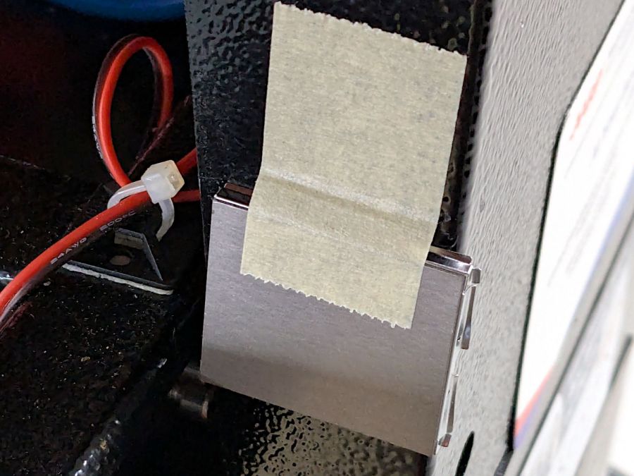
Rather than install a switch to bypass the interlock, I taped a steel cover harvested from defunct electronics over the sensor:
Laser lid interlock sensor – bypassed
Which has the useful side effect of preventing me from closing the lid with the interlock defeated.
The holder is just slightly larger than the meter’s handle and some clamps produced a snug fit while the glue cured:
HLP-200B Power Meter – holder gluing
The holder keeps the meter sensor at the same position vertically and within about a millimeter horizontally. The laser beam seems to be around 5 mm in diameter (the scorches above come from the hottest central part), so the beam should hit the same position on the sensor during successive measurements, making them far more repeatable than my waving it around by hand.
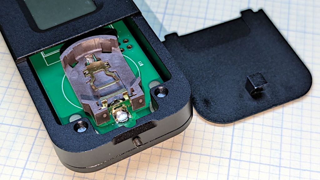
The manual does not exactly match the hardware. In particular, “so users won’t need any tools to replace the battery” is incorrect:
HLP-200B – battery lid screw
Until you loosen the M2 setscrew below the finger notch a couple of turns, “Use just fingers to remove the battery cover” will merely scuff your fingerprints. Apply a 1.5 mm or 1/16 inch straight screwdriver bit with no more than finger torque and, after two or three turns, the lid comes free.
The meter arrives without a battery, so you passed the first test.
Despite the “another screw hold (M4) is added”, there’s only one tapped hole in the case, as visible in the back panel photo. Seen from the front, it’s above the four digit LCD.
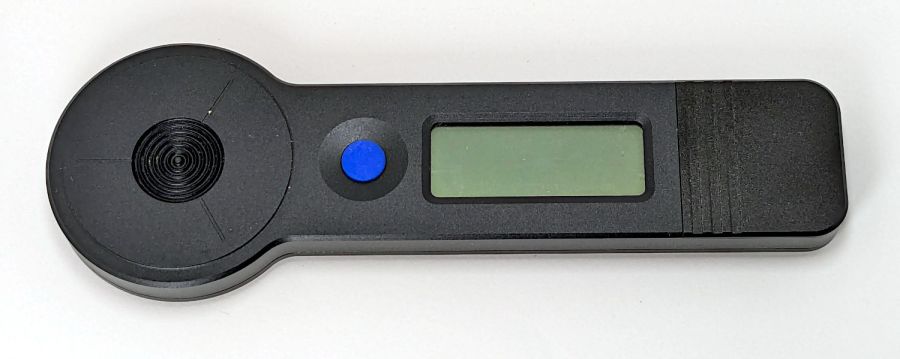
Operation is at best awkward and at worst hazardous:
Press the blue button to turn it on and hear a beep
It’s ready to measure within three seconds
Hit it with the laser beam until it beeps
The LCD shows the power for six seconds
It shuts off with a beep
Bonus: If the meter doesn’t detect any energy, it shuts off 20-ish seconds after the button press
Minus my power ears, the beeps are completely inaudible.
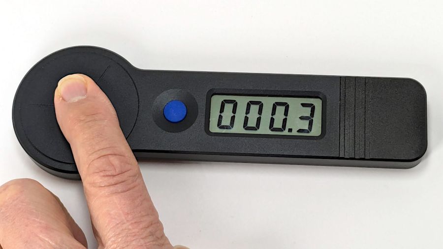
The meter is sensitive enough to respond to weak heat sources like LED bulbs and even fingertips, so you can test it without firing the laser. The numeric value shows the power from a CO₂ laser beam dumping an equivalent amount of energy into the sensor:
HLP-200B – finger heat response
The sensor target is 20 mm OD, although the instructions remind you to “Ensure the laser is emitted to the center of the sensor”. I suspect hitting the sensor with a focused laser spot will eventually damage the surface.
Making a real measurement requires:
Set the Pulse button for continuous output
Set the power level
Defeat the lid interlock switch on the laser cabinet
Push the blue button on the HLP-200B
Quickly position the meter target accurately in the beam path
Hold down the laser Pulse button
Freeze in that position until the meter beeps
Release the Pulse button
Quickly reorient the meter and read the display
I have a visceral reluctance concerning safety interlock overrides, misgivings about poking my head inside the cabinet, and no yearning to put one hand near the beam line with the other on the console. Yes, I have known-good laser safety glasses.
The meter generates plausible results for the (claimed) 60 W tube in my machine, but further tests await conjuring fixtures to keep various irreplaceable body parts out of harm’s way.
I wanted to work with that desktop from my Comfy Chair upstairs, because I’m unwilling to stand up a Windows box specifically for another LightBurn installation, along with a nightmare KVM switch tangle for all the displays / keyboards / trackballs I run with Linux.
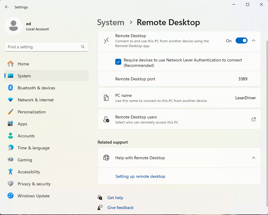
At the Win 11 PC, turn on Remote Desktop connections:
Remote Desktop enable
The Administrator is automatically allowed access, but I also allowed access for my local User (who does not have a Microsoft account), which requires the Administrator’s password. You’ll want to store that in a password manager, because typing line noise gets tedious.
Upstairs on the Comfy Chair at the Linux box, install Remmina from the repository, then tweak some preferences:
Remmina prefs – General
This being a LAN connection, pick the highest quality scaling, although that shouldn’t matter with a fullscreen display. I added a screen resolution matching my desktop landscape monitor:
Remmina config – screen resolutions
Somewhat to my surprise, selecting an RDP screen resolution larger than the HDMI monitor on the Win 11 box worked perfectly.
Because the remote display will fill the entire screen in fullscreen mode, set the toolbar to “Peeking” mode making it barely visible at the top of the screen:
Remmina prefs – Appearance
I have yet to (figure out how to) enable the hotkey turning fullscreen mode on and off, so if the toolbar isn’t readily available there is no way to get out of fullscreen mode.
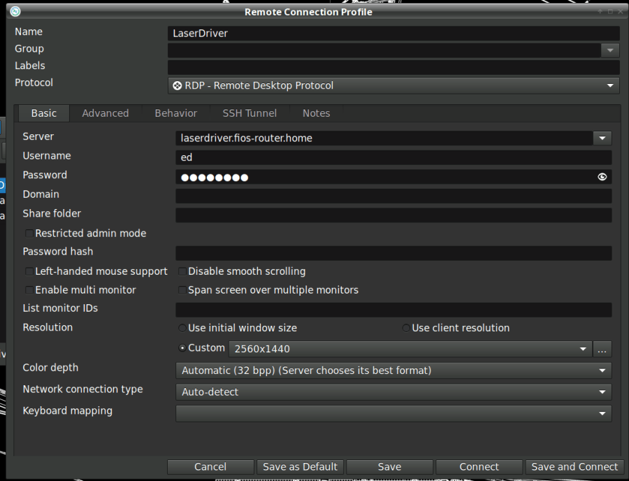
Set up the RDP connection to the Win 11 box, using either the static IP address or whatever name the router assigns:
Remmina config – Basic
I set the Win 11 box for a static IP address, then told the router to assign that IP to the box if it ever woke up asking for an address through a DHCP request. The process differs depending on which router you have and may not be needed. I (try to) nail down all the IP addresses, so anything using DHCP will be obviously in need of attention.
Select the highest quality compression:
Remmina config – Advanced
With all that set up, double-clicking the appropriate line should fire up an RDP connection, perhaps with a peephole view of the Win 11 desktop:
Remmina – small RDP window
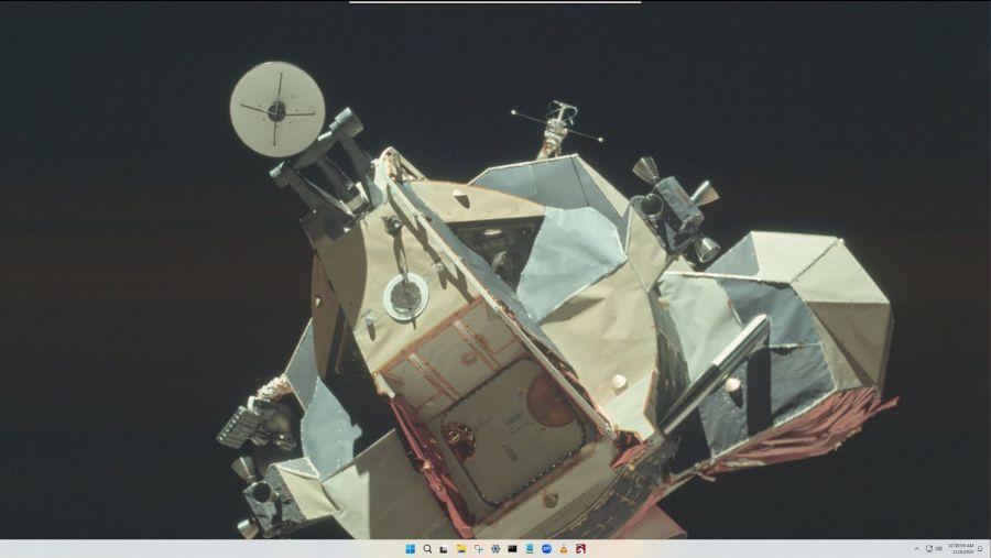
Hit the Toggle Fullscreen icon (hollow square, fifth down) to embiggen it:
The thin line along the center top is the Remmina toolbar, peeking over the edge. Move the mouse cursor up there to roll it down into view:
Remmina – fullscreen RDP window – detail
Because this is a fullscreen view, hitting the Toggle Fullscreen icon (highlighted blue) is the only way out. It required a disturbing number of iterations before realizing none of the hotkeys worked, then figuring out how to enable toolbar peeking.
Moving the mouse pointer to the bottom of the screen rolls up the Win 11 Task Bar (which I always set to Hide mode to get it out of the way):
Remmina – fullscreen – task bar
I pinned the LightBurn icon to the task bar where it’s easy to hit, as that’s the whole point of the exercise.
And then It Just Works™:
Remmina – fullscreen LightBurn
Because this is Windows, one user can sign onto the box from either the local keyboard or the RDP connection, but not both.
Being an Old School type of guy, I reflexively save my work before trotting either upstairs or downstairs and signing on wherever I end up, but it’s the same file in the same program on the same hardware.
The performance over the LAN and through Remmina is good enough to make the fullscreen session feels exactly like running LightBurn locally. In truth, LightBurn is not a particularly resource-heavy program.
Then I deleted both Linux installations from the LightBurn license portal …
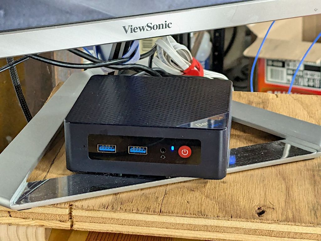
It’s a BeeLink Mini S12 (whatever that means) and squats near the low end of PC performance these days. I chose it based on reports from folks at Squidwrench having used similar units for various purposes without much pain, plus motivation from one of those weird Amazon “coupons” knocking the price down; it now sells for about that same price without the coupon.
It’s advertised as coming with Windows 11, but my advisors recommended a clean installation to get rid of crapware and possible pre-installed malware. I decided to start with the as-delivered system, then use the same product key to blow away the default installation.
The box / packaging did not include a Microsoft Windows Product Key and going through the first boot setup process produced this disconcerting result:
Win 11 license key – not found
More disconcerting: Windows Defender (Microsoft’s antivirus scanner / system integrity checker) was inactive and could not be installed from the MS “Store”. While not conclusive proof of pre-installed malware, the situation certainly seemed suspicious.
The seller sent a key that seemed to be for Windows 10:
BeeLink MS Product Key – Win 10 – redacted
Having been assured this would also validate a Win 11 installation, I did a clean installation using a USB flash drive produced by the MS installer, was never asked for a key, and eventually got to this point:
Win 11 Pro Installed Key – requires Digital License – redacted
Despite the missing OEM key and the footnote, everything seems just ducky:
Win 11 Activation with Digital License
I assume a clean installation blows away any malware resident on the “hard drive” (an M.2 solid state drive, of course), including rootkits and boot sector malware. My threat model does not include malware in the BIOS / UEFI firmware, which may be overoptimistic.
I declined all the optional MS products, refused various MS subscriptions, and generally tried to kill off a myriad invasive / advertising / “customized for you” features along the way. A casual search will produce many helpful guides for that process; I expect the details will change as MS continues to extract information from us. I set up a non-Administrator account for myself specifically to run LightBurn.
With that accomplished, I gave it a static IP address, created network shares to various directories on the “file server” (an ancient off-lease Dell Optiplex) holding the files I previously used with Linux LightBurn, installed Window LightBurn, got its preferences sorted out / restored from backup, and things eventually worked pretty much as intended.
This setup is intended for layout tweaking and laser control, not for protracted design work while standing in what’s now a 57 °F = 14 °C basement.
For what it’s worth, I must run the laser’s water chiller for half an hour to raise the cooling water to the normal 20 °C operating range; it has a water-cooled pump serving as a little heater.
The next step involved enabling Remote Desktop Protocol access so I can access the Windows box from my Comfy Chair at my usual battle station upstairs. More on that tomorrow …


