Mary’s Juki TL-2010Q sewing machine sits in an Arrow Gidget II sewing table with a clear acrylic insert filling the opening:
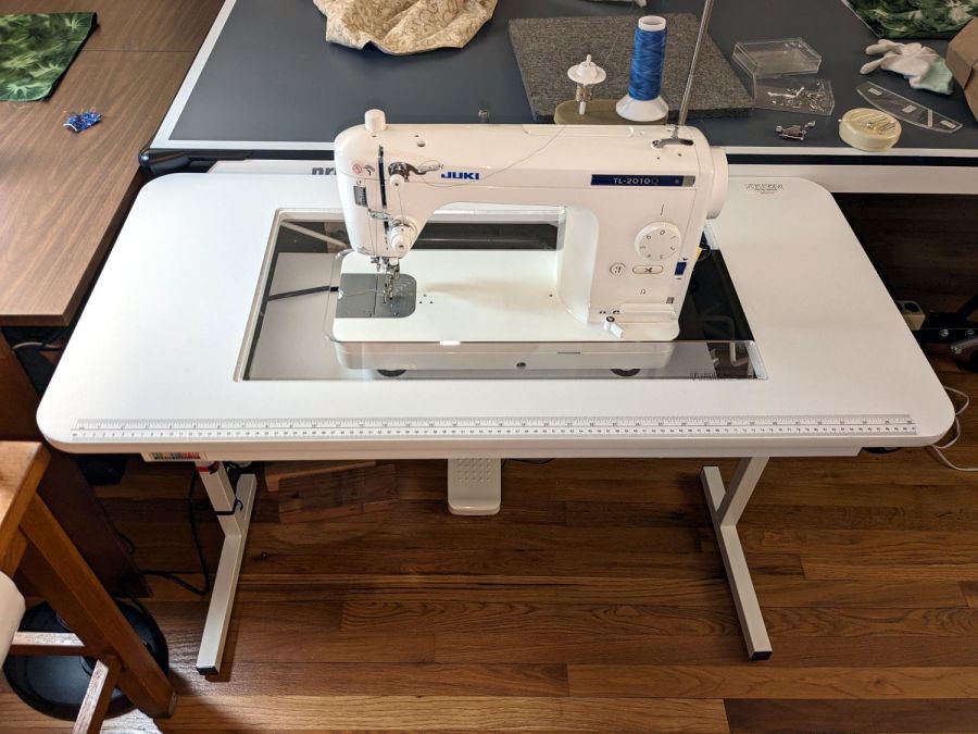
Before the insert arrived (it had month of leadtime), I hacked out a temporary cardboard insert:
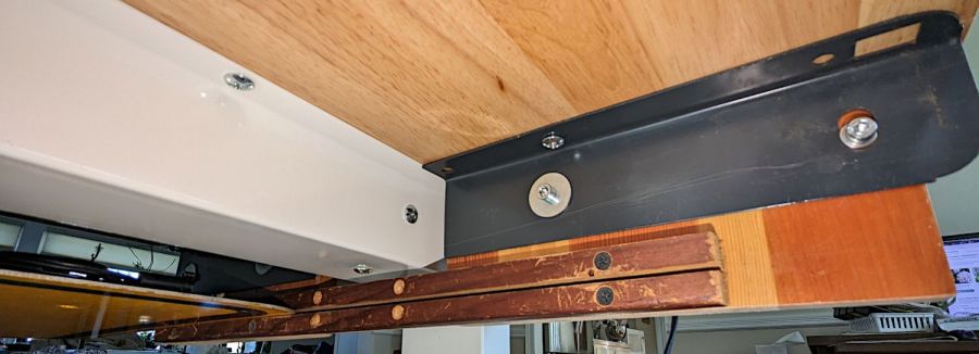
Although it may not be obvious from the picture, unlike my cardboard insert, the acrylic insert does not fill the tabletop hole to the immediate right of the machine:
Custom Inserts are U-shaped, designed to fit around all 3 sides of your sewing machine
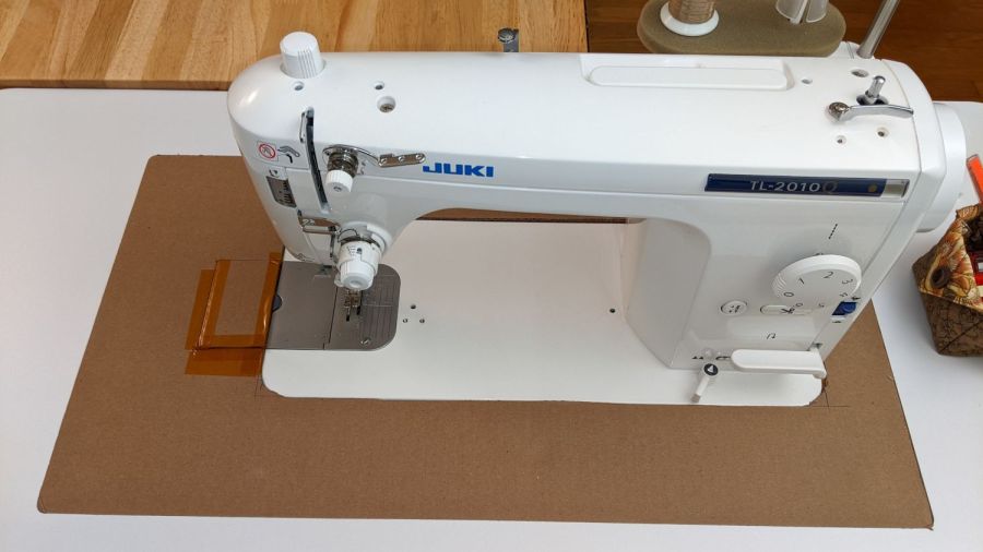
Shortly after the insert arrived I hacked a temporary filler, for which no pictures survive, to keep pins / tools / whatever from falling to their doom. This turned out to be a blessing in disguise, because she wanted the machine positioned an inch to the right of its intended spot to leave enough space for a finger to reach the bobbin hatch latch.
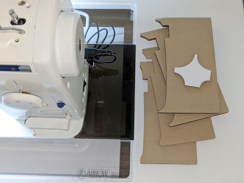
I then promised to replace the ugly cardboard filler with a less awful acrylic filler and finally got it done:

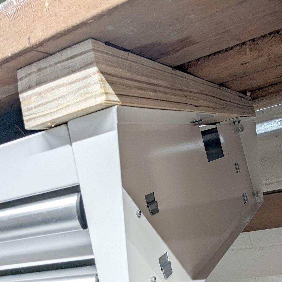
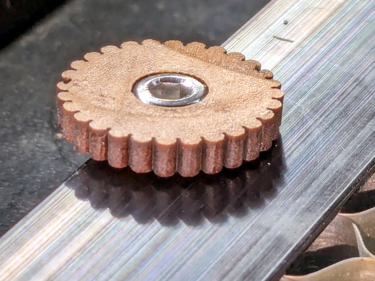
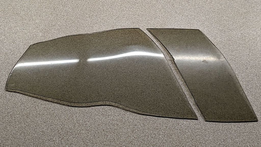
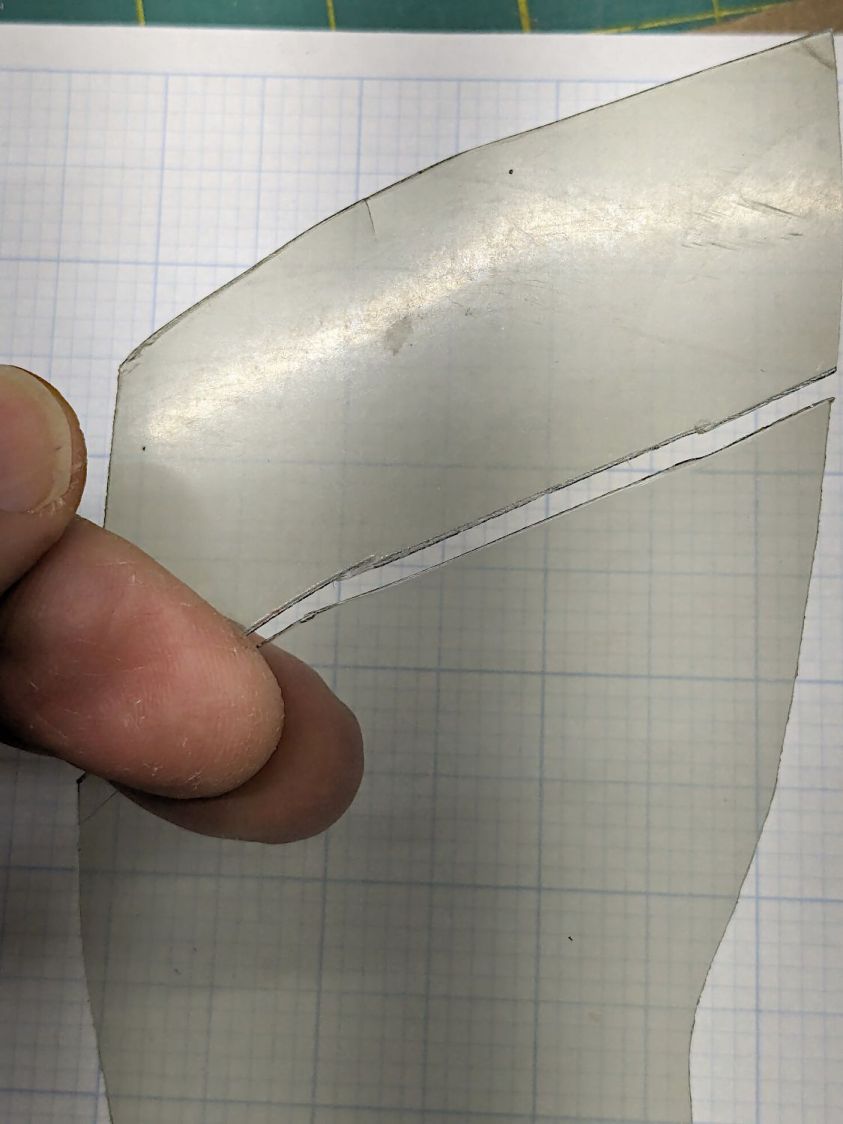
The stack of cardboard prototypes show iterative fit-and-finish improvements, with the odd shape on the top serving to measure the machine’s 25 mm corner radius by comparison with known circles.
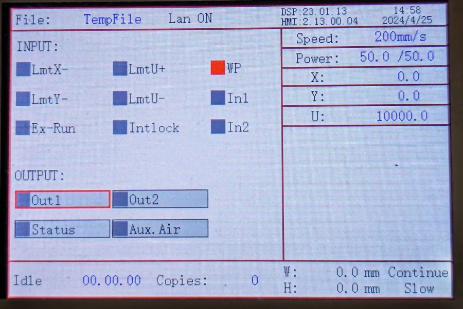
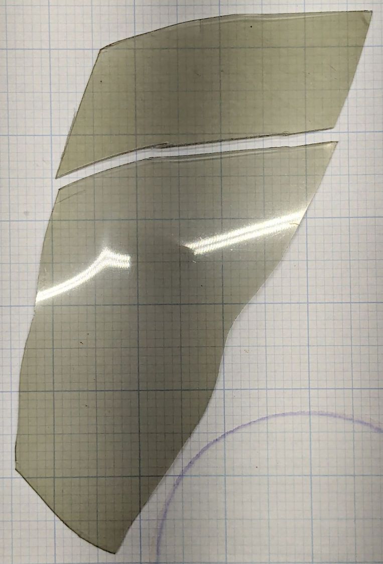
The insert filler is made from smoked gray acrylic, because I have yet to unpack the acrylic stockpile and may not, in fact, have any clear 6 mm acrylic, so we’ll regard this as a final prototype pending further developments. It did, however, confirm the laser survived the move, which was pretty much the whole point.
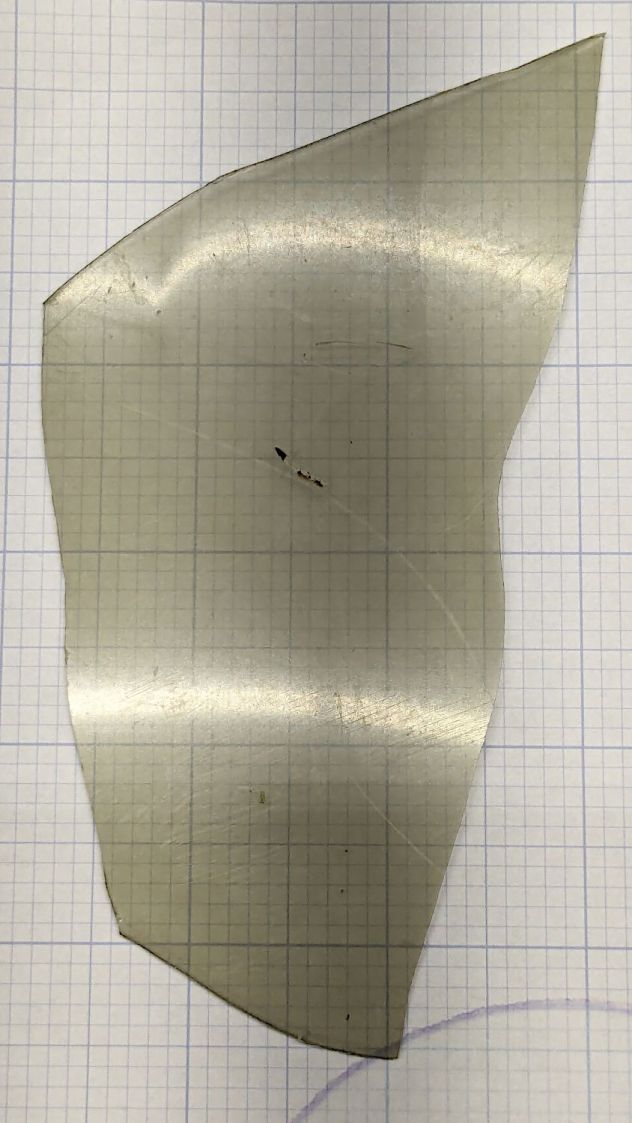
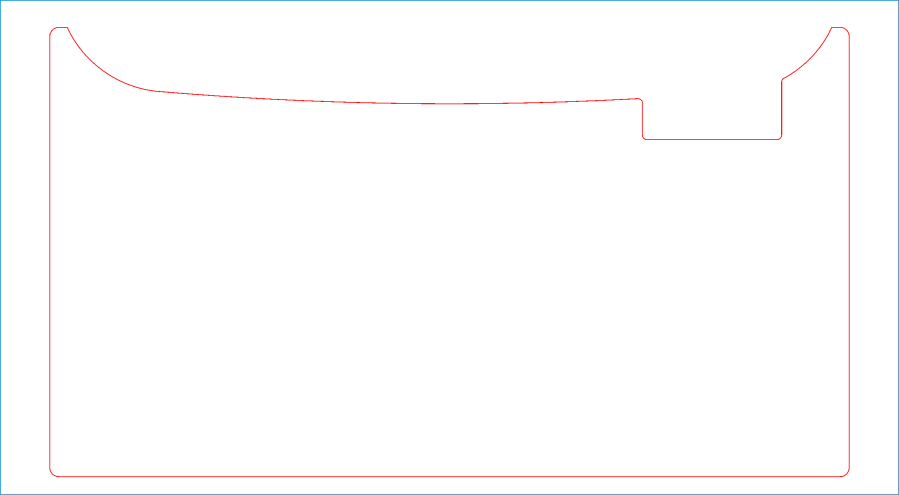
The end of the machine is not a straight line. Part of the iteration was measuring the curve’s chord height to calculate the circle’s radius, which turned out to be 760 mm:
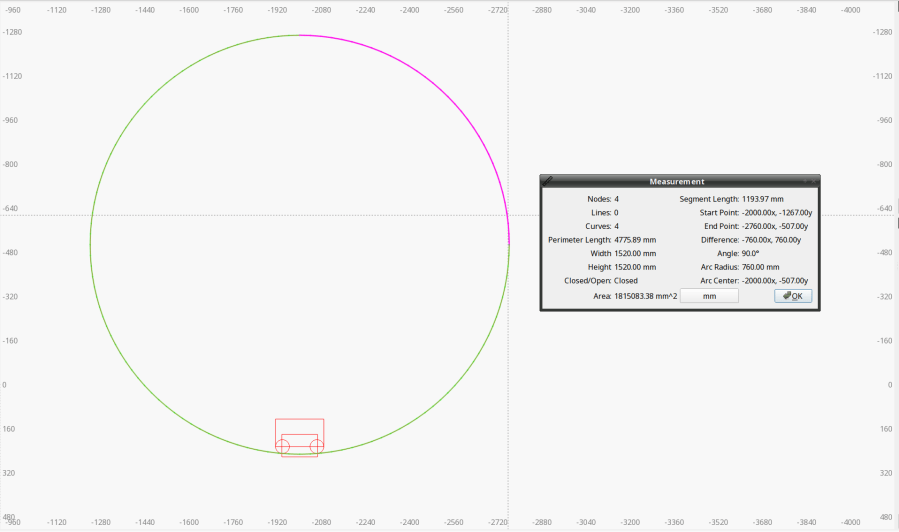
With that in hand, a few Boolean operations produced the filler shape:
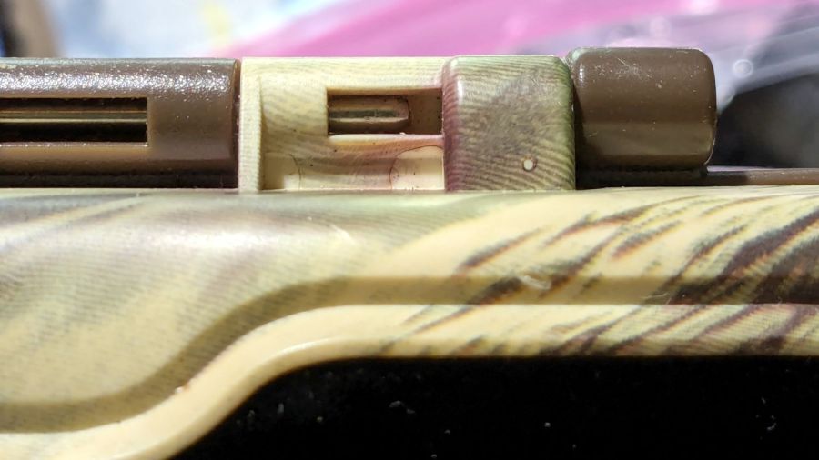
A pair of silicone bumper feet stuck to the side of the Juki hold the left edge of the filler at the proper level.
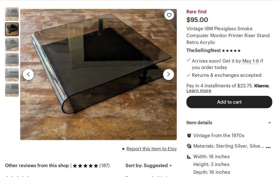
For the record, the smoked acrylic came from a fragment of a Genuine IBM Printer stand I’ve had in the scrap pile since The Good Old Days: