Ed Nisley's Blog: Shop notes, electronics, firmware, machinery, 3D printing, laser cuttery, and curiosities. Contents: 100% human thinking, 0% AI slop.
Tag: Improvements
Making the world a better place, one piece at a time
Some years back, I bought a lifetime supply of stainless steel machine screws in the usual sizes, all in 1- and 2-inch lengths. I was always cutting the things to length anyway, so why not start with nice screws?
The problem with cutting a screw is holding it securely enough that it doesn’t fly off into a far corner of the shop, but without goobering either the threads or the head.
The secret, at least as far as I can tell, is slitting a nut to make a secure clamp for sawing, filing, and grinding. I ran a slitting saw through a nut to get the result you see here. Although it’s awkward, a slit through a point means grabbing the nut on two parallel sides squeezes the slot closed: exactly what you want.
Screw firmly under control
Slit a bunch of nuts whenever you get set up to do this, because those ugly thread ends on the cut screws tend to chew ’em up. If you have any foresight, you’ll thread the nut on the screw before you cut it, but that doesn’t work for really short screws.
Yeah, a lifetime supply of all different screw sizes and all different lengths would be nice, but I really don’t spend a whole lot of my life cutting screws…
We took down the deer netting around the garden yesterday, which involves pulling a zillion staples out of the wood posts. I put some salvaged hard-drive head motor magnets to good use: one magnet inside my jacket sleeve to hold the other magnet in place, then just drop staples near them.
Shazam… no staples in the ground!
You can actually buy such things, with cute Velcro straps and all, but why? You’ve been saving those magnets for years: put ’em to use!
Two years ago I converted a $20 Thinkpad 560Z (they’re more expensive now, oddly enough) into a digital picture frame for Mary’s parents, a process documented in two of my late, lamented DDJ columns there and there. It runs a stripped-down Slackware installation that boots directly into a picture viewer, so when you turn it on you get pictures and nothing else. Well, after you get a few screens of the usual white-on-black Linux boot messages, which I think adds a certain geeky charm to a digital picture frame.
Anyhow, the thing failed just before Thanksgiving with BIOS error messages 161 and 163: its way of telling you that the lithium cell powering the clock chip has gone dead. I hadn’t replaced that cell when I did the conversion and it lasted just about exactly a decade; it was evidently the right size for the job.
Not being constrained by the confines of the original laptop case, I replaced the coin cell with a grossly oversized CR123A cylindrical lithium cell (having a bunch of them on the shelf and some holders for another project). The connector is in an awkward location, below the IDE socket’s flex-PCB cable, and both wires popped out of the connector shell when I pulled on them. So it goes.
The top picture shows the proper polarity, as seen inside another 560Z’s lithium cell compartment: red-for-positive on the right, with the circuit board positioned component side down (toward the keyboard). Our daughter did the soldering; she’s since learned about heatshrink tubing and cold joints; it’s good enough.
This picture shows the CR123A all wired up and ready to go in the picture frame. The circuit board here is component side up, so the connector wires go the other way. Notice the small trace from the red-side pin on the circuit board; that’s your clue that it’s the positive battery connection. Measure the voltage at the backside of the connector to be sure you have those miniature pins properly seated in the connector, too.
CR123A in 560Z Picture Frame
FWIW, I bought three 560Zs while they were cheap; our young lady installed Puppy Linux on the one in the top picture (hence her soldering) and seems reasonably content. They’re old & slow & cramped by contemporary standards, but just fine for most of the things you’d probably buy a fancy new netbook for.
Because nearly all of my printed circuit boards are for one-off homebrew projects, I tend to not obsess over getting the last air wire down on the copper. Instead, I route those pesky all-the-way-across-the-board stragglers on Layer 15 with big fat vias on each end, then solder a jumper wire across the board.
In effect, my Layer 15 is outside the board.
The screen shot shows a chunk of a board with some Layer 15 wires. I make ’em fat and use swooping semicircular arcs on the ends: they’re easily visible.
I don’t worry about actually routing the traces; they’re just straight lines and arcs. This generates all manner of overlaps with the rest of the components & wiring, but after I go down through the DRC list and approve ’em all one time, that’s the end of that hassle.
Two key advantages:
All the remaining air wires are genuine unrouted connections
I can print out Layer 15 separately to get a hand wiring map
I make the vias fairly large (here, 100 mils) and a unique shape (octagonal) so that I know each one should get a wire.
I usually wind up doing the power connections the same way; those vias are square. Conversely, ground vias stitching the top & bottom planes together are round; they get a short Z-wire through the board.
This probably won’t work if you’re having the boards built by an actual PCB vendor, as they’ll try to make a three-layer board or kick the board out on layout rule violations… but, on the other hand, if you can afford a four-layer board, then most likely you won’t have any trouble routing the wires.
The 6 mm stainless steel shaft I installed in late June, for reasons described there, has been working just fine.
Although the shaft has some discoloration, the idler bearing slides freely this way and that. No complaints about noises or bad shifting.
I spritzed some silicone lube on the shaft and it’s way slippery again. That’s better than petroleum lubes that tend to turn road dust into grinding compound.
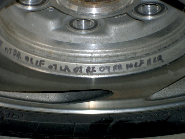
A discussion there reminded me to mention a good habit taught by my buddy Eks: when you must look something up, write the information where you’ll see it the next time you need it.
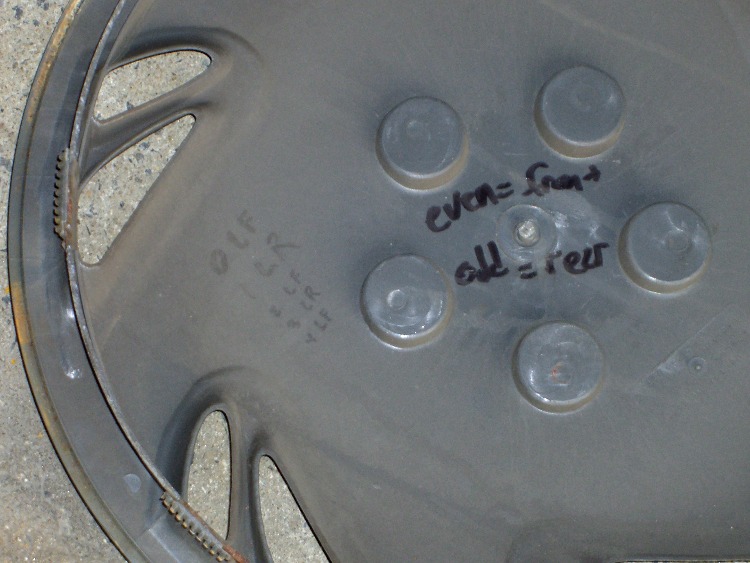
So, for example, each of the van wheels sports its own tire-rotation schedule inside the cover. When it’s time to swap tires in early spring and late autumn, I pry the cover off, read where the tire should go, and do the deed. I write ’em down four or five years at a time, so there’s not much thinking involved.
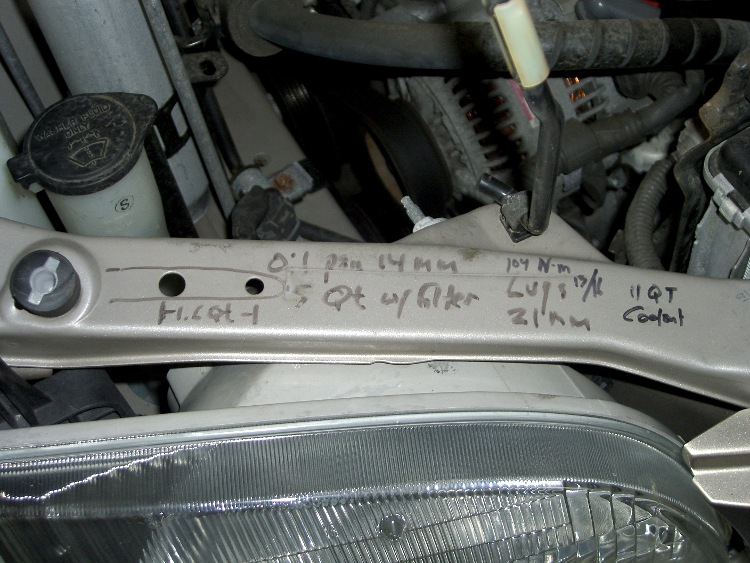
The engine compartment has all the most-often-used wrench sizes and capacities.
I write the oil change & inspection info in the maintenance schedule booklet that came with the van, although after a decade that’s pretty much full up.
Just chopped up a 5-lb lump of Provolone into 2-oz chunks for pizza, which brings this simple shop project to mind: a cheese garrotte.
It’s about a foot of 0.011-inch (call it 0.25 mm) stainless steel wire with the ends wrapped around some aluminum rod, neatly tied off with heatshrink tubing.
Usage is about what you’d expect: it cuts cheese like nothing else on earth. The only trick is maintaining a straight line, which is easier (for me, at least) when I cut vertically downward.
It’s difficult to cut all the way to the bottom and that wire is rough on the fingertips, so I tend to flip the cheese over and pull sideways for the last inch or two. Maybe not a perfect cut, but good enough.
Cheese Garrotte Handle Detail
Construction nuance: loop the wire around the handle once or twice, pass it through the hole, then do another loop before twisting the end. If you run the wire directly through the hole, it’ll break on the far-side sharp edge after a while, even when you countersink the hole.
I put a shallow groove around the handle, but that’s likely not needed. You can certainly get fancier with the handles if you like. This one is dishwasher safe, which makes up for a lot.
You really, really need heatshrink tubing over the bare wire ends, as the tip of a 11-mil stainless wire is indistinguishable from a needle.