Ed Nisley's Blog: Shop notes, electronics, firmware, machinery, 3D printing, laser cuttery, and curiosities. Contents: 100% human thinking, 0% AI slop.
Tag: Improvements
Making the world a better place, one piece at a time
The Thing-O-Matic Motherboard rides atop an Arduino Mega (with the auto-reset option disabled), drawing most of its power from the hulking ATX connector at one end. The Mega draws power from the ATX +12 V supply and produces +5 V through its on-board regulator.
As I noted there, that regulator runs surprisingly hot when fed from +12 V, even without any additional current flowing to the Mega’s pins. The solution here required another search through the parts heap, which eventually disgorged a small heatsink that was, I think, intended for a 16-pin DIP, although I obviously added the hole for some other, long-forgotten purpose.
Motherboard regulator heatsink
A bit of fin-bending to clear the (unused) power entry jack, a dab of JB Kwik epoxy, and a clamp to keep it in place while the epoxy cures:
Clamping the Motherboard regulator heatsink
You won’t have such a heatsink, but any similarly shaped chunk of metal, even without fins, should suffice. Nothing critical about it, as long as it clears the Motherboard that will be plugged atop the Mega; you’re just increasing the surface area for heat dissipation.
The Motherboard and Mega sit in the large opening across the Thing-O-Matic’s baseplate from the ATX supply’s fan intake, where they get plenty of cooling air. Do a before-and-after test with a fingertip on the regulator to feel the improvement for yourself.
This is, admittedly, just a feel-good tweak, but a cool regulator is a happy regulator. Spread the joy…
During the conversation following my original post on the MakerBot support forum, CodeRage suggested using cartridge heaters. I asked Eks about that and he said something along the lines of “Damn straight! We used ’em all over the place! Just do it!”
CodeRage plans to retrofit his MK5 head with a pair of 230 V 150 W heaters running at 120 V to get a total of 75 W. I have qualms about running line voltage around the extruder head, but it’s certainly a better solution than toasting power resistors.
The trouble with 1/2-inch models is that they don’t fit conveniently on the Thermal Core. I’d make an adapter block with a hole for the heater and two holes for the existing cap screws, but the screws don’t quite pass around a half-inch cartridge heater.
He suggested 1/8-inch heaters from Sun Electric Heater Company, which look like just the ticket except that they’re nigh onto 40 bucks a pop. Ouch.
High Temp Industries[Edit: new link 2013-12-27] has 1/4-inch heaters for under $20 that will fit in the space available. If I understand the configuration options, you can even get 12 V 30 W heaters (the same power as the existing resistors) with a 1000 °F (call it 500 °C) temperature rating.
So I think what’s needed is to get some of those heaters, machine blocks to hold them on each side of the Core, and see how that works. The heaters will fit between the resistor screw holes and the Core is just about exactly 1 inch long. What’s not to like?
This might work… except for the fact that HTI has a $150 minimum order, which is somewhat off-putting even for me. Anybody up for a group buy of ten cartridge heaters?
Note that if you swap in some cartridge heaters, you really should do the separate +12 V supply Extruder Controller hack described there.
[Update: Zach @ MBI has ordered a stack of cartridge heaters for their internal testing (he promises to send me some), plans a retrofit kit, and may become a retail source for the heaters. He reports the lead time to get heaters in bulk is something over two weeks, which is a lot longer than I expected.
In light of that, I will hold the “group order” until I have a better handle on what’s needed to retrofit cartridge heaters into the existing MK5 head, how they’ll actually work, and what PID loop retuning may be required. Once I know more about all that, we can proceed.
Having MBI handle the ordering & shipping makes sense to me!]
As nearly as I can tell, using a pair of 10 W power resistors as 30 W heating elements in the Thing-O-Matic’s MK5 Extruder Thermal Core isn’t going to work, at least if you want even minimal reliability.
The fundamental problem is that the resistor specification limits the dissipation to a few watts, tops, near 250 °C, where they must run in order to melt any of the plastic filaments.
The Thermal Core requires 20-30 W to maintain 225 °C, so each resistor must dissipate an average of 10-15 W at that temperature. That’s half of the MK5 extruder’s original design point and still nearly a factor of 10 beyond the resistor rating.
The original design runs at less than 50% duty cycle to maintain 225 °C, which agrees with my measurements:
50% of 60 W = 30 W
33% of 60 W = 20 W
If you want to run at lower power, it’s a drop-in replacement. Change the original 5 Ω resistors to 2.5 Ω resistors (from Digikey / Mouser / wherever), change the wiring to put them in series (not parallel!), and see how long they last. They’ll certainly fare better than at 30 W, but I wouldn’t expect more than a few hours of lifetime. The specs give them 1000 hours at rated power, which this certainly is not.
A series connection means that when one resistor fails, the heat goes off. The original parallel connection left one resistor carrying the load and, at 30 W, it can actually get the Core up to operating temperature and keep it there. Many folks have been baffled by that, but the diagnosis is simple. Measure the resistance of the parallel resistors at the Extruder Controller end of the wires:
5 Ω → one resistor has failed
An open circuit (infinite resistance) → both are dead
The problem with the lower power dissipation, whether from a failed resistor in the original design or my suggested change, is that the extruder head has a thermal time constant of 10-11 minutes. Lower power means a longer cold-start time; 30 W should get it up to 225 °C in about 20-30 minutes depending on the insulation. That’s not really a problem if you’re printing a series of objects, but might be objectionable for quick printing sessions.
However, when a resistor fails, the heat goes off, the plastic stiffens up, the DC extruder motor stalls, and the essentially unlimited motor current kills the A3977 driver on the extruder board. My incandescent lamp workaround may alleviate that problem: when the light goes on, check for a failed resistor.
I picked up a stock of 2-to-3 Ω power resistors and will do some further experimenting with power levels, insulation, and suchlike. This is a short-term fix to get my Thing-O-Matic running, but there’s a better long-term way to go: cartridge heaters on a modified Thermal Core, which I’ll discuss shortly.
If you arrived by search engine, jump there for my earliest guesstimates, go there to the beginning of the Thing-O-Matic hardware hackage posts, then read until you get back here. The story will, perforce, continue…
The DC motor used on the MK5 Extruder head seems unusually prone to sudden death, either by mechanical failure or something electrical. A stalled or shorted DC motor becomes a low resistance that destroys the A3977 H-bridge driver chip on the Extruder Controller board.
The power resistor reduces the voltage available to the motor, which draw something like 40 mA when unloaded and up to maybe 250 mA at full load. I don’t know what load the extruder puts on it, but at 100 mA the resistor drops 1 V, which seems excessive.
The relays seem like a nice solution, but they go clickety-clack and require actually building something, of which I’ve had quite enough lately, thank you very much.
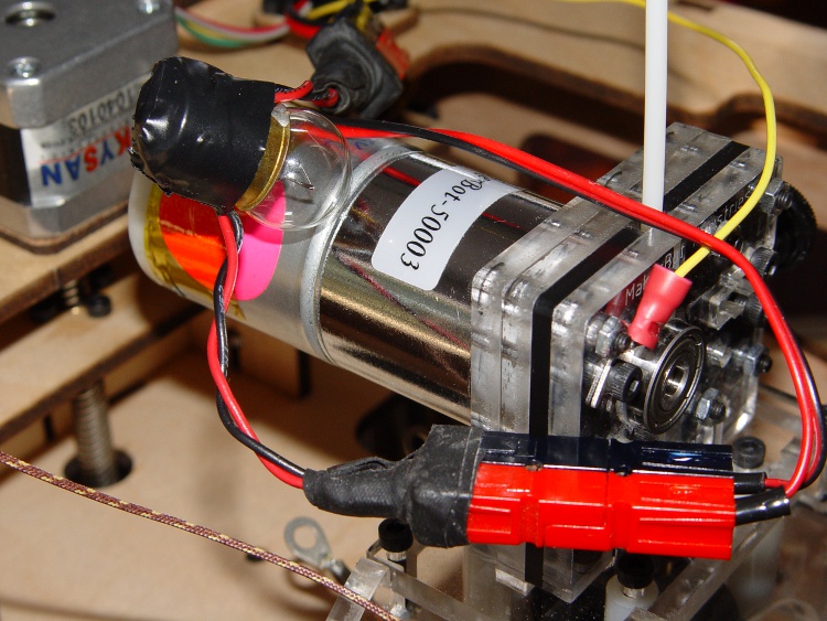
While I was mooching those lugs, my buddy Eks suggested simply putting a low-wattage 12 V incandescent lamp in series with the motor. The cold filament has a very low resistance, but limits the current when if the motor shorts out.
Extruder motor with series #89 bulb
A bit of rummaging in the Lamp Box produced an old automotive #89 lamp that allows 560 mA into a dead short, which works out to 7 W.
If the motor draws 100 mA, it drop only 100 mV: good enough!
Not finding a suitable socket in the heap, I wired it in by soldering the wires directly to the brass shell and central solder tip and taping up the mess. Next time I get near the local AutoZone I’ll pick up a socket.
The Anderson Powerpoles may look like overkill, but they make life a lot easier when you’re fiddling with the machinery all the time.
Now, the lamp won’t prevent inductive transients from blowing away those puny signal-level Zener diodes that should protect the A3977 chip, but it’s exactly what you need for long-term overload prevention.
The Thing-O-Matic touches the plastic filament in three places:
Filament Drive Frame
Extruder Thermal Core
Automated Build Platform Belt
In each case, the plastic filament slides (or oozes) along another plastic surface, which is the classic way to generate a charge of static electricity. Think of a running a comb through your hair, rubbing a cat on a balloon, shuffling across a carpet in your fuzzy slippers, or pulling off an acrylic sweater.
In addition, the X and Y stepper motors each drive a rubber-ish timing belt around a plastic roller. Non-conductive belt on plastic pulley = static charge, with metal motor pulley collecting it on the motor shaft, thence to the motor frame. The motor shafts and frames do not connect to any of the motor conductors, because in most machines the stepper motors mount to a metal chassis. The Thing-O-Matic insulates its motors on plywood or plastic sheets with no conductive path to ground.
None of those metal parts has any provision to control a static charge accumulation, which means the charge will increase until one of two events transpires:
The charge reaches an equilibrium with leakage through the air
The potential reaches air’s breakdown voltage and arcs to an adjoining metal object closer to ground potential
The former situation may be tolerable (and is most likely during the humid summer months), but the latter causes those annoying random crashes and, sometimes, hardware failures. In round numbers, air’s breakdown voltage exceeds 1 kV / mm (25 kV / inch), which explains that blue-hot spark from your fingertip to the screw on the light switch.
I added drain wires to all of those locations, using wire stripped from an old ribbon cable. There’s no particular current involved, so thin wire will work just fine. Double it over a few times to fill the barrel of the solderless connectors, though, and use some heatshrink tubing for strain relief.
The ABP platform heat spreader underneath the belt looks like a huge (and completely isolated) capacitor plate with respect to the plastic accumulating atop the belt. The wire attaches to the far right rear of the spreader and trails off with all the other ABP cabling. Yes, those are the wooden side plates, not the acrylic ones, for a reason I’ll explain when I work through my embarrassment.
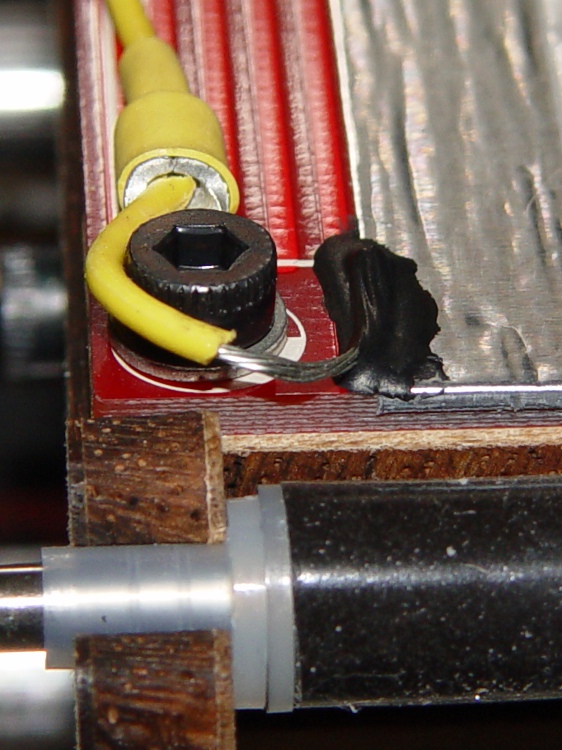
ABP Heat Spreader static drain
There’s no good way to attach a wire to the metal foil, so I used a dab of Wire Glue. The cured carbon-rich blob probably isn’t rated for protracted use at 125 °C, though, and perhaps a mechanical flange captured under one of the socket-head cap screws will be a better idea. This is a detail of the contact end; I threaded the wire through the solderless ring terminals for strain relief.
ABP static drain – detail
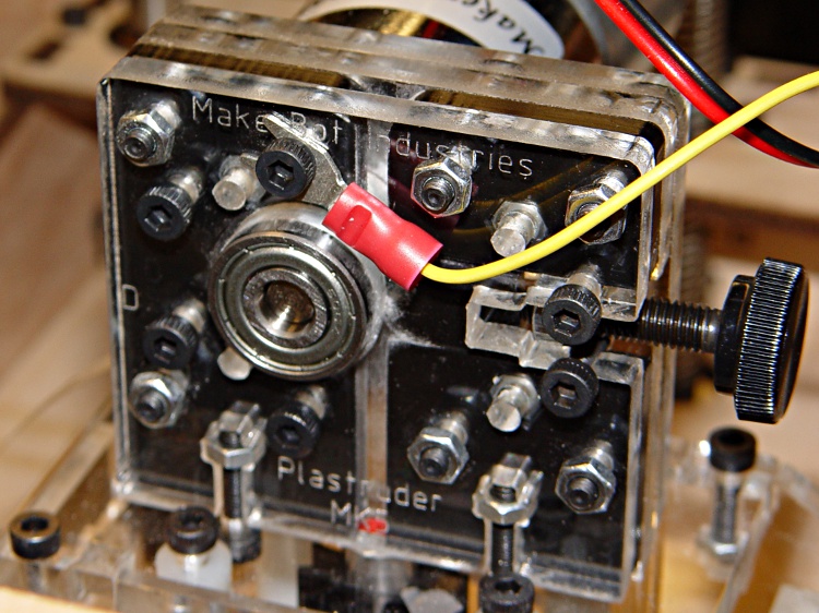
The Extruder DC motor has bolts passing entirely through the Filament Drive, so I captured a solderless connector under one head. After taking this picture, I realized that the lower motor bolt on the left side is a better location, as that one aims the connector’s open end up and to the right. Make it so.
Extruder motor static drain
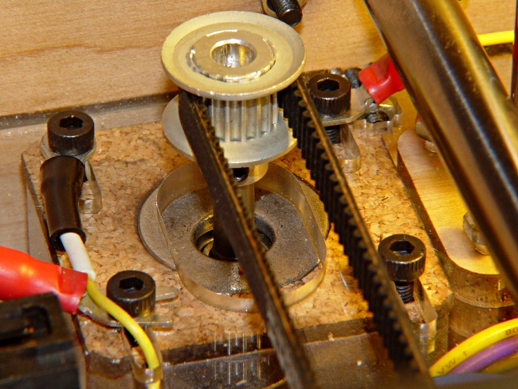
The X axis stepper motor drain wire dunks down through a motor mount slot and follows the motor winding conductors out of the housing.
X Axis static drain
The Y axis stepper motor frame serves as the connection point for the Extruder Motor and X-axis drain wires, each secured under a separate motor mounting bolt. The third wire (with black and white heatstink tubing) snakes down through the left-front motor mounting slot in the acrylic sheet above the electronics bay.
Y Axis motor with static drains
The Z axis stepper has only metal-to-metal sliding contact, so it’s presumably free of static buildup. If you’re being fussy, ground that one, too.
The Extruder Thermal Core also requires a drain wire, but that one must also handle the fault current from a resistor failure that shorts the +12 V supply directly to the Thermal Core; I’ll discuss that situation separately in a few days.
The ABP and Y Axis drain wires join a hacked-together ground point secured to the metal case of the ATX power supply metal case. You could, of course, connect these to a DC common supply lead (any Black wire), but these are, by definition, non-current-carrying leads that ought not be mixed with the power distribution. The case is a known-good grounding point that’s bonded to the AC line’s earth-ground conductor, exactly where static charges want to go.
Static drain to ATX supply connector
The connector is obviously from a cut-off Molex-style hard drive power cable with all four sockets wired together; I sacrificed a handful of Y-splitter power cables for another project a while ago. The pins are lengths of 12 AWG copper wire harvested from a length of Romex house wire, with the drain wires soldered to one end, then covered with heatstink tubing. This is a kludge, but a workable solution.
Although I think static discharge is a relatively minor contributor to the random crashes and failures, it’s easy enough to eliminate with no side effects… as long as you leave enough wire to reach the far end of the axis travel range.
Just as with the Extruder Controller, the Thing-O-Matic stepper motor driver boards derive their logic supply from the +12 V line through a 7805 linear regulator. While that works in the ideal case, it makes the logic supply vulnerable to glitches induced by motor current switching.
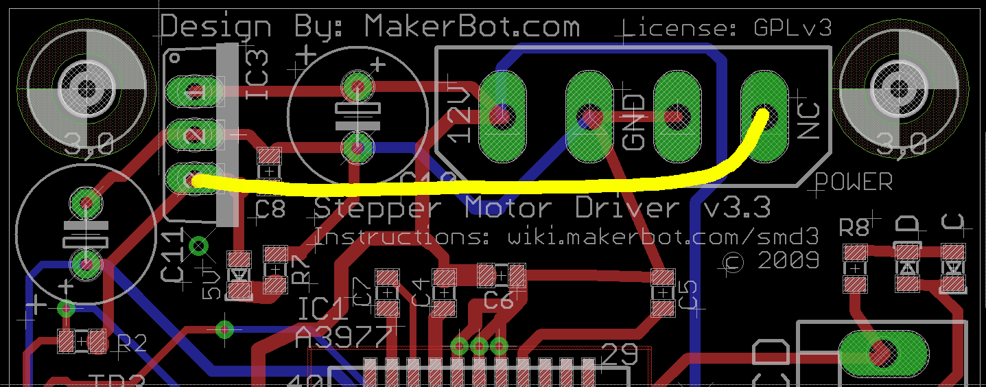
This modification gives the stepper controller chip a clean +5 V supply from the Thing-O-Matic’s ATX power supply, by the simple expedient of removing the 7805 regulator chip and connecting the +5 V from the power supply Molex-style connector to the circuit pad that was the regulator’s output pin.
This is what the modification looks like on the PCB layout.
Stepper driver board modification
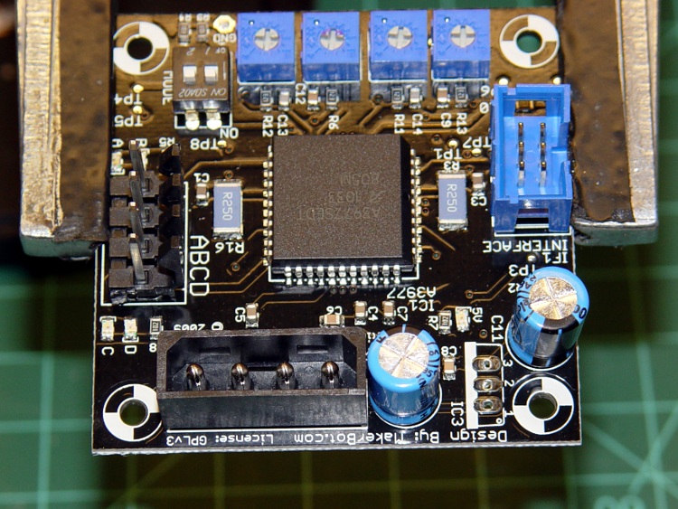
Use solder wick and a big soldering iron to de-solder the connections, then yank (gently!) the regulator off the board; you can see the outline printed on the board near the lower-right corner, between the two blue capacitors. This picture is rotated half a turn from the PCB layout shown above.
TOM stepper driver minus 7805 regulator
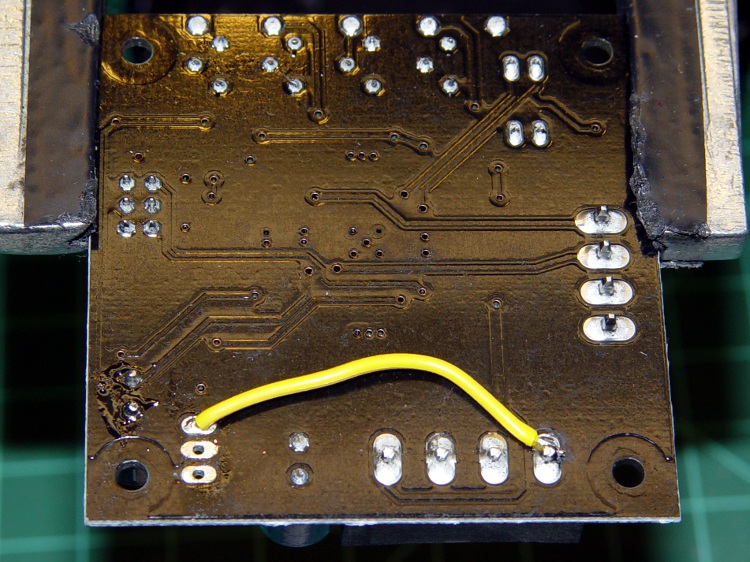
Connect a jumper from the Molex connector’s +5 V pin to Pin 3 of the 7805 regulator outline. The wire can be any size, because it carries minimal current to the driver chip’s logic circuitry; I used a strand stripped from a ribbon cable.
Put the wire on the bottom of the board, because the connector pin isn’t accessible from the top and the traces at the regulator output pad are on the top where they’ll be easy to solder.
TOM stepper driver with 5 V jumper
Repeat for all three stepper motor controller boards.
Reinstall in your Thing-O-Matic and rejoice that nothing seems to have changed. This modification should reduce the number of weird motor-control problems, although it will not prevent lost steps due to mechanical overload or excessive traverse speed.
As I described there, a single +12 V Molex connector pin must supply too much current to the Extruder Controller Board. Fortunately, the stock Thing-O-Matic ATX power supply has a 4-pin connector that, in its normal PC environment, provides +12 V power to a high-end video board. This modification hacks that connector to provide separate +12 V power wires to the Extruder and Heated Build Platform heater MOSFETs, thus removing 11 A of current from the Extruder Controller PCB.
That current normally passes from the +12 V pin of the Molex-style connector to the screw terminals securing the Red heater wires. The corresponding Black / Blue wires connect to screw terminals that pass the current to power MOSFETs that switch the heaters on and off. Disconnecting the “Red” screw terminals from their PCB traces and connecting them directly to the +12 V from the hacked video connector, then connecting the corresponding return wires to the PCB near the MOSFET Source pins, is what’s needed.
This is what the change looks like on the PCB layout. The four yellow angles mark pins soldered to the board, the yellow arc is a new jumper wire, and the three purple dashes represent trace cuts. It’s not all that complicated, but it will certainly void whatever warranty you think might otherwise apply to the board.
Extruder Controller MOSFET modifications
The blue line between the row of screw terminal pins and the edge of the circuit board conducts +12 V power from the Molex connector to the A3949 DC motor driver chip. This modification doesn’t affect that connection: you must not sever that PCB trace.
Disconnected +12 V screw terminal pin
Cut the short traces between the screw terminal pins and the adjacent +12 V trace along the edge; I used a scalpel blade while watching through a microscope. You’ll certainly cut into the ground plane on either side of the trace, so you’ll see copper on all sides. Use a multimeter to verify that the terminal pin no longer connects to the +12 V Molex pin (the leftmost one as shown above) and that a stray copper curl hasn’t shorted it to the ground plane (either of the two center Molex pins). The result will look like this at each of the three screw terminal pins.
You should fill the gouges with an insulator to prevent future heartache and confusion. I used some of my shop assistant’s Citrus Punch nail polish; the glitter is entirely gratuitous. Wrap a narrow strip of Kapton tape along the edge to prevent shorts to the PCB ground planes from the pins you’re about to add.
Insulated PCB trace cuts
The corresponding ground connections go on the top surface of the board, near the MOSFET Source pins. There’s just enough space between the ICSP connector and the Gate traces to make this happen. Scrape the black solder mask off the PCB to reveal the clean copper ground plane below, leaving a narrow strip along the edge of the ICSP connector. Basically, you’re obliterating the URL that aims you at the board’s documentation.
Extruder Controller with scraped-off solder mask
Take care to not gouge through the copper plane and take extreme care to avoid the Gate traces and vias. I ground a flat end on that scalpel blade and used it as a scraper.
Lay the board aside and work on the ATX supply’s four-pin video power connector, which looks like this.
ATX power supply video connector
Note that there’s another four-pin connector that you removed from the end of the hulking 20-pin connector that plugs into the Thing-O-Matic Motherboard. That one has four different wire colors (black, red, orange, yellow) and won’t work here!
Remove the pins from the connector housing. There’s a special tool that does this, but I used a defunct crochet needle. The trick is to poke a very skinny tool between the stamped-metal socket and the plastic housing to push in the spring tab that locks the socket in place. There are two spring tabs on opposite sides of each socket. This operation goes smoothly if you pull gently on the wire while poking the tabs; you can feel the socket move when the tab slides out of position.
The end result will look like this, with a tab on the top surface.
Dismantled video power connector
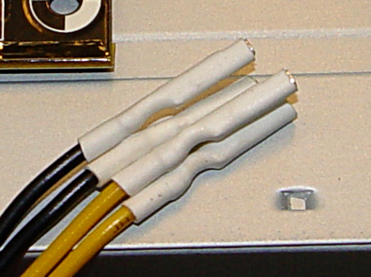
Clip off the two protruding tabs that hold the socket in the plastic housing against the tabs. Apply some heat-shrink tubing around each socket to get four little teeny connectors:
Insulated video connector sockets
The sockets mate, albeit with some persuasion, to 45-mil (1.14 mm) square pins that are not the smaller 25-mil pins found on pin header strips. My parts heap disgorged a handful of suitable right-angle pins in plastic strips, something like those; failing that, I’d harvest and gut a connector from dead PC system board. You could probably use some 16 or 18 AWG solid wire in a pinch, but the current is rather high for an impromptu arrangement.
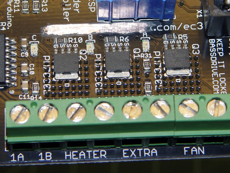
Solder two pins to the screw terminals on bottom of the PCB, angled slightly so the upright parts pass between the screw terminal openings on the side. The pins are on the Heater (for Extruder head) and Extra (for Heated Platform) terminals, with the jumper wire connecting the latter to the Fan (ABP belt motor) terminal; all are on the +12 V terminal of their respective pairs.
The ABP belt motor connects to the other terminal of the Fan pair, which leads directly to the MOSFET Drain. You could omit the yellow jumper wire, but that’d be confusing if you ever wanted to use that MOSFET in the same way as the others.
Extruder Controller with +12 V to screw terminals
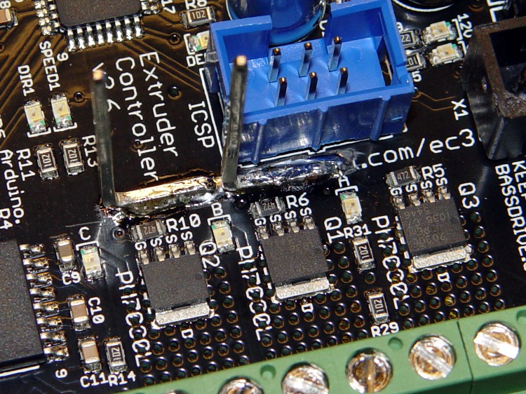
Solder the other two right-angle pins to the cleared strip on the top of the board, tinning the ground plane and pins before you solder them together. Don’t block access to the ICSP connector; you never know when you might need it! I put the angled ends of the pins to the right, as viewed from the screw terminal strip, which put the right-most pin exactly at the corner of the connector shell with barely enough room for the wire with socket + heatshrink. The end result should look like this:
Extruder Controller with added ground pins
Do a trial fit: plug in the four wires from the video power cable, noting that the Black wires connect to the top-side pins and the Yellow wires connect to the pins at the screw terminals. I trimmed the pins so they exactly fit into their sockets.
Extruder Controller with separate +12 V supplies
This is certainly not the most robust construction method in the world. In particular, the pins on the top surface depend on structural solder to the ground plane; they have a fairly large area in contact with the board, but if you manage to apply enough force you can probably wreck the Extruder Controller board.
Put the board back in the Thing-O-Matic, connect the modified video power wires, and plug / screw all the usual connections. Button it up, fire it up, and it should work exactly as before… but with better reliability.
This modification should reduce the number of glitch-induced transient failures by moving most of the transient energy off the board; the remaining paths are very short. It will not correct excessive heat in the MOSFETS and does not cure the DC motor overcurrent jam / driver failure problems.