The Smell of Molten Projects in the Morning

Ed Nisley's Blog: Shop notes, electronics, firmware, machinery, 3D printing, laser cuttery, and curiosities. Contents: 100% human thinking, 0% AI slop.

Tag: Improvements

Making the world a better place, one piece at a time

  • Thing-O-Matic / MK5 Extruder: Static Control

    The Thing-O-Matic touches the plastic filament in three places:

    • Filament Drive Frame
    • Extruder Thermal Core
    • Automated Build Platform Belt

    In each case, the plastic filament slides (or oozes) along another plastic surface, which is the classic way to generate a charge of static electricity. Think of a running a comb through your hair, rubbing a cat on a balloon, shuffling across a carpet in your fuzzy slippers, or pulling off an acrylic sweater.

    In addition, the X and Y stepper motors each drive a rubber-ish timing belt around a plastic roller. Non-conductive belt on plastic pulley = static charge, with metal motor pulley collecting it on the motor shaft, thence to the motor frame. The motor shafts and frames do not connect to any of the motor conductors, because in most machines the stepper motors mount to a metal chassis. The Thing-O-Matic insulates its motors on plywood or plastic sheets with no conductive path to ground.

    None of those metal parts has any provision to control a static charge accumulation, which means the charge will increase until one of two events transpires:

    • The charge reaches an equilibrium with leakage through the air
    • The potential reaches air’s breakdown voltage and arcs to an adjoining metal object closer to ground potential

    The former situation may be tolerable (and is most likely during the humid summer months), but the latter causes those annoying random crashes and, sometimes, hardware failures. In round numbers, air’s breakdown voltage exceeds 1 kV / mm (25 kV / inch), which explains that blue-hot spark from your fingertip to the screw on the light switch.

    I added drain wires to all of those locations, using wire stripped from an old ribbon cable. There’s no particular current involved, so thin wire will work just fine. Double it over a few times to fill the barrel of the solderless connectors, though, and use some heatshrink tubing for strain relief.

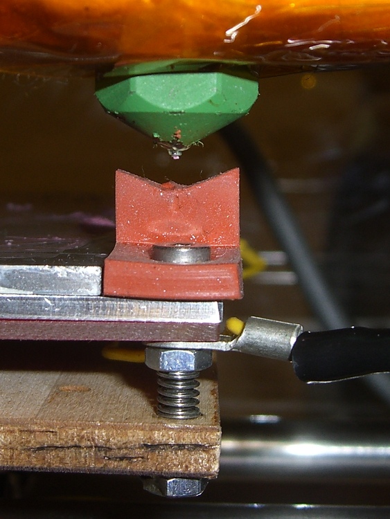
    The ABP platform heat spreader underneath the belt looks like a huge (and completely isolated) capacitor plate with respect to the plastic accumulating atop the belt. The wire attaches to the far right rear of the spreader and trails off with all the other ABP cabling. Yes, those are the wooden side plates, not the acrylic ones, for a reason I’ll explain when I work through my embarrassment.

    ABP Heat Spreader static drain
    ABP Heat Spreader static drain

    There’s no good way to attach a wire to the metal foil, so I used a dab of Wire Glue. The cured carbon-rich blob probably isn’t rated for protracted use at 125 °C, though, and perhaps a mechanical flange captured under one of the socket-head cap screws will be a better idea. This is a detail of the contact end; I threaded the wire through the solderless ring terminals for strain relief.

    ABP static drain - detail
    ABP static drain – detail

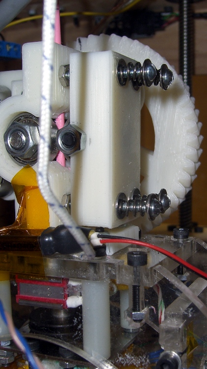
    The Extruder DC motor has bolts passing entirely through the Filament Drive, so I captured a solderless connector under one head. After taking this picture, I realized that the lower motor bolt on the left side is a better location, as that one aims the connector’s open end up and to the right. Make it so.

    Extruder motor static drain
    Extruder motor static drain

    The X axis stepper motor drain wire dunks down through a motor mount slot and follows the motor winding conductors out of the housing.

    X Axis static drain
    X Axis static drain

    The Y axis stepper motor frame serves as the connection point for the Extruder Motor and X-axis drain wires, each secured under a separate motor mounting bolt. The third wire (with black and white heatstink tubing) snakes down through the left-front motor mounting slot in the acrylic sheet above the electronics bay.

    Y Axis motor with static drains
    Y Axis motor with static drains

    The Z axis stepper has only metal-to-metal sliding contact, so it’s presumably free of static buildup. If you’re being fussy, ground that one, too.

    The Extruder Thermal Core also requires a drain wire, but that one must also handle the fault current from a resistor failure that shorts the +12 V supply directly to the Thermal Core; I’ll discuss that situation separately in a few days.

    The ABP and Y Axis drain wires join a hacked-together ground point secured to the metal case of the ATX power supply metal case. You could, of course, connect these to a DC common supply lead (any Black wire), but these are, by definition, non-current-carrying leads that ought not be mixed with the power distribution. The case is a known-good grounding point that’s bonded to the AC line’s earth-ground conductor, exactly where static charges want to go.

    Static drain to ATX supply connector
    Static drain to ATX supply connector

    The connector is obviously from a cut-off Molex-style hard drive power cable with all four sockets wired together; I sacrificed a handful of Y-splitter power cables for another project a while ago. The pins are lengths of 12 AWG copper wire harvested from a length of Romex house wire, with the drain wires soldered to one end, then covered with heatstink tubing. This is a kludge, but a workable solution.

    Although I think static discharge is a relatively minor contributor to the random crashes and failures, it’s easy enough to eliminate with no side effects… as long as you leave enough wire to reach the far end of the axis travel range.

  • Thing-O-Matic: Stepper Driver Logic Supply

    Just as with the Extruder Controller, the Thing-O-Matic stepper motor driver boards derive their logic supply from the +12 V line through a 7805 linear regulator. While that works in the ideal case, it makes the logic supply vulnerable to glitches induced by motor current switching.

    This modification gives the stepper controller chip a clean +5 V supply from the Thing-O-Matic’s ATX power supply, by the simple expedient of removing the 7805 regulator chip and connecting the +5 V from the power supply Molex-style connector to the circuit pad that was the regulator’s output pin.

    This is what the modification looks like on the PCB layout.

    Stepper driver board modification
    Stepper driver board modification

    Use solder wick and a big soldering iron to de-solder the connections, then yank (gently!) the regulator off the board; you can see the outline printed on the board near the lower-right corner, between the two blue capacitors. This picture is rotated half a turn from the PCB layout shown above.

    TOM stepper driver minus 7805 regulator
    TOM stepper driver minus 7805 regulator

    Connect a jumper from the Molex connector’s +5 V pin to Pin 3 of the 7805 regulator outline. The wire can be any size, because it carries minimal current to the driver chip’s logic circuitry; I used a strand stripped from a ribbon cable.

    Put the wire on the bottom of the board, because the connector pin isn’t accessible from the top and the traces at the regulator output pad are on the top where they’ll be easy to solder.

    TOM stepper driver with 5 V jumper
    TOM stepper driver with 5 V jumper

    Repeat for all three stepper motor controller boards.

    Reinstall in your Thing-O-Matic and rejoice that nothing seems to have changed. This modification should reduce the number of weird motor-control problems, although it will not prevent lost steps due to mechanical overload or excessive traverse speed.

  • Thing-O-Matic: Extruder Controller MOSFET Supplies

    As I described there, a single +12 V Molex connector pin must supply too much current to the Extruder Controller Board. Fortunately, the stock Thing-O-Matic ATX power supply has a 4-pin connector that, in its normal PC environment, provides +12 V power to a high-end video board. This modification hacks that connector to provide separate +12 V power wires to the Extruder and Heated Build Platform heater MOSFETs, thus removing 11 A of current from the Extruder Controller PCB.

    That current normally passes from the +12 V pin of the Molex-style connector to the screw terminals securing the Red heater wires. The corresponding Black / Blue wires connect to screw terminals that pass the current to power MOSFETs that switch the heaters on and off. Disconnecting the “Red” screw terminals from their PCB traces and connecting them directly to the +12 V from the hacked video connector, then connecting the corresponding return wires to the PCB near the MOSFET Source pins, is what’s needed.

    This is what the change looks like on the PCB layout. The four yellow angles mark pins soldered to the board, the yellow arc is a new jumper wire, and the three purple dashes represent trace cuts. It’s not all that complicated, but it will certainly void whatever warranty you think might otherwise apply to the board.

    Extruder Controller MOSFET modifications
    Extruder Controller MOSFET modifications

    The blue line between the row of screw terminal pins and the edge of the circuit board conducts +12 V power from the Molex connector to the A3949 DC motor driver chip. This modification doesn’t affect that connection: you must not sever that PCB trace.

    Disconnected +12 V screw terminal pin
    Disconnected +12 V screw terminal pin

    Cut the short traces between the screw terminal pins and the adjacent +12 V trace along the edge; I used a scalpel blade while watching through a microscope. You’ll certainly cut into the ground plane on either side of the trace, so you’ll see copper on all sides. Use a multimeter to verify that the terminal pin no longer connects to the +12 V Molex pin (the leftmost one as shown above) and that a stray copper curl hasn’t shorted it to the ground plane (either of the two center Molex pins). The result will look like this at each of the three screw terminal pins.

    You should fill the gouges with an insulator to prevent future heartache and confusion. I used some of my shop assistant’s Citrus Punch nail polish; the glitter is entirely gratuitous. Wrap a narrow strip of Kapton tape along the edge to prevent shorts to the PCB ground planes from the pins you’re about to add.

    Insulated PCB trace cuts
    Insulated PCB trace cuts

    The corresponding ground connections go on the top surface of the board, near the MOSFET Source pins. There’s just enough space between the ICSP connector and the Gate traces to make this happen. Scrape the black solder mask off the PCB to reveal the clean copper ground plane below, leaving a narrow strip along the edge of the ICSP connector. Basically, you’re obliterating the URL that aims you at the board’s documentation.

    Extruder Controller with scraped-off solder mask
    Extruder Controller with scraped-off solder mask

    Take care to not gouge through the copper plane and take extreme care to avoid the Gate traces and vias. I ground a flat end on that scalpel blade and used it as a scraper.

    Lay the board aside and work on the ATX supply’s four-pin video power connector, which looks like this.

    ATX power supply video connector
    ATX power supply video connector

    Note that there’s another four-pin connector that you removed from the end of the hulking 20-pin connector that plugs into the Thing-O-Matic Motherboard. That one has four different wire colors (black, red, orange, yellow) and won’t work here!

    Remove the pins from the connector housing. There’s a special tool that does this, but I used a defunct crochet needle. The trick is to poke a very skinny tool between the stamped-metal socket and the plastic housing to push in the spring tab that locks the socket in place. There are two spring tabs on opposite sides of each socket. This operation goes smoothly if you pull gently on the wire while poking the tabs; you can feel the socket move when the tab slides out of position.

    The end result will look like this, with a tab on the top surface.

    Dismantled video power connector
    Dismantled video power connector

    Clip off the two protruding tabs that hold the socket in the plastic housing against the tabs. Apply some heat-shrink tubing around each socket to get four little teeny connectors:

    Insulated video connector sockets
    Insulated video connector sockets

    The sockets mate, albeit with some persuasion, to 45-mil (1.14 mm) square pins that are not the smaller 25-mil pins found on pin header strips. My parts heap disgorged a handful of suitable right-angle pins in plastic strips, something like those; failing that, I’d harvest and gut a connector from dead PC system board. You could probably use some 16 or 18 AWG solid wire in a pinch, but the current is rather high for an impromptu arrangement.

    Solder two pins to the screw terminals on bottom of the PCB, angled slightly so the upright parts pass between the screw terminal openings on the side. The pins are on the Heater (for Extruder head) and Extra (for Heated Platform) terminals, with the jumper wire connecting the latter to the Fan (ABP belt motor) terminal; all are on the +12 V terminal of their respective pairs.

    The ABP belt motor connects to the other terminal of the Fan pair, which leads directly to the MOSFET Drain. You could omit the yellow jumper wire, but that’d be confusing if you ever wanted to use that MOSFET in the same way as the others.

    Extruder Controller with +12 V to screw terminals
    Extruder Controller with +12 V to screw terminals

    Solder the other two right-angle pins to the cleared strip on the top of the board, tinning the ground plane and pins before you solder them together. Don’t block access to the ICSP connector; you never know when you might need it! I put the angled ends of the pins to the right, as viewed from the screw terminal strip, which put the right-most pin exactly at the corner of the connector shell with barely enough room for the wire with socket + heatshrink. The end result should look like this:

    Extruder Controller with added ground pins
    Extruder Controller with added ground pins

    Do a trial fit: plug in the four wires from the video power cable, noting that the Black wires connect to the top-side pins and the Yellow wires connect to the pins at the screw terminals. I trimmed the pins so they exactly fit into their sockets.

    Extruder Controller with separate +12 V supplies
    Extruder Controller with separate +12 V supplies

    This is certainly not the most robust construction method in the world. In particular, the pins on the top surface depend on structural solder to the ground plane; they have a fairly large area in contact with the board, but if you manage to apply enough force you can probably wreck the Extruder Controller board.

    Put the board back in the Thing-O-Matic, connect the modified video power wires, and plug / screw all the usual connections. Button it up, fire it up, and it should work exactly as before… but with better reliability.

    This modification should reduce the number of glitch-induced transient failures by moving most of the transient energy off the board; the remaining paths are very short. It will not correct excessive heat in the MOSFETS and does not cure the DC motor overcurrent jam / driver failure problems.

  • Thing-O-Matic: Extruder Controller Power Supply Improvement

    The Thing-O-Matic Extruder Controller uses a 7805 linear regulator to produce +5 V logic power from the +12 V input. Unfortunately, the board’s +12 V supply input is grossly overloaded: a single 20 AWG wire and Molex-style connector pin must supply several simultaneously active high-power loads:

    • 5 A → Extruder heater
    • 6 A → Build Platform heater
    • 1-2 A → Extruder motor

    The return current path to the ATX supply uses two pins and wires, so it contributes half as much to the problem. Molex connector pins aren’t rated for that much current (11 A @ 30 °C rise), so the +12 V supply arrives at the board in poor condition.

    Worse, the brushes on the DC Extruder motor introduce large switching transients, even without PWM speed-control chopping. The Extruder and Build Platform heaters also present somewhat inductive loads to their MOSFET switches that create significant switching transients. The 7805 regulator isn’t well-suited to removing high-voltage transients; its bandwidth isn’t high enough.

    This modification gives the Extruder Controller clean +5 V logic power by removing the 7805 regulator chip and connecting the +5 V pin at the power supply Molex-style connector directly to the PCB pad that was the regulator’s output pin.

    This is what the modification looks like on the PCB layout.

    Extruder Controller board modification
    Extruder Controller board modification

    Unsolder the regulator and remove it, which will reveal the outline printed on the circuit board. This picture is rotated a quarter-turn counterclockwise from the PCB layout shown above.

    Extruder Controller minus 7805 regulator
    Extruder Controller minus 7805 regulator

    You’ll need a beefy soldering iron or an Old Skool soldering gun to make headway on the 7805′s center pin, because it’s firmly attached to the ground plane on both sides of the circuit board. A solder sucker and desoldering braid will come in handy to remove excess solder before extracting the regulator.

    Then connect a jumper from the Molex connector’s +5 V pin to Pin 3 of the 7805 regulator outline. The wire can be any size, because it carries minimal current to the logic circuitry; I used a strand stripped from a ribbon cable.

    Put the wire on the bottom of the board, because the connector pin isn’t accessible from the top. However, the trace at the regulator output pad is on the bottom where it’ll butt against the wire insulation, so make sure there’s a solder fillet between the wire and the pad.

    Extruder Controller with 5 V jumper
    Extruder Controller with 5 V jumper

    Reinstall the Extruder controller and marvel that nothing seems to have changed.

    The next modification to this board will move the heater power supplies off the board, but it’s a much more aggressive hack. This simple change should eliminate the random resets and crashes that seem to be plaguing the stock Extruder Controller board; it will not prevent burning out the DC motor controller chip.

  • High-Visibility Dremel Chuck Wrench

    Having just spent far too long finding this amid the rubble atop the Machine Shop bench, I wrapped some tape around the handle:

    • flare orange to find it on the bench
    • retroreflective to find it under the bench

    Now it lives on a hook in the floor joist over the bench, right next to the hook where the tool + flexy shaft hangs most of the time.

    High-viz Dremel chuck wrench
    High-viz Dremel chuck wrench
  • Recycled Heatsink: Hole Plugs

    I actually did get around to plugging the holes directly under the power resistors on those heatsinks, even though we all know it makes absolutely no difference whatsoever.

    Heatsink hole plugs
    Heatsink hole plugs

    Start with some 5/16-inch aluminum rod, face and center-drill one end, turn down about two inches to a scant 0.200 inch diameter, saw off a stub on the end.

    Grab the stub in the 3-jaw Sherline chuck clamped to the mill table and slice off 0.240 inch slugs using a teeny slitting saw and manual CNC.

    No pix of the setup, for reasons that made sense at the time, but that project gives you the general idea.

    Repeat three times to get 3 x 6 = 18 slugs, plus a few spares.

    Clean out the heatsink holes, clamp a bar (covered with tape) on the flat side, butter up the holes & slugs with JB Weld epoxy, squish ’em in place, scrape off the excess epoxy after a few hours.

    Actually, this was a thinly veiled excuse to get my shop assistant some Quality Shop Time on the lathe and CNC mill. Wouldn’t you do the same?

  • Atom D520: Config Files for Smoother Sherline Stepping

    The dual-core-ness of the D520, as set up there, allows a distinct improvement in the EMC2 BASE_PERIOD setting, which is exactly why I undertook this adventure.

    The 100 µs period I used on the Dell Dimension 4550 ensured the occasional long-latency burps wouldn’t cause much trouble… and they didn’t. The setup used the HAL step generator’s ability to supply a single pulse within one base period, so the maximum stepping rate was 1/100 µs = 10 k steps / second.

    However, that also determines the granularity of speed changes, so the controller can only drive the motors at multiples of the basic 100 µs without interpolating. For example, the four fastest step rates are:

    • 1/100 µs = 10 k step/sec
    • 1/200 µs =5 k step/sec
    • 1/300 µs = 3.3 k step/sec
    • 1/400 µs = 2.5 k step/sec

    The motors have 200 major steps / revolution and run in quarter-step mode: 800 microsteps / revolution. The axes have 20 turn-per-inch leadscrews, thus requiring 16 k step pulses per inch of travel.

    That means the corresponding traverse speeds are (step/sec) / (step/inch):

    • 10 k step/sec -> 0.625 in/sec = 37 in/min
    • 5 k step/sec -> 0.313 in/sec = 18.75 in/min
    • 3.3 k step/sec -> 0.206 in/sec = 12.37 in/min
    • 2.5 k step/sec -> 0.156 in/sec = 9.37 in/min

    Those are fairly large jumps between the speeds, which means the motor acceleration when the step rate changes is fairly high. HAL interpolates by bunching groups of pulses, but higher resolution is better.

    The Atom CPU has latencies under 10 µs, with no large burps that I’ve seen so far, so I set the BASE_PERIOD to 50 µs. However, that required changing the HAL step generator to produce a pulse during two successive periods (one high, one low) to keep the pulses wide enough for the motor controller. That means the highest step rate is still 10 k steps/sec and the top speed is still 37 inch/min.

    However, HAL can now adjust the period in smaller increments with lower acceleration between the jumps. The four fastest rates are now:

    • 1/100 µs = 10 k step/sec -> 0.625 in/sec = 37 in/min
    • 1/150 µs =6.7 k step/sec -> 0.417 in/sec = 25 in/min
    • 1/200 µs = 5 k step/sec -> 0.313 in/sec = 18.75 in/min
    • 1/250 µs = 4 k step/sec -> 0.250 in/sec = 15 in/min

    A stock Sherline CNC milling machine is rated for 22 inch/min (0.37 inch/sec) rapid motion on all three axes. That means the maximum step rate is

    • (0.37 inch/sec) * (16 k step/in) = 5.9 kHz

    Quite some years ago, I rebuilt my Sherline controller box to reduce its electrical and acoustic noise, then did a clean-room reimplementation of the firmware in the PIC microcontrollers. After the dust settled, my firmware could handle 8 k steps / sec, which works out to 0.5 in/sec = 30 in/min.

    That turns out to be slightly more aggressive than the whole lashup can tolerate; I can hear the motors take occasional hits as they miss the odd step at 30 inch/min.

    So I set the overall MAX_LINEAR_VELOCITY = 0.400 inch/sec = 24 inch/min, which is also the MAX_VELOCITY for both X and Y. The Z axis, as always, is happier with a bit slower top speed: 0.333 inch/sec = 20 inch/min. The maximum step rate is 0.4 x 16 k = 6.4 kHz, comfortably under the controller’s upper limit.

    The MAX_ACCELERATION for X and Y = 5.0 in/sec2, with Z at 3.0. STEPGEN_MAXACCEL for each axis is twice that; I have each axis set for a few mils of backlash compensation.

    With all that in mind, the changed configuration files look like this, with the others remaining as described there.

    Sherline.hal, with the new stepgen pulse specs

    # Generated by stepconf at Sat Aug 23 12:10:22 2008
    # If you make changes to this file, they will be
    # overwritten when you run stepconf again
    loadrt trivkins
    loadrt [EMCMOT]EMCMOT base_period_nsec=[EMCMOT]BASE_PERIOD servo_period_nsec=[EMCMOT]SERVO_PERIOD traj_period_nsec=[EMCMOT]SERVO_PERIOD key=[EMCMOT]SHMEM_KEY num_joints=[TRAJ]AXES
    loadrt probe_parport
    loadrt hal_parport cfg="0x378 out"
    setp parport.0.reset-time 60000
    loadrt stepgen step_type=0,0,0,0
    loadrt pwmgen output_type=0
    
    addf parport.0.read base-thread
    addf stepgen.make-pulses base-thread
    addf pwmgen.make-pulses base-thread
    addf parport.0.write base-thread
    addf parport.0.reset base-thread
    
    addf stepgen.capture-position servo-thread
    addf motion-command-handler servo-thread
    addf motion-controller servo-thread
    addf stepgen.update-freq servo-thread
    addf pwmgen.update servo-thread
    
    net spindle-cmd <= motion.spindle-speed-out => pwmgen.0.value
    net spindle-enable <= motion.spindle-on => pwmgen.0.enable
    net spindle-pwm <= pwmgen.0.pwm
    setp pwmgen.0.pwm-freq 100.0
    setp pwmgen.0.scale 1166.66666667
    setp pwmgen.0.offset 0.114285714286
    setp pwmgen.0.dither-pwm true
    net spindle-cw <= motion.spindle-forward
    
    net estop-out => parport.0.pin-01-out
    net xdir => parport.0.pin-02-out
    net xstep => parport.0.pin-03-out
    setp parport.0.pin-03-out-reset 0
    setp parport.0.pin-04-out-invert 1
    net ydir => parport.0.pin-04-out
    net ystep => parport.0.pin-05-out
    setp parport.0.pin-05-out-reset 0
    setp parport.0.pin-06-out-invert 1
    net zdir => parport.0.pin-06-out
    net zstep => parport.0.pin-07-out
    setp parport.0.pin-07-out-reset 0
    net adir => parport.0.pin-08-out
    net astep => parport.0.pin-09-out
    setp parport.0.pin-09-out-reset 0
    net spindle-cw => parport.0.pin-14-out
    net spindle-pwm => parport.0.pin-16-out
    net xenable => parport.0.pin-17-out
    
    setp stepgen.0.position-scale [AXIS_0]SCALE
    setp stepgen.0.steplen 1
    setp stepgen.0.stepspace 1
    setp stepgen.0.dirhold 60000
    setp stepgen.0.dirsetup 60000
    setp stepgen.0.maxaccel [AXIS_0]STEPGEN_MAXACCEL
    net xpos-cmd axis.0.motor-pos-cmd => stepgen.0.position-cmd
    net xpos-fb stepgen.0.position-fb => axis.0.motor-pos-fb
    net xstep <= stepgen.0.step
    net xdir <= stepgen.0.dir
    net xenable axis.0.amp-enable-out => stepgen.0.enable
    
    setp stepgen.1.position-scale [AXIS_1]SCALE
    setp stepgen.1.steplen 1
    setp stepgen.1.stepspace 1
    setp stepgen.1.dirhold 60000
    setp stepgen.1.dirsetup 60000
    setp stepgen.1.maxaccel [AXIS_1]STEPGEN_MAXACCEL
    net ypos-cmd axis.1.motor-pos-cmd => stepgen.1.position-cmd
    net ypos-fb stepgen.1.position-fb => axis.1.motor-pos-fb
    net ystep <= stepgen.1.step
    net ydir <= stepgen.1.dir
    net yenable axis.1.amp-enable-out => stepgen.1.enable
    
    setp stepgen.2.position-scale [AXIS_2]SCALE
    setp stepgen.2.steplen 1
    setp stepgen.2.stepspace 1
    setp stepgen.2.dirhold 60000
    setp stepgen.2.dirsetup 60000
    setp stepgen.2.maxaccel [AXIS_2]STEPGEN_MAXACCEL
    net zpos-cmd axis.2.motor-pos-cmd => stepgen.2.position-cmd
    net zpos-fb stepgen.2.position-fb => axis.2.motor-pos-fb
    net zstep <= stepgen.2.step
    net zdir <= stepgen.2.dir
    net zenable axis.2.amp-enable-out => stepgen.2.enable
    
    setp stepgen.3.position-scale [AXIS_3]SCALE
    setp stepgen.3.steplen 1
    setp stepgen.3.stepspace 1
    setp stepgen.3.dirhold 60000
    setp stepgen.3.dirsetup 60000
    setp stepgen.3.maxaccel [AXIS_3]STEPGEN_MAXACCEL
    net apos-cmd axis.3.motor-pos-cmd => stepgen.3.position-cmd
    net apos-fb stepgen.3.position-fb => axis.3.motor-pos-fb
    net astep <= stepgen.3.step
    net adir <= stepgen.3.dir
    net aenable axis.3.amp-enable-out => stepgen.3.enable
    
    net estop-out <= iocontrol.0.user-enable-out
    net estop-out => iocontrol.0.emc-enable-in
    
    loadusr -W hal_manualtoolchange
    net tool-change iocontrol.0.tool-change => hal_manualtoolchange.change
    net tool-changed iocontrol.0.tool-changed <= hal_manualtoolchange.changed
    net tool-number iocontrol.0.tool-prep-number => hal_manualtoolchange.number
    net tool-prepare-loopback iocontrol.0.tool-prepare => iocontrol.0.tool-prepared
    

    Sherline.ini, with new periods, speeds, and accelerations

    # Ed Nisley - KE4ZNU
    # Just do not run stepconf ever again...
    
    [EMC]
    MACHINE = Sherline-XYZA
    DEBUG = 0
    RS274NGC_STARTUP_CODE = G21 G40 G49 G54 G80 G90 G92.1 G94 G97 G98
    
    [DISPLAY]
    DISPLAY = axis
    EDITOR = gedit
    GEOMETRY = AXYZ
    POSITION_OFFSET = RELATIVE
    POSITION_FEEDBACK = ACTUAL
    MAX_FEED_OVERRIDE = 3.0
    INTRO_GRAPHIC = /home/ed/emc2/configs/Sherline-XYZA/Sherline.gif
    INTRO_TIME = 3
    #PROGRAM_PREFIX = /mnt/bulkdata/
    PROGRAM_PREFIX = ~/emc2/nc_files
    #INCREMENTS = .1in .05in .01in .005in .001in .0005in .0001in
    INCREMENTS = 10 mm, 1 mm, 0.1 mm, 90 deg, 45 deg, 10 deg
    
    [FILTER]
    PROGRAM_EXTENSION = .py Python Script
    py = python
    
    [TASK]
    TASK = milltask
    CYCLE_TIME = 0.010
    
    [RS274NGC]
    PARAMETER_FILE = emc.var
    
    [EMCMOT]
    EMCMOT = motmod
    SHMEM_KEY = 111
    COMM_TIMEOUT = 1.0
    COMM_WAIT = 0.010
    BASE_PERIOD = 50000
    SERVO_PERIOD = 1000000
    
    [HAL]
    HALUI=halui
    HALFILE = Sherline.hal
    HALFILE = custom.hal
    HALFILE = Logitech_Gamepad.hal
    POSTGUI_HALFILE = custom_postgui.hal
    
    [TRAJ]
    AXES = 4
    COORDINATES = X Y Z A
    MAX_ANGULAR_VELOCITY = 45.00
    DEFAULT_ANGULAR_VELOCITY = 36.0
    LINEAR_UNITS = inch
    ANGULAR_UNITS = degree
    CYCLE_TIME = 0.010
    DEFAULT_VELOCITY = 0.400
    MAX_LINEAR_VELOCITY = 0.400
    POSITION_FILE =	lastposition.txt
    NO_FORCE_HOMING = 1
    
    [EMCIO]
    EMCIO = io
    CYCLE_TIME = 0.100
    TOOL_TABLE = Sherline.tbl
    TOOL_CHANGE_AT_G30 = 1
    
    [AXIS_0]
    TYPE = LINEAR
    MAX_VELOCITY = 0.400
    MAX_ACCELERATION = 5.0
    STEPGEN_MAXACCEL = 10.0
    SCALE = 16000.0
    FERROR = 0.05
    MIN_FERROR = 0.01
    MIN_LIMIT = -1.0
    MAX_LIMIT = 9.5
    BACKLASH = 0.003
    HOME_IS_SHARED = 1
    HOME_SEQUENCE = 2
    HOME_SEARCH_VEL = 0.3
    HOME_LATCH_VEL = 0.016
    HOME_FINAL_VEL = 0.4
    HOME_OFFSET = 9.1
    HOME = 4.5
    
    [AXIS_1]
    TYPE = LINEAR
    MAX_VELOCITY = 0.400
    MAX_ACCELERATION = 5.0
    STEPGEN_MAXACCEL = 10.0
    SCALE = 16000.0
    FERROR = 0.05
    MIN_FERROR = 0.01
    MIN_LIMIT = -0.5
    MAX_LIMIT = 4.90
    BACKLASH = 0.003
    HOME_IS_SHARED = 1
    HOME_SEQUENCE = 1
    HOME_SEARCH_VEL = -0.3
    HOME_LATCH_VEL = -0.016
    HOME_FINAL_VEL = 0.4
    HOME_OFFSET = 0.0
    HOME = 4.0
    
    [AXIS_2]
    TYPE = LINEAR
    MAX_VELOCITY = 0.333
    MAX_ACCELERATION = 3.0
    STEPGEN_MAXACCEL = 6.0
    SCALE = 16000.0
    FERROR = 0.05
    MIN_FERROR = 0.01
    MIN_LIMIT = 0.0
    MAX_LIMIT = 6.930
    BACKLASH = 0.005
    HOME_IS_SHARED = 1
    HOME_SEQUENCE = 0
    HOME_SEARCH_VEL = 0.200
    HOME_LATCH_VEL = 0.016
    HOME_FINAL_VEL = 0.3
    HOME_OFFSET = 6.93
    HOME = 6.5
    
    [AXIS_3]
    TYPE = ANGULAR
    ###WRAPPED_ROTARY = 1
    MAX_VELOCITY = 40.0
    MAX_ACCELERATION = 250.0
    STEPGEN_MAXACCEL = 275.0
    SCALE = 160.0
    FERROR = 1
    MIN_FERROR = .25
    MIN_LIMIT = -999999999.9
    MAX_LIMIT =  999999999.9
    HOME_SEARCH_VEL = 0
    HOME_LATCH_VEL = 0
    HOME = 0.0