Ed Nisley's Blog: Shop notes, electronics, firmware, machinery, 3D printing, laser cuttery, and curiosities. Contents: 100% human thinking, 0% AI slop.
Tag: Improvements
Making the world a better place, one piece at a time
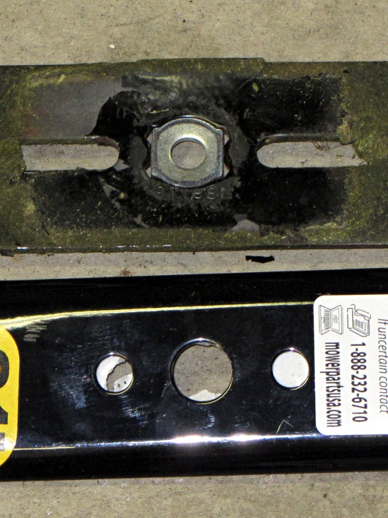
So I picked up a new mower blade that sported a sticker claiming it probably fit my Craftsman mower. Got it home, took off the old blade, and it actually fit the mower; the holes matched the hub’s drive pins, although the bolt hole was oversized.
The old blade was a replacement, too, with a square hub hole and an adapter to fit the bolt. The blade had slots for the drive pins, so the adapter was required.
Seeing as how nothing exceeds like excess, I rummaged around in the heap to find something that would serve as an adapter in the central hole. It’s not really necessary, but I’m that type of guy.
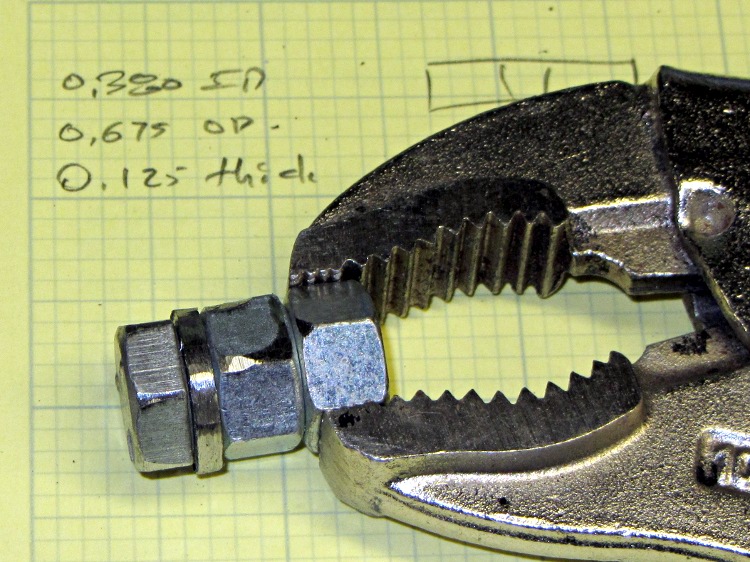
As it turned out, an ordinary lockwasher for a 3/8 inch bolt was just about perfect. I crunched one in a short bolt with two nuts jammed in place …
Lockwasher ground for mower blade
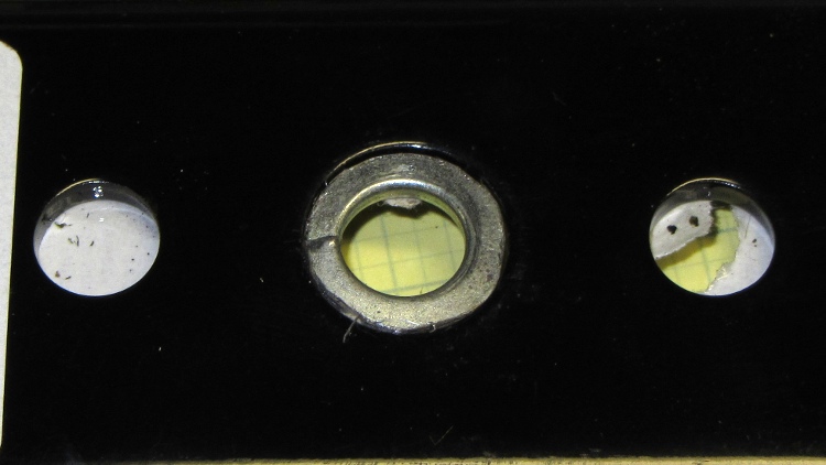
… introduced it to the coarse side of Mr Grinding Wheel, and, after a few shots with a hammer, it became a perfect fit:
Lockwasher in blade
Bolted it on the mower, put in two hours of yard aerobics, and it worked just fine. Sliced the top off a root that evaded the attention of the previous blade, too.
Unlike most folks, it seems, I’m a big fan of automatic wiping at the start of each print. It’s particularly important with the Z-min platform height switch, because a little ABS snot on the end of the nozzle changes the initial layer thickness in a bad way: additional height at the switch reduces the first layer thickness.
The problem is that the default wiper position at the right front corner of the platform requires a cutout in the build plates and the wiper gets in the way of the first several layers of very large objects.
I’m thinking of moving the wiper to the center rear of the platform, sticking out beyond the plates. There’s a convenient hole in the HBP platform for a mounting bracket, it won’t hit either of the Z axis rods at either end of the X axis travel, and maybe it’ll be low enough to stay out of the way.
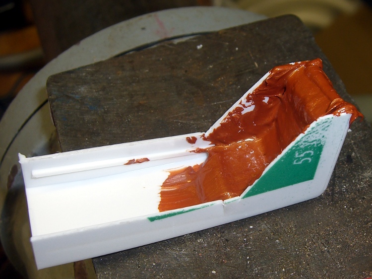
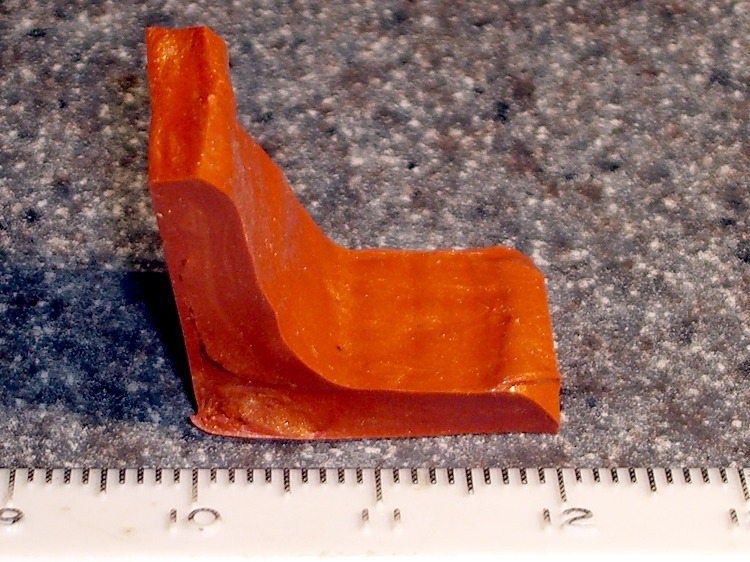
In the nature of a prototype, I smoothed a layer of Permatex copper-loaded silicone gasket compound into the corner of an old dental floss container to get a more-or-less right-angled shape:
Silicone-copper wiper – curing
That’s much thicker than the usual gasket that you’re supposed to make from this stuff, so I let it cure for a few days before popping it out, then another few days to get into that big lump in the corner. As expected, it doesn’t stick to polyethylene at all.
After trimming, it looks more like a wiper blade, albeit with Orc Engineering artistic sensibilities:
Trimmed wiper
It’s fairly soft stuff, which is what you want in a gasket, so it’ll require support on the bottom and back. Right now, I’m not sure which is which, which is why I troweled the stuff into the mold with one thick side and one thin side.
A simple bent-metal bracket should do the trick, with a screw in a hole punched through the wiper blade mounting the whole affair to the HBP plywood. Of course, it’d be even better with a printed bracket.
The silicone’s temperature rating goes up to 700 C for intermittent use, which sounds about right for this application.
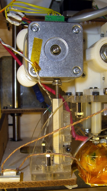
In the process of tracking down the source of those Reversal zits, I noticed the motor mount flexed slightly as it reversed. That could produce a bit of backlash, so I added a quick-and-dirty support strut under the motor.
It’s a threaded standoff with a screw in one end. The nut (secured with a dab of Loctite) lets a wrench do the height adjustment. It just stands there, held in place by compression loading.
Unfortunately, it really didn’t have much of an effect on the problem, about which I’ll say more in a bit.
Stepper extruder design has advanced during the last half year, so I may print up the latest iteration of Greg’s Extruder. There’s also a beefy NEMA 17 on its way around the curve of the planet that might suffice as a direct-drive extruder motor along the lines of the MBI MK6 StepStruder motor, but with lower winding resistance for better performance.
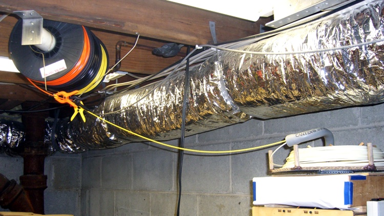
Three spools of filament just arrived and needed a home; up to this point, I’ve been using the Lazy Susan Filament Spool for loose bundles atop the Thing-O-Matic. Until I use the last of the loose filament, which could take a while, I figured I could tack the spools to the floor joists.
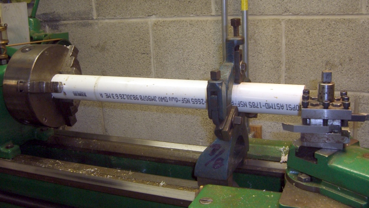
It turns out 1-1/2 inch PVC drain pipe fits perfectly through the spool bore, so I squared up the ends of a chunk long enough to span the floor joists at a convenient distance from the printer. That steady rest doesn’t see a lot of use, but when I need it, I need it bad:
Turning spool axle
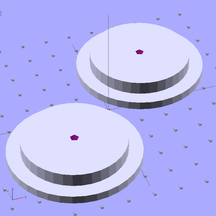
The endplate solid model looks about like you’d expect:
Filament spool axle endplates
I could turn those things from two chunks of plate, but this is much neater; a 3D printer makes short work of custom-sized parts.
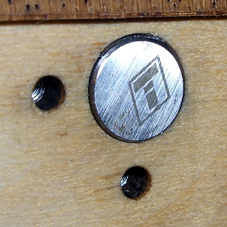
The two pegs of yellow filament keep the axle endplate from turning on the central screw (and, inevitably, unscrewing themselves); add glue in the blind holes and trim to fit with a flush-cutting nipper. The aluminum brackets come from a pile I’ve been using for years: as almost always, the holes were in exactly the right places.
Filament spool axle endplate
With all that in hand, up it went:
Overhead filament spools
I bent some coat hanger wire into a guide bar with three eyelets for the filaments, plus another chunk to hold the guide in position. Three small (color coordinated!) clamps prevent the unused filament from unwinding.
I’m not completely happy with this arrangement, because there’s not enough control over the filament energy: the coil around each spool wants to expand into a tangle exactly the size and shape of the Basement Laboratory and there’s not a lot preventing that. I think a variation on tbuser’s Spool Guard theme might be in order: let the filament expand within a tightly enclosed space around each spool.
The OpenSCAD source code:
// Filament spool shaft adapter
// Ed Nisley KE4ZNU July 2011

include </home/ed/Thing-O-Matic/lib/MCAD/units.scad>

Layout = "Show";					// Show or Build

//-- Extrusion parameters

ThreadThick = 0.33;
ThreadWT = 2.0;
ThreadWidth = ThreadThick * ThreadWT;

HoleWindage = 0.1;			// enlarge hole dia by this amount
Protrusion = ThreadThick;

//-- End Plate dimensions

PlateOD = 51.0;
PlateThick = ThreadThick * ceil(3.0 / ThreadThick);

AxleID = 40.0;
AxleThick = ThreadThick * ceil(5.0 / ThreadThick);

HoleSpacing = 0.75 * inch;

StubDepth = ThreadThick * ceil(2.5 / ThreadThick);
StubDia = 3.0;

ScrewDepth = PlateThick + AxleThick;

PrintOffset = 0.8*PlateOD/2;			// fraction of dia to offset objects for printing

Tap6_32 = 0.1065 * inch;
Clear6_32 = 0.1495 * inch;
Head6_32 = 0.270 * inch;
Head6_32Thick = 0.097 * inch;
Nut6_32Dia = 0.361 * inch;		// across points
Nut6_32Thick = 0.114 * inch;

//----------------------
// Useful routines

module PolyCyl(Dia,Height,ForceSides=0) {			// based on nophead's polyholes

  Sides = (ForceSides != 0) ? ForceSides : (ceil(Dia) + 2);

  FixDia = Dia / cos(180/Sides);

  cylinder(r=(FixDia + HoleWindage)/2,
           h=Height,
	   $fn=Sides);
}

PegSize = 1.0;

module ShowPegGrid(Size) {
	for (x=[-5:5])
	  for (y=[-5:5])
		translate([x*10,y*10,Size/2])
		  %cube(Size,center=true);

}

//----------------------
// Single endplate

module AxleEndPlate() {

  difference() {
	union() {
	  cylinder(r=PlateOD/2,h=PlateThick,$fa=10);
	  translate([0,0,PlateThick])
		cylinder(r=AxleID/2,h=AxleThick,$fa=10);
	}

	translate([0,0,-Protrusion])
	  PolyCyl(Tap6_32,ScrewDepth + 2*Protrusion);

	for(y=[-HoleSpacing,HoleSpacing])
	  translate([0,y,-Protrusion])
		PolyCyl(StubDia,StubDepth + Protrusion);

  }

}

//----------------------
// Lash it together

if (Layout == "Show")
	ShowPegGrid(PegSize);

translate([-PrintOffset,-PrintOffset,0]) AxleEndPlate();

translate([PrintOffset,PrintOffset,0]) AxleEndPlate();
The aluminum build platform plates remain both flat and level, but the outline and test extrusions are consistently thin by 0.05 to 0.10 mm in the right rear corner and thick by about the same amount in the right front. That means the rear corner is too high and the front corner is too low, but the whole left side is flat to within my ability to measure it.
The effect is significant, because I’m laying down the first layer at 10 mm/s with a layer thickness of 0.33 mm; the first layer looks exactly like all the other layers in the object. With the middle of the plate at 0.33 mm below the nozzle, the fill can be cramped at 0.23 mm and sparse at 0.43 mm. The long-term Z-min switch repeatability seems to be no better than 0.05 mm, so when the midline goes below 0.30 mm, the higher rear corner really crowds the plastic.
Given that the left side is level front-to-back, the only way a flat plate can appear non-flat is if the X and Y axis rods aren’t quite parallel: the stage rolls or yaws as it moves.
That could indicate a bent rod, but the last time I rolled those rods on a surface plate, they’re perfectly straight. Maybe something horrible has happened, but any stress capable of bending one of those rods will wreck the printer in passing.
Alas, a static platform adjustment can’t fix a dynamic motion, but tweaking the rods to be (more) parallel could reduce the problem. I tried visualizing the possible causes and cures, then decided to stop thinking so much, just change something, then measure the results.
Why my head exploded:
The thickness varies from front-to-back, so the Y axis rods are non-parallel, which should affect both the left and right sides. But the left side is perfectly level and the right side is not.
The thickness varies from left-to-right, so the X axis rods are non-parallel, which should affect both the front and back sides. But they vary oppositely: the front tilts down to the right and the back tilts up to the right. The midline from left to right, however, is level to within my ability to measure it.
I had shimmed the rear X axis rod quite some time ago, so I decided to try a simple adjustment: move the shim from top to bottom. The picture shows the 0.4 mm shim in its original location at the top of the rod; the edge is barely visible. For lack of anything smarter, I moved the shim to the bottom of the rod to push the end upward.
Shazam! The results of a test extrusion in units of 0.01 mm:
39
35
40
35
40
33
36
[Update: Typo in the rear-left was 49, should be 39. Drat!]
Which says it’s give-or-take 0.05 mm around the middle, with the rear-left corner now a tad low; bear in mind that 0.05 mm is about the limit of my measurement ability. It’s off to a good start, anyway, and we’ll see how it fares over the next few weeks.
Methinks if you’re serious about this 3D printing thing, you need a printer with real axis alignment adjustments and enough stability to make them meaningful. Nophead uses custom code that tweaks the G-Code’s Z-axis coordinates on the fly based on an initial three-point probe, which is a wonderful solution that’s not in the cards for RepG. EMC2 could incorporate that in the kinematics module, but at the moment it does just XY leadscrew mapping. It’s simpler, albeit more expensive on a per-machine basis, to get the mechanical alignment right the first time.
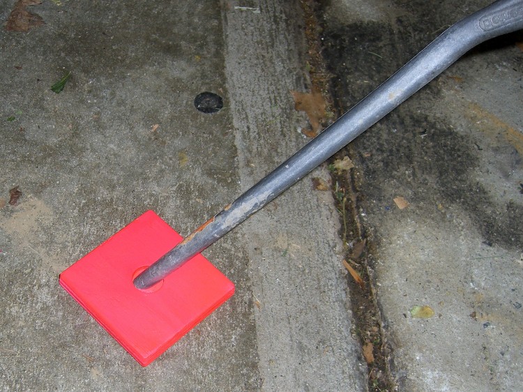
Having managed to mislay my dingy yellow kickstand plate, I made two more and this time hit ’em with fluorescent red paint. Ought to be unforgettable for another few years…
In theory, you’re supposed to apply a white undercoat. I hosed ’em down with many drippy, runny coats of red and it’s all good. This ain’t art and they get thrown on the ground, so what’s the point of being fancy?
The backside of the Lenovo N5901 Mini Wireless Keyboard (which arrived with the aforementioned Q150) has a black-on-black power switch with ON and OFF legends (yes, I think they’re backwards, too) embossed in the matte black case: under anything less intense than enhanced interrogation lighting, you (well, I) can’t determine the switch position.
Of course, the myriad certifications / ratings / labels required for compliance with all the regulations are perfectly legible:
Lenovo Mini Keyboard – enhanced labels
Working a dab of white correction fluid into the letters makes them blindingly obvious; the smudges around the letters will wear off in short order.
I should probably add a bit of white to the switch background as well.