Ed Nisley's Blog: Shop notes, electronics, firmware, machinery, 3D printing, laser cuttery, and curiosities. Contents: 100% human thinking, 0% AI slop.
Tag: Improvements
Making the world a better place, one piece at a time
That didn’t matter with a three-foot pipe attached directly to the downspouts, but, as part of the driveway project, I routed the house storm drains and wall footing drain pipes about 20 feet down from the new retaining wall, with the two joining into a single outlet. There’s a cleanout plug on the storm drain line, but the footing drain consists of about 50 feet of corrugated and perforated tubing that would be just about the finest possible chipmunk habitat.
In principle, one would simply glue a grate into the final fitting and be done with it, but leaves from the gutter will pack behind the grate, so it must be removable. Leaving the grate loose means it’ll pop out at the slightest provocation and, most likely, roll another hundred feet down the driveway into the street.
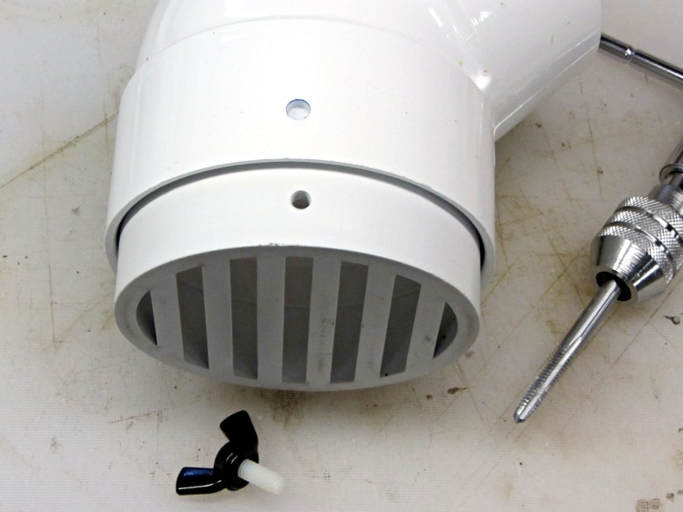
Rather than coping with that, I drilled a clearance hole in the elbow and tapped a matching hole in the grate:
Drain pipe grate – hole tapping
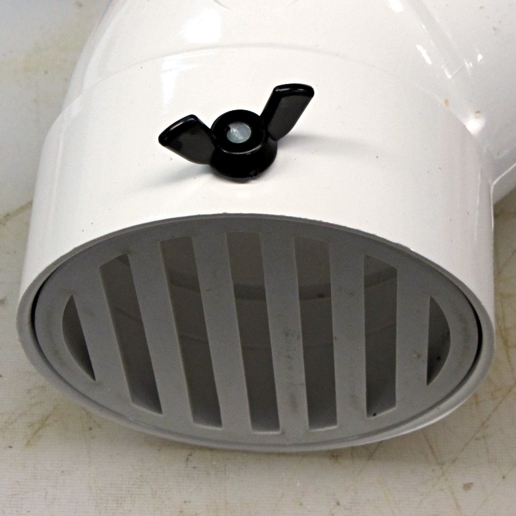
I have a few white nylon 1/4-20 cutoffs from the bike fairing clamps, so I wrecked the threads on one and jammed it into a black nylon thumbscrew:
Drain pipe grate – thumbscrew
Now, of course, the critters can still climb down the drainpipes from the gutters and set up housekeeping in the plumbing, but I’m not putting grates where I must climb onto the roof to clear them. A chipmunk dropped from two stories will scamper away; I’d never walk again.
The tiny Lenovo Q150 has become the dedicated Windows box for running TurboTax this season. In earlier years, I used the Token Windows Laptop through a remote desktop session that appears on a Xubuntu desktop, but the Q150 runs rings around the old laptop.
This time, no matter what I tried, I couldn’t connect to the Windows 7 desktop on the Q150 from my Xubuntu desktop. The usual search results suggested Windows configuration settings that didn’t quite match what the Q150 provided; a bit more searching revealed that Windows 7 Home flavors of the OS (this one is Home Premium) lack the Remote Desktop Protocol server required to export the desktop. The Q150 could act as a client that controlled another machine’s desktop server, but not the other way around.
The suggested solutions required applying patches, in the form of EXE files downloaded from sketchy websites, or dropping in replacement DLLs obtained from similar sites. All that seems like Bad Practice, particularly for a Windows box used to prepare our taxes, and I was unwilling to proceed along those lines.
Instead, I fetched UltraVNC, installed it on the Q150, and it works perfectly. Remmina occasionally requires a resize-window-to-match-server at startup and then it’s all good.
From what I hear, Windows 7 doesn’t display the classic Blue Screen of Death nearly so often as before, although I did manage to lock it up during the course of this adventure. That’s OK, I can still use my favorite Windows wallpaper image:
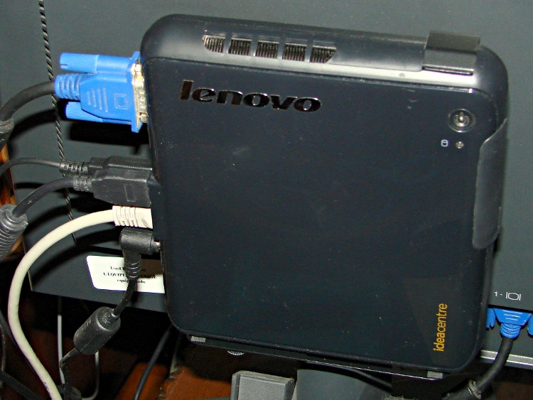
A permutation of our *cough* computing resources put the diminutive Lenovo Ideacentre Q150 flat on a desktop, where it was at risk of falling off due to the weight of the cables. It came with a VESA monitor mount bracket designed under the assumption that monitor manufacturers would provide an unused VESA socket and a completely separate desk stand mount, which turned out to be incorrect for all of the monitors in my collection. The IBM (pre Lenovo) monitor it was now driving, however, had exposed screws on its VESA mount, so I adapted a quartet of hulking standoffs to hold the Q150 far enough away to clear the desk stand.
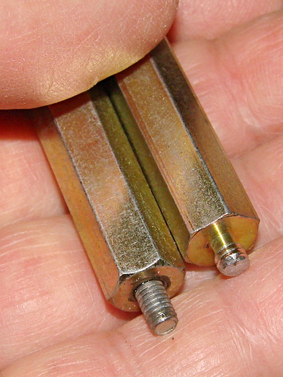
One end had 4-40 tapped holes that I drilled out to clear the VESA mount’s M4x0.7 screws; I sawed the heads off four M4 screws and epoxied them in place. The other end had 8-32 studs that I cut down to fit inside the Q150’s dished mounting bracket:
VESA Mount – standoffs
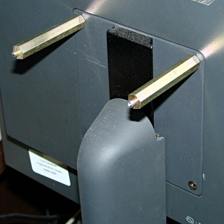
Working around the mount, one standoff at a time, avoided having to lay the monitor flat on the desk:
VESA Mount – standoffs on monitor
A bit of jiggling put the bracket on the standoffs, held in place by the 8-32 nuts:
Lenovo Q150 VESA Mount on monitor
And then the Q150 snapped into place:
Lenovo Q150 – on VESA Mount
It’s captured by a thumbscrew in the bottom left corner (visible in the previous photo), so it can’t fall out.
Took longer to take the pix and write this up than to finish the project… probably because there wasn’t a trace of CNC in sight.
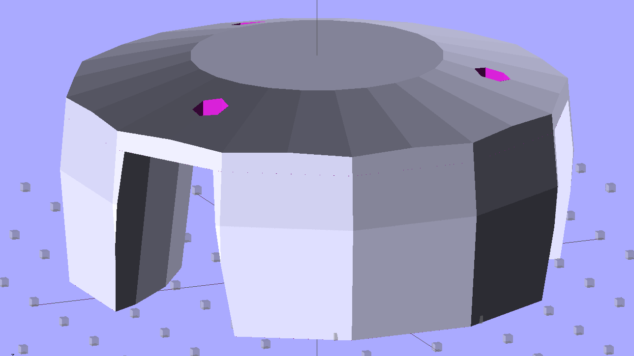
We recently replaced a defunct can opener with an OXO opener that removes can lids without creating razor-sharp edges. Unfortunately, the knob doesn’t agree well with Mary’s hand, so I laid out a prototype doorknob-shaped cap (and also removed all the can lids that confronted her):
OXO Can Opener Knob
It prints in four parts: the flat cover and three pillars, with two filament snippets aligning each pillar. The internal openings of this model do not fit the OXO knob’s lobes correctly; a Dremel sanding drum worked wonderfully well to make it fit. The next version should have much smaller pillar bases with a bit more clearance at the top: measurements from the as-adapted pillars will be in order.
Gluing everything together once again justifies having Too Many Clamps:
OXO Can Opener – gluing knob cover
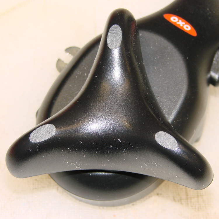
I intended to secure cap to knob with 2-56 screws in those recessed holes and even went so far as to flatten the top of the knob’s lobes in preparation for drilling:
OXO Can Opener – knob flats
However, Dragorn of Kismet gave me a few packets of only slightly outdated Sugru (a great idea that’s far too spendy and short-lived for my shop) that solved the problem:
OXO Can Opener – knob cover with silicone tape
The silicone tape wrap greatly improves the griptitude.
Early returns indicate this works reasonably well, but the top should be more rounded and tapered. It goes without saying that black filament would be much less ugly…
The OpenSCAD source code, with the caveat that the as-printed knob won’t fit without considerable abrasive adjustment:
// OXO Softworks Can Opener
//  Enlarged & rounded knob
// Ed Nisley KE4ZNU December 2012

include </mnt/bulkdata/Project Files/Thing-O-Matic/MCAD/units.scad>
include </mnt/bulkdata/Project Files/Thing-O-Matic/Useful Sizes.scad>

// Layout options

Layout = "Cap";
                    // Overall layout: Build1 Build2
                    // Parts: Cap Knob

//- Extrusion parameters must match reality!
//  Print with +1 shells and 3 solid layers

ThreadThick = 0.25;
ThreadWidth = 2.0 * ThreadThick;

HoleWindage = 0.2;

function IntegerMultiple(Size,Unit) = Unit * ceil(Size / Unit);

Protrusion = 0.1;           // make holes end cleanly

//----------------------
// Dimensions

TriLobeRad = 37.5;					// radius: center to end of lobe
TriLobeOD = 2*TriLobeRad;
TriLobePeakRad = 23.0;				// radius: center to peak height
TriLobeHeight = 22.5;

WingArcRad2 = 48;					// Arc between knob lobes, top
WingArcRad1 = WingArcRad2 - 5;		//
WingArcOffset = 14.0;				// Knob center to arc2 radius

KnobOD1 = 70;						// maximum dia without chamfer
KnobOD2 = 65;						// top dia

KnobSides = 3*4;					// maintain 3-side symmetry

DomeHeight = 8;						// dome shape above lobes

KnobHeight = DomeHeight + TriLobeHeight;

DomeOD = KnobOD2 + (KnobOD1 - KnobOD2)*(DomeHeight/KnobHeight);

DomeArcRad = (pow(KnobHeight,2) + pow(DomeOD,2)/4) / (2*DomeHeight);

ScrewDia = Tap2_56;
ScrewHeadDia = Head2_56;
ScrewBase = 0.6*DomeHeight - Head2_56Thick;

AlignPinDia = 3.0;
AlignPinCircleRad = 0.55*(WingArcOffset + KnobOD2/2);
AlignPinDepth = 3.0;

//----------------------
// Useful routines

module PolyCyl(Dia,Height,ForceSides=0) {           // based on nophead's polyholes

Sides = (ForceSides != 0) ? ForceSides : (ceil(Dia) + 2);

FixDia = Dia / cos(180/Sides);

cylinder(r=(FixDia + HoleWindage)/2,
         h=Height,
         $fn=Sides);
}

module ShowPegGrid(Space = 10.0,Size = 1.0) {

    Range = floor(50 / Space);

    for (x=[-Range:Range])
        for (y=[-Range:Range])
            translate([x*Space,y*Space,Size/2])
            %cube(Size,center=true);

}

//-------------------
// Component parts

module TriKnob() {
	intersection() {
		difference(convexity=3) {
			translate([0,0,-Protrusion])
				cylinder(r=TriLobeRad,h=(TriLobeHeight + 2*Protrusion));
			for (i=[-1:1])
				rotate(i*120)
					translate([(WingArcOffset + WingArcRad2),0,-TriLobeHeight/2])
						cylinder(r1=WingArcRad1,r2=WingArcRad2,h=2*TriLobeHeight);
		}
		translate([0,0,TriLobeHeight/2])
		cube([2*KnobOD1,2*KnobOD2,TriLobeHeight],center=true);
	}
}

module KnobCap() {
	difference() {
		intersection() {
			translate([0,0,(KnobHeight-DomeArcRad)])
				rotate(180/KnobSides)
					sphere(r=DomeArcRad,$fa=180/KnobSides);
			difference(convexity=4) {
				rotate(180/KnobSides)
					cylinder(r1=KnobOD1/2,r2=KnobOD2/2,h=KnobHeight,$fn=KnobSides);
				TriKnob();
			}
			rotate(180/KnobSides)
				cylinder(r1=KnobOD2/2,r2=KnobOD1/2,h=KnobHeight,$fn=KnobSides);
		}
		for (i=[-1:1])
			rotate(i*120) {
				translate([-TriLobePeakRad,0,0]) {
					PolyCyl(ScrewDia,KnobHeight);
					translate([0,0,TriLobeHeight + ScrewBase])
						PolyCyl(ScrewHeadDia,KnobHeight);
				}
			}
		for (i=[-1:1]) for (j=[-1,1])
			rotate(i*120 + j*(270/KnobSides))
				translate([AlignPinCircleRad,0,(TriLobeHeight - AlignPinDepth - Protrusion)])
					PolyCyl(AlignPinDia,2*(AlignPinDepth + Protrusion));
	}
}

//----------------------
// Build it!

ShowPegGrid();

if (Layout == "Cap")
	difference() {
		KnobCap();
		cylinder(r=KnobOD1,h=Protrusion/2,center=true);
	}

if (Layout == "Knob")
	TriKnob();

if (Layout == "Build1")
	translate([0,0,-TriLobeHeight])
		difference() {
			KnobCap();
			translate([0,0,(TriLobeHeight - Protrusion)/2])
				cube([2*KnobOD1,2*KnobOD2,TriLobeHeight+Protrusion],center=true);
		}

if (Layout == "Build2")
	translate([0,0,TriLobeHeight])
		rotate([180,0,0])
			difference() {
				KnobCap();
				translate([0,0,(TriLobeHeight + TriLobeHeight/2)])
					cube([2*KnobOD1,2*KnobOD2,TriLobeHeight],center=true);
			}
Our Larval Engineer received a logic probe / pulser set for Christmas:
RSR Logic Probe Pulser Set – with formed covers
They’re the low-cost RSR-611 and -620 from the usual eBay vendor, not my ancient HP10525/10526 set, but they should suffice. Perhaps nobody uses logic probes these days, what with most of the parts being too small for even a needle tip, but …
Anyhow, they didn’t have caps over the sharp probe tips, so I rummaged around until I found the stash of cigar tubes (some of which went into that air flow straightener) that were about the right size. I thought about 3D printing an adapter between tubes and probes:
RSR Probe Cap Adapter – solid model
It’s actually a subtractive kind of thing, with a model of the probe tip subtracted from a suitable cylindrical object:
RSR Logic Probe – solid model
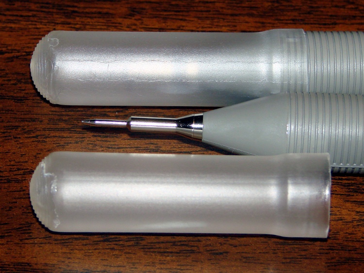
But then I realized the tubes were thermoplastic, held each one over a stove burner until the open end went transparent and droopy, rammed it down over the probe tip, and trimmed off the ragged edge. Worked fine, fits securely, and even looks pretty good:
RSR Covers – detail
I’ll never print the adapters, but maybe one of us will tweak the model to do something else…
The OpenSCAD source code:
// RSR Logic Probe / Pulser Cap
// Ed Nisley KE4ZNU December 2012

// Adapts cigar tube to probe body

// Layout options

Layout = "Build";
                    // Overall layout: Show Build
			// Parts: Probe

//- Extrusion parameters must match reality!
//  Print with +1 shells and 3 solid layers

ThreadThick = 0.25;
ThreadWidth = 2.0 * ThreadThick;

HoleWindage = 0.2;

function IntegerMultiple(Size,Unit) = Unit * ceil(Size / Unit);

Protrusion = 0.1;           // make holes end cleanly

//----------------------
// Dimensions

ProbeDia = 18.0;				// dia of main body
ProbeTipDia = 6.8;				// dia at end of plastic cone
ProbeTipLen = 30.0;				// length of metal ferrule + tip
ProbeConeLen = 17.5;			// cone taper length

TubeOD = 17.25;
TubeWall = 0.50;
TubeID = TubeOD - 2*TubeWall;

TubeLen = 15;					// slip fit over tube body

BodyLen = 20;					// slip fit over probe body

WallThick = 3.5*ThreadWidth;		// basic adapter wall thickness

AdapterLen = TubeLen + BodyLen;
AdapterOD = ProbeDia + 2*WallThick;
AdapterSides = 4*4;

//----------------------
// Useful routines

module PolyCyl(Dia,Height,ForceSides=0) {           // based on nophead's polyholes

Sides = (ForceSides != 0) ? ForceSides : (ceil(Dia) + 2);

FixDia = Dia / cos(180/Sides);

cylinder(r=(FixDia + HoleWindage)/2,
         h=Height,
         $fn=Sides);
}

module ShowPegGrid(Space = 10.0,Size = 1.0) {

    Range = floor(50 / Space);

    for (x=[-Range:Range])
        for (y=[-Range:Range])
            translate([x*Space,y*Space,Size/2])
            %cube(Size,center=true);

}

module Probe() {
	union() {
		cylinder(r=((ProbeDia + HoleWindage)/2),
				 h=(BodyLen + 1.2*Protrusion),$fn=2*AdapterSides);
		translate([0,0,(BodyLen + Protrusion)])
			cylinder(r1=(ProbeDia + HoleWindage)/2,
					 r2=ProbeTipDia/2,
					 h=ProbeConeLen,$fn=2*AdapterSides);
		cylinder(r=ProbeTipDia/2,h=(BodyLen + ProbeConeLen + ProbeTipLen),$fn=2*AdapterSides);
	}
}

module ProbeSleeve() {

	difference() {
		cylinder(r=AdapterOD/2,h=AdapterLen);
		translate([0,0,-Protrusion])
			Probe();
		PolyCyl((TubeOD + HoleWindage),(AdapterLen + Protrusion),2*AdapterSides);
	}
}

//----------------------
// Build it!

ShowPegGrid();

if (Layout == "Show")
    ProbeSleeve();

if (Layout == "Build")
    translate([0,0,AdapterLen])
		rotate([180,0,0])
			ProbeSleeve();

if (Layout == "Probe")
	Probe();
While wiring up the LED stress tester, I realized I should abuse a string of amber LEDs along with the three red strings. Herewith, four amber LEDs from the top of their bag, with LED 5 = LED 1 retested:
Amber LEDs – 100 mA
Apart from being an outlier, that red trace seems much prettier than the others, doesn’t it?
The Bash / Gnuplot routine that produced the graph has a few tweaks:
#!/bin/sh
numLEDs=4
#-- overhead
export GDFONTPATH="/usr/share/fonts/truetype/"
base="${1%.*}"
echo Base name: ${base}
ofile=${base}.png
echo Input file: $1
echo Output file: ${ofile}
#-- do it
gnuplot << EOF
#set term x11
set term png font "arialbd.ttf" 18 size 950,600
set output "${ofile}"
set title "${base}"
set key noautotitles
unset mouse
set bmargin 4
set grid xtics ytics
set xlabel "Forward Voltage - V"
set format x "%6.3f"
set xrange [1.8:2.2]
#set xtics 0,5
set mxtics 2
#set logscale y
#set ytics nomirror autofreq
set ylabel "Current - mA"
set format y "%4.0f"
set yrange [0:120]
set mytics 2
#set y2label "right side variable"
#set y2tics nomirror autofreq 2
#set format y2 "%3.0f"
#set y2range [0:200]
#set y2tics 32
#set rmargin 9
set datafile separator "\t"
set label 1 "LED 1 = LED $((numLEDs + 1))" at 2.100,110 right font "arialbd,18"
set arrow from 2.100,110 to 2.105,103 lt 1 lw 2 lc 0
plot	\
    "$1" index 0:$((numLEDs - 1)) using (\$5/1000):(\$2/1000):(column(-2)) with linespoints lw 2 lc variable,\
    "$1" index $numLEDs using (\$5/1000):(\$2/1000) with linespoints lw 2 lc 0
EOF
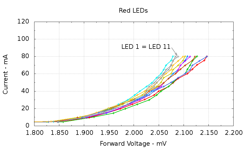
Running ten random red LEDs (taken from the bag of 100 sent halfway around the planet) through the LED Curver Tracer produces this plot:
Red LEDs – 80 mA
The two gray traces both come from LED 1 to verify that the process produces the same answer for the same LED. It does, pretty much.
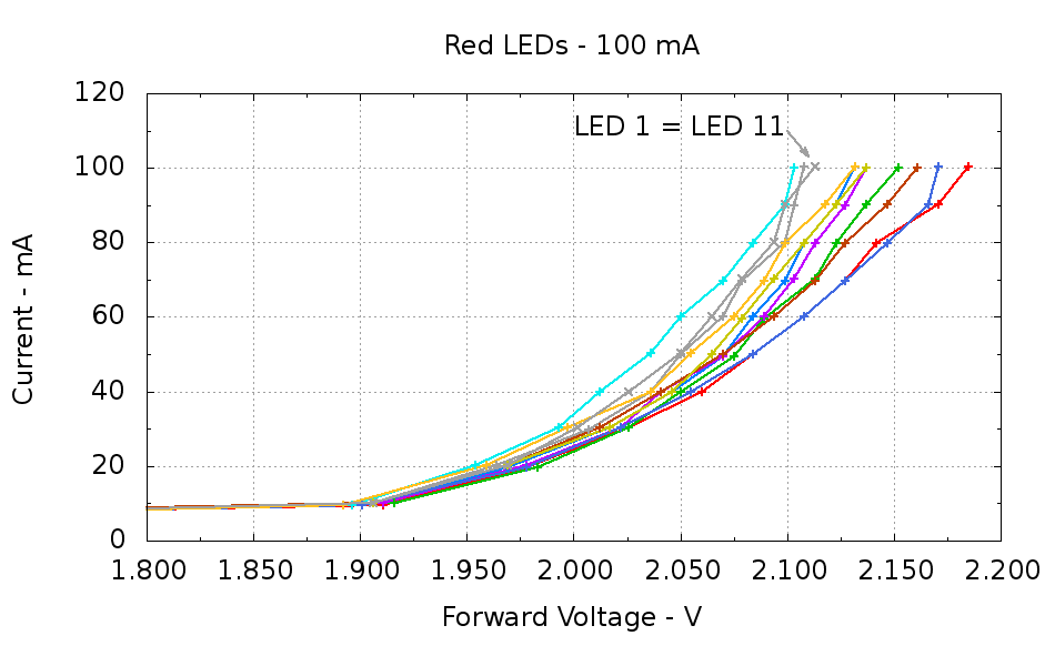
Repeating that with the same LEDs in the same order, but stepping 10 mA up to 100 mA produces a similar plot:
Red LEDs – 100 mA
The voltage quantization comes from the Arduino’s 5 mV ADC resolution (the readings are averaged, but there’s actually not much noise) and the current quantization comes from the step value in the measurement loop (5 mA in the first plot, 10 mA in the second). Seeing the LEDs line up mostly the same way at 80 mA in both graphs is comforting, as it suggests the measurement results aren’t completely random numbers.
Putting three red LEDs in series could produce a total forward drop anywhere between 6.309 V (3*2.103) and 6.555 V (3*2.185), a difference of nigh onto a quarter volt, if you assume this group spans the entire range of voltages and the whole collection has many duplicate values and you’re remarkably unlucky while picking LEDs. For this particular set, however, summing three successive groups of three produces 6.445, 6.372, and 6.469 V, for a spread of just under 100 mV. That suggests it’s probably not worthwhile to select LEDs for forward voltage within each series group of three, although matching parallel LEDs makes a lot of sense. I have no confidence the values will remain stable over power-on hours / thermal cycling / current stress.
The capacity plot for the Wouxun KG-UV3D lithium battery packs shows that there’s not a lot of capacity left after 7.0 V, so shutting down or scaling back to lower current wouldn’t be a major loss. However, it’s not clear a fixed resistor will do a sufficient job of current limiting with 6.5 V forward voltage across the LED string:
At 7.5 V, 100 mA calls for 10 Ω (drop 1 V at 100 mA)
At 8.2 V, 10 Ω produces 170 mA (1.7 V across 10 Ω)
At 7.0 V, 10 Ω produces 50 mA (0.5 V across 10 Ω)
Obviously, 170 mA is way too much, even by my lax standards.
A 100 mV variation in forward voltage between stacks, each with a 10 Ω resistor, translates into about 10 mA difference in current. This may actually call for current sensors and direct current control, although using a sensor per string, seems excessive. Low dropout regulators in current-source mode might suffice, but that still seems messy.
The test rig will run from a hard 7.5 V supply, which means I can use fixed resistors and be done with it.
The raw data behind those graphs, with LED 1 and LED 11 being the same LED:
#!/bin/sh
#-- overhead
export GDFONTPATH="/usr/share/fonts/truetype/"
base="${1%.*}"
echo Base name: ${base}
ofile=${base}.png
echo Input file: $1
echo Output file: ${ofile}
#-- do it
gnuplot << EOF
#set term x11
set term png font "arialbd.ttf" 18 size 950,600
set output "${ofile}"
set title "${base}"
set key noautotitles
unset mouse
set bmargin 4
set grid xtics ytics
set xlabel "Forward Voltage - V"
set format x "%6.3f"
set xrange [1.8:2.2]
#set xtics 0,5
set mxtics 2
#set logscale y
#set ytics nomirror autofreq
set ylabel "Current - mA"
set format y "%4.0f"
set yrange [0:120]
set mytics 2
#set y2label "right side variable"
#set y2tics nomirror autofreq 2
#set format y2 "%3.0f"
#set y2range [0:200]
#set y2tics 32
#set rmargin 9
set datafile separator "\t"
set label 1 "LED 1 = LED 11" at 2.100,110 right font "arialbd,18"
set arrow from 2.100,110 to 2.110,103 lt 1 lw 2 lc 0
plot    \
"$1" index 0:9 using (\$5/1000):(\$2/1000):(column(-2)) with linespoints lw 2 lc variable,\
"$1" index 10 using (\$5/1000):(\$2/1000) with linespoints lw 2 lc 0
EOF
And the Arduino source code, which bears a remarkable resemblance to the original firmware:
// LED Curve Tracer
// Ed Nisley - KE4ANU - December 2012

#include <stdio.h>

//----------
// Pin assignments

const byte PIN_READ_LEDSUPPLY = 0;    // AI - LED supply voltage        blue
const byte PIN_READ_VDRAIN = 1;        // AI - drain voltage            red
const byte PIN_READ_VSOURCE = 2;    // AI - source voltage            orange
const byte PIN_READ_VGATE = 3;        // AI - VGS after filtering        violet

const byte PIN_SET_VGATE = 11;        // PWM - gate voltage            brown

const byte PIN_BUTTON1 = 8;            // DI - button to start tests    green
const byte PIN_BUTTON2 = 7;            // DI - button for options        yellow

const byte PIN_HEARTBEAT = 13;        // DO - Arduino LED
const byte PIN_SYNC = 2;            // DO - scope sync output

//----------
// Constants

const int MaxCurrent = 100;                // maximum LED current - mA
const int ISTEP = 10;                    // LED current increment

const float Vcc = 4.930;                // Arduino supply -- must be measured!

const float RSense = 10.500;            // current sense resistor

const float ITolerance = 0.0005;        // current setpoint tolerance

const float VGStep = 0.019;                // increment/decrement VGate = 5 V / 256

const byte PWM_Settle = 5;                // PWM settling time ms

#define TCCRxB 0x01                        // Timer prescaler = 1:1 for 32 kHz PWM

#define MK_UL(fl,sc) ((unsigned long)((fl)*(sc)))
#define MK_U(fl,sc) ((unsigned int)((fl)*(sc)))

//----------
// Globals

float AVRef1V1;                    // 1.1 V bandgap reference - calculated from Vcc

float VccLED;                    // LED high-side supply

float VDrain;                    // MOSFET terminal voltages
float VSource;
float VGate;

unsigned int TestNum = 1;

long unsigned long MillisNow;

//-- Read AI channel
//      averages several readings to improve noise performance
//        returns value in mV assuming VCC ref voltage

#define NUM_T_SAMPLES    10

float ReadAI(byte PinNum) {

word RawAverage;

digitalWrite(PIN_SYNC,HIGH);                // scope sync

RawAverage = analogRead(PinNum);            // prime the averaging pump

for (int i=2; i <= NUM_T_SAMPLES; i++) {
RawAverage += (word)analogRead(PinNum);
}

digitalWrite(PIN_SYNC,LOW);

RawAverage /= NUM_T_SAMPLES;

return Vcc * (float)RawAverage / 1024.0;

}

//-- Set PWM output

void SetPWMVoltage(byte PinNum,float PWMVolt) {

byte PWM;

PWM = (byte)(PWMVolt / Vcc * 255.0);

analogWrite(PinNum,PWM);
delay(PWM_Settle);

}

//-- Set VGS to produce desired LED current
//        bails out if VDS drops below a sensible value

void SetLEDCurrent(float ITarget) {

float ISense;                // measured current
float VGateSet;            // output voltage setpoint
float IError;                // (actual - desired) current

VGate = ReadAI(PIN_READ_VGATE);                    // get gate voltage
VGateSet = VGate;                                    //  because input may not match output

do {

VSource = ReadAI(PIN_READ_VSOURCE);
ISense = VSource / RSense;                        // get LED current

//    printf("\r\nITarget: %lu mA",MK_UL(ITarget,1000.0));
IError = ISense - ITarget;

//    printf("\r\nISense: %d mA VGateSet: %d mV VGate %d IError %d mA",
//           MK_U(ISense,1000.0),
//           MK_U(VGateSet,1000.0),
//           MK_U(VGate,1000.0),
//           MK_U(IError,1000.0));

if (IError < -ITolerance) {
VGateSet += VGStep;
//      Serial.print('+');
}
else if (IError > ITolerance) {
VGateSet -= VGStep;
//      Serial.print('-');
}

VGateSet = constrain(VGateSet,0.0,Vcc);
SetPWMVoltage(PIN_SET_VGATE,VGateSet);

VDrain = ReadAI(PIN_READ_VDRAIN);        // sample these for the main loop
VGate = ReadAI(PIN_READ_VGATE);
VccLED = ReadAI(PIN_READ_LEDSUPPLY);

if ((VDrain - VSource) < 0.020) {            // bail if VDS gets too low
printf("# VDS=%d too low, bailing\r\n",MK_U(VDrain - VSource,1000.0));
break;
}

} while (abs(IError) > ITolerance);

//    Serial.println(" Done");
}

//-- compute actual 1.1 V bandgap reference based on known VCC = AVcc (more or less)
//        adapted from http://code.google.com/p/tinkerit/wiki/SecretVoltmeter

float ReadBandGap(void) {

word ADCBits;
float VBandGap;

ADMUX = _BV(REFS0) | _BV(MUX3) | _BV(MUX2) | _BV(MUX1);    // select 1.1 V input
delay(2); // Wait for Vref to settle

ADCSRA |= _BV(ADSC);                                        // Convert
while (bit_is_set(ADCSRA,ADSC));

ADCBits = ADCL;
ADCBits |= ADCH<<8;

VBandGap = Vcc * (float)ADCBits / 1024.0;
return VBandGap;
}

//-- Print message, wait for a given button press

void WaitButton(int Button,char *pMsg) {
printf("# %s",pMsg);
while(HIGH == digitalRead(Button)) {
delay(100);
digitalWrite(PIN_HEARTBEAT,!digitalRead(PIN_HEARTBEAT));
}

delay(50);                // wait for bounce to settle
digitalWrite(PIN_HEARTBEAT,LOW);
}

//-- Helper routine for printf()

int s_putc(char c, FILE *t) {
Serial.write(c);
}

//------------------
// Set things up

void setup() {
pinMode(PIN_HEARTBEAT,OUTPUT);
digitalWrite(PIN_HEARTBEAT,LOW);    // show we arrived

pinMode(PIN_SYNC,OUTPUT);
digitalWrite(PIN_SYNC,LOW);        // show we arrived

TCCR1B = TCCRxB;                    // set frequency for PWM 9 & 10
TCCR2B = TCCRxB;                    // set frequency for PWM 3 & 11

pinMode(PIN_SET_VGATE,OUTPUT);
analogWrite(PIN_SET_VGATE,0);        // force gate voltage = 0

pinMode(PIN_BUTTON1,INPUT_PULLUP);    // use internal pullup for buttons
pinMode(PIN_BUTTON2,INPUT_PULLUP);

Serial.begin(9600);
fdevopen(&s_putc,0);                // set up serial output for printf()

printf("# LED Curve Tracer\r\n# Ed Nisley - KE4ZNU - December 2012\r\n");

VccLED = ReadAI(PIN_READ_LEDSUPPLY);
printf("# VCC at LED: %d mV\r\n",MK_U(VccLED,1000.0));

AVRef1V1 = ReadBandGap();            // compute actual bandgap reference voltage
printf("# Bandgap reference voltage: %lu mV\r\n",MK_UL(AVRef1V1,1000.0));

}

//------------------
// Run the test loop

void loop() {

Serial.println('\n');                        // blank line for Gnuplot indexing

WaitButton(PIN_BUTTON1,"Insert LED, press button 1 to start...\r\n");
printf("# INOM\tILED\tVccLED\tVD\tVLED\tVG\tVS\tVGS\tVDS\t<--- LED %d\r\n",TestNum++);
digitalWrite(PIN_HEARTBEAT,LOW);

for (int ILED=0; ILED <= MaxCurrent; ILED+=ISTEP) {
SetLEDCurrent(((float)ILED)/1000.0);
printf("%d\t%lu\t%d\t%d\t%d\t%d\t%d\t%d\t%d\r\n",
ILED,
MK_UL(VSource / RSense,1.0e6),
MK_U(VccLED,1000.0),
MK_U(VDrain,1000.0),
MK_U(VccLED - VDrain,1000.0),
MK_U(VGate,1000.0),
MK_U(VSource,1000.0),
MK_U(VGate - VSource,1000),
MK_U(VDrain - VSource,1000.0)
);
}

SetPWMVoltage(PIN_SET_VGATE,0.0);

}