Ed Nisley's Blog: Shop notes, electronics, firmware, machinery, 3D printing, laser cuttery, and curiosities. Contents: 100% human thinking, 0% AI slop.
Tag: Improvements
Making the world a better place, one piece at a time
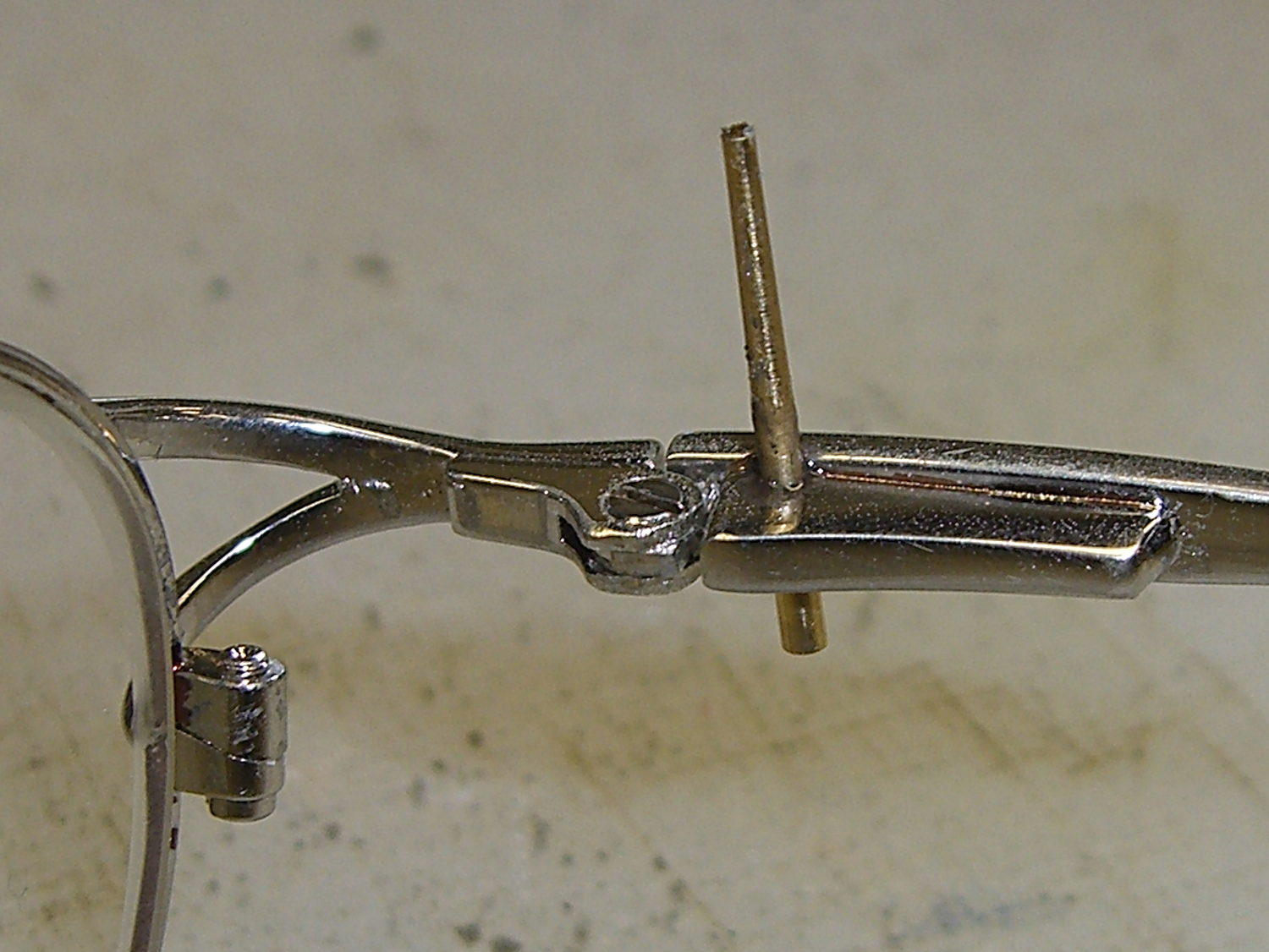
Unfortunately, the smooth interior of the temple spring pocket and the smooth exterior of the hinge plate didn’t provide enough mechanical lock for the epoxy; the pieces pulled apart after a week.
So I put a stake in its heart:
Eyeglass temple – tapered pin
That’s a tapered brass pin from the Box o’ Clock Parts, buttered up with a dab of epoxy, then shoved firmly into a 41 mil (#59) hole drilled through the pocket and the edge of the hinge plate.
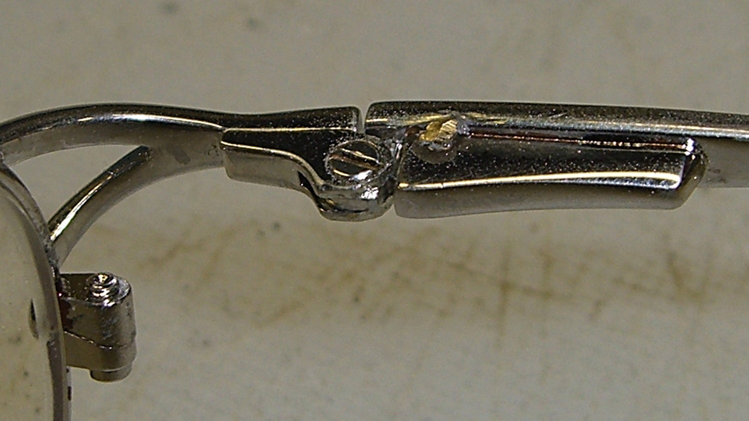
Fast-forward overnight, apply a Dremel grinding bit, and it looks passable:
I recently exhumed an Iomega 500 GB Home Network Hard Drive (model MDHD-500-N) from the Big Box o’ Drives, with the intent of dumping video files from the Sony HDR-AS30 helmet camera thereupon.
Remember Iomega of ZIP Drive fame? Seems EMC Borged ’em a while back, collided with Lenovo, discarded all the old hardware support, and that’s the end of that story.
Exhuming the setup password from my backup stash wasn’t worth the effort, so I experimentally determined that holding the Reset switch closed while turning the drive on blows away the existing configuration. It woke up, asked for an IP address, got 192.168.1.52 from the DHCP server (you can find that by checking the router’s tables), and popped up the administration console at 192.168.1.52:80 as you’d expect.
The userid will always be admin, but you can change the password from admin to whatever you like; you may safely assume I have done somewhat better than what you see below.
Twiddling the configuration through the IOmega web-based console:
Device name: IOMEGA-500MB (for lack of anything more creative)
Group name: WHATSMYNET
Password: not-admin
Drag the date/time into the current millennium
Time Zone: GMT-5:00
Time Server: 0.us.pool.ntp.org
Static IP: 192.168.1.10 (suitable for my network)
Gateway & DNS as appropriate
Windows File Sharing enabled for the PUBLIC directory
FTP turned off
Sleep time: 10 minutes
Changing either the IP address or the password requires logging in again, of course.
I reformatted the drive, just to be sure.
Then, after a bit of Googling to remember how all this works…
A line in /etc/hosts (left over from the last time I did this) gives the new static IP address:
192.168.1.10 nasty
Install the cifs-utils package to enable mounting the drive.
Create a mount point:
sudo mkdir /mnt/video
Create a file (/root/.nas-id) holding the super-secret credentials used to gain access to the drive:
domain=WHATSMYNET
username=ed
password=not-admin
Then restrict the file to the eyes of the root user:
sudo chmod 700 /root/.nas-id
It’s not clear that the username or domain really make any difference in this situation, but there they are.
Define where and how to mount the network drive with a new line at the bottom of /etc/fstab, which refers to the aforementioned super-secret credentials file:
Mounting it with my userid gives the shared directories & files proper permissions for me (and nobody else, not that anybody else around here cares).
So the manual mounting process looks like this:
sudo mount /mnt/video
Adding the user mount option would eliminate the sudo, but manual mounting won’t be necessary after a normal boot when the automagic startup script does the deed.
The drive must have the noauto attribute to prevent the upstart Pachinko machine from trying to mount the network drives before the network comes up. Actually mounting the drive at the proper time requires an additional line in /etc/init/local.conf:
description "Stuff that should be in /etc/rc.local"
author "Ed Nisley - KE4ZNU"

start on (local-filesystems and net-device-up IFACE=em1)
stop on shutdown

emits nfs-mounted

script

logger Starting local init...

logger Mounting NFS (and CIFS) filesystems
mount /mnt/bulkdata
mount /mnt/userfiles
mount /mnt/diskimages
mount /mnt/music
mount /mnt/video
initctl emit nfs-mounted
logger Ending local init

end script
The reason the drive wound up in the Big Box o’ Hard Drives was its lethargic transfer speed; copying a 4 GB video file from either the MicroSDXC card (via an SD adapter) or the previous 750 GB USB-attached hard drive to the IOmega NAS trundles along at a little over 6 MB/s. The camera stores 25 Mb/s = 3 MB/s of data in 1080p @ 60 fps, so figure 1/2 hour of copying per hour of riding. The USB drive can write data from the aforementioned MicroSDXC card at 18 MB/s, so the card and USB interface aren’t the limiting factors.
I’m not (generally) in a big hurry while copying files from the camera’s SD card, because that’s now automated:
#!/bin/sh
thisdate=$(date --rfc-3339=date)
echo Date is [$thisdate]
# IOmega NASalready mounted as /mnt/video in fstab
mkdir /mnt/video/$thisdate
sudo mount -o uid=ed /dev/sdb1 /mnt/part
rsync -ahu --progress /mnt/part/MP_ROOT/100ANV01/ /mnt/video/$thisdate
if [ $? -eq 0 ] ; then
 rm /mnt/part/MP_ROOT/100ANV01/*
 sudo umount /mnt/part
fi
I’ve been discarding the oldest month of videos as the USB hard drive fills up, which will happen a bit more often than before: the drive’s 466 GB can hold barely 35 hours of ride video.
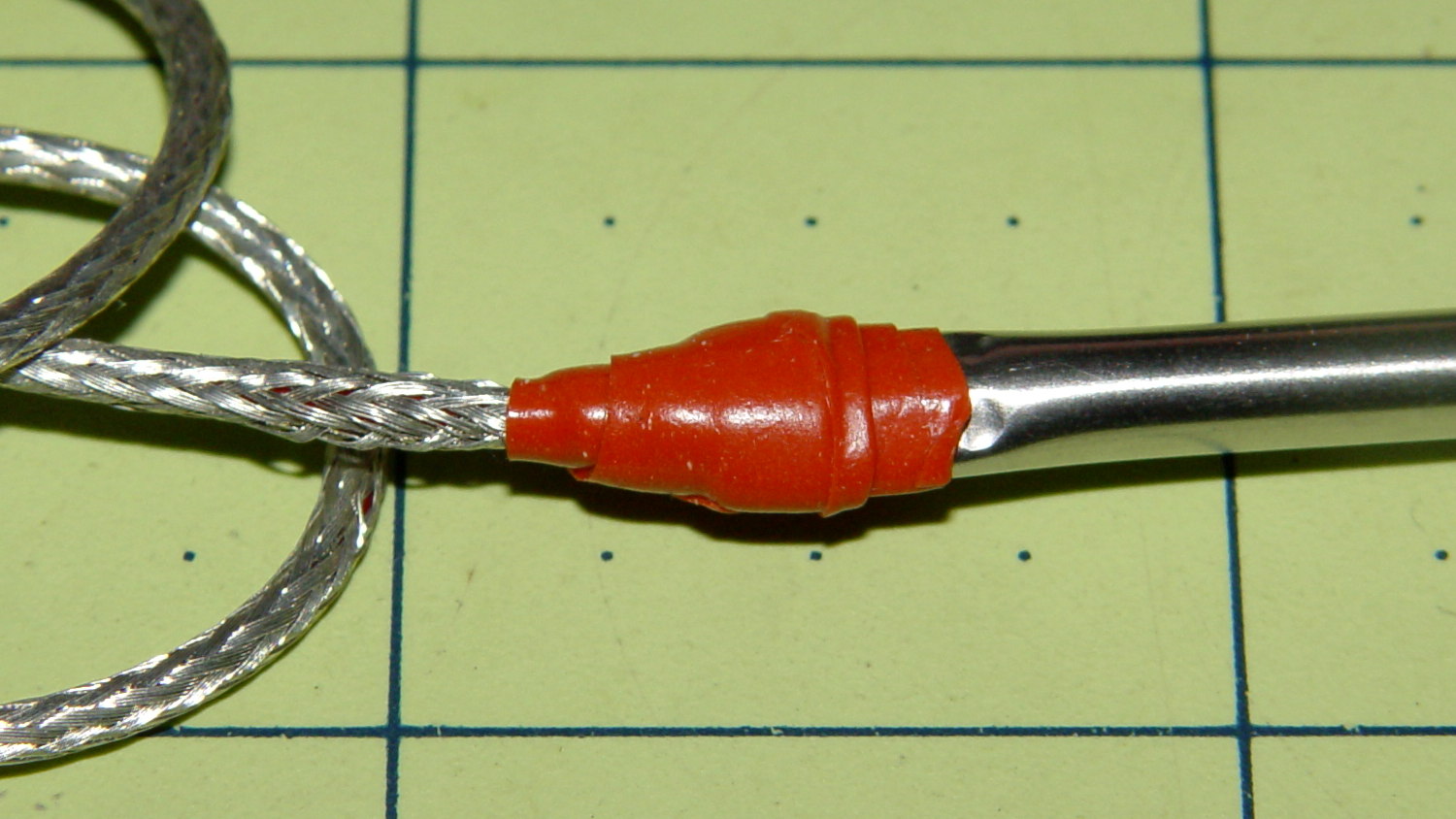
The replacement probe has a woven metal jacket that’s allegedly more rugged than the original plastic, but I think the main difference comes from the additional strain relief at the end of the probe:
Kitchen thermometer – new probe
That still looks abrupt to me, so I wrapped a silicone tape snippet around the joint:
Kitchen thermometer – new strain relief
Probably not food-safe, definitely butt-ugly, but I don’t want to replace the probe again for a long time.
FWIW, although the probe description says it’s compatible with Taylor 1970N thermometers and doesn’t mention the 1478 we have, the 2.5 mm plug fits (no suprise there) and the display shows appropriate temperatures; it seems no less accurate than the original probe.
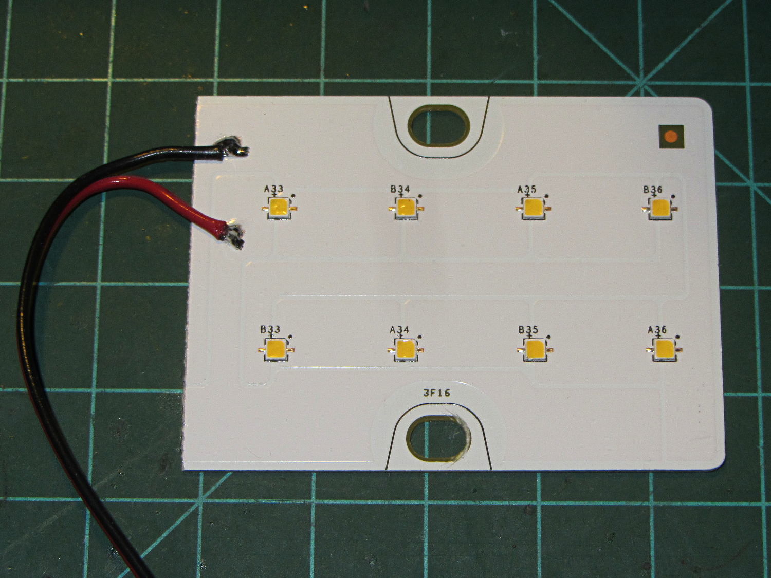
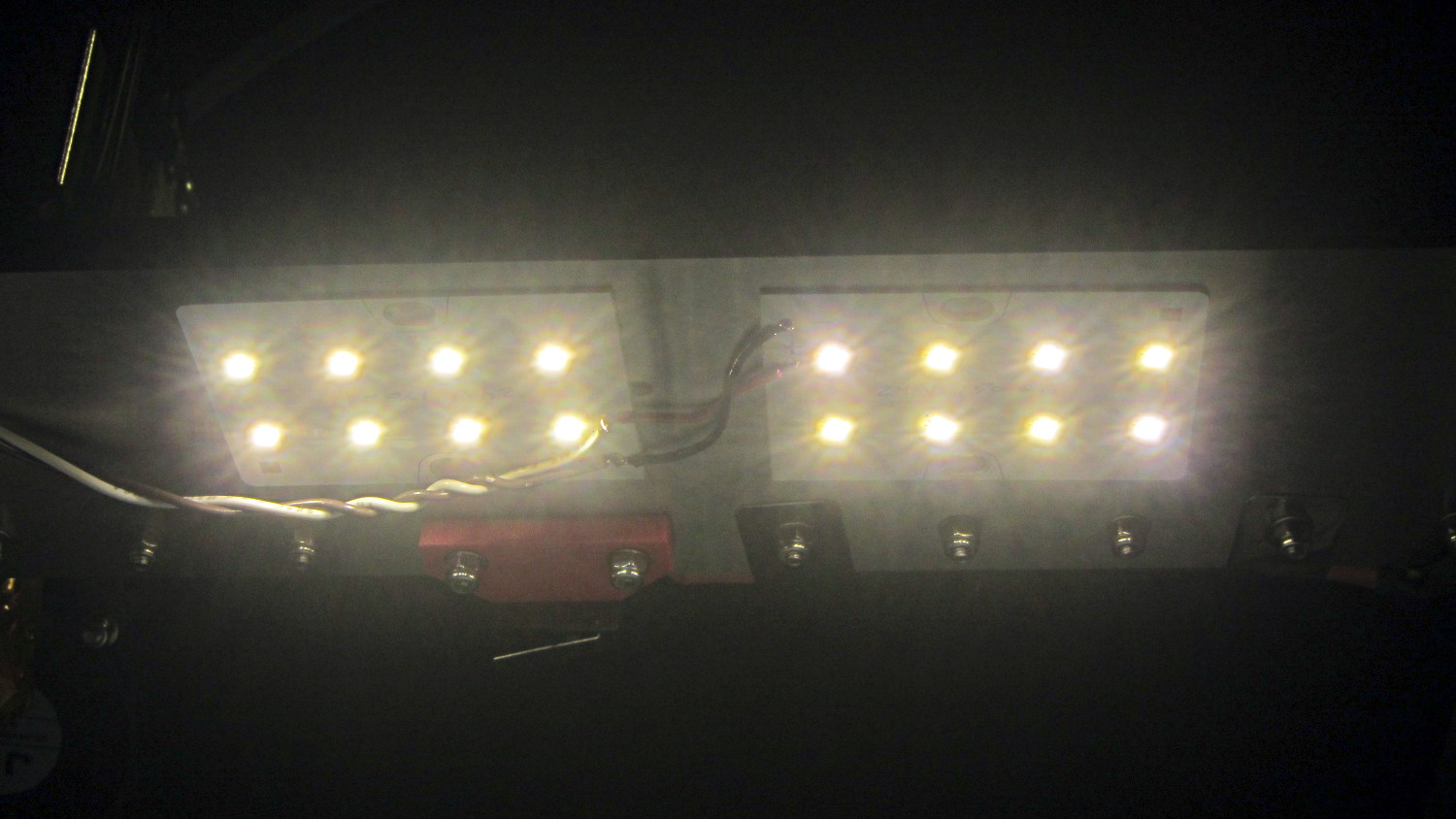
A surplus haul of 24 V / 150 mA white LED panels arrived:
LED Panel – 24 V 150 mA
I wired a pair to a 24 V wall wart and stuck them under the M2’s bridge supporting the X stage:
LED Panel – on M2 Gantry
I thought about epoxying them in place to get better heatsinking to the metal bridge. The ever-trustworthy description said the big copper baseplate meant the panels didn’t need any heatsinking, so I used tapeless sticky and will hope for the best. Should the sticky give out, then I’ll use epoxy.
They’re much better than the previous white LED strip, although it’s tough to tell in the pictures. The chain mail armor appears under the new lights; some older pictures will creep in from time to time.
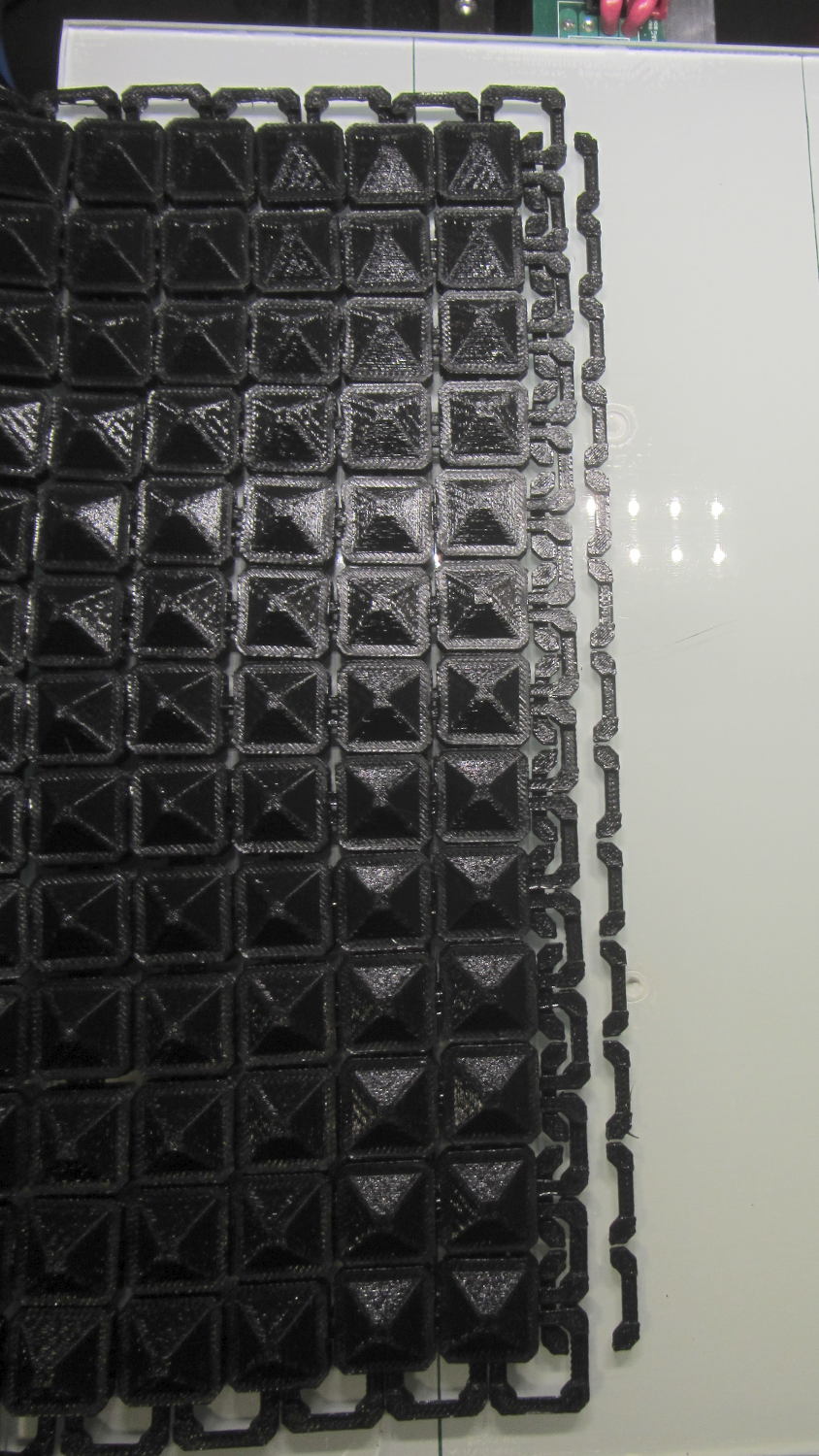
Another nine hours of printing produced a second 9×13 link chain mail armor sheet that simply begged to be joined with the first. Snipping a connecting link on one sheet and attempting to thread it through the armor button on the other didn’t work nearly as well as I expected, because the pillars on the open links don’t quite pass through the slot in the side of the armor button links:
Chain Mail Armor – 4 sided
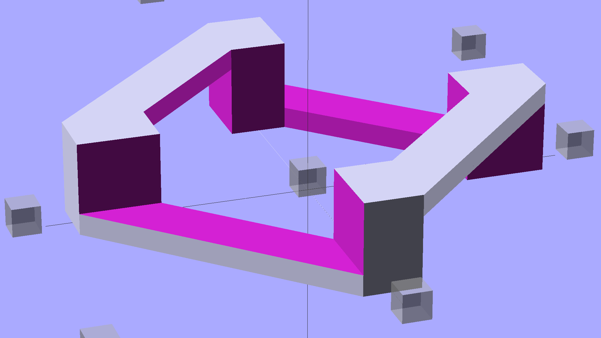
So I summoned joiner links from the digital deep:
Chain Mail Armor – Sheet Joiners
Those are standard armor button links, split at the cross bar level, then laid out along the Y axis. The cap bridges across the link just as it does on the chain mail sheets, so, when they’re glued back together, the result should be exactly like a solid link. There’s no room for alignment pins and, frankly, I wouldn’t fiddle with two dozen filament snippets anyway.
The OpenSCAD code below produces joiners that work for the square arrangement, not the diamond, but that’s in the nature of fine tuning.
When I saw them pasted to the platform, just like the model:
Chain Mail Armor – joiners on platform
It occurred to me that I could pop the caps off, then lay the sheets in position, aligned on the underlying joiner half-links. Here’s the first sheet over the left set of bars:
Chain Mail Armor – sheet and joiners on platform
Then glue the armor caps in place:
Chain Mail Armor – joiner with solvent glue
Four dots of IPS #4 solvent glue, dispensed from a fine copper tube serving as a pipette, wet the four pillars of the joiner’s two bottom bars. I dotted each pillar to begin softening the PLA, paused for a breath, wet them again to leave enough solvent to bite into the bottom of the armor cap, pressed the cap in place, tweaked the alignment with tweezers, then pressed downward for maybe five seconds. Although the joiner link has no inherent alignment features, there’s also not much room to slide around and it worked surprisingly well.
Repeat that trick dozen times and you’re done. The aggravation scales as the square root of the overall sheet size, so it’s not as awful as assembling every single link, but it’s definitely a task for the low-caffeine part of the day.
One bottom bar came loose when I showed the result at the MHVLUG meeting, but the bar reappeared and I glued it again easily enough. I’ve now printed several spare joiners, Just In Case.
The bottom bars aren’t firmly affixed to the platform after it cools and they dislodge fairly easily: that’s how I get larger models off: let everything cool, then simply lift the plastic off. If I were joining sheets on a regular basis, I’d conjure a fixture to hold the sheets and joiner caps in position, probably with the sheets upside down, then glue the bars atop the inverted caps. That could get messy.
Perhaps a special holder to capture the bars in the proper alignment, maybe with pins matching the square openings at the corners, would help?
This is a trial fit before gluing that’s visually indistinguishable from the final product:
Chain Mail Armor – joined sheets on platform
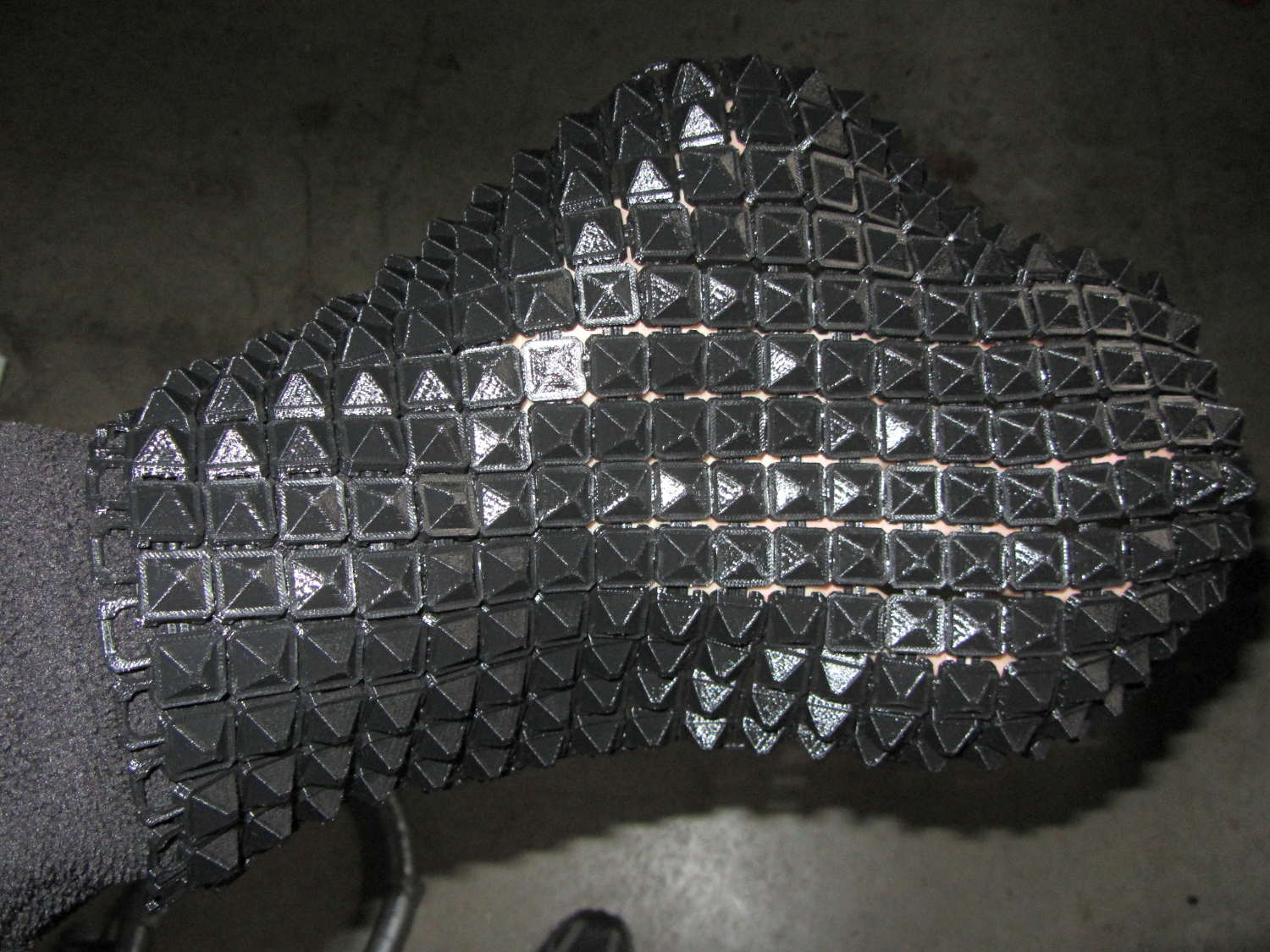
It’s not actually fabric, but it’s sufficiently bendy to cover a hand:
Chain Mail Armor – joined sheet draped on hand
The thing just cries out to be fondled…
There’s a quarter kilogram of plastic in that 8×12 inch = 200×310 mm sheet that almost used up the last of the black PLA spool.
Remember: you must tweak the OpenSCAD code to match your extruder settings, export a suitable STL file, get really compulsive about platform alignment, use hairspray / glue stick to boost platform adhesion, and have no qualms about an all-day print run. You can’t just slice a random STL file produced for a different printer, because the link dimensions come directly from the printer’s capabilities: one size does not fit all.
The OpenSCAD source code [Update: This is the refactored version.]:
// Chain Mail Armor Buttons
// Ed Nisley KE4ZNU - December 2014

Layout = "Build";			// Link Button LB Joiner Joiners Build

//-------
//- Extrusion parameters must match reality!
//  Print with 1 shell and 2+2 solid layers

ThreadThick = 0.20;
ThreadWidth = 0.40;

HoleWindage = 0.2;

Protrusion = 0.1*ThreadThick;			// make holes end cleanly

function IntegerMultiple(Size,Unit) = Unit * ceil(Size / Unit);

//-------
// Dimensions

//- Set maximum sheet size

SheetSizeX = 50;	// 170 for full sheet on M2
SheetSizeY = 60;	// 230

//- Diamond or rectangular sheet?

Diamond = false;					// true = rotate 45 degrees, false = 0 degrees for square

BendAround = "X";					// X or Y = maximum flexibility *around* designated axis

Cap = true;										// true = build bridge layers over links

Armor = true && Cap;							// true = build armor button atop (required) cap
ArmorThick = IntegerMultiple(6,ThreadThick);	// height above cap surface

// Link bar sizes

BarWidth = 6 * ThreadWidth;
BarThick = 4 * ThreadThick;

BarClearance = 5*ThreadThick;		// vertical clearance above & below bars

//-- Compute link sizes from those values

// Absolute minimum base link: bar width + corner angle + build clearance around bars
//  rounded up to multiple of thread width to ensure clean filling
BaseSide = IntegerMultiple((4*BarWidth + 2*BarWidth/sqrt(2) + 3*(2*ThreadWidth)),ThreadWidth);

BaseHeight = 2*BarThick + BarClearance;           // both bars + clearance

echo(str("BaseSide: ",BaseSide," BaseHeight: ",BaseHeight));
echo(str(" Base elements: ",4*BarWidth,", ",2*BarWidth/sqrt(2),", ",3*(2*ThreadWidth)));
echo(str(" total: ",(4*BarWidth + 2*BarWidth/sqrt(2) + 3*(2*ThreadWidth))));

BaseOutDiagonal = BaseSide*sqrt(2) - BarWidth;
BaseInDiagonal = BaseSide*sqrt(2) - 2*(BarWidth/2 + BarWidth*sqrt(2));

echo(str("Outside diagonal: ",BaseOutDiagonal));

//- On-center distance measured along coordinate axis
//   the links are interlaced, so this is half of what you think it should be...

LinkOC = BaseSide/2 + ThreadWidth;

LinkSpacing = Diamond ? (sqrt(2)*LinkOC) : LinkOC;
echo(str("Base spacing: ",LinkSpacing));

//- Compute how many links fit in sheet

MinLinksX = ceil((SheetSizeX - (Diamond ? BaseOutDiagonal : BaseSide)) / LinkSpacing);
MinLinksY = ceil((SheetSizeY - (Diamond ? BaseOutDiagonal : BaseSide)) / LinkSpacing);
echo(str("MinLinks X: ",MinLinksX," Y: ",MinLinksY));

NumLinksX = ((0 == (MinLinksX % 2)) && !Diamond) ? MinLinksX + 1 : MinLinksX;
NumLinksY = ((0 == (MinLinksY % 2) && !Diamond)) ? MinLinksY + 1 : MinLinksY;
echo(str("Links X: ",NumLinksX," Y: ",NumLinksY));

//- Armor button base

CapThick = 4 * ThreadThick;						// at least 3 layers for solid bridging

ButtonHeight = BaseHeight + BarClearance + CapThick;
echo(str("ButtonHeight: ",ButtonHeight));

//- Armor ornament size & shape
//		Fine-tune OD & ID to suit the number of sides...

ArmorSides = 4;
ArmorAngle = true ? 180/ArmorSides : 0;			// true -> rotate half a side for best alignment

TotalHeight = ButtonHeight + ArmorThick;
echo(str("Overall Armor Height: ",TotalHeight));

ArmorOD = 1.1 * BaseSide;						// tune for best base fit
ArmorID = 10 * ThreadWidth;						// make the tip blunt & strong

//-------

module ShowPegGrid(Space = 10.0,Size = 1.0) {

  RangeX = floor(95 / Space);
  RangeY = floor(125 / Space);

	for (x=[-RangeX:RangeX])
	  for (y=[-RangeY:RangeY])
		translate([x*Space,y*Space,Size/2])
		  %cube(Size,center=true);

}

//-------
// Create link with armor button as needed

module Link(Topping = false) {

LinkHeight = (Topping && Cap) ? ButtonHeight : BaseHeight;

render(convexity=3)
	rotate((BendAround == "X") ? 90 : 0)
	rotate(Diamond ? 45 : 0)
		union() {
			difference() {
				translate([0,0,LinkHeight/2])	// outside shape
					intersection() {
						cube([BaseSide,BaseSide,LinkHeight],center=true);
						rotate(45)
							cube([BaseOutDiagonal,BaseOutDiagonal,LinkHeight],center=true);
					}
				translate([0,0,(BaseHeight + BarClearance - Protrusion)/2])
					intersection() {		// inside shape
						cube([(BaseSide - 2*BarWidth),
								(BaseSide - 2*BarWidth),
								(BaseHeight + BarClearance + Protrusion)],
								center=true);
						rotate(45)
							cube([BaseInDiagonal,
									BaseInDiagonal,
									(BaseHeight + BarClearance + Protrusion)],
									center=true);
				}

				translate([0,0,((BarThick + 2*BarClearance)/2 + BarThick)])		// openings for bars
					cube([(BaseSide - 2*BarWidth - 2*BarWidth/sqrt(2)),
						(2*BaseSide),
						BarThick + 2*BarClearance],
						center=true);

				translate([0,0,(BaseHeight/2 - BarThick)])
					cube([(2*BaseSide),
						(BaseSide - 2*BarWidth - 2*BarWidth/sqrt(2)),
						BaseHeight],
						center=true);

			}

			if (Topping && Armor)
				translate([0,0,(ButtonHeight - Protrusion)])		// sink slightly into the cap
					rotate(ArmorAngle)
					cylinder(d1=ArmorOD,
							 d2=ArmorID,
							 h=(ArmorThick + Protrusion),
							 $fn=ArmorSides);
		}
}

//-------
// Create split buttons to join sheets

module Joiner() {

	translate([-LinkSpacing,0,0])
		difference() {
			Link(false);
			translate([0,0,BarThick + BarClearance + TotalHeight/2 - Protrusion])
				cube([2*LinkSpacing,2*LinkSpacing,TotalHeight],center=true);
		}

	translate([LinkSpacing,0,0])
		intersection() {
			translate([0,0,-(BarThick + BarClearance)])
				Link(true);
			translate([0,0,TotalHeight/2])
				cube([2*LinkSpacing,2*LinkSpacing,TotalHeight],center=true);
		}

}

//-------
// Build it!

ShowPegGrid();

if (Layout == "Link") {
	Link(false);
}

if (Layout == "Button") {
	Link(true);
}

if (Layout == "LB") {
	Link(true);
	translate([LinkSpacing,LinkSpacing,0])
		Link(false);
}

if (Layout == "Build")
	for (ix = [0:(NumLinksX - 1)],
		 iy = [0:(NumLinksY - 1)]) {
			x = (ix - (NumLinksX - 1)/2)*LinkSpacing;
			y = (iy - (NumLinksY - 1)/2)*LinkSpacing;
			translate([x,y,0])
			color([(ix/(NumLinksX - 1)),(iy/(NumLinksY - 1)),1.0])
				if (Diamond)
					Link((ix + iy) % 2);					// armor at odd,odd & even,even points
				else
					if ((iy % 2) && (ix % 2))				// armor at odd,odd points
                        Link(true);
					else if (!(iy % 2) && !(ix % 2))		// connectors at even,even points
						Link(false);
	}

if (Layout == "Joiner")
	Joiner();

if (Layout == "Joiners") {
	NumJoiners = max(MinLinksX,MinLinksY)/2;
	for (iy = [0:(NumJoiners - 1)]) {
		y = (iy - (NumJoiners - 1)/2)*2*LinkSpacing + LinkSpacing/2;
		translate([0,y,0])
			color([0.5,(iy/(NumJoiners - 1)),1.0])
				Joiner();
	}
}
As a reward for reading all the way to the bottom, some further thoughts:
A mask array could control what type of link goes where, which cap style goes on each armor button, and whether to print the link at all. That way, you could produce customized armor buttons in non-rectangular (albeit coarsely pixelized) fabric sheets.
You could produce an armor sheet sporting cubic caps, then intersect the whole sheet with a model built from a height-map image to spread a picture across the sheet. The complexity of that model would probably tie OpenSCAD in knots, but perhaps an external program could intersect two properly aligned STL / AMF files.
The bars could be a thread or two thinner, shaving a few millimeters off the basic link. The printer’s ability to bridge the link to form the flying bars and cap limits making the links much larger.
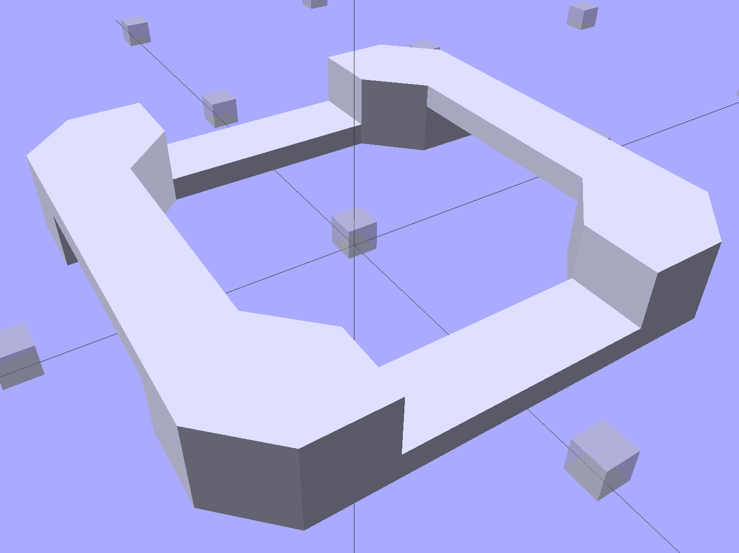
The rectangular posts in my chain mail resemble Zomboe’s original design, but with dimensions computed directly from the bar (and, thus, thread) widths and thicknesses to ensure good fill and simple bridging:
Chain Mail Link
They fit together well, but the angled post edges make the bridge threads longer than absolutely necessary along the outside edge of each link:
Chain Mail Sheet – detail
A bit of fiddling produces a squared-off version:
Chain Mail Link – Improved Posts
Which nest together like this:
Chain Mail – Improved Posts – Bottom View
Now all the bridge threads have the same length, which should produce better results.
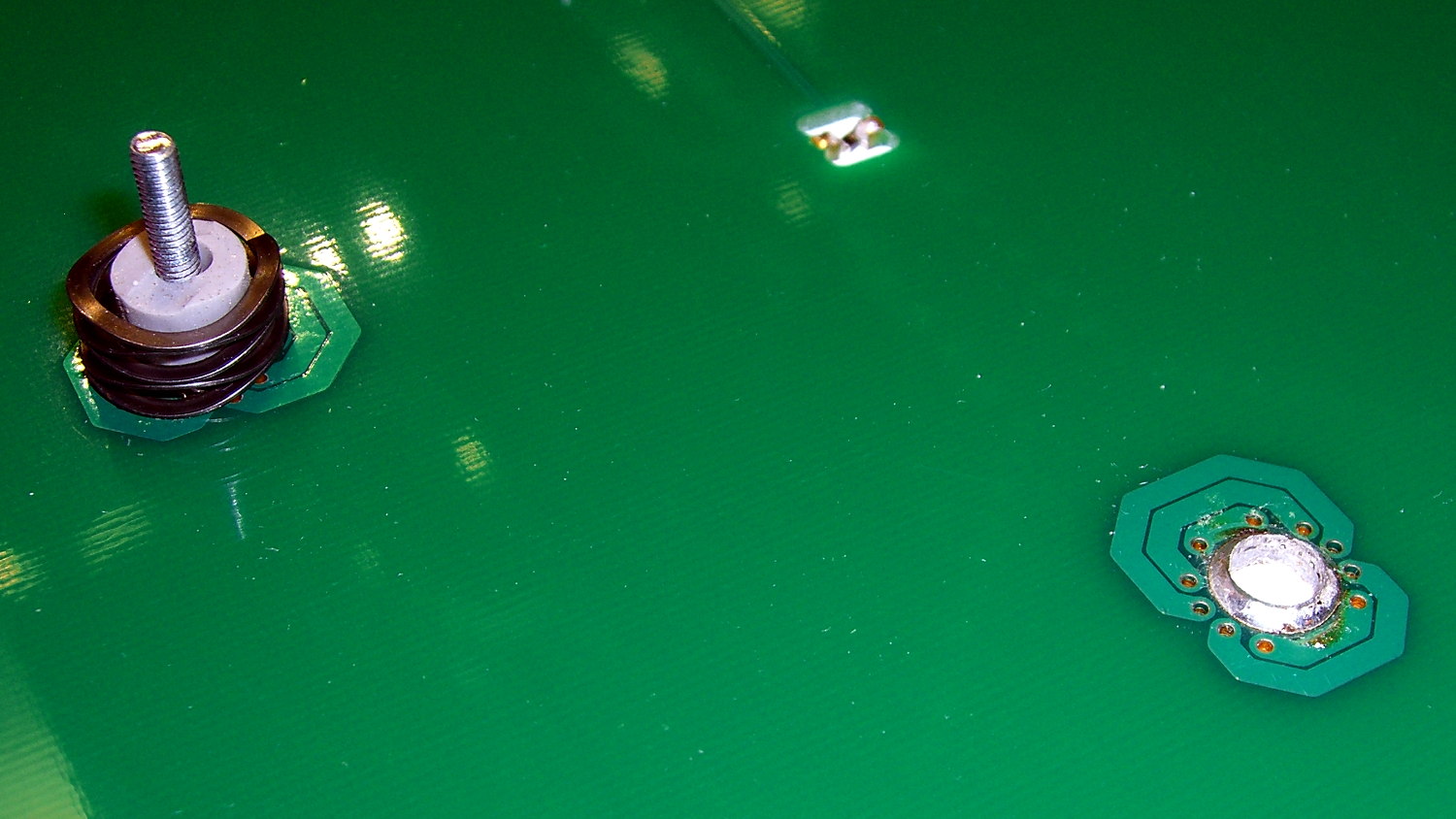
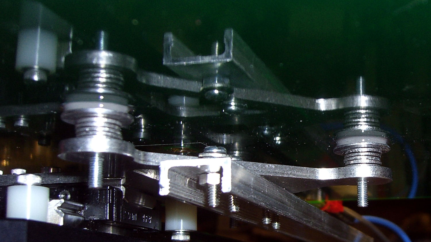
The hotrod build platform I’m using with the Makergear M2 consists of a PCB heater bonded to a glass plate, supported by three socket head cap screws soldered into the PCB. The print quality recently took a nosedive that seemed related to the first layer height, with which I fiddled more than usual, and finally the front of the platform became obviously, visibly, no-way-around-it far too high. Peering under the platform showed that the front support stud had pulled out of the solder fillet securing it to the PCB:
M2 Hotrod Platform – support stud pullout
Those PCB patterns conduct the heater current around the mounting holes: the hotrod platform has better heat distribution than the OEM M2 platform.
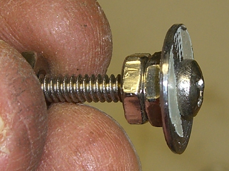
The offending screw didn’t go anywhere:
M2 Hotrod Platform – support stud in spring
The wavy spring and silicone plug press on the PCB, so the solder fillet had to support all the stress. It seemed as though the solder hadn’t bonded to the stainless SHCS, but, rather than try to fix that, I decided to put a washer on the screw. That way, the spring bears on the washer and the screw head supports the strain, with the solder fillet responsible for holding the PCB and glass plate in position.
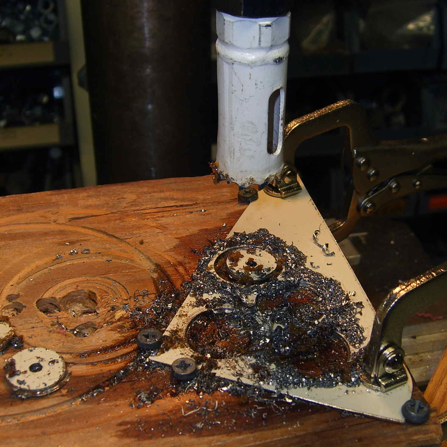
Alas, I didn’t have any washers small enough on the inside (3 mm) and big enough on the outside to support the springs, so I cut some out of a sheet steel scrap by drilling the center hole to the proper diameter, then applying a hole saw without its (far too large) pilot drill:
M2 Hotrod Platform – hole-sawing washers
That’s a lethally bad idea, as the pilot-less saw can grab the sheet and toss it across the shop. Notice the screws holding the sheet down and absorbing the cutting torque, plus the two clamps enforcing the “stay put” edict.
The other problem with not having a pilot drill in the hole saw is that it’s not guaranteed to cut a cookie that’s concentric with the center hole. Instead of taking the time to make a pilot, I just drilled and cut a few extra washers, then picked the best three of the set for finishing:
M2 Hotrod Platform – rough-cut washers
Using a screw as a mandrel, I lathe-turned the OD of the better ones to make them nice and round:
M2 Hotrod Platform – washer on mandrel
Two of the three PCB support screws were in the right place (they hadn’t come loose), so I used the M2 as an alignment fixture for the third:
M2 Hotrod Platform – aligning washers
That’s a layer of good old JB Industro Weld epoxy, rated for much higher temperatures than the platform will ever see, between the big washers and the PCB. I buttered up the head of the errant screw and the inside of the solder fillet, shoved it in, and then stacked everything together. The small washers held the big washers perpendicular to the screws while the epoxy cured.
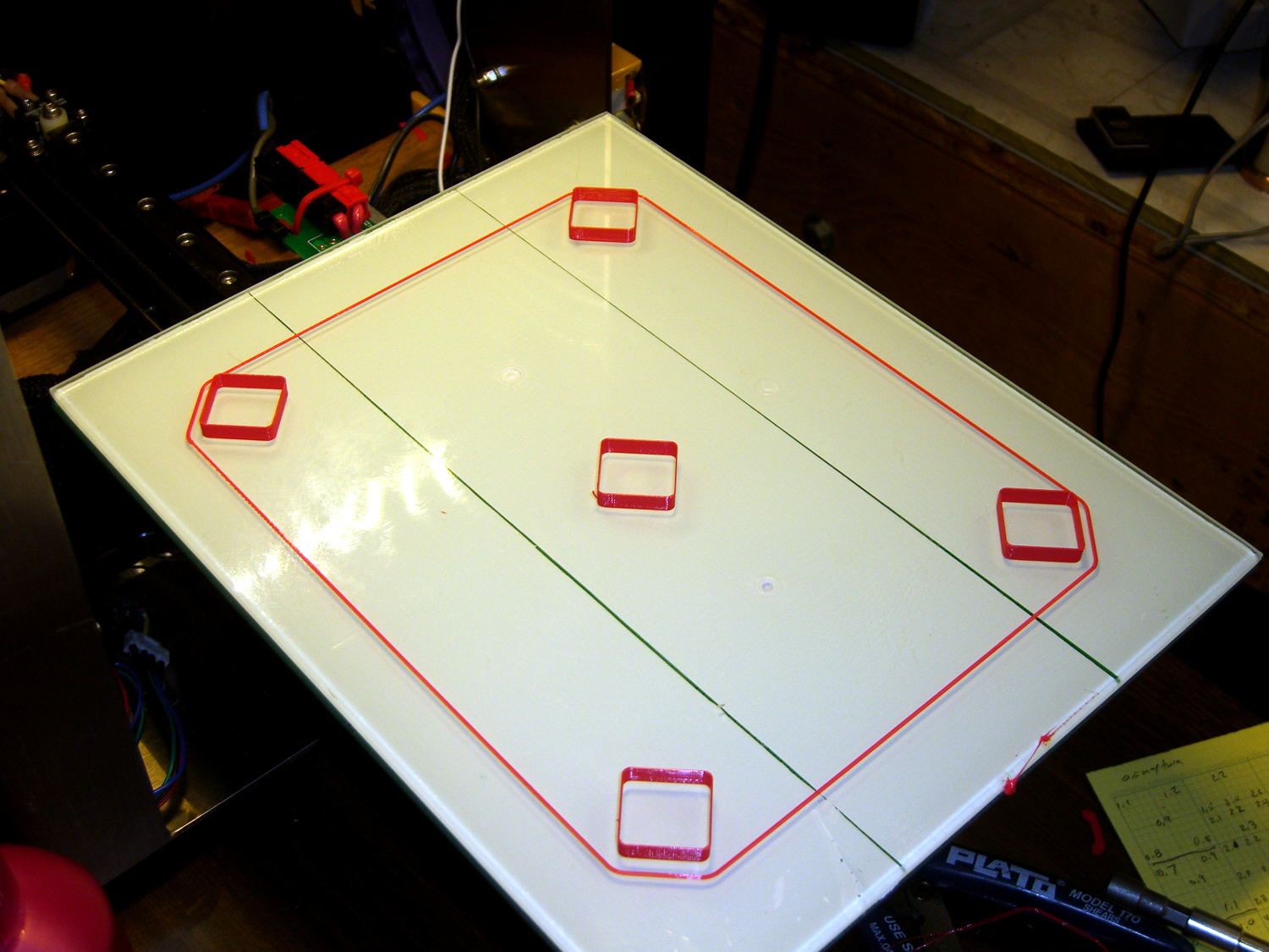
After that, I removed the small washers, reinstalled springs + silicone plugs, tightened the nyloc nuts, aligned the platform, ran off a few thinwall hollow boxes, tweaked the alignment, and it was all good:
M2 Hotrod Platform – thinwall box alignment
The rest of the story: that mumble screw pulled loose on the Friday evening before the Mini Maker Faire on Saturday morning. I did all the shop work after supper, then let the epoxy cure overnight with the platform set to 95 °F while I got a good night’s sleep. Reinstalling and realigning the platform took the better part of half an hour around breakfast, after which I tore it all down, packed it all up, and headed off to the Mini Maker Faire.
In truth, that’s the most trouble I’ve had with the M2 and it’s not Makergear’s fault: it’s not their platform. After reinstalling the platform, the alignment was no big deal and it’s been stable ever since.