The original Mood Light firmware used the current time in milliseconds as a factor in the sin() argument, assuming that the Arduino runtime would Do The Right Thing. Having been gently disabused of that notion, here’s another pass that resets the argument after every full cycle to keep the trig from going crazy. Thanks to all of you for helping out… [grin]
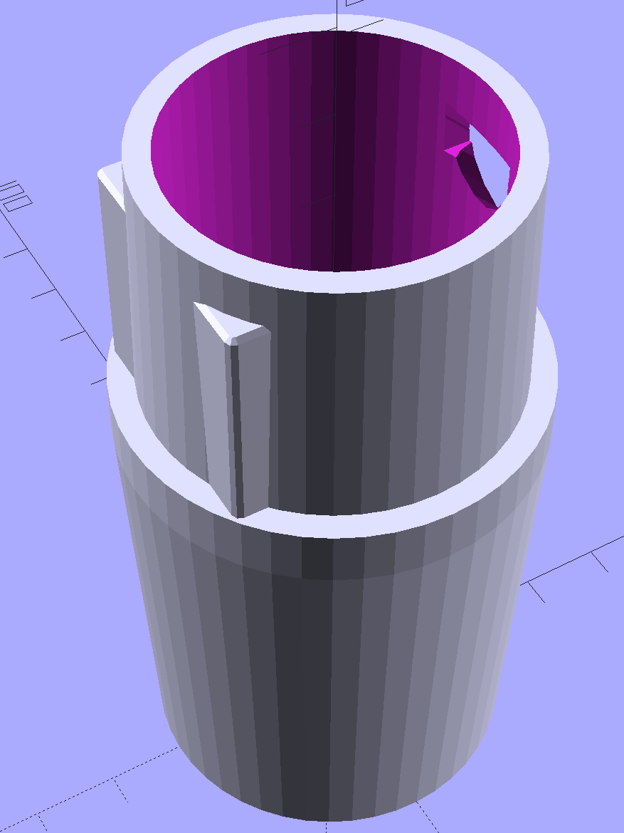
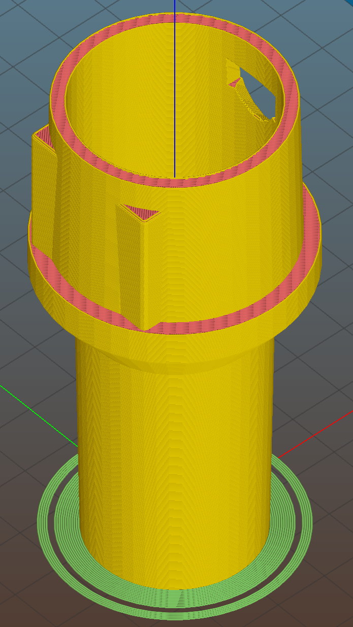
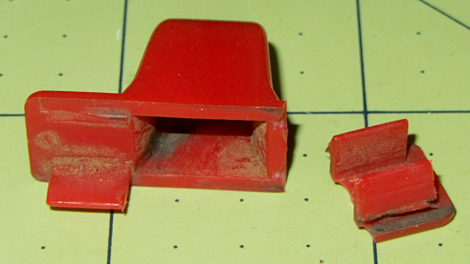
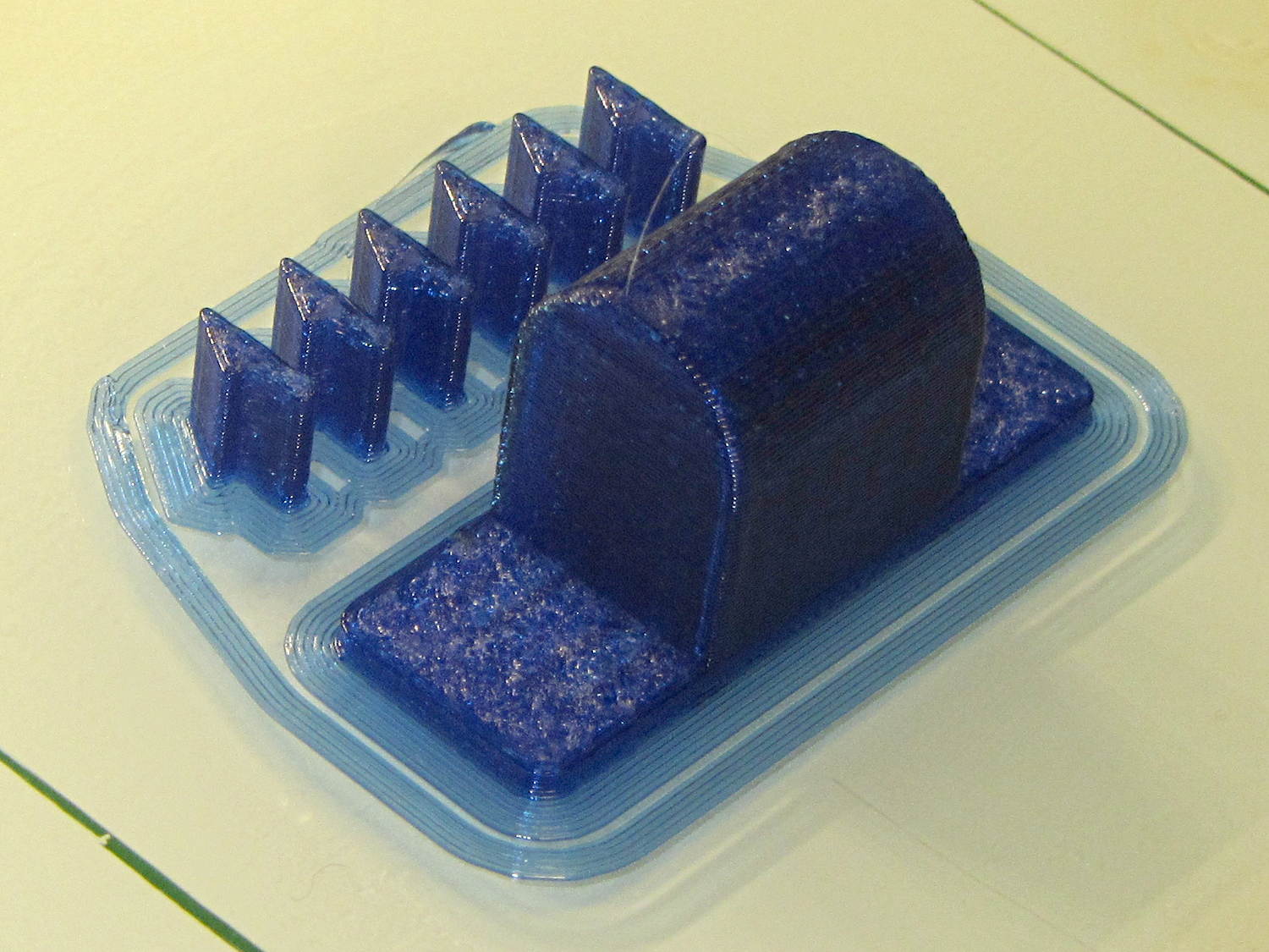
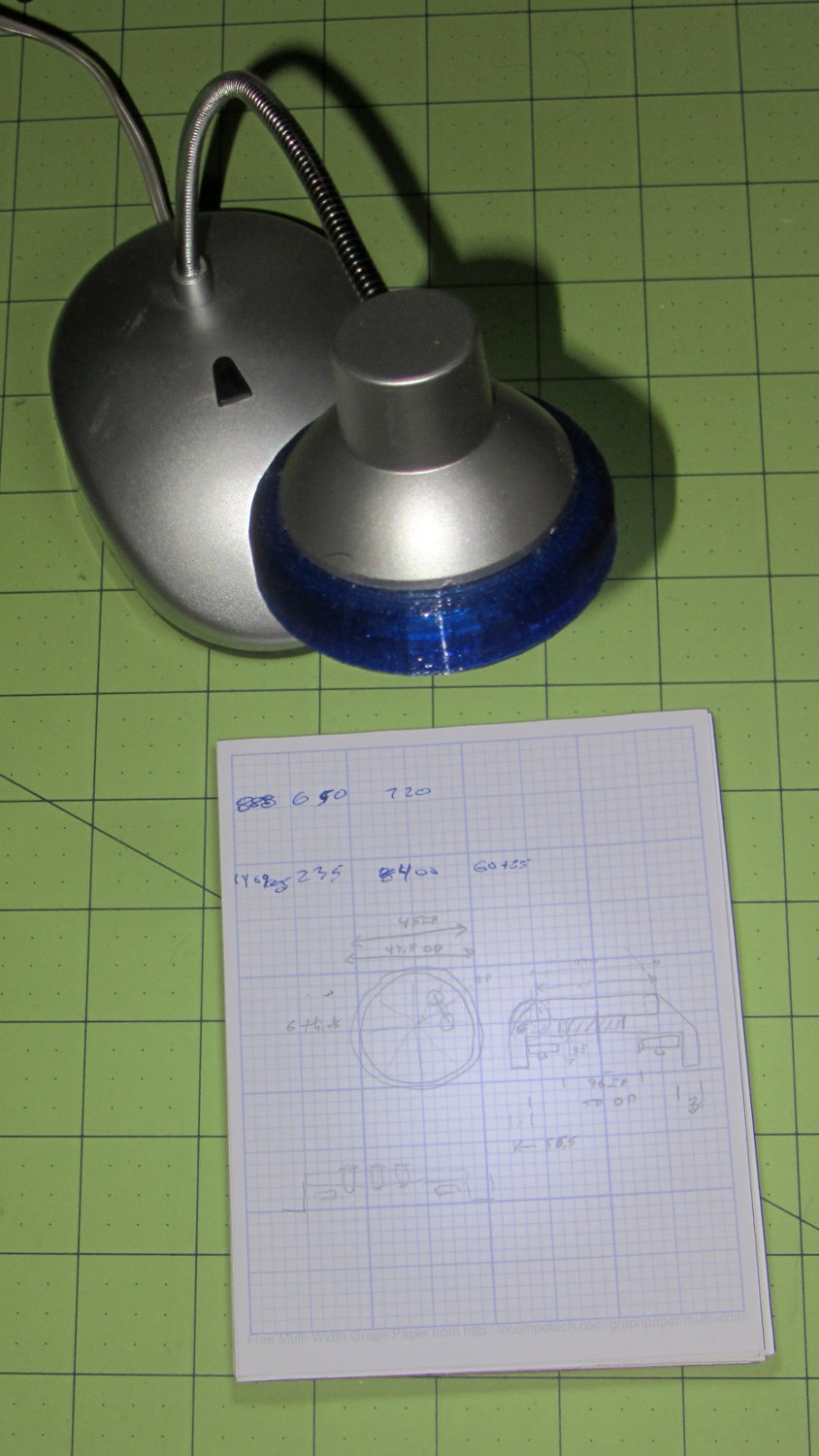
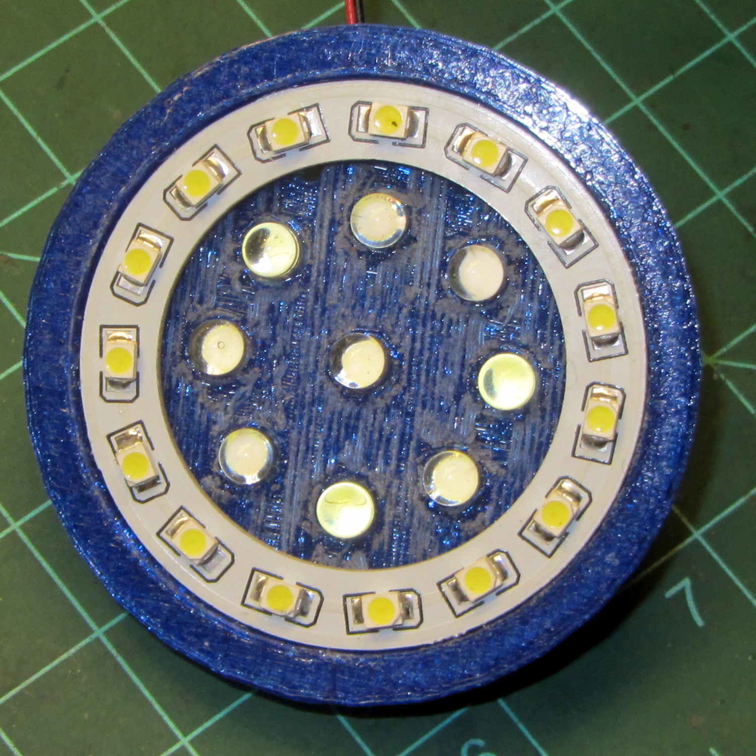
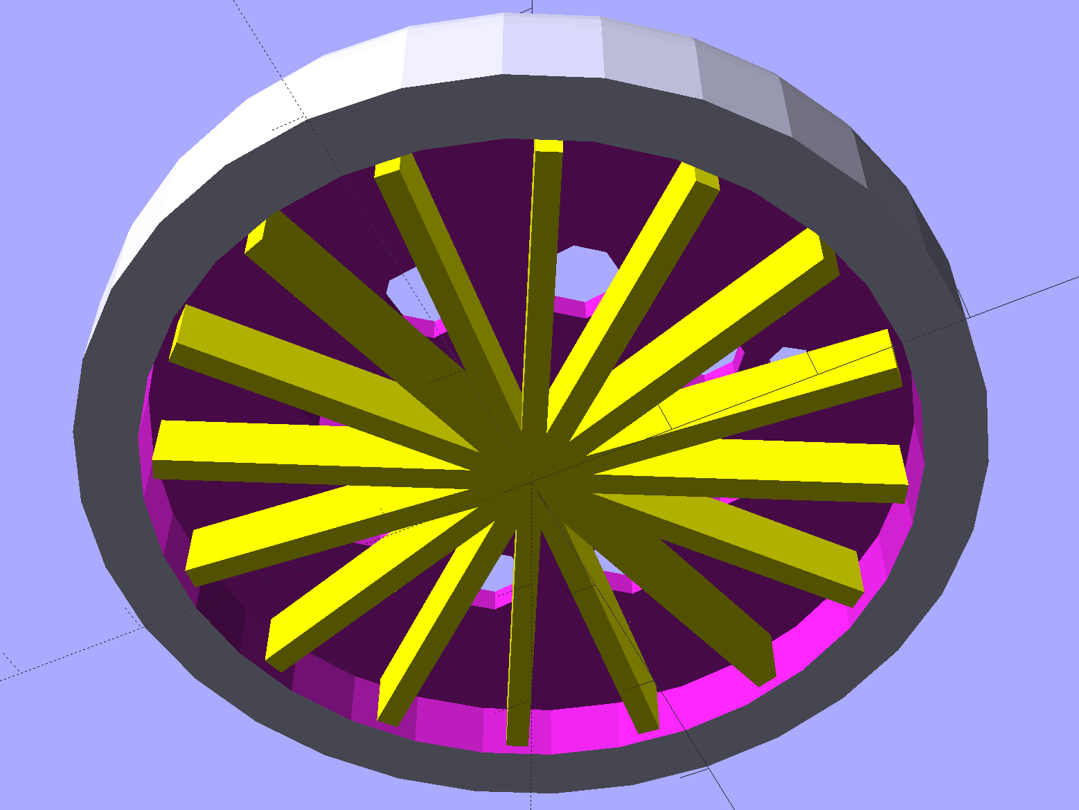
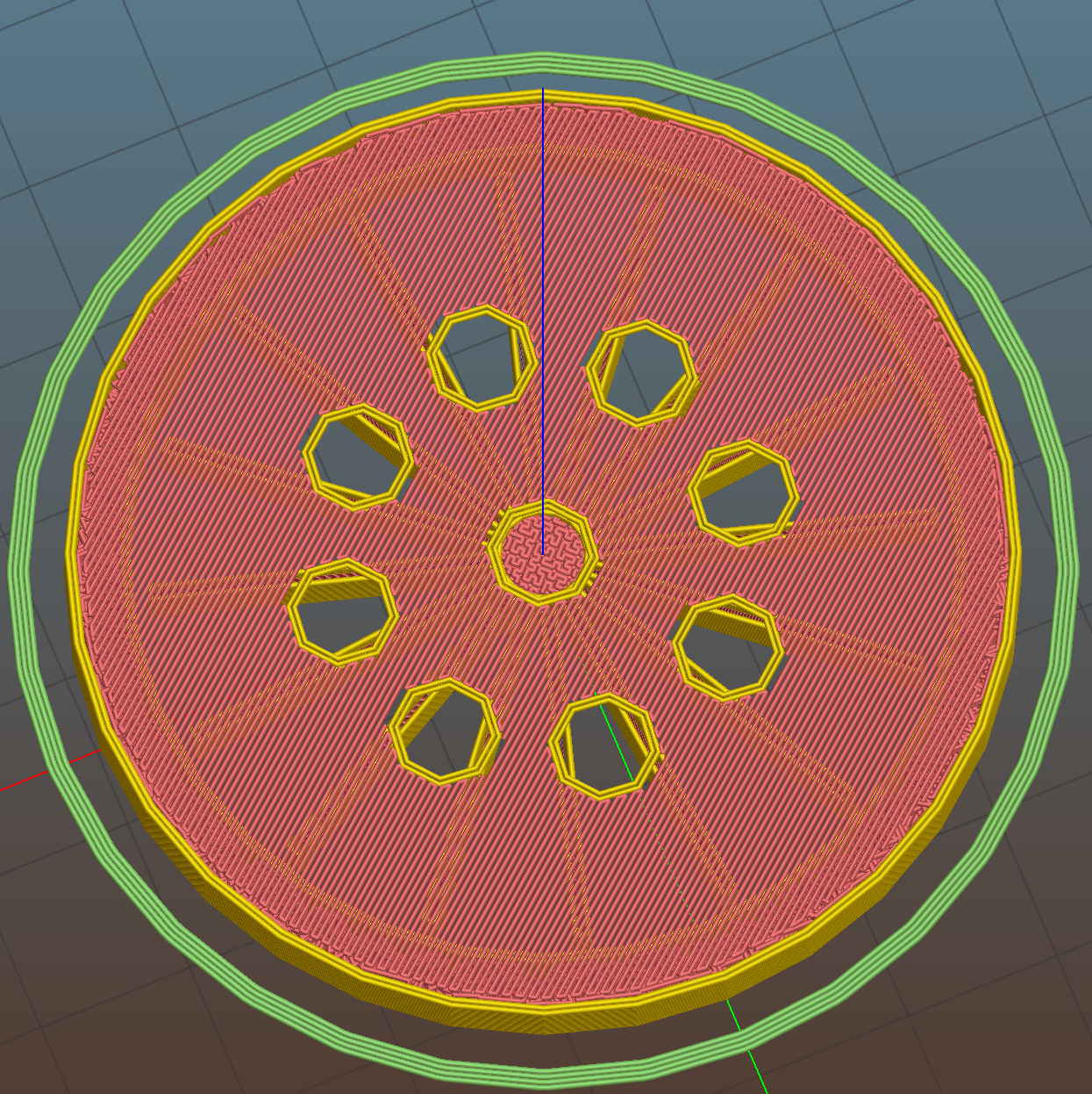
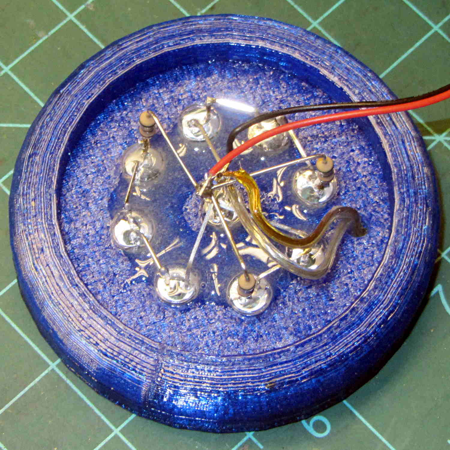
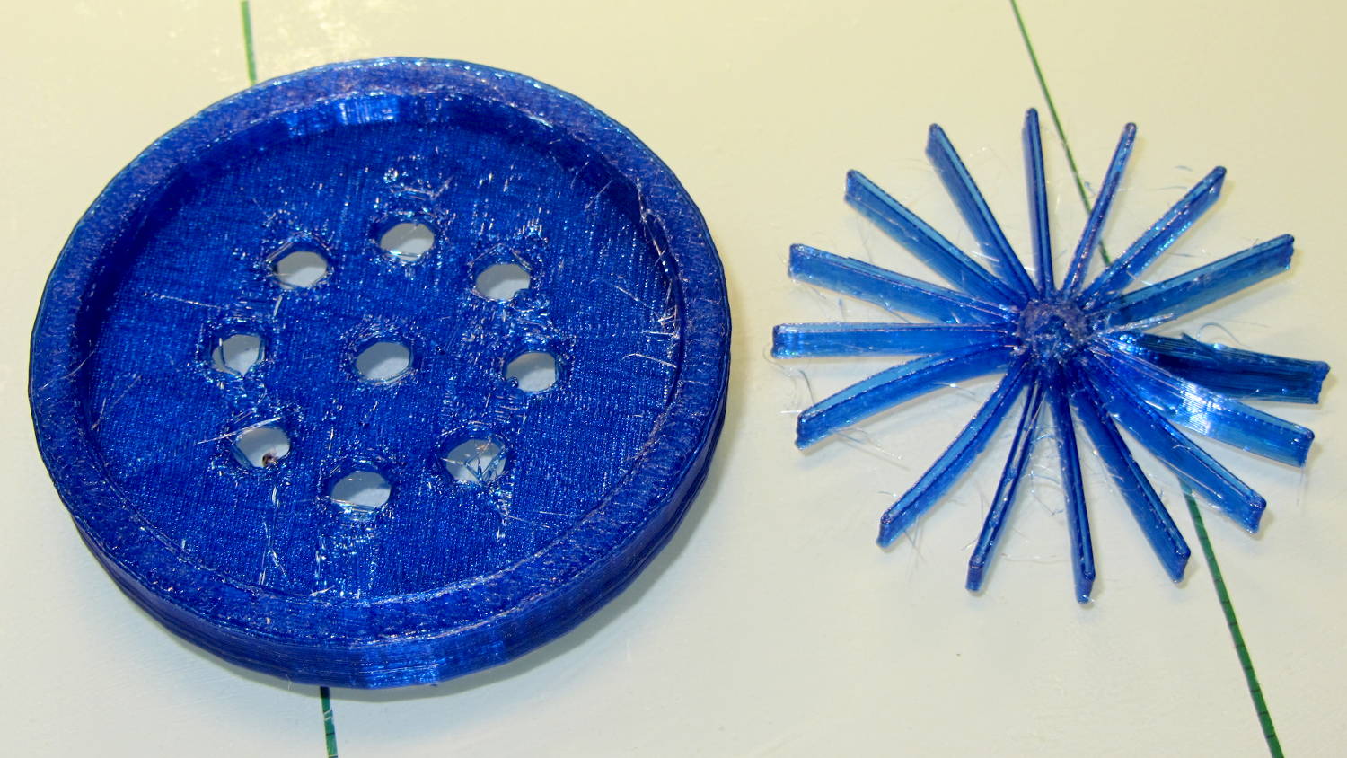
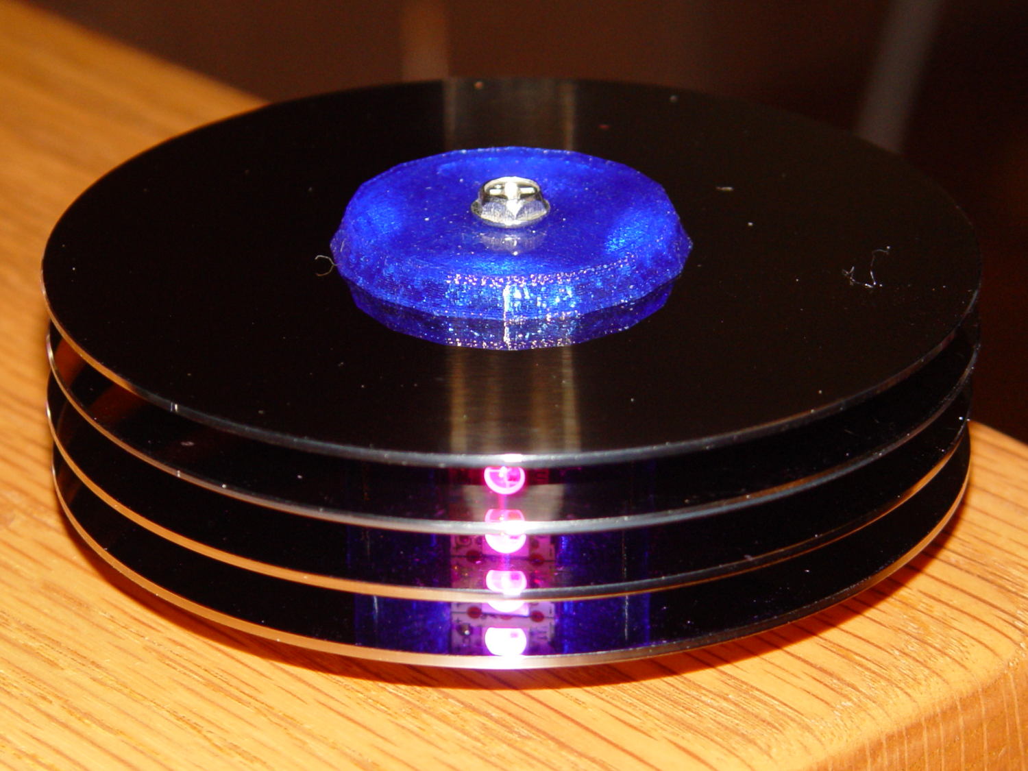
The hardware still looks like this, though:
Define a structure to hold everything needed to calculate each color, then make an array holding one structure per color:
struct pixcolor_t {
	byte Prime;
	unsigned int NumSteps;
	unsigned int Step;
	float StepSize;
	byte MaxPWM;
	byte Value;
};

enum pixcolors {RED, GREEN, BLUE, PIXELSIZE};

#define RESOLUTION 1000

struct pixcolor_t Pixels[PIXELSIZE];
The general idea is to increment the integer Step from 0 through NumSteps - 1 to create the sine wave, with the total number of steps per cycle being Prime times the RESOLUTION.
The angular argument is Step * StepSize, with the size of each step equal to 2π / NumSteps. Because Step gets reset to zero after reaching NumSteps - 1, the argument never exceeds 2π and the trig never falls off the rails.
Soooo, calculating the PWM value for each color goes like this:
byte StepColor(byte Color) {

    Pixels[Color].Value = (Pixels[Color].MaxPWM / 2.0) * (1.0 + sin(Pixels[Color].Step * Pixels[Color].StepSize));

	Pixels[Color].Step = (Pixels[Color].Step >= Pixels[Color].NumSteps) ? 0 : Pixels[Color].Step + 1;

	if (0 == Pixels[Color].Step) {
		printf("Color %d cycle end at %d\r\n",Color,Pixels[Color].NumSteps);
	}

    return Pixels[Color].Value;
}
The MaxPWM parameter limits the perceived brightness, although not the peak current. Each Neopixel dissipates 300-ish mW at full throttle, they’re mounted on a plastic structure, and there’s not a lot of air flowing between those platters; running at half power makes a lot of sense.
Initializing the structure values happens in the setup() function, because it’s easier than filling in all the array structure entries by hand:
	Pixels[RED].Prime = 5;
	Pixels[GREEN].Prime = 7;
	Pixels[BLUE].Prime = 11;

	for (byte c=0; c < PIXELSIZE; c++) {
		Pixels[c].NumSteps = RESOLUTION * Pixels[c].Prime;
		Pixels[c].Step = random(Pixels[c].NumSteps);
		Pixels[c].StepSize = TWO_PI / Pixels[c].NumSteps;
		Pixels[c].MaxPWM = 128;
		StepColor(c);
	}
The Phase value has Gone Away, because it really didn’t add anything to the proceedings. Instead, I randomize the starting Step, although there’s not a lot of randomness to be had early on in an Arduino program; that needs a bit more work. Adding a little PCB with a random noise source doesn’t seem cost-effective, although a photodetector peering out the side and adjusting the MaxPWM values might be a Good Thing.
Come to think of it, limiting the sum of the PWM values might be more useful than limiting their individual maximum values. That’s a simple matter of software…
The main() loop doesn’t have a lot to do. Every 25 ms it updates the three color PWM values, sets the new values into all 12 LED buffer locations, and sends the whole mess to the Neopixels. The RESOLUTION value acts as a gearshift between the 25 ms update rate and the speed at which complete cycles zip past. Absent the Prime factor, each cycle would require 25 ms * RESOLUTION ms to complete: call it 25 seconds.
The Prime factors slow that down proportionally and push the repetition interval out to the product of all the factors. For the (5, 7, 11) factors shown below, that’s 5x7x11x253 s = 6×10⁶ s = 70 days,
Now it doesn’t matter how often the millis() value wraps. Every now & again, MillisThen will be just under 232 and MillisNow will be just over 0, but their (unsigned) difference will be some huge number, the conditional will trip, and nobody will notice the timing glitch…
The Arduino source code:
// Neopixel mood lighting for hard drive platter sculpture
// Ed Nisley - KE4ANU - November 2015

#include <Adafruit_NeoPixel.h>

//----------
// Pin assignments

const byte PIN_NEO = 6;				// DO - data out to first Neopixel

const byte PIN_HEARTBEAT = 13;		// DO - Arduino LED

//----------
// Constants

const unsigned long UpdateMS = 25ul - 4ul;		// update LEDs only this many ms apart minus loop() overhead

//----------
// Globals

unsigned long MillisNow;
unsigned long MillisThen;

Adafruit_NeoPixel strip = Adafruit_NeoPixel(12, PIN_NEO, NEO_GRB + NEO_KHZ800);

uint32_t FullWhite = strip.Color(255,255,255);
uint32_t FullOff = strip.Color(0,0,0);

struct pixcolor_t {
	byte Prime;
	unsigned int NumSteps;
	unsigned int Step;
	float StepSize;
	byte MaxPWM;
	byte Value;
};

enum pixcolors {RED, GREEN, BLUE, PIXELSIZE};

#define RESOLUTION 1000

struct pixcolor_t Pixels[PIXELSIZE];								// everything that calculates the pixel colors

byte Map[] = {0,5,6,11, 1,4,7,10, 2,3,8,9};							// pixel numbers around platter, bottom to top.

//-- Figure PWM based on current state

byte StepColor(byte Color) {

    Pixels[Color].Value = (Pixels[Color].MaxPWM / 2.0) * (1.0 + sin(Pixels[Color].Step * Pixels[Color].StepSize));

	Pixels[Color].Step = (Pixels[Color].Step >= Pixels[Color].NumSteps) ? 0 : Pixels[Color].Step + 1;

	if (0 == Pixels[Color].Step) {
		printf("Color %d cycle end at %d\r\n",Color,Pixels[Color].NumSteps);
	}

//	printf("Step: %d Color: %d Value: %d\r\n",Pixels[Color].Step,(word)Color,(word)Pixels[Color].Value);

    return Pixels[Color].Value;
}


//-- Helper routine for printf()

int s_putc(char c, FILE *t) {
  Serial.write(c);
}

//------------------
// Set the mood

void setup() {

	pinMode(PIN_HEARTBEAT,OUTPUT);
	digitalWrite(PIN_HEARTBEAT,LOW);	// show we arrived

	Serial.begin(57600);
	fdevopen(&s_putc,0);				// set up serial output for printf()

	printf("Mood Light with Neopixels\r\nEd Nisley - KE4ZNU - November 2015\r\n");

/// set up Neopixels

	strip.begin();
	strip.show();

// lamp test: run a brilliant white dot along the length of the strip

	printf("Lamp test: walking white\r\n");

	strip.setPixelColor(0,FullWhite);
	strip.show();
	delay(500);

	for (int i=1; i<strip.numPixels(); i++) {
		digitalWrite(PIN_HEARTBEAT,HIGH);
		strip.setPixelColor(i-1,FullOff);
		strip.setPixelColor(i,FullWhite);
		strip.show();
		digitalWrite(PIN_HEARTBEAT,LOW);
		delay(500);
	}

	strip.setPixelColor(strip.numPixels() - 1,FullOff);
	strip.show();
	delay(500);

// and around the disks

	printf(" ... using Map array\r\n");

	strip.setPixelColor(Map[0],FullWhite);
	strip.show();
	delay(250);

	for (int i=1; i<strip.numPixels(); i++) {
		digitalWrite(PIN_HEARTBEAT,HIGH);
		strip.setPixelColor(Map[i-1],FullOff);
		strip.setPixelColor(Map[i],FullWhite);
		strip.show();
		digitalWrite(PIN_HEARTBEAT,LOW);
		delay(250);
	}

	strip.setPixelColor(Map[strip.numPixels() - 1],FullOff);
	strip.show();
	delay(250);

	MillisNow = MillisThen = millis();
	randomSeed(MillisNow + analogRead(7));
	printf("First random number: %ld\r\n",random(10));

	Pixels[RED].Prime = 5;
	Pixels[GREEN].Prime = 7;
	Pixels[BLUE].Prime = 11;

	for (byte c=0; c < PIXELSIZE; c++) {
		Pixels[c].NumSteps = RESOLUTION * Pixels[c].Prime;
		Pixels[c].Step = random(Pixels[c].NumSteps);
		Pixels[c].StepSize = TWO_PI / Pixels[c].NumSteps;
		Pixels[c].MaxPWM = 128;
		StepColor(c);
	}
	printf("Prime scales: (%d,%d,%d)\r\n",Pixels[RED].Prime,Pixels[GREEN].Prime,Pixels[BLUE].Prime);
	printf("Initial step: (%d,%d,%d)\r\n",Pixels[RED].Step,Pixels[GREEN].Step,Pixels[BLUE].Step);
	printf("  ...  color: (%d,%d,%d)\r\n",Pixels[RED].Value,Pixels[GREEN].Value,Pixels[BLUE].Value);

	for (int i=0; i<strip.numPixels(); i++) { strip.setPixelColor(Map[i],strip.Color(Pixels[RED].Value,Pixels[GREEN].Value,Pixels[BLUE].Value)); } strip.show(); } //------------------ // Run the mood void loop() { // printf("Loop! %ld %ld\r\n",MillisNow,MillisThen); MillisNow = millis(); if ((MillisNow - MillisThen) > UpdateMS) {
		digitalWrite(PIN_HEARTBEAT,HIGH);

		for (byte c=0; c < PIXELSIZE; c++) {
			StepColor(c);
		}

		for (int i=0; i < strip.numPixels(); i++) {
			strip.setPixelColor(i,strip.Color(Pixels[RED].Value,Pixels[GREEN].Value,Pixels[BLUE].Value));
		}
		strip.show();

		MillisThen = MillisNow;
		digitalWrite(PIN_HEARTBEAT,LOW);
	}

}