Mary wanted markers for all the perennial plantings in the yard, so we extracted the relevant details from her plant ID spreadsheet into a CSV file:
Aesculus parviflora,Bottlebrush buckeye,hang,1
Amelanchier,Serviceberry,hang,1
Amsonia Hubrichtii,Threadleaf Blue Star,post,1
Amsonia tabernaemontana,Bluestar,post,1
Ilex verticillata,Winterberry Holly,hang,8
Ilex verticillata,Winterberry Holly,hang,8
Ilex verticillata,Winterberry Holly,hang,8
This being a one-off project, I just duplicated the lines to match the number of tags shown in the last field.
This being the flowering season when identifying plants is easy (for her, anyway), I ran off a set of craft stick markers while making sure I had all the details right:

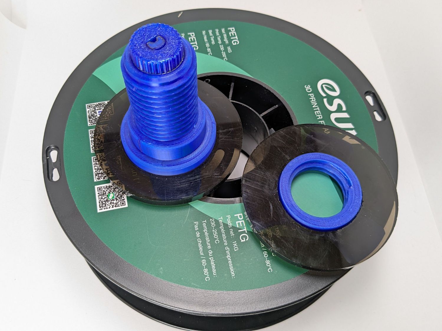
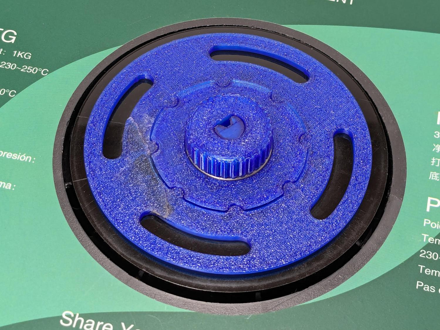
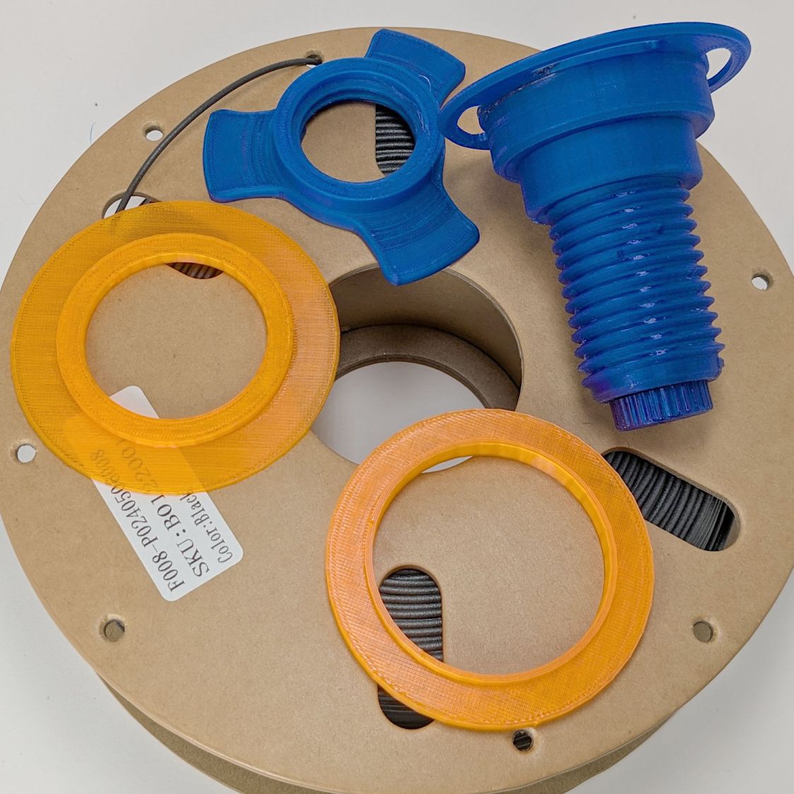
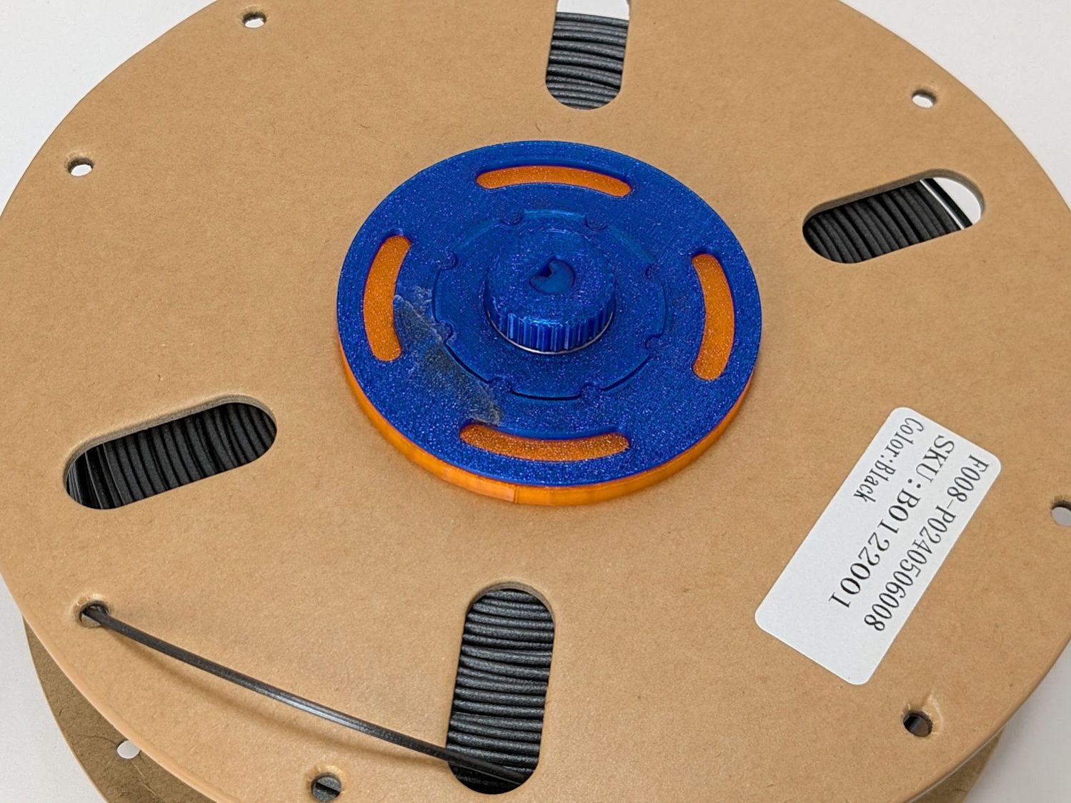
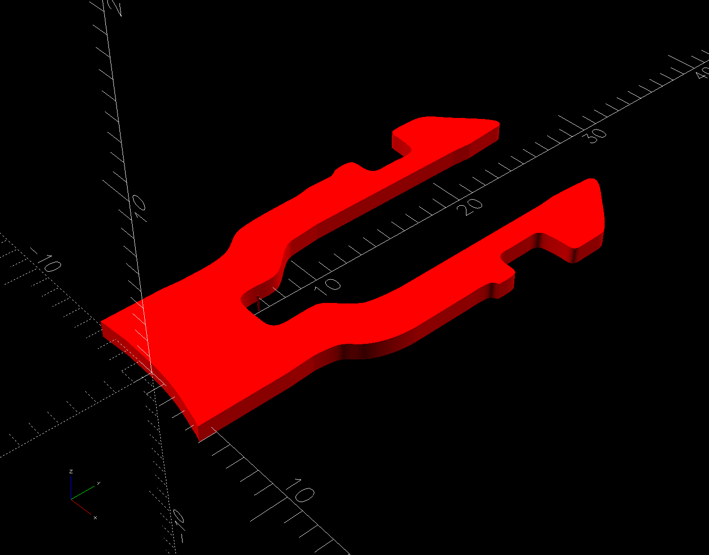
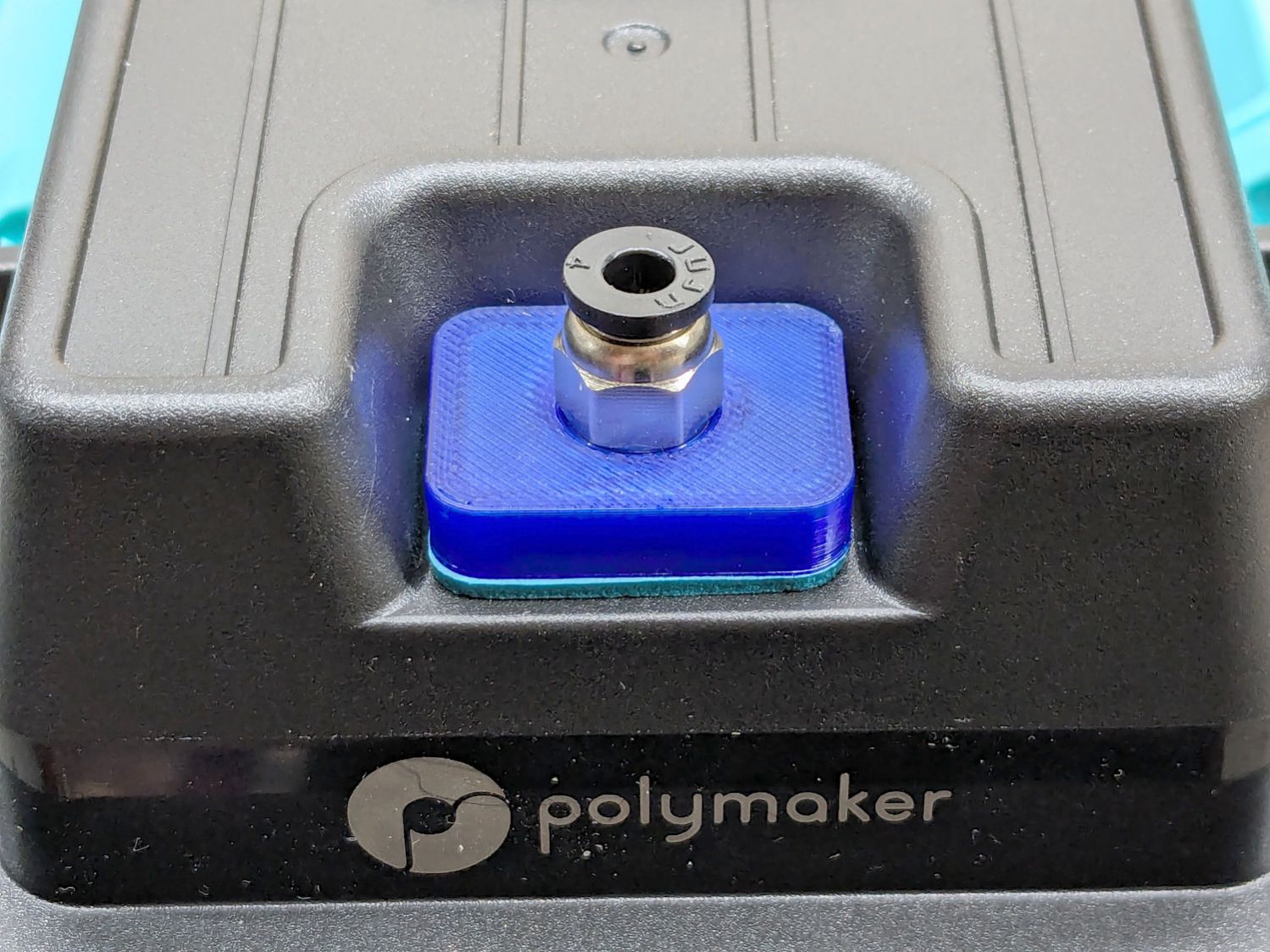
While those were being deployed, I tweaked the layout to engrave & cut the same data from 3 mm Trolase:

And then Fired. The. Laser:

While it’s kinda pretty, it is yet another reason why you should never leave your laser unattended.
They came out looking downright professional:

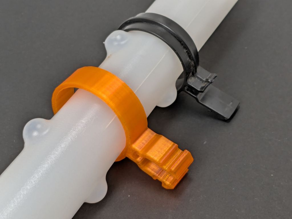
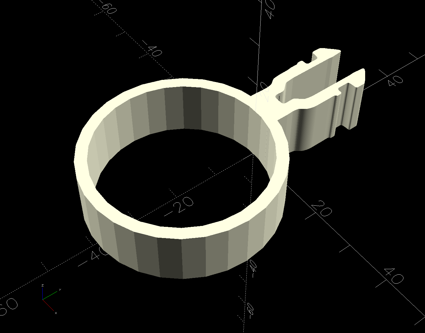
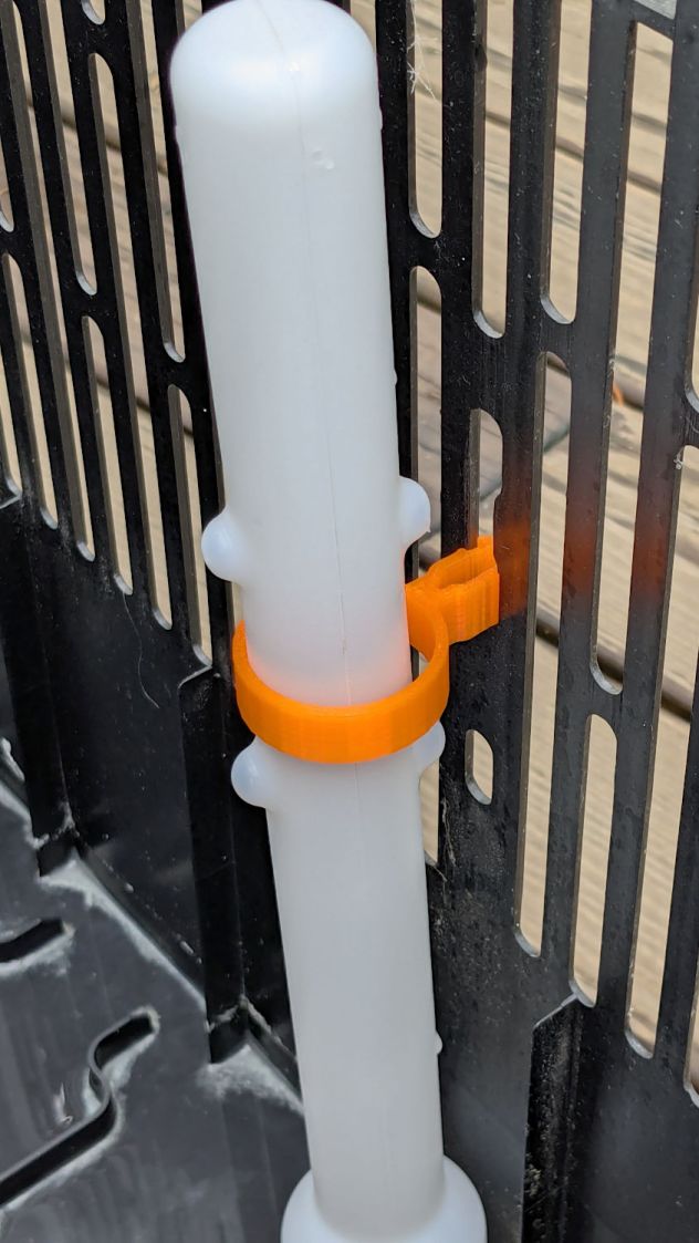
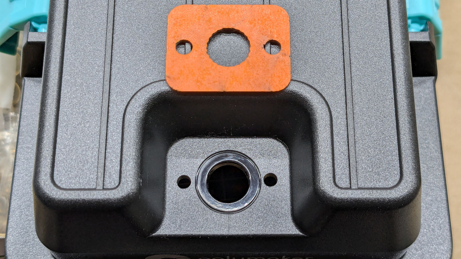
With a bit of string, they become hang tags on taller plants:
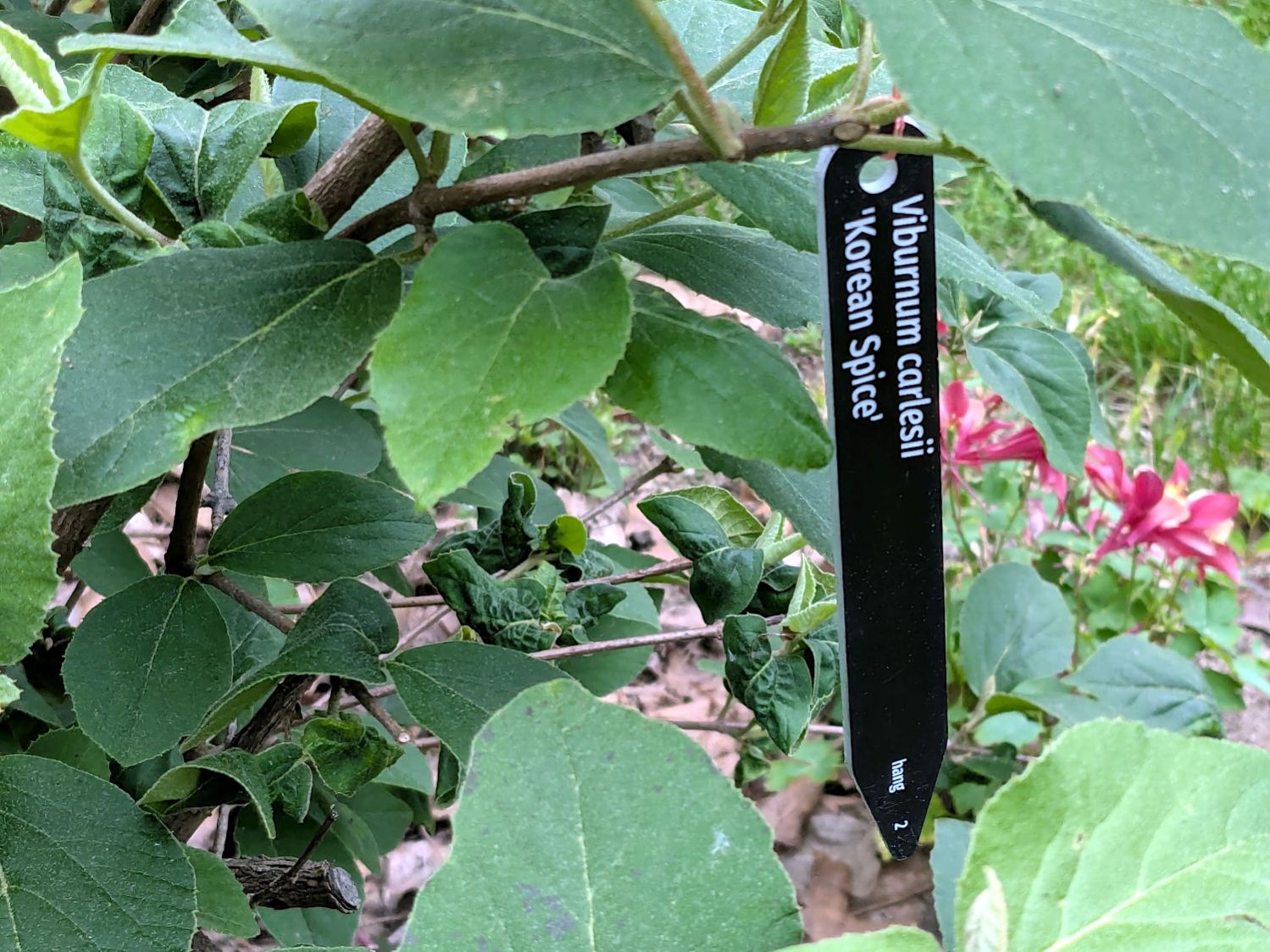
The fine print near the tip helped me get them right; you can suppress those fields if you prefer.
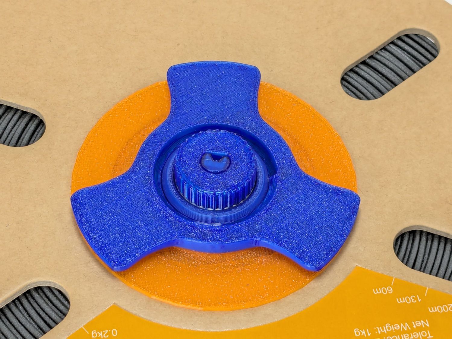
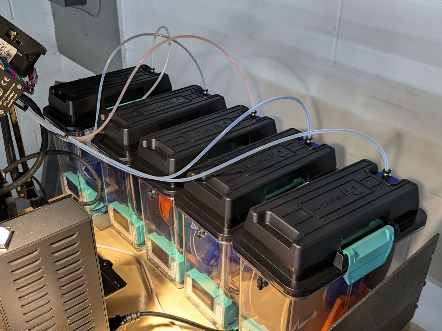
The growing season is well underway, yet still young:

Markers represent one of the few things I can help with her gardening, along with pounding stakes and manhandling wire mesh plant supports.
The LightBurn lbrn2 file as a GitHub Gist:
| <?xml version="1.0" encoding="UTF-8"?> | |
| <LightBurnProject AppVersion="2.0.00" DeviceName="FrikkenLaser" FormatVersion="1" MaterialHeight="3.3" MirrorX="True" MirrorY="True"> | |
| <Thumbnail Source="iVBORw0KGgoAAAANSUhEUgAAAQAAAAEACAYAAABccqhmAAAACXBIWXMAAA7EAAAOxAGVKw4bAAAgAElEQVR4nO2dd3wVVfqHn5l7b3pIQhIIhN6rdLAAIhZUqrqKoIDr2re46lp2Lev6U9G17bpuUVaXaq+IgCKgCAoqIk2kt1ATSCH9lvf3x5lbkjsQXJPr6pzn87kw99yZc85M5nxPe897DBERNBqNIzF/6AxoNJofDi0AGo2D0QKg0TgYLQAajYPRAqDROBgtABqNg9ECoNE4GC0AGo2D0QKg0TgYLQAajYPRAqDROBgtABqNg9ECoNE4GC0AGo2D0QKg0TgYLQAajYPRAqDROBgtABqNg9ECoNE4GC0AGo2D0QKg0TgYLQAajYPRAqDROBgtABqNg9ECoNE4GC0AGo2D0QKg0TgYLQAajYPRAqDROBgtABqNg9ECoNE4GC0AGo2D0QKg0TgYLQAajYPRAqDROBgtABqNg9ECoNE4GC0AGo2D0QKg0TgYLQAajYPRAqDROBgtABqNg9ECoNE4GC0AGo2D0QKg0TgYLQAajYPRAqDROBgtABqNg9ECoNE4GC0AGo2D0QKg0TgYLQAajYPRAqDROBgtABqNg9ECoNE4GC0AGo2D0QKg0TgYLQAajYPRAqDROBgtABqNg9ECoNE4GC0AGo2D0QKg0TgYLQAajYPRAqDROBgtABqNg9ECoNE4GC0AGo2D0QKg0TgYLQAajYPRAqDROBgtABqNg9ECoNE4GC0AGo2D0QKg0TgYLQAajYPRAqDROBgtABqNg9ECoNE4GC0AGo2D0QKg0TgYLQAajYPRAqDROBgtABqNg9ECoNE4GC0AGo2D0QKgiQ35tb5vBXbVCtsBBGqFHfiO6VTbhO2v9X0TsL1W2O7vmI4dRbW+77CJdyvf/x79NmH7bNKpfY87oi/TAqBpOKqB+4AMoANwF+AF+gFnAX2Bi61zLwD6A22Bt1GF5NdANyAT+LN17WGgK5AE/ByoACqBG4BkIA34l3XuX4FsoAdwHSDAmVZaA4CzrbQvB/oAzYAXAB+wGWhnxXcXUAWUAz8D4gA3MN8K/z2QDrQC/mjlqQ8w2Pr/Miudc4BTrXjnW/m50brHLOBxK9/7gS7W/Vxv3V8FcK1138nA89a5j1nPpydwk/Xchlj3NhA4z0r7YuuemwGzCYmIISKCRlPfVKJe1qaol/BClBjsBSYACUB34E3gS1RhuQ5YADwHpKIK1OPAQeBWoBhojBKKXwB3oAQhgCroZ6AK26+AQ1b6Y1CF4a/AFlThbwa0BFYCHwC9gXtRNeZtgGFdOwoYYYXlW3nKQonA6cAkK09NUYV7JHA3kAdciRKJvsCLwFfWOZNRhX8aSlzaAI9Y+f0tcMxK41QrjtsJt56aoMTqTJT4HbbyNMaK+wlUzT/aeh7tgI+ApdYzu8v6/RaUaOwHRKNpCMaKSEcReVBE3CKSKyKXi4gpIm+LiMv6vCgiiMhc67dkEflQRAwR+ZWI9LbC37TO7yAiP7N+v19EUqxrrrfS6Skig61rplvXpIrIndY1C6zzXCKy0Er7HyLS3ApfbJ13hogMs+J5VkTiRCTbypMpIiNEpI2IeETkT9a1LUXkEuv3N6w0PCIyzUpngfVbSsQ9/lZEuljhC61ruorIxdbvD0bc433W7/1EpK91PM36P11EbrGumRvxfOdaac8SkWZWPldZ5/9BRHcBNA1DBpADfIyq0YqAXFSzdx0Qb53Xyvo/y/qtAlVbArS2znUBf7H+bwbMQ9WuzwKNULX151Z6+1FNZBeqds9AdUU6WPEXWHH7rTgA2qP64QK8gmoBdAGWW+f81cpvFjDTSm+z9X88qpbNBgpRNSvAKut3QdXyWPkKAGXgXacGAvztRcVlQtUjftUpbwG8B3iAf1rXpaJaRomoVlQj6x4XoVpFFdZ9YD0Dl5VWIyusBaolFQBmASlAEz0GoGkozoTCxtWct3sRZQd9/CuwheWl+QQShUEvz+dgeQWfBwqY/ORyAF7ZvYtV5POp5DPwtfcQN9y/ZC3XuFawwn+YNrvfoDLNT0k3L/3j5rHeV0gz36t87T1KSZtqzj34PpV5fn5b8jlzNu+gKs3P6G2LKS6o5g3/bq596jPEBb94fzm7/aVsMYpp8/M3AHj52508aK5joeyjxXuvU+n2k9eynFHuJaz2HiF+2yx2SSlbckpoG/cGxWXVTChfRkHLSo40qWJE3iLKDvh4JrCJLwIFVCcGGLtqCfmlVXzsP8T1f18JwDX/+ZTPjQI+NfOJv20WAVM4Z+oH3MQqlhuHSfhoNkeMKoq7ehngeY8N3kKaVL3CmoqjVHbw0ynhLY6WVfHripXM2LiNqsZ+Ru9YQnF+Na+zm6v//Cnigs4Pv02et5yNRhE5l76GH6Hp2Fd52FzHe+QR9+xMtpaXwKl6DEDTUEyHGVdv5ypRBdyDyXjacDs96MVcAFwYJODiGFdgMgMAwwARKGEiA3mPbykORbmXn3G7sZqXZWcobBHn8ZV5hDsDq0Nx3k9vzjCbMDzwfijtAWQxn7NJ56Ua2QwwhQxeojhi+qCYiYwyPuQTORwKW89YnjM28zf5NhQ2myEEPDDZ+0konZ/TgTtcPejgfzOUn0zi2c9luJlZI+18xnMq89nOsVDYfi7jl8ZK3pI9obCPOJ9l5kHuC3wdCnuM/vR0ZXC+f1Eo7aE05SVjKE3kFfUsUQ0QL5NJZQ6V+EPPdyUjGbQyS7cANA2HYYSPvdbcl59wfRN5HCRYHcXZvJoS8W8kAYmO0x8RFkrbOPm6zq5aDNiElXt9UekUBsJiEsyPN2ruD9KIO+m0bW4bn4TjDMZfFREWvCTySQbjDv5ttABoGoxA9DtPiumODrS71u6Nh6iCYBjRZcMwOOk324g8tr643UbUeRIddFxOtlFtd4/Hu2+/TZxVgWiDgICNyNnqiUB5uU8LgKZh8PsFu1fPZdjV7HYFIRrbGI2aLYAgVf7owlEmvqiwChurmjJ/9Hl2QnE87Fo2HtuiFo4oXCPbR26Xpt2zPFkMA0zT0AKgaRhcLvsXucQfbapnV0O5bAqHQXRBEBulEAGPTYmxK4SRXY2QjtTRBK+rgre7c7uwSiMsNJFxhu434qI40xV1fZI7OsxOQFzHEZWEBJcWAE1ssWvi2r20PpvzKvDXWfiC2FnLnmx+7OOTaPFBcNsITQLR3Ry7VkGShM8LtQBM+8Jq18qx62L5bBTR7g71GICmQQn4BZdNX7p2s9XAsC0cdsUgiegCY3ducPS7Nm6bWE2MqC5IPOGaNbKg1C6EBkZU39wAqmzkx07kAoaEMh+MJhAIhI5DA3ZAtU1pL/V7o9JIwRMlVH6bDpUEoOBIpRYATcNgmoY1DlATuxrXrrB7MFn+4oUYhlGj1revr20Kts2JxnEE4GQwMTBrlSzDgHh3dG3fyO2JCnNhcMcdPcjOTgiFHZUqmxZNdNdHsB8DcFvFN/K3QqLjPN49ZmUlaAHQNByGzVtrN713vBc0My0On29S6PtGCkPHwZd8D2VRNXghVVHTbgGEUqIH90rxRoVtibA9qCk+Nl0Vm8FG33H6KY8+2o8XXjgjIsSmVRBxL5EtALsogzV75G92vXq756u7AJoGJyEhepCqUmymrk7QDzdNI/SydqBR1ABZK5JDNXswLIP4kPhEjq4HX/ZIXXLbFIFckkPHwXO9BBCrf21ENNuDeY+MszIQLTRBRo1qETpOj7ADiMynnRy6bcYGEmwGBuPrKNLh52dY6Wk0DUR5eXRBaGumhObZ33prOC1aJJ1kI1z1zYPFI7LWi3ebUWGNXJ7oMCM6LIHoQpSMu0YhhxNMz1HzPBV2cnfkiTgv8vrrR3Ri375La4jKuU2ac/ToBOLiwkV2gDuLioor6dmzcSjMbvA0kvBYgzo4OasMjeY7crzR+oSAC69/cuiccee0JJBqf/KyZYcYemHTGmFRA3EmVPpqtioMA8pr1cKGAWU2XQC7AbJS0xuaXgyaznpMM2ScUENUPHFRTkjSjLjjDVawf3956Lj8OHMVI/rksqX0WI10erfNICHDTXV1OL9JSW4SElxs3BjuGh2vNZXWyEVlSTg93QXQNCiGYT9wFTkuUJdBzdChTdm8uThUEHy1Cuuzz57G8OE5NcLmzh3OHXf0rNEP7927MR8tHVGjFm/VKhmRKTVidLkMDhy4jMZJ8RGhBjNmDKZr17To2QYDCquro8KOBCqPe092A6MAplUSg5MknTql4vGEi+c3m9S4RMuWSaGwsjIlaHfe2T0UVvsZBTm4ewJLl54fFR5uARxCOSpoCRv2FdK8eRIFBVV06tQo6qIG41vUssZfYD80rPlRYZpG1IR8fPx3q3Nat04JHR8mXLDi4kyuu64T+18I16imaTB6dEt8n0rIHNcw4Omn++N2mVRFjD9cdZVaOxs5ZTdwYCY5OYlsqSoJhTVqFMfkye2VR6Ja84t2rRyRE88stGwZHl+oOS1p4PNNwtUyMiycQG7zJOt+ws8vKKCJiSfXkC8qqooKU1fOAa4BvCBtoWpbgJ2UAlDZ3W87mNMg5KG8nFyH8q4yFuXtpElsktfUH8s/OYTPH10bBQJSs4CIvZEMwJKlBzl9eHboe3OS6Nu2Ma/u3BUymGmemsTIDi24d/vXoQLpNg36pmdilihjmW7dMmAzNHMlYYqLQMBPcrIagEs1PHg8BlRDfLx6zzslNiIrKR6Ka64LqJ1LWwMbjDqNiz79dCQLFuwlaaob8QWFSmpYT+7eXYrXa/0GJKd6EIGDB8OCF2whvPnmntB58TZjGkHGjWsVOjYAf0BwsxdV4BYDv4TSXC/9t80LnZixP46jRyec8Ibqk1de2cmT921i1fUXwjtQeZufPE85HdqkKucHGTHLiuZ7MHhwU7ZOLwFRNVWTJomc1a0Z7lXRLYBIU9WFC8/j2ms/xciDs4blYCSE++EAd17Ukzuf6Fnj+t5NGxPYOrlGWG5CEv7CKTXC4gwTv+/KqPQLdk9QzkQieOvh4fiuk5oCELGSTiwbHpe1Gikyj/GG67hjAACnnZbFaadlwVT41VXduH3m50yc2K7GOa1bp+ByhW0pEhJMDAMyMuI4dEi1hJKTVf09enQrvv76KACZZrwlsFLDUtDvF+bMDHsFFVFdHjf/Rg1uXAukQspnbh4y+nC3rAFg1KiWx7+Teuaf/9zMTTcp5wnDHn+f+HiTD0r2M4gsPpDzaNTWozybVABDTxBRXd2H/+L3bdtKaN++EUY5qqXyZ+C0OuJxOBkZ8XAUq+a6TDmjXBV9nomB223i8wX47W9XsWXLODxp5g/eDay9KjD4zTAMTBMS49yk4lHvI9CpUzoJe1xk+eMJmhdccklr1i8uivYYbHHrz7ty63+6RoXv2lUaGqkHMA0lBkVF0Wsp5s/fGzqOx4XfP5mrrlrOjBlht8Aul8GVV7ZjzZp85s8/QFdXmrpHjqGa2O1RbpVKDb6RsCHEq6/uYubMwfa5r2duvLFzSAB69crkgbt7MabpIm6lJ6mFbjDVskjXWYZyInk86jLv/g6/V1T4uPnmzwkEIH1tHHfd3JOssnjlgHIGynGjHq+wZcyYllxW3oqcnJQ6zy0pmciCBXmcfnp2VJfzf8ZljTUGEAgIS5eez7B/N+W5OVsAlceJE9vwx6a9WHVTQeiSQ4cq2bx5nHIc+h1o0yaFe+7pxWOPbaB10xTV5XHBtGmDufnmlfRunYEnX7WmFi48hzZt3qBflyzc69XLOG3a6cycuR0wQ++zaRo89dSpPPUUymMw4OZJ4G8oj61VIOOEt369m3i/+iP8/PIOUBKRs7rGcL7P78fgk3svIGNrHN3/ls7Gp4uYzlDK0r0YFxiYL89AvoGjyyeQkWHvTKG+GTboAz4PWG5Zi+DSpa3JWp2tfN2dg/LR9rOYZOVHh2kavPLKWSd1bmKii4svbh0VHmza/tCUen01hCgxMcIM1wq//fbuMNMy0LHGFu+5p8d/neYDD/TmgQd612jtTprUlkmT2ipvwZZzo6ysBEpLr1A+EEerMI/HZNasIVxxRbsTVlCqE/EmasANMD8wKOVKfARwY2LMAMtbU0wYTBMwoNrw87Cs40V2kljlZujRpqE/wGmnvce3314Uk/ykp9e06x74SbbyCz8J6IhyIqkFoMHo3btx3SfFgBRPzZH2fv2ygLCXIMMAnzWgVx7hTyAQ+OGah1dc0a7Oc0wCqJH2BcBwmNFnOyYziGMWJjNo2eL1sCeGhv6UwYL783h18C48hovf0I1DjGdr4jheLz8zNO2xbNmF3//pnCRjx7aq8X1O5+3KE+zzqB1mnopZVhzJ7t2lP3QWAPBGjKi53UZofCBooSsCjRqpyiI+wkT3rLOaxS6T/wVubkW5Lf43sBGuyG/HTLazxNqv6IYbOsYsM0tXHeTC+xcDUPivSpqkJ/KLy1dwx9EeTFrRnoBMUe6MT0FtzBADLiltXWNxSNtAqnLRfB4wFzUoqWkwWrdOweNx4fX6cbsNvN7AcbzrNCwe0ww194M1vSJcw5eX+0jCXWNx0htv7OKKc+uuiX8o3JwH/B1VoArBTISs0rAl1AMPrOfuu3vFJDOnnRae8/322xK6jmzMRorYQBF+saZkKlH9q50xyRLZksAZRhPaSSrb3CWcJtnK/7sLJUQae4STGxw9iQG+bdsuomXLZIxWcBw/mt85zhqcZD4jnYIGpwEjTZMvvfRj3ht9dg2nHLfdtpor1p1AAE5Gy072WdobAZ4wTjcXorYNKgO6gAyC16btCj3E889v/h1i/X4kJLi44Red8WwxeOqFgbz6l12UcQWlhg9XW4P2e95kh+8YRw9PJCMjes11Q3DpJR/x5trd6osPegxqTPetaWqLqeCGEpkniEDzvWnVKrnuk2JA5IDf3Xev5mH6qVV6VsHr1k1NrUUOAkYu3vlfRI1s/BW1F5mAsQEKZAJHqCQFD00WJoR3cWlovPBPORUMZR02jzx+zgradkuie/dMduxQ/tN/+csVvPjisJhkadOmcPN/Eu3pOqeR6jI9CHQGbkbNb2t++kQM+P3pT33wTg7gi2gWjBnTCjZCVcR4wR/+0L12LP9TKAE4B2UN+C28XbiH59dtC53Qo3M6jz7SLza5+QZYC5XH/CS86+I5OY1JtCMzNYGcLgm8ZuxEBG65JXZt7zlzBtO3r7KM/ID9HGleRXZ+gtow8k3UdkuanzyVfn+NtQAejwkuaJ2arDb0xGDAgEzYCK3ikzGqVDehRYu6bSB+SNz8DjWoNRr4N4yjFdfxGUdQCwfu+Ft3tRtpLLgQDEPNOS5+7mwCOSaLxxxkwso2NF+ZRHnqlSR0dqmdXM85QTx19ZfqapVFXN+iKIVhEXaiD7OBp87tr8ZNKoANdcSl+UmQ4HJxx7k9WFWQT6dO6aHw81vmIhtrmhznxCUSqFBhIoR39/0fxE1P4B/AMpRRS0XNMZRzzvkAr3ey7cX1TaTp4yOvbWLqQ315lPXMZS9fGCNJrnLDauuEL04Q0fe1HIu4Ppt4Hjb60kQSOGJWMbA4S+1fnwK8zMkNSml+ErTJTGH1+6O/0zV1LXn+oXEzBfgTUAUkgfSFo8vCywZPOSV2hhh795aTkuIhPmAw/9jZPDb4Gz7lAgaSjSvBYGrX9Tz47ToOHx4fWgjR0Nx331r+7/+sPdkCsGHqWLp/m652qf05yhnExJhkRaOpd1Qp+jcwQgXIWmG1ZxQ7vaV4DIOz9jWD77Ie6HssxGl9OJljVRPVIOCqAKbA71iNnBbgH/84jT/0UftGT526jgcf7PsdMvXfM3NmeDxkFC3p9ps0tSLRixoMfBUtAHYUQtB8Yt++cnJzk1RYbac8Ed8DAQn7xQ9AcM/MsjKfEvwKoLZlcBFQ2//GkXDYli0lyqdFKTU8+oRqZgnnIZRPr006peGwbduO0aFDqkrHslP69NN8Tj89W51jLQT66183cfPNXWv4RKio8LN3b5nKk7VVOEBRUTXp6XEq30dqpV1MaCA+9IyOEFqEVOM86x5Xrz5Cv34R01NWHvbuLVM+CcpU2koAPkXtRd4CvvUWs7T4ID4Etxg07ZjEoEFZ4Yjqmmv8PgtxvkDN78eBa4/Jz2iNB5P0tDja+1JDpw0cmH3cKOqb5csvoGXL1wDYxTECceAqBgagav/iE13tYBYBa+Hxxzdw++2r6dYtjY0txkE17NhRSocOb5CU5KH0faWe6xcWcsoFc4mLM6mqmgQ+CHwseCbORAR8vsmYhQYsgp4957FhwxE++OAczl2fC8Cvf72SZ57ZzMUXt+CN9WdDMbz99l4uumgJzZolsX/ypRAILoOdQVycSeVhy+Pwl+BqNUM5+QxMUQVrEWQ+9RJHj1aza9cltN6XAsWQlvYSJSXVLF06gmGf5UApnH76e3z2WQEXXJDL/PJzoBIefHAd9967hoceWsfhaeNVOuWQnDIHtVR3iipLSyFu9Cy83gDV1ZPwFJmwBNq1e5OdO4/x0UcjOHNzDphw3XWfMW3aFi6/vB0vfTYECmH27B1MnvwJzZsnkTf2UvCpexwwYB5xcS4qd6rlz4eXVZFzycsYBvj9U2A7sALcbAQeAZ4DJkOH5Eb0572Qp5RpU05n0DURAtCABP84IlD62pVU7wuQfUsCoxe2IHWhh21tLyH1Mg9NvPGwNSZZYuPSQjIt+T1ABf0T57Hm2dHwELAD2+WtGuAPwDC46y41aLNpU7FaEeeC2877EhEoK/NS+YGPBJeb8pdVNVxdHWDDv4ro4UqHI+Hdb+64aTWPS39wwYYNqoqcOnUj55q5EIBnntkMwFtv5UFXwIBfjVd/nIMHy5W9hguem7AZEaiqClDwnyqyXPHsfb0slE7l134SXGoe/+hRtfR23LilrJHRYMIxaznuqFFLKE2aCAFYuVKt/lu4cJ9auGPCJ88dAiA/v5LKFSrOL/5QEPJUtPHvRXR3pVO21YfXayVeqPKNCTu3q+bPZZct45B5GRgwbZpaefjGGzuhzRAw4OarVyGiWi9BA7XbT/3Suke/MvF3QdX7ajGTCKx6Pp9B8dnwczBZZiW6CkiHhFJXDY8mt912otG2+uXrrwtDC36a/+IVVqbmM1k+IYOXyIsvp/2eFJo8Gq8W33SOzWfEDbls5iK2czGbuYg1xaNhPLAHtfqqW4M/lh8nIwEDLvJHrPD7BPDDhbvDxmVxz6nC1v7dcAuv89uNwA/mO+H+4h9b9latxz1hrzfJ292qyVwN/SKtsTYBAZjgbQNYI/FvqbQ7vZEWOi39WQ/4Ievt8GYdu39bCn6Qz8LRnV/dXNXWRdBclGuuXjkZUBC81XAfWZardC4uCN933Ism+KHxc2GDmk5vqHtMei+8bmD55EMqnYjK7czUJmp8rhJ6ocbjjIChzgnAeG9bFWagTNP9MGRt2IWW/1EBPzR9I3yPffY2hl8DzcDkRhURrVQivo5SY1OFlJTYWNwB7N59LOQ0cus1F/HNnUXMYDB+JtOiOok1/Y5y09kr1fLkQGw+c2ZtJ4uXSeclmpgvs+fjMvWgz0a95PMb/rn86NgD4oP9ceX8qXEfDAN+O6Q7BGBTWjGTEpQ/vnatUzAPGXA5ZBUmkJjo5qqrOuD5zITzAT/0Tc1k9OiWpL7ixt9V1Q4TPG0wDJg9aDCBBIFkuDtR2Ya8MnmYEor2cGdaTwwDRp+SC+XAeTDMoxbmZ2cn4N5qwsWQWO4iFQ+madBpcxqrMgswgDPMbAwDHsrpC80BFyybcj7x8QaLJ56rzMGzYPYpg2ncOI4Db4/HENideYxrUzrSvXtjFs87H3O/wbrWhbT3KpFLSHDj+cJkWdZh8Bu0JQXThGF7mrEhQ3n4vdjdCsOAF3qdAUlAItyZ1APDgJcvU7U/beDexspMf+KgNkoMB8IoUwlSs2bJuLYZMB7ijrhIT47j5pu7Efe+K7RsWI0BvABcpRJxxxm8lDaEDcXFGAZcm9sRzm2ItySacZta4fNMwkw14EkYRg5z2cusrtt485Ph9M16F4DiG6qZM+dELoHqj3vuWRs6NgMmrYYmKzuCdkAP4DEgdosTfxRUzw8wu2o7n5HPb7xdadw4nivL2vJV4AjXF3/Gc5xO5/Q0bmrZGd8eIf21FylmIudJc/Z9VIavIsApC+ey0H0uP/e3544Pv4JqmBhYxiRXO67ydWC6bCduicmfqzZQiZ+rzA4ANHk1gQ/d+3lh/zaeqBiAAH3XZ3HIrOSMxfNZa4yhO+lkFsRTbQTIeesVDhrjucxow5uB3Ww/XMLtgS+ZSl9uNLqwQvL5ZkUx/wlsozvpnDEnm2q/8MVjR9gmx/jySAGPFPbjqK+aZRMO0iqQwu+OfMFscwgH88uYc9E2TpNMztg9n4OM5/zEXDy5Lg7tqOAXpcv5kBH8MrkLf2QNm74t4j75mil04EZ/F96UPfAhcAXgg7Nm5CACue+mQF/gNsi5IgHDgJ5fNFb2PDPAPMWgb3Imo9u3UM5+/wO8BuMCrfjotUNqkPJU9bcyQ/8K4AdfudCyOIXBNOF8ySWxxBp9jcXHC6aEPclW4qcSP4E4ITnC9t/tjp199WOPhWcb+pNJoatKPatmqGbYqTHLyo+GuPdN5hl5zGUvXY00OhxNpfX6FBa49/ElR2jvTmVscUv6fZFJXutyqowA65MLua66I+fty8VINNidVMaanKOMqWrFGVXZILAyu4DPcwo4XZrQhAQ8R002dShmRdZhcn1JtCKZARWZrG9TyJu+3eSQyBhacrm0ZWe7Y+wxyyh0VXMdnbhBOlPRxMcxl4+Pkg5yrXTkMtrSzkxluXGIeWYe50sup5BBV28aC+L28XmzAjr5GhEvLgZXNuXr1kdZ1bSAhICLvmRyZkUOC9x5LOcwTYxEJtCOq70d+Ty9gFJ8bIgr4tqqjpyzuxmuBINtHGO+K4+LKltxVkUzupHOPGMvc9nLYGlCc5JIOOaC64HrIdMfT3OS6OsRVWsAAB7PSURBVF3aWE1BXwJgcK405xJ/G2Uc1wWMFJhQ3oaBn2dBB5R9T3+4projgw5nhmp/AEREpJGI3KX+r27tF5ge+px99vsSS3JyXhHDmCFyj8iMPtvldWOXBBARU2Rasy0yafAnIuWxy8/zz2+p8Tx6Zrwj8ryI9BORXBHxxS4vPxpMkRbN3xCYLvmpFSJDRMQl8rvhqwWmy8LGeSItVdiXVxcITJffxX8h4hGRdBHviIAYxnQZas4XMUSks4jkirhc0yWdF0VMkQ3NCkU8IomJswWmiy8hIF9kF4i4RIZ1eV9gunyTXiRbk0tEDJEZV2wTmC7PN94s5S6v+ONE9k0oF5gukzyfiCBSlFwt0ldk5MhF0jthrogpkp9bKdJI5IorPpEOHV4XMUQ+bXZIBJHmzV8VmC7FqdWyr0OZiEvk+jM+E5guH6btl6LGVSKGyIqrDwtMl4fS14rEi0gjkfILfWIY0+V89yJ1j+1FpLWIac6QbOMlEVNkY/NCdX6QOJFljQ6JmCJyxAprLbIz+5gKW2qFjREJZKnz5S4r7Bn1d5GOIvJEOErknyKSLCI5InKtiLe5X6azNfTCd+jwZr2+Gyfi7bd3h9JNSpolE8Z/HPq+PqFQPSisj/k9Pq7v9smjTPZRJnmUidf0q/RTRaQ4Bg/lx8Y8kcCFgdDf7X7PWvW8XBIKu5APVZgh0iLlNYHp0orX1N/XEPnD6V+FzvWZARFEPht9OBRWnukTQaS8jy8UNjtlu4ozJZzODeZnoffF5ZopMF0GMi+UzujOi9W7xuzQu/XmpeF3sCpe/a13X1AaCtuRVaLibBtO5//c1j16RAxDhV1iLA3dY9PklwWmSzveCKVz55AvQ9cHw3ZcdywUlpdcpq4fEvFsT1XnSXpE2J0SSifE4oiwnVZYsYTuW8rCp5ocRJmz/h/wbzALDe5mTaiFsG9fObGitDRsFfLh3SNokZ/IvfSigMvpUZmOt22AtecXKm88a07wWV3H54s6PqvCn21zShjJh4xhCReZSyh9zQfTUINCzYGwnZAG4A7wtgnPIm3OKVJdzP5h45v3XXlqECsT8r3q/dpDGTQCDEi8IDwybvQywITEiWHLz7iRJnggcUr4vNaXp6gRrQvD6Xzg3qfS7khoY88vjAJ1XiLkJSkrnHJ8kKvSPnh62LombogJbjh0WkTYSBUW6QYu4VyPGhCM8BL9DnvUPTaBIp+yrN1pHFMm5C441jPs3Ve6ASas6Ri2Psq9KEmlE94cWR27gVERYdepa4lcdDhcpUEyylgN1LPNRa2jCW8uhCEiQifrhHIV0QNfruWrXUcwgLt+dgqDOkbYAXyHhTS2nOj6r6BsrY+kXDeshP2UM5e9bG1TymML++LuMhOAyy9vw0svxWaFUtAgA9T007YmF9EiP1kJ5puo57Y0Jln5cWAAWyG1z4uUlXnZtGkcnbukwUjotuNtNm0qZurU3tx1Ty9Ihwd+8zX337+Wiy5qzeuLzsSoMFi98ij9+79Ls2ZJ7Gt1KcYqLN/7M3C5DCpfuBL3FBO84IqfiYhQXT0Zt8eARyH7sVc4cqSS9947lwsubA7d4fwWi3j//f3ccktXnnxmIHjg9Rm7uPTSjzn11Cw+3XUhxmEDf7Xg8cxUBjNXToGZKm2XS6VTsPlyGneKh28hpd9sysv97NlzGS1aJsIl0HHtm2zbdoy//GUgN9/aFTLh1itX85e/bGDChDbMeedMqILPVxQwaNB7tGiRxJ7sn2GsMSLuEaqemYzrRqOm4Zygys/fgZtqPfM+wFcRYXHWJ9Kj2rnARmB/ZJwiIh+LiFs10yRV5ADlsoYjcoByqcr0q+7ByX6afo+PR8LNe0Tu52vpw1xJSZkjU6euDzWP+vV79/hN0HrmgQfWhtI1jOniMwIqn71F9aeuiVlW/vfxi+p3VtQKjxeRv6nD/futAZwWIjK61nnDRKRDrbD7RSRJHa5ff1QdfC01mryBgHVgisgSdbh5s9U/ayQit6rDsjKvOuguqjktEeHjRb2DIlJV5VcHs0T9rSPxiXpHrejXrLE643Ei8qw6zMuz2tjNReTiiEt9AdWk71wrzt+LSIo6LCioVAdfWPdTG0NEPqsVliLhvn6QziIyuFbY30VkTM0g1a66BrgamAelzXw0W/1qSCCaxyexb9+l36tS+C4MGbKAXZvK2NvmZzTbmMD0ysF0L03H9aDBxqwiFrKPzz8fVXdE9cThw+HmnwiMzVnMvF7nqGnAGcDTMcvK/z4m9i08N2DZ3zRrlqgOkone5SmD6A00MgituOzRw7ogqeYpIbt+A9XEhvCelnHhdJKSrG5Eajg/ofDGqNFyIrz4pNrcT7DXYdnVhLwWu8Jx5uZaGUwEItbSuVwGpBNtw58evsfMzPga8UcRcY8hIu4xRKpNmM0zdzML2IvaGqwfJH3h4i/GAH4rygKwZ8/Y7cX1yiu7WL78MABp3jkMPSuH6xesZACZLI4fwayjg5WBjocaD7Yh+SsDGUmLkC+IPiWZys7dDUTvtajRnBQffniQc86puR9ZebkvLFIxws3XKJ92ZwGvgVFmMF/2hU5YuvRAzDIzdmzYpPKJWwdyyrA0Gi+I59d0JbXQgzc+gD9XSMh1xcw4qboywLyH88iQOLwe4fTJ2WohxWLgj6hBldj+zTQNzEMPreP557dyZ5eeXE+neo9/9eojnHvu+1x5ZTtmzRoCwIqiwwxOXkCHDo3YujU2e14AuHkCeBbVNOgHxjmw76FyWpepdsZ9N/RUqwVjQMI2F3LzFDZuK6L7A+kU31/NNXTki9QC+t+cSdyDs2A73DauO4/f0z8meRrQcx4bRLVLPV6T8cvb0GdzY1iI2k+hNar7pPnJ8MAD66iu9rNgZx7XejqecLvv74rfL6H1Li+9tDMkABUBZf22fXvJ8S5tEFTdNYPwtMZH8HVgDIVUkUEc7r+bymNQLPADAt1JRwz4Jat4iZ2ke9w8vyC8QmLVqtoLphuOnj0z2LBBCYCXAL02ZqguyA0oK6sP0QLwE6KkxIvbDdXWLJ1h1l/hBzUOEIwxEBC6dXuHb64ai9vaZVgEWrd+jWd+cxqjY7DphEkRyqHFJ8AAWN73EB5m0oRX8DCLFjmvKdvhWHwCsHFFEb8bsBojEcbTBi+T2FV9KV9WjSLXTMIwYOnS8xr8wQSpPQbyl16bIBs1DfgtyqOy5ifDl18WUF4e9OBh1GPdrxCRGjN7mzYVceedq/FF7C+wZ0851/7uUyrEHx1BPaM2BwX4LVAJg3Zmcyc9eNTydjl6dOy2vpk3L4/Ro9XOQGU3VNMqJ5kx9y/hj6W9uGfLKeRxaXhE+UTelutxe/DrKzrVaAKem99MeaqZgppTjZ1vEk0MOPPMHFwutRU3KDvC+pWBcFx17XpciZ9EXCc+6XtiUoKyaEtEuQgSg4oIH0YvvBA7U7dRo8Jik5YWz113nkILkmlOEqbXMorwoKaBmp7gk13HJ7OOT0b4k9YkjkaGh56k0zohmfY5qco9kwDhsVLNTwSXy6jhb9I4nlfPk12PVuu86upw2QpGXY6Pmu0CRYZxHI+z9bibkJvHUXPZz6M2u7gBnvnDppDrr/HjY7uv2ez7z6TRN25GP9GCjx89yDeM5XB8JcapBknLZ1FRHqBw38SoXXsbirOHLeRjUVOTVMJnnS7k1F3Z8B5qJmIPSkA1Pxm6dUtl5UpllhvcAqz+CMdmGAYiQorhAflh3Ae7cQPvEPKzbyw18DKZSvzE4cI924jdzjcCV1jGy14jwDS2Mof3aZKWRA9XGhV+pUrXXbeCV18dFpMsVYdNthlMEwa+kqUMMS5CuZ66BbVFuOYnw8aNx8Jf6rlc+nxhZztBN/hqf8Hv68v+v0O1dX4G/A2YC28H9nLDh+F5vxa5yXz5ZYTlXV1OQb/P74fg21nF+HcI3eel8yd68wd6Ep9qkpGRQJbxEiLwpz/FaKciYOrUvgwbthCAz8hnS7MSulSlwVSUL8VjJ7xc8yMkstkf8AuuelSBxMSIhU5WC+B4Yww+ArgbeCdkN79F9ZsbA4tgpKsFBgYHLXvF3/+up/o9BmwsKaLH0+8A8OQTAxnYO5M/n72Bm7Z3YcSORvg9UzAyUbXv8NjkaZA3iysId4MWuw7QJScNfokyB54Xm3xovhteb0Bt3/UdOXy4Er8/XEu5XPXbBPD7aq/uAUFsJaChC79K4wzgnyhHivFqEFAifLXfccdqbr45Np4vDx4MO3hfvGQ/WenxzGUvCbg4y2hKHC61F18+MTPDjRcXE412tJdUtrlKGOlrAZtRg5EbOfnBIE0Uy7Ye5FenfM5jj/VnxAg1kHKovIJLBn/E1Vd34OqrOwJQGfBz2ZiP2L69jI0bxwCq6Nx379c88cRGysuvCMV53+NreGLeRg4cGB8SgJlLtvPyp7v50596qf37gI2Hi5jcbzm/+U1XpkxRPgrn7ctjTM4SPJ5wcfTXcwvA7QnPKQVnAQwMPKYLAmpgMBheJj6SG9jM1M2lqDntnUBzkN7C4bfC+4MNHpxzgsvrl+HDc7jxxq6se/8I7359Ns/O38JufkZj4onLcHFuYBFLivdTcHgCGRmx2ZPr179axd///q364oeNk8bSbV268hqcjhKj1BNEoLHlUEUFsz7bwXoKGTXqQ/bvv4w0fxwvb9nFii2HWbHicEgAVpUU8O67eYCynpvQvy1FUs2DDyp/jcuXH2bw4CYUBKr4z6vbKMfPpEnLeOedszlYXcFLS3eykH2sXXuEffsupbjKy+w1O/iKI1x99QqGDWtKa1Io9lYjCNXV4VrarIcWQORGJIYR3ds3DPBZ/goipwaTjYa3MVcS+TzwIrAT5D3YalzMCi5gDaOZ//lwNe8eg4/hgX/8cyDLd16Ab3+AjVLIEBYwsOsCHr51HR8W7icQgD/+MeywpKGZPz8vdDyeNnT5cxqsQ1lHtgV+E7Os/KhYsCDPWts+E19Es1eFzaD8WLiZ6fMJrVq9zpGjNZt1LtdM9u4ti7gWrrjiE66c9EmNabMhQxaQlvZijXp67tw8EhJmW/P5iv37y4mLm4WvquZAXMeOb/Hch5u/1/0GEN5bllczUGDnzmMUFZ24uXq8mYbKmBgCgfJqOwLIh88q8nlp447QNGKHnDRuuaVrg2cEgLXqE3ALns9MHpF+nE4TMpvG0aJRUshTUSynJhctOpcOHd4CYBUFVGT6Sc53w6Uo70O7YpaVHxU7dpRhGKqAVVX5ceNm/foiDMMgEBCqC8OF0DCgstLPyuX5NcICAeHxxzdyCcrHvqodhc9XFUQ1y0tKvFHN5aoqP3FV4T6aYaixga3flESF+Y6z0czx6v/f3/MVF1yYy9ChaoBsXUUh9/xjDWOfXcKSJSMYOrQpu3eX8cGOA/yqySpuv70bDz+sBq9N06jR3DchZAoc2QVwfx8bhJO2A/i9FeFdwHA41cxiJB9SYm1w9spDZ8JlJ5FgPRHcHnzXK5fw1aF88n9TwekfZdP6oxQOZ48nc0g85otGTa8mUZHUkUhdDzDid/cBkx6Et4O+PnEls68ZrNZPHAE+qiMuh/L009+E+7gG+H0Bpk3bHNoZJ5JQkAGG1AwzIsIisRsgszOmMSPa3HaWd3WlYzcGIMCjj67nkUfXs2nTWLp0SVdNfFHnz5q1naFDm+J2Kw/XPl+Av/zlm5AABKf/IvNTGYjuAlRLLGYB2qHcBr0DpICrxKjxGKdMWc5ll7Vp0EzYMeK+RcyaMYSLWcatfMlRcwLZxQnKDRcoX+fHox6nVFtJCq8yjBTclOKj66E0Nf3XCGUMpE2BayACSYmzqYywJjVNg1Ovns+XEbteGoY1+RU9KB4Vn8cwo36zW6HnsROF47wLwQIbmbbdqWYdi4FatlSrZpu5k0Kbgh48WMHy5Yfol5GlBq2B+HgPL7+8k/HSxjYvduKTaDSsGTCAybWoQaxkIACBvnAseCdA69a13Y80HIsW7cflMnG5TFZ3GcWC8/bzLmfjYzKNTA9Lzz/IgPbz8FWK8l94vE897lXw5EMb6cbbtOJ1uhtvs2VmCTyO8st+MXoasBahfe4iKI3aEhjcbsO+RraLU6Lj9NoYlNhea9RlmKLwH6fW8FlTgsF9AoO1d5AtW1R3otAf7ufPm5fHkCELyS8Iz2oVFVUxYcIy7lkYPX4lYrVUalEk3qiw+kZ1mp5Hza27wXXAYEni+WyuKMJlGIzztqq58KYeF9rU5tzdzfHJJHCDvCPkksg0tvDU8E08+WR/hvd+H4BHHtvAPff0rCOh+uGZZzaFjs+WZnSc0Eitm0hCeVmdRk0vrQ7HrolfHAibUwb7uF5v4OQn12yGzu2utQvznKSJrSvCHMc0w5uSVpsBLjhnEZ9+mk95+ZWYZs0W8uzZ2+nTpzEd4xtFufqKHIAM3ne1316Q/DbPLVDXaqF6QAnAYZRPswwobezl4P5y4nGRIC6Ks6rJbh/hoKyuPH2f36tRC2zSwNhn0IMMtnOMQwVVdExtFDrtwIHaTtUajldfHcbAge8BcJRqlf8KoCWqGxBb/w3/89i9syURNVnw9wKqol4FMeza4YatqPhsXqRCqqPCDrsqodZgeoXpJ6pRYYDHcIW2EA+yy1vK4sWqHd+r11wGD27CMxHbQS1apH7b7412nx8pPScqy8cbr8s0421C6xclANcDTwK3gMdvMpFloRMGks2qF2O3+Z3bPQN/Kfj+MxnvygB9nm3MmHUtie/g4vPWIym4rJILbovdEuV9+8Ji8xVHaJv6JrsWXgz3oNww6y5AndgNziWa7mizcNtCYne1fahtHz4QXbRcdpWwgJ+aA3G1BWndukLWrSvk7xEC0LOnqpiy3QnU7unY1eCRQaFZAMPAZZhRhkCxwM3fUV5FnwU6QPy3Lm6kM/9EzYvu2hU7Y/d7712D31LrxOvmMHx4U963hvvXJo5lwJ4stRnnYzHLEuNoiTAlHHAMOAO1XHghem/Ak8Dufa62meOuNAInPYBrd5pdLeq1ObPKJp3tlNJHajp/MaRuTwDTpp0BwCFvZdRvhl3XxYgUBjUSKSIhQ6BI/NSvFaIdJmWoaa+ngZ0QaCyhwg9qfjZWdOuWHrKY2nLnWLpsSeMpBlDJlZxSkc6ubqX8e8JWNbIqsfm8v3AfBjMwmIFpzODwN5Vq16BTUFtYr2zwx/Kjwm7quomRGBXWmOjmbaLYv+4um0jjbEb8M4i2Dm0m0f61UyV6KXk7km1SPj7BIrx4sXKa2you+nqXaahWRASmYYQKdbBrY1jnqrDwuYHjqWG92gHcAXyA8gg0FMzeBnNWDWHZskMYBtx8dXfVOogBE75py4RebQlUCsaDBhNox1z2cGW7Ffzz3UG07f4GbIQPA3m8/PJZMcnTjTeGS7hbTOIGmFAG/AK1HuEutC1AHVRK9CzAFimOCjPcUPvUaiNgO0BWbTMLcIjoWnibeSyqq1Hu8UGtAXaXy4gaK4C6y9CYMUtITvawxTsu6rfIQcBQWMC+S+MLRIc2dO0PwTGAD4FbUZZtW2Fi13YMSWlKy5bJasArVpa3XwFFYDYzwICv5ShfU8jnJQV4csOyt3Nn7PYrvOOOHiER8BIgocKlFHg7cAAYG7Os/CjweExqj8U1r72TB2DYVGM+X3QhiJPvZwjjsxGPUm90Sc/3V5FCdMvgZHokZWVeGtlcWxeR/X3TskuIDKuWAAkN7BIsbDv5JFBMaHeTlt+xSVTvTAH5QrhlezfOOdoMroK7mvTgLWMvq1aNjFk2du8urfH9wpwPWXLFCFiPMqCK4XjEjwG7LoBd7dreTAnVzMGXPrLGiywIhk2Y26Z2bGzER5XYzoRnj4LXZxMfMgQKhjW26T58FwK1DYtQ04nBrmR4wC/a2pGISyPD4mNgCFTTeDrtOGf9EMyAG/yd1fRkAJgLU939mPpWP2W0dKLlAPVoq/Cw9ONy2oacN3RwN4KnUP4TCuq+DadRXR3dNN8bKIsKiyzsJzLRrSssErs/aw1jvwhBEakdZv9SmDYDeXbslOjB8kDEowimE4iYWAiKQgnVtvcWCydh/9t72gQF0ATGWZ9lwA7gRPuC1KOtggFUrgowaFAWZWU+koPTV6fXEYcmhO2smynRP9SqRWub9hqGGoc5XpylNmMNZbU7+ycgssAFBxmD4w+GAS4xbO0PwL6/7nIboanBYGFP9LhrjD+4MUgz4kL3bRgGbjFsW1INwf+2ANgx1PrEkEG91PboDe2c4aeA223SvlUqN+/sRpYRz+KJB2j5WjJtM1IZkt+U8/25/LXrt7SvbsTlGW04uLmCO0p7cH/615zZsynufINDSZX8YXVPXnTt4PSfZ9Pl1TSu7dOJqR/3ZbNZzBuj9pD2rofBA5rwzy9OpdCo5unR35A5L55RZ7Wg7ZJUupHGcwO30WpLCpP6tKfpsgQm+zvwSIv19EzLoEN6I/aXlPP4uv48Hb+JsSNakv5VHPd2PYXbFnVnsXmA7FviSX8qjrZxKayovJAis4p/3LQFnlH3+rxxOmnE8dqFu8n9IJnMpHgeCPRmYFk2T3ffRM7RBOILXFyW0ppfFXblwSbr+EWH9hSt8nJD0848sb8///ZspV2/FBK/cHFebnNezhvKeqOIO1t8CXmoAefuqMpwU8SDvh3YgrLiDfIC8DI1N/L5GrXS927sW/g2GxBrNP8dh0VtaX2tqG2100Skjagtrc8VtQV9C1HbhSeJSBf1m79lQJ3TxromXkQeFZEEERlqxdlSRC4VkWYicpGoLbqHWnGkikh/K+wilXYgS0QaW2mepuLwtwyo741FJNeK90zrulOsdBuJyG1WPi608t5dRM4WkfaitvtGpGKkT20JnmaFG9b5LlHbgidZ+e9hxd864j4yIu4xTkROt/LZVESmiEhOxD0OFpG+ItInIq/jrOebJSLZVpqDI+IPPvtgmsOt624RkU41/2TaoZWm/shDuUobQ9hL0mTr/2QgB7WEegpqpuAoMATMAwZcgNoavALlbv0h65rg4PpY1OrLfCDooW40sJWwl2ZQezWmglEJXIfqKxQBXcA8ZCg/DhUoE+6RKJuODkAlqrk+GngO1UzPjEh7OarreZoKShjuCm/THbzHFNTq0CLUNLEXKER1F/dZ6ZVY6Q+17rExqvkfQC27f916Rp2tOC9AOaBZD5xthfVAmaFXWfcoqAH8diiz/olWGsUoW5VPrfgM1GK5CAyRWBoean7yjEAV7jtQvhNvQ4lBFsrYLB/VfC1AFZYOwK9RptWFKEvLLJSb+pFWPIdQhcwABqCavZtQQjEBZY49G1UoWqNc3O0FfoeafWgEDEaNId2FKmDxqMI3HmXZebUVno5a3BUUob0oUWgMdLHS+hw1BnUrsAG4E9W8zgGeQBXC2634mqAE6xrrHotQhTALtSP3WJRr+aPW87sUGAL8C9XEPxPleQqUMCVbz+w+lBu/263nkoxylDvaemYFKEFKt+5xEHAt8G+UQAcRjaa+GS/hZvYbIuIXkXtFNUszROQhEakWkRJRTdsEEblSRCqs8DtFNcWTReQJESkVkV6imv+ZoprJIiJnWd/bicgSK+w6K42mIvKsiPhEZK+Euwq3iUiViFSKyNUikiiqyfyqiHhF5BEr72lWPvyimtctrLTGWemMs763EJF3RSRgnZ9mXT/VupejVt4TrfQqrfRvs/KTJCJ/tfI5zcp3hnUfIiLni2rKZ4nIS1bYVVbaOSIyw7p2l6jmfSMRuSPiHq+0nq9HRN6TKHQLQNMw7AFa1QorRK2hOFkqgUhL3l2oLkFuRNg2oD01h/APAM2+Qzp2HEXV+kF2oAbiWkeE7SRcOx/vurqohigThNr53466x0j2olakfk+0AGg0DkYPAmo0DkYLgEbjYLQAaDQORguARuNgtABoNA5GC4BG42C0AGg0DkYLgEbjYLQAaDQORguARuNgtABoNA5GC4BG42C0AGg0DkYLgEbjYLQAaDQORguARuNgtABoNA5GC4BG42C0AGg0DkYLgEbjYLQAaDQORguARuNgtABoNA5GC4BG42C0AGg0DkYLgEbjYLQAaDQORguARuNgtABoNA5GC4BG42C0AGg0DkYLgEbjYLQAaDQORguARuNgtABoNA5GC4BG42C0AGg0DkYLgEbjYLQAaDQORguARuNgtABoNA5GC4BG42C0AGg0DkYLgEbjYLQAaDQORguARuNgtABoNA5GC4BG42C0AGg0DkYLgEbjYLQAaDQORguARuNgtABoNA5GC4BG42C0AGg0DkYLgEbjYLQAaDQORguARuNgtABoNA5GC4BG42C0AGg0DkYLgEbjYLQAaDQORguARuNgtABoNA5GC4BG42C0AGg0DkYLgEbjYLQAaDQORguARuNgtABoNA5GC4BG42C0AGg0DkYLgEbjYLQAaDQORguARuNgtABoNA5GC4BG42C0AGg0DkYLgEbjYLQAaDQORguARuNgtABoNA5GC4BG42C0AGg0DkYLgEbjYP4fuW9PM0gObQkAAAAASUVORK5CYII="/> | |
| <VariableText> | |
| <Start Value="0"/> | |
| <End Value="35"/> | |
| <Current Value="0"/> | |
| <Increment Value="1"/> | |
| <AutoAdvance Value="0"/> | |
| <Filename Value="Z:/Project Files/Laser Cutter/Gardening/Plant Markers/Perennials.csv"/> | |
| </VariableText> | |
| <UIPrefs> | |
| <Optimize_CutSelected Value="1"/> | |
| <Optimize_UseSelectedOrigin Value="0"/> | |
| <CutOrigin Value="2"/> | |
| <AlignH Value="0"/> | |
| <AlignV Value="2"/> | |
| <Optimize_ByLayer Value="0"/> | |
| <Optimize_ByGroup Value="-1"/> | |
| <Optimize_ByPriority Value="1"/> | |
| <Optimize_WhichDirection Value="1"/> | |
| <Optimize_InnerToOuter Value="1"/> | |
| <Optimize_ByDirection Value="1"/> | |
| <Optimize_ReduceTravel Value="1"/> | |
| <Optimize_HideBacklash Value="0"/> | |
| <Optimize_ReduceDirChanges Value="0"/> | |
| <Optimize_ChooseCorners Value="1"/> | |
| <Optimize_AllowReverse Value="0"/> | |
| <Optimize_RemoveOverlaps Value="1"/> | |
| <Optimize_OptimalEntryPoint Value="1"/> | |
| <Optimize_OverlapDist Value="0.025"/> | |
| </UIPrefs> | |
| <CutSetting type="Cut"> | |
| <index Value="7"/> | |
| <name Value="C07"/> | |
| <LinkPath Value="Trolase/1.6000/Cut_copy"/> | |
| <minPower Value="50"/> | |
| <maxPower Value="60"/> | |
| <maxPower2 Value="20"/> | |
| <speed Value="20"/> | |
| <dotTime Value="1"/> | |
| <dotSpacing Value="0.25"/> | |
| <priority Value="1"/> | |
| <tabCount Value="1"/> | |
| <tabCountMax Value="1"/> | |
| </CutSetting> | |
| <CutSetting type="Scan"> | |
| <index Value="9"/> | |
| <name Value="C09"/> | |
| <LinkPath Value="Trolase/Filled/0.2 mm – w/o cover"/> | |
| <minPower Value="30"/> | |
| <maxPower Value="30"/> | |
| <maxPower2 Value="20"/> | |
| <speed Value="400"/> | |
| <runBlower Value="0"/> | |
| <dotTime Value="1"/> | |
| <priority Value="0"/> | |
| <tabCount Value="1"/> | |
| <tabCountMax Value="1"/> | |
| </CutSetting> | |
| <Shape Type="Group" CutIndex="0"> | |
| <XForm>1 0 0 1 532.29694 -96.67926</XForm> | |
| <Children> | |
| <Shape Type="Group" CutIndex="0"> | |
| <XForm>1 0 0 1 0 0</XForm> | |
| <Children> | |
| <Shape Type="Text" CutIndex="9" Font="Fira Sans Condensed Medium,-1,4096,5,400,1,0,0,0,0,0,1,0,0,0,1" Str="%0" H="7" LS="0" LnS="0" Ah="0" Av="1" Italic="1" Weld="1" Eval="2" HasBackupPath="1"> | |
| <BackupPath Type="Path" CutIndex="9"> | |
| <XForm>1 0 0 1 942.73126 261.87103</XForm> | |
| <VertList>V-0.23193359 4.1088867c0x1c1x1V-0.70751953 4.4443359c0x1c1x1V-4.3125 -0.46875c0x1c1x1V-3.8300781 -0.8046875c0x1c1x1V-3.3759766 1.8793945c0x1c1x-3.7535849c1y1.790705V-3.1918945 1.9233398c0x-2.6993594c0y2.1300538c1x1V-2.3476563 3.1357422c0x-2.293736c0y3.4581332c1x-2.3706686c1y2.6020842V-2.6005859 4.0351563c0x-2.9894748c0y4.3835983c1x-2.3865347c1y3.7881236V-3.9790039 4.0703125c0x-4.4930968c0y3.6216645c1x-3.5728583c1y4.3984771V-4.3608398 2.2700195c0x-4.1466784c0y1.9466174c1x-4.6485505c1y2.8887255V-6.7324219 -0.56445313c0x1c1x-7.0442781c1y-0.628362V-6.4916992 -0.50341797c0x-6.0288c0y-0.30890119c1x1V-5.4770508 0.52929688c0x-5.0886865c0y1.4212168c1x-5.6633682c1y0.063037992V-5.137207 3.3652344c0x-5.1979117c0y3.682364c1x-4.9705787c1y2.4068079V-5.6557617 4.1376953c0x-6.2415109c0y4.4494987c1x-5.3852396c1y3.9614162V-7.4018555 3.8183594c0x-7.7987838c0y3.3320541c1x-6.9643793c1y4.3172956V-8.1435547 2.1254883c0x-8.263134c0y1.5385985c1x-8.0551319c1y2.7469599V-8.1611328 0.34521484c0x-8.1020756c0y0.029741585c1x-8.2691002c1y0.93435276V-7.6464844 -0.42236328c0x-7.3687449c0y-0.57792407c1x-7.9158998c1y-0.24793202V-3.6293945 2.4033203c0x-3.7565963c0y2.4308894c1x-3.4959092c1y2.3775592V-3.8623047 2.6679688c0x-3.9313636c0y3.0249016c1x-3.8511212c1y2.538295V-3.5961914 3.6689453c0x-3.4504697c0y3.7915676c1x-3.8333888c1y3.3934312V-3.0854492 3.6889648c0x-2.9691083c0y3.5249679c1x-3.2403212c1y3.7998056V-2.9775391 3.1230469c0x-2.9819489c0y2.8847408c1x-2.9297094c1y3.3183489V-3.2485352 2.4897461c0x-3.3578269c0y2.4088938c1x-3.0791974c1y2.6574781V-7.0551758 0.072753906c0x-7.2375274c0y0.13229126c1x-6.931881c1y0.048256218V-7.3769531 0.48828125c0x-7.4597912c0y1.3632873c1x-7.3649454c1y0.29683226V-7.003418 3.0600586c0x-6.921329c0y3.2661953c1x-7.3317604c1y2.2447736V-6.6005859 3.5727539c0x-6.4410243c0y3.6869688c1x-6.7814488c1y3.4442253V-6.0766602 3.5444336c0x-5.9342451c0y3.3418555c1x-6.2229805c1y3.6751823V-5.8964844 2.8486328c0x-5.8800154c0y2.0966039c1x-5.8702893c1y3.0948718V-6.2958984 0.65087891c0x-6.3773184c0y0.44464713c1x-6.0158787c1y1.3490227V-6.6967773 0.13720703c0x-6.803812c0y0.071287751c1x-6.5165076c1y0.26629537V-1.0375977 -0.5703125c0x-0.91575849c0y-0.55250686c1x-1.4154756c1y-0.65857613V-0.68896484 -0.45654297c0x-0.0539186c0y-0.053463995c1x-0.79785395c1y-0.51403111V-0.15283203 1.4365234c0x-0.36886871c0y1.7619456c1x0.1765492c1y0.76031125V-1.1450195 1.8295898c0x-1.6239505c0y1.735184c1x-0.76473242c1y1.9187716V-2.105957 0.88916016c0x-2.2257621c0y0.53511608c1x-2.0012426c1y1.3659439V-2.027832 -0.18505859c0x-1.8089585c0y-0.5054903c1x-2.1976027c1y0.14792463V-1.293457 -0.046875c0x-1.4760317c0y0.01951021c1x-1.1272892c1y-0.081037551V-1.5483398 0.3984375c0x-1.5575511c0y0.66468936c1x-1.5835676c1y0.20738885V-1.331543 1.1469727c0x-1.207687c0y1.3028165c1x-1.4816208c1y0.92685473V-0.81201172 1.2802734c0x-0.72317708c0y1.227167c1x-0.99560022c1y1.3572335V-0.65332031 1.0327148c0x-0.58892941c0y0.7110455c1x-0.66448605c1y1.135609V-0.84619141 0.10742188c0x-0.95595026c0y-0.021929294c1x-0.6586473c1y0.37657687</VertList> | |
| <PrimList>L0 1L1 2L2 3L3 0L4 5B5 6B6 7B7 8B8 9B9 4L10 11B11 12B12 13B13 14B14 15B15 16B16 17B17 18B18 10B19 20B20 21B21 22B22 23B23 24B24 19B25 26B26 27B27 28B28 29B29 30B30 31B31 32B32 25B33 34B34 35B35 36B36 37B37 38B38 33B39 40B40 41B41 42B42 43B43 44B44 39</PrimList> | |
| </BackupPath> | |
| <XForm>1 0 0 1 410.43433 358.55029</XForm> | |
| </Shape> | |
| <Shape Type="Text" CutIndex="9" Font="Fira Sans Condensed Medium,-1,4096,5,400,0,0,0,0,0,0,1,0,0,0,1" Str="'%1'" H="7" LS="0" LnS="0" Ah="0" Av="1" Weld="1" Eval="2" HasBackupPath="1"> | |
| <BackupPath Type="Path" CutIndex="9"> | |
| <XForm>1 0 0 1 942.73126 269.87103</XForm> | |
| <VertList>V-2.09375 4.1157227c0x1c1x1V-2.6401367 4.4443359c0x1c1x1V-5.5664063 -0.47607422c0x1c1x1V-5.0200195 -0.8046875c0x1c1x1V-4.96875 1.8833008c0x1c1x-5.408185c1y1.7829214V-4.7636719 1.9433594c0x-4.4091039c0y2.0948865c1x1V-4.1206055 2.8085938c0x-4.056603c0y3.1517692c1x-4.1634612c1y2.4253948V-4.2797852 3.8129883c0x-4.5710721c0y4.2555633c1x-4.1128087c1y3.5064185V-5.6245117 4.2236328c0x-5.9747581c0y4.0713744c1x-5.1356721c1y4.4279776V-6.2563477 3.362793c0x-6.3185692c0y3.0190632c1x-6.2160897c1y3.7425756V-6.1010742 2.3554688c0x-5.8631353c0y1.9726309c1x-6.263916c1y2.6645045V-6.0834961 0.42724609c0x1c1x1V-6.4682617 1.0009766c0x1c1x1V-7.3994141 0.37109375c0x1c1x1V-7.3994141 4.1992188c0x1c1x1V-8.2597656 4.1992188c0x1c1x1V-8.2597656 -0.51074219c0x1c1x1V-7.4833984 -0.51074219c0x1c1x1V-5.3115234 2.4213867c0x-5.483686c0y2.4775281c1x-5.1333194c1y2.3672724V-5.6098633 2.8154297c0x-5.659483c0y3.0684853c1x-5.6025281c1y2.6344931V-5.5410156 3.5703125c0x-5.4445c0y3.7282629c1x-5.6355948c1y3.3304086V-5.0766602 3.7451172c0x-4.90306c0y3.6920125c1x-5.253376c1y3.8002095V-4.7734375 3.3544922c0x-4.7238607c0y3.1005778c1x-4.7818289c1y3.5358391V-4.8427734 2.597168c0x-4.9414549c0y2.4392216c1x-4.7479138c1y2.8378587V-2.2275391 -0.57373047c0x1c1x-2.6679392c1y-0.67406332V-2.0244141 -0.51367188c0x-1.6729996c0y-0.36001685c1x1V-1.3901367 0.3515625c0x-1.3270744c0y0.69448113c1x-1.4309278c1y-0.029800087V-1.546875 1.355957c0x-1.8344483c0y1.799152c1x-1.3823289c1y1.0485573V-2.8847656 1.7666016c0x-3.2360454c0y1.6150119c1x-2.3980715c1y1.9721471V-3.5195313 0.90576172c0x-3.5820639c0y0.56193417c1x-3.4785397c1y1.2861525V-3.3632813 -0.1015625c0x-3.1238103c0y-0.48454154c1x-3.5270343c1y0.20716453V-2.5698242 -0.03515625c0x-2.7439079c0y0.020781577c1x-2.3911791c1y-0.090433389V-2.8730469 0.36132813c0x-2.9226463c0y0.61462456c1x-2.8646579c1y0.17867053V-2.8032227 1.1166992c0x-2.7059877c0y1.2764302c1x-2.8984127c1y0.87678701V-2.3344727 1.2949219c0x-2.1608827c0y1.2380747c1x-2.5132678c1y1.3497039V-2.0302734 0.8984375c0x-1.9793899c0y0.64508629c1x-2.0402358c1y1.0808266V-2.1015625 0.14306641c0x-2.198246c0y-0.017002016c1x-2.004179c1y0.38242486V-0.10400391 1.2524414c0x1c1x1V-0.69335938 1.2524414c0x1c1x1V-0.80517578 -0.63671875c0x1c1x1V0.0009765625 -0.63671875c0x1c1x1V-9.2265625 1.2524414c0x1c1x1V-9.815918 1.2524414c0x1c1x1V-9.9277344 -0.63671875c0x1c1x1V-9.121582 -0.63671875c0x1c1x1</VertList> | |
| <PrimList>L0 1L1 2L2 3L3 0L4 5B5 6B6 7B7 8B8 9B9 10B10 4L11 12L12 13L13 14L14 15L15 16L16 17L17 11B18 19B19 20B20 21B21 22B22 23B23 18L24 25B25 26B26 27B27 28B28 29B29 30B30 24B31 32B32 33B33 34B34 35B35 36B36 31L37 38L38 39L39 40L40 37L41 42L42 43L43 44L44 41</PrimList> | |
| </BackupPath> | |
| <XForm>1 0 0 1 410.43433 366.55029</XForm> | |
| </Shape> | |
| <Shape Type="Ellipse" CutIndex="7" Rx="3" Ry="3"> | |
| <XForm>1 0 0 1 416 365</XForm> | |
| </Shape> | |
| <Shape Type="Text" CutIndex="9" Font="Fira Sans Condensed Medium,-1,4096,5,400,0,0,0,0,0,0,1,0,0,0,1" Str="%2" H="3.5" LS="0" LnS="0" Ah="0" Av="1" Weld="1" Eval="2" HasBackupPath="1"> | |
| <BackupPath Type="Path" CutIndex="9"> | |
| <XForm>1 0 0 1 831.52905 267.80289</XForm> | |
| <VertList>V-0.36425781 2.0576172c0x1c1x1V-0.63720703 2.222168c0x1c1x1V-2.1005859 -0.23779297c0x1c1x1V-1.8271484 -0.40234375c0x1c1x1V-1.8017578 0.94140625c0x1c1x1V-1.6992188 0.97167969c0x-1.4379562c0y1.1029954c1x1V-1.3774414 1.6816406c0x-1.395432c0y1.832365c1x-1.3039722c1y1.3986144V-1.5998474 2.0565126c0x-1.7237464c0y2.1442008c1x-1.4759485c1y1.9688246V-2.0273438 2.1416016c0x-2.301075c0y2.0794103c1x-1.8792149c1y2.1747568V-2.4570313 1.543457c0x-2.4743466c0y1.3884926c1x-2.4854736c1y1.8227193V-2.3228581 1.1161934c0x-2.219516c0y0.9994449c1x-2.4261999c1y1.2329419V-1.9150391 0.93115234c0x1c1x-2.0709593c1y0.93277389V-3.1328125 -0.29052734c0x1c1x-3.4036269c1y-0.3404744V-3.0302734 -0.27197266c0x-2.8282919c0y-0.21709204c1x1V-2.5375977 0.083984375c0x1c1x-2.6531355c1y-0.090542078V-2.8037109 0.28710938c0x1c1x1V-2.8994141 0.18212891c0x-2.9604976c0y0.10537034c1x1V-3.1475646 0.046770722c0x-3.2452185c0y0.037641555c1x-3.0499105c1y0.055899918V-3.4165039 0.13378906c0x-3.5011122c0y0.25400779c1x-3.3422515c1y0.069682091V-3.480957 0.546875c0x-3.3593721c0y0.87271333c1x-3.5249202c1y0.40659541V-2.921875 1.4130859c0x-2.8170891c0y1.5359077c1x-3.1687212c1y1.168097V-2.6040039 1.7783203c0x1c1x-2.7111855c1y1.657589V-2.6040039 2.0996094c0x1c1x1V-3.9477539 2.0996094c0x1c1x1V-3.9931641 1.753418c0x1c1x1V-3.0834961 1.753418c0x1c1x1V-3.2397461 1.5844727c0x-3.4909599c0y1.3340526c1x1V-3.871582 0.73535156c0x-3.9886746c0y0.49783593c1x-3.7038786c1y1.0479121V-3.84375 -0.011230469c0x-3.6793497c0y-0.23215488c1x-3.9782019c1y0.21690765V-1.9731445 1.2109375c0x-2.0618904c0y1.2347187c1x1V-2.1220703 1.4077148c0x-2.1584039c0y1.5497371c1x-2.1232896c1y1.3158461V-2.0595703 1.8256836c0x-1.9888415c0y1.8857882c1x-2.1358595c1y1.7005019V-1.8066406 1.8540039c0x-1.6925521c0y1.7348399c1x-1.8889108c1y1.8969773V-1.7041016 1.40625c0x-1.7043271c0y1.3510668c1x-1.6532427c1y1.5631881V-1.7662084 1.2597934c0x-1.8059961c0y1.2215713c1x-1.7264208c1y1.2980155V-1.9150391 1.2036133c0x1c1x-1.8598911c1y1.2016239V-0.43115234 -0.28662109c0x1c1x1V-0.32958984 -0.25683594c0x-0.070814133c0y-0.12333733c1x1V-0.012207031 0.453125c0x-0.028923154c0y0.60336447c1x0.060886502c1y0.17126738V-0.23133802 0.82762551c0x-0.35438108c0y0.91543353c1x-0.10829496c1y0.73981762V-0.65673828 0.91308594c0x-0.93153334c0y0.85213691c1x-0.50922704c1y0.9461267V-1.0883789 0.31494141c0x-1.1056954c0y0.15939708c1x-1.1171339c1y0.59494126V-0.95302188 -0.11355381c0x-0.84893328c0y-0.2304088c1x-1.0571104c1y0.0033011883V-0.54296875 -0.29736328c0x1c1x-0.69947219c1y-0.29664922V-0.60205078 -0.017578125c0x-0.69157124c0y0.0066087246c1x1V-0.75390625 0.18066406c0x-0.79038489c0y0.32316855c1x-0.75386703c1y0.087933756V-0.68994141 0.59960938c0x-0.61955059c0y0.66124368c1x-0.76728201c1y0.47448322V-0.43603516 0.62841797c0x-0.32174507c0y0.50879371c1x-0.51844531c1y0.67271531V-0.33251953 0.17919922c0x-0.33305943c0y0.12406864c1x-0.28210643c1y0.33677715V-0.39466882 0.032733455c0x-0.43423682c0y-0.0056410879c1x-0.35510081c1y0.071108006V-0.54296875 -0.024902344c0x1c1x-0.48784745c1y-0.026050612</VertList> | |
| <PrimList>L0 1L1 2L2 3L3 0L4 5B5 6B6 7B7 8B8 9B9 10B10 11L11 4L12 13B13 14L14 15L15 16B16 17B17 18B18 19B19 20B20 21L21 22L22 23L23 24L24 25L25 26B26 27B27 28B28 12B29 30B30 31B31 32B32 33B33 34B34 35L35 29L36 37B37 38B38 39B39 40B40 41B41 42B42 43L43 36B44 45B45 46B46 47B47 48B48 49B49 50L50 44</PrimList> | |
| </BackupPath> | |
| <XForm>1 0 0 1 299.23215 364.48215</XForm> | |
| </Shape> | |
| <Shape Type="Text" CutIndex="9" Font="Fira Sans Condensed Medium,-1,4096,5,400,0,0,0,0,0,0,1,0,0,0,1" Str="%3" H="3.5" LS="0" LnS="0" Ah="0" Av="1" Weld="1" Eval="2" HasBackupPath="1"> | |
| <BackupPath Type="Path" CutIndex="9"> | |
| <XForm>1 0 0 1 817.43982 267.80289</XForm> | |
| <VertList>V-0.36425781 2.0576172c0x1c1x1V-0.63720703 2.222168c0x1c1x1V-2.1005859 -0.23779297c0x1c1x1V-1.8271484 -0.40234375c0x1c1x1V-1.8017578 0.94140625c0x1c1x1V-1.6992188 0.97167969c0x-1.4379562c0y1.1029954c1x1V-1.3774414 1.6816406c0x-1.395432c0y1.832365c1x-1.3039722c1y1.3986144V-1.5998474 2.0565126c0x-1.7237464c0y2.1442008c1x-1.4759485c1y1.9688246V-2.0273438 2.1416016c0x-2.301075c0y2.0794103c1x-1.8792149c1y2.1747568V-2.4570313 1.543457c0x-2.4743466c0y1.3884926c1x-2.4854736c1y1.8227193V-2.3228581 1.1161934c0x-2.219516c0y0.9994449c1x-2.4261999c1y1.2329419V-1.9150391 0.93115234c0x1c1x-2.0709593c1y0.93277389V-3.0649414 -0.27832031c0x1c1x1V-2.887207 -0.22167969c0x-2.7676935c0y-0.16790313c1x1V-2.5693359 0.0034179688c0x1c1x-2.6597433c1y-0.091459095V-2.7929688 0.23095703c0x1c1x1V-2.8891602 0.14550781c0x-3.0398037c0y0.0039286911c1x1V-3.4360352 0.11621094c0x-3.5401344c0y0.24708702c1x-3.2711282c1y-0.0084637105V-3.4643555 0.57128906c0x-3.3681228c0y0.69289076c1x-3.551425c1y0.42851651V-3.059082 0.71435547c0x1c1x-3.2103281c1y0.74859428V-3.0102539 1.0253906c0x1c1x1V-3.1713867 1.0253906c0x-3.260926c0y1.0098777c1x1V-3.4262943 1.0847659c0x-3.4991372c0y1.1390285c1x-3.3534515c1y1.0305034V-3.5561523 1.3120117c0x-3.5869901c0y1.4142973c1x-3.5453849c1y1.2217784V-3.5236545 1.6181908c0x-3.4715121c0y1.7114204c1x-3.5757966c1y1.5249612V-3.2797852 1.8061523c0x-3.0832961c0y1.8320955c1x-3.38308c1y1.7788857V-2.7685547 1.5922852c0x1c1x-2.8880401c1y1.7504126V-2.5200195 1.8129883c0x-2.7292876c0y2.0798261c1x1V-3.4038086 2.1357422c0x-3.595628c0y2.108366c1x-3.0718298c1y2.2049205V-3.8807783 1.8463027c0x-3.9934175c0y1.6886449c1x-3.7681394c1y2.0039606V-4 1.3012695c0x-3.9587581c0y1.0506382c1x-4.0362735c1y1.4916068V-3.4931641 0.85400391c0x1c1x-3.7469788c1y0.86374998V-3.5947266 0.81982422c0x-3.8526659c0y0.72357249c1x1V-3.9287109 0.18115234c0x-3.8531089c0y-0.12262675c1x-3.9968212c1y0.44790721V-3.2553711 -0.29736328c0x1c1x-3.5671153c1y-0.32587081V-1.9731445 1.2109375c0x-2.0618904c0y1.2347187c1x1V-2.1220703 1.4077148c0x-2.1584039c0y1.5497371c1x-2.1232896c1y1.3158461V-2.0595703 1.8256836c0x-1.9888415c0y1.8857882c1x-2.1358595c1y1.7005019V-1.8066406 1.8540039c0x-1.6925521c0y1.7348399c1x-1.8889108c1y1.8969773V-1.7041016 1.40625c0x-1.7043271c0y1.3510668c1x-1.6532427c1y1.5631881V-1.7662084 1.2597934c0x-1.8059961c0y1.2215713c1x-1.7264208c1y1.2980155V-1.9150391 1.2036133c0x1c1x-1.8598911c1y1.2016239V-0.43115234 -0.28662109c0x1c1x1V-0.32958984 -0.25683594c0x-0.070814133c0y-0.12333733c1x1V-0.012207031 0.453125c0x-0.028923154c0y0.60336447c1x0.060886502c1y0.17126738V-0.23133802 0.82762551c0x-0.35438108c0y0.91543353c1x-0.10829496c1y0.73981762V-0.65673828 0.91308594c0x-0.93153334c0y0.85213691c1x-0.50922704c1y0.9461267V-1.0883789 0.31494141c0x-1.1056954c0y0.15939708c1x-1.1171339c1y0.59494126V-0.95302188 -0.11355381c0x-0.84893328c0y-0.2304088c1x-1.0571104c1y0.0033011883V-0.54296875 -0.29736328c0x1c1x-0.69947219c1y-0.29664922V-0.60205078 -0.017578125c0x-0.69157124c0y0.0066087246c1x1V-0.75390625 0.18066406c0x-0.79038489c0y0.32316855c1x-0.75386703c1y0.087933756V-0.68994141 0.59960938c0x-0.61955059c0y0.66124368c1x-0.76728201c1y0.47448322V-0.43603516 0.62841797c0x-0.32174507c0y0.50879371c1x-0.51844531c1y0.67271531V-0.33251953 0.17919922c0x-0.33305943c0y0.12406864c1x-0.28210643c1y0.33677715V-0.39466882 0.032733455c0x-0.43423682c0y-0.0056410879c1x-0.35510081c1y0.071108006V-0.54296875 -0.024902344c0x1c1x-0.48784745c1y-0.026050612</VertList> | |
| <PrimList>L0 1L1 2L2 3L3 0L4 5B5 6B6 7B7 8B8 9B9 10B10 11L11 4L12 13B13 14L14 15L15 16B16 17B17 18B18 19L19 20L20 21B21 22B22 23B23 24B24 25B25 26L26 27B27 28B28 29B29 30B30 31L31 32B32 33B33 34L34 12B35 36B36 37B37 38B38 39B39 40B40 41L41 35L42 43B43 44B44 45B45 46B46 47B47 48B48 49L49 42B50 51B51 52B52 53B53 54B54 55B55 56L56 50</PrimList> | |
| </BackupPath> | |
| <XForm>1 0 0 1 285.14285 364.48215</XForm> | |
| </Shape> | |
| <Shape Type="Path" CutIndex="7" VertID="25" PrimID="14"> | |
| <XForm>1 0 0 1 0 0</XForm> | |
| <VertList>V415.99768 355.76007c0x421.10864c0y355.75c1x-59.011002c1y-14.9799SV425.25 365c0x425.25c0y370.10864c1x425.25c1y359.89136SV416 374.25c0x-59.011002c0y-14.9799c1x421.10864c1y374.25SV301.79529 374.27011c0x300.60645c0y374.27011c1x1V298.28729 373.74591c0x1c1x299.42419c1y374.09344V277.49515 367.39005c0x276.6145c0y367.16031c1x1V276 365.4548c0x1c1x276c1y366.36493V276 364.5452c0x276c0y363.63507c1x1V277.49515 362.60995c0x1c1x276.6145c1y362.83969V298.28928 356.28885c0x299.42072c0y355.94492c1x1V301.77939 355.77011c0x1c1x300.5968c1y355.77011</VertList> | |
| <PrimList>B0 1B1 2L2 3B3 4L4 5B5 6L6 7B7 8L8 9B9 10L10 0</PrimList> | |
| </Shape> | |
| </Children> | |
| </Shape> | |
| <Shape Type="Group" CutIndex="0"> | |
| <XForm>1 0 0 1 0 -18.5</XForm> | |
| <Children> | |
| <Shape Type="Text" CutIndex="9" Font="Fira Sans Condensed Medium,-1,4096,5,400,1,0,0,0,0,0,1,0,0,0,1" Str="%0" H="7" LS="0" LnS="0" Ah="0" Av="1" Italic="1" Weld="1" Eval="2" VariableOffset="1" HasBackupPath="1"> | |
| <BackupPath Type="Path" CutIndex="9"> | |
| <XForm>1 0 0 1 942.73126 243.37103</XForm> | |
| <VertList>V-0.23193359 4.1088867c0x1c1x1V-0.70751953 4.4443359c0x1c1x1V-4.3125 -0.46875c0x1c1x1V-3.8300781 -0.8046875c0x1c1x1V-3.3759766 1.8793945c0x1c1x-3.7535849c1y1.790705V-3.1918945 1.9233398c0x-2.6993594c0y2.1300538c1x1V-2.3476563 3.1357422c0x-2.293736c0y3.4581332c1x-2.3706686c1y2.6020842V-2.6005859 4.0351563c0x-2.9894748c0y4.3835983c1x-2.3865347c1y3.7881236V-3.9790039 4.0703125c0x-4.4930968c0y3.6216645c1x-3.5728583c1y4.3984771V-4.3608398 2.2700195c0x-4.1466784c0y1.9466174c1x-4.6485505c1y2.8887255V-6.7324219 -0.56445313c0x1c1x-7.0442781c1y-0.628362V-6.4916992 -0.50341797c0x-6.0288c0y-0.30890119c1x1V-5.4770508 0.52929688c0x-5.0886865c0y1.4212168c1x-5.6633682c1y0.063037992V-5.137207 3.3652344c0x-5.1979117c0y3.682364c1x-4.9705787c1y2.4068079V-5.6557617 4.1376953c0x-6.2415109c0y4.4494987c1x-5.3852396c1y3.9614162V-7.4018555 3.8183594c0x-7.7987838c0y3.3320541c1x-6.9643793c1y4.3172956V-8.1435547 2.1254883c0x-8.263134c0y1.5385985c1x-8.0551319c1y2.7469599V-8.1611328 0.34521484c0x-8.1020756c0y0.029741585c1x-8.2691002c1y0.93435276V-7.6464844 -0.42236328c0x-7.3687449c0y-0.57792407c1x-7.9158998c1y-0.24793202V-3.6293945 2.4033203c0x-3.7565963c0y2.4308894c1x-3.4959092c1y2.3775592V-3.8623047 2.6679688c0x-3.9313636c0y3.0249016c1x-3.8511212c1y2.538295V-3.5961914 3.6689453c0x-3.4504697c0y3.7915676c1x-3.8333888c1y3.3934312V-3.0854492 3.6889648c0x-2.9691083c0y3.5249679c1x-3.2403212c1y3.7998056V-2.9775391 3.1230469c0x-2.9819489c0y2.8847408c1x-2.9297094c1y3.3183489V-3.2485352 2.4897461c0x-3.3578269c0y2.4088938c1x-3.0791974c1y2.6574781V-7.0551758 0.072753906c0x-7.2375274c0y0.13229126c1x-6.931881c1y0.048256218V-7.3769531 0.48828125c0x-7.4597912c0y1.3632873c1x-7.3649454c1y0.29683226V-7.003418 3.0600586c0x-6.921329c0y3.2661953c1x-7.3317604c1y2.2447736V-6.6005859 3.5727539c0x-6.4410243c0y3.6869688c1x-6.7814488c1y3.4442253V-6.0766602 3.5444336c0x-5.9342451c0y3.3418555c1x-6.2229805c1y3.6751823V-5.8964844 2.8486328c0x-5.8800154c0y2.0966039c1x-5.8702893c1y3.0948718V-6.2958984 0.65087891c0x-6.3773184c0y0.44464713c1x-6.0158787c1y1.3490227V-6.6967773 0.13720703c0x-6.803812c0y0.071287751c1x-6.5165076c1y0.26629537V-1.0375977 -0.5703125c0x-0.91575849c0y-0.55250686c1x-1.4154756c1y-0.65857613V-0.68896484 -0.45654297c0x-0.0539186c0y-0.053463995c1x-0.79785395c1y-0.51403111V-0.15283203 1.4365234c0x-0.36886871c0y1.7619456c1x0.1765492c1y0.76031125V-1.1450195 1.8295898c0x-1.6239505c0y1.735184c1x-0.76473242c1y1.9187716V-2.105957 0.88916016c0x-2.2257621c0y0.53511608c1x-2.0012426c1y1.3659439V-2.027832 -0.18505859c0x-1.8089585c0y-0.5054903c1x-2.1976027c1y0.14792463V-1.293457 -0.046875c0x-1.4760317c0y0.01951021c1x-1.1272892c1y-0.081037551V-1.5483398 0.3984375c0x-1.5575511c0y0.66468936c1x-1.5835676c1y0.20738885V-1.331543 1.1469727c0x-1.207687c0y1.3028165c1x-1.4816208c1y0.92685473V-0.81201172 1.2802734c0x-0.72317708c0y1.227167c1x-0.99560022c1y1.3572335V-0.65332031 1.0327148c0x-0.58892941c0y0.7110455c1x-0.66448605c1y1.135609V-0.84619141 0.10742188c0x-0.95595026c0y-0.021929294c1x-0.6586473c1y0.37657687</VertList> | |
| <PrimList>L0 1L1 2L2 3L3 0L4 5B5 6B6 7B7 8B8 9B9 4L10 11B11 12B12 13B13 14B14 15B15 16B16 17B17 18B18 10B19 20B20 21B21 22B22 23B23 24B24 19B25 26B26 27B27 28B28 29B29 30B30 31B31 32B32 25B33 34B34 35B35 36B36 37B37 38B38 33B39 40B40 41B41 42B42 43B43 44B44 39</PrimList> | |
| </BackupPath> | |
| <XForm>1 0 0 1 410.43433 358.55029</XForm> | |
| </Shape> | |
| <Shape Type="Text" CutIndex="9" Font="Fira Sans Condensed Medium,-1,4096,5,400,0,0,0,0,0,0,1,0,0,0,1" Str="'%1'" H="7" LS="0" LnS="0" Ah="0" Av="1" Weld="1" Eval="2" VariableOffset="1" HasBackupPath="1"> | |
| <BackupPath Type="Path" CutIndex="9"> | |
| <XForm>1 0 0 1 942.73126 251.37103</XForm> | |
| <VertList>V-2.09375 4.1157227c0x1c1x1V-2.6401367 4.4443359c0x1c1x1V-5.5664063 -0.47607422c0x1c1x1V-5.0200195 -0.8046875c0x1c1x1V-4.96875 1.8833008c0x1c1x-5.408185c1y1.7829214V-4.7636719 1.9433594c0x-4.4091039c0y2.0948865c1x1V-4.1206055 2.8085938c0x-4.056603c0y3.1517692c1x-4.1634612c1y2.4253948V-4.2797852 3.8129883c0x-4.5710721c0y4.2555633c1x-4.1128087c1y3.5064185V-5.6245117 4.2236328c0x-5.9747581c0y4.0713744c1x-5.1356721c1y4.4279776V-6.2563477 3.362793c0x-6.3185692c0y3.0190632c1x-6.2160897c1y3.7425756V-6.1010742 2.3554688c0x-5.8631353c0y1.9726309c1x-6.263916c1y2.6645045V-6.0834961 0.42724609c0x1c1x1V-6.4682617 1.0009766c0x1c1x1V-7.3994141 0.37109375c0x1c1x1V-7.3994141 4.1992188c0x1c1x1V-8.2597656 4.1992188c0x1c1x1V-8.2597656 -0.51074219c0x1c1x1V-7.4833984 -0.51074219c0x1c1x1V-5.3115234 2.4213867c0x-5.483686c0y2.4775281c1x-5.1333194c1y2.3672724V-5.6098633 2.8154297c0x-5.659483c0y3.0684853c1x-5.6025281c1y2.6344931V-5.5410156 3.5703125c0x-5.4445c0y3.7282629c1x-5.6355948c1y3.3304086V-5.0766602 3.7451172c0x-4.90306c0y3.6920125c1x-5.253376c1y3.8002095V-4.7734375 3.3544922c0x-4.7238607c0y3.1005778c1x-4.7818289c1y3.5358391V-4.8427734 2.597168c0x-4.9414549c0y2.4392216c1x-4.7479138c1y2.8378587V-2.2275391 -0.57373047c0x1c1x-2.6679392c1y-0.67406332V-2.0244141 -0.51367188c0x-1.6729996c0y-0.36001685c1x1V-1.3901367 0.3515625c0x-1.3270744c0y0.69448113c1x-1.4309278c1y-0.029800087V-1.546875 1.355957c0x-1.8344483c0y1.799152c1x-1.3823289c1y1.0485573V-2.8847656 1.7666016c0x-3.2360454c0y1.6150119c1x-2.3980715c1y1.9721471V-3.5195313 0.90576172c0x-3.5820639c0y0.56193417c1x-3.4785397c1y1.2861525V-3.3632813 -0.1015625c0x-3.1238103c0y-0.48454154c1x-3.5270343c1y0.20716453V-2.5698242 -0.03515625c0x-2.7439079c0y0.020781577c1x-2.3911791c1y-0.090433389V-2.8730469 0.36132813c0x-2.9226463c0y0.61462456c1x-2.8646579c1y0.17867053V-2.8032227 1.1166992c0x-2.7059877c0y1.2764302c1x-2.8984127c1y0.87678701V-2.3344727 1.2949219c0x-2.1608827c0y1.2380747c1x-2.5132678c1y1.3497039V-2.0302734 0.8984375c0x-1.9793899c0y0.64508629c1x-2.0402358c1y1.0808266V-2.1015625 0.14306641c0x-2.198246c0y-0.017002016c1x-2.004179c1y0.38242486V-0.10400391 1.2524414c0x1c1x1V-0.69335938 1.2524414c0x1c1x1V-0.80517578 -0.63671875c0x1c1x1V0.0009765625 -0.63671875c0x1c1x1V-9.2265625 1.2524414c0x1c1x1V-9.815918 1.2524414c0x1c1x1V-9.9277344 -0.63671875c0x1c1x1V-9.121582 -0.63671875c0x1c1x1</VertList> | |
| <PrimList>L0 1L1 2L2 3L3 0L4 5B5 6B6 7B7 8B8 9B9 10B10 4L11 12L12 13L13 14L14 15L15 16L16 17L17 11B18 19B19 20B20 21B21 22B22 23B23 18L24 25B25 26B26 27B27 28B28 29B29 30B30 24B31 32B32 33B33 34B34 35B35 36B36 31L37 38L38 39L39 40L40 37L41 42L42 43L43 44L44 41</PrimList> | |
| </BackupPath> | |
| <XForm>1 0 0 1 410.43433 366.55029</XForm> | |
| </Shape> | |
| <Shape Type="Ellipse" CutIndex="7" Rx="3" Ry="3"> | |
| <XForm>1 0 0 1 416 365</XForm> | |
| </Shape> | |
| <Shape Type="Text" CutIndex="9" Font="Fira Sans Condensed Medium,-1,4096,5,400,0,0,0,0,0,0,1,0,0,0,1" Str="%2" H="3.5" LS="0" LnS="0" Ah="0" Av="1" Weld="1" Eval="2" VariableOffset="1" HasBackupPath="1"> | |
| <BackupPath Type="Path" CutIndex="9"> | |
| <XForm>1 0 0 1 831.52905 249.30289</XForm> | |
| <VertList>V-0.36425781 2.0576172c0x1c1x1V-0.63720703 2.222168c0x1c1x1V-2.1005859 -0.23779297c0x1c1x1V-1.8271484 -0.40234375c0x1c1x1V-1.8017578 0.94140625c0x1c1x1V-1.6992188 0.97167969c0x-1.4379562c0y1.1029954c1x1V-1.3774414 1.6816406c0x-1.395432c0y1.832365c1x-1.3039722c1y1.3986144V-1.5998474 2.0565126c0x-1.7237464c0y2.1442008c1x-1.4759485c1y1.9688246V-2.0273438 2.1416016c0x-2.301075c0y2.0794103c1x-1.8792149c1y2.1747568V-2.4570313 1.543457c0x-2.4743466c0y1.3884926c1x-2.4854736c1y1.8227193V-2.3228581 1.1161934c0x-2.219516c0y0.9994449c1x-2.4261999c1y1.2329419V-1.9150391 0.93115234c0x1c1x-2.0709593c1y0.93277389V-3.1328125 -0.29052734c0x1c1x-3.4036269c1y-0.3404744V-3.0302734 -0.27197266c0x-2.8282919c0y-0.21709204c1x1V-2.5375977 0.083984375c0x1c1x-2.6531355c1y-0.090542078V-2.8037109 0.28710938c0x1c1x1V-2.8994141 0.18212891c0x-2.9604976c0y0.10537034c1x1V-3.1475646 0.046770722c0x-3.2452185c0y0.037641555c1x-3.0499105c1y0.055899918V-3.4165039 0.13378906c0x-3.5011122c0y0.25400779c1x-3.3422515c1y0.069682091V-3.480957 0.546875c0x-3.3593721c0y0.87271333c1x-3.5249202c1y0.40659541V-2.921875 1.4130859c0x-2.8170891c0y1.5359077c1x-3.1687212c1y1.168097V-2.6040039 1.7783203c0x1c1x-2.7111855c1y1.657589V-2.6040039 2.0996094c0x1c1x1V-3.9477539 2.0996094c0x1c1x1V-3.9931641 1.753418c0x1c1x1V-3.0834961 1.753418c0x1c1x1V-3.2397461 1.5844727c0x-3.4909599c0y1.3340526c1x1V-3.871582 0.73535156c0x-3.9886746c0y0.49783593c1x-3.7038786c1y1.0479121V-3.84375 -0.011230469c0x-3.6793497c0y-0.23215488c1x-3.9782019c1y0.21690765V-1.9731445 1.2109375c0x-2.0618904c0y1.2347187c1x1V-2.1220703 1.4077148c0x-2.1584039c0y1.5497371c1x-2.1232896c1y1.3158461V-2.0595703 1.8256836c0x-1.9888415c0y1.8857882c1x-2.1358595c1y1.7005019V-1.8066406 1.8540039c0x-1.6925521c0y1.7348399c1x-1.8889108c1y1.8969773V-1.7041016 1.40625c0x-1.7043271c0y1.3510668c1x-1.6532427c1y1.5631881V-1.7662084 1.2597934c0x-1.8059961c0y1.2215713c1x-1.7264208c1y1.2980155V-1.9150391 1.2036133c0x1c1x-1.8598911c1y1.2016239V-0.43115234 -0.28662109c0x1c1x1V-0.32958984 -0.25683594c0x-0.070814133c0y-0.12333733c1x1V-0.012207031 0.453125c0x-0.028923154c0y0.60336447c1x0.060886502c1y0.17126738V-0.23133802 0.82762551c0x-0.35438108c0y0.91543353c1x-0.10829496c1y0.73981762V-0.65673828 0.91308594c0x-0.93153334c0y0.85213691c1x-0.50922704c1y0.9461267V-1.0883789 0.31494141c0x-1.1056954c0y0.15939708c1x-1.1171339c1y0.59494126V-0.95302188 -0.11355381c0x-0.84893328c0y-0.2304088c1x-1.0571104c1y0.0033011883V-0.54296875 -0.29736328c0x1c1x-0.69947219c1y-0.29664922V-0.60205078 -0.017578125c0x-0.69157124c0y0.0066087246c1x1V-0.75390625 0.18066406c0x-0.79038489c0y0.32316855c1x-0.75386703c1y0.087933756V-0.68994141 0.59960938c0x-0.61955059c0y0.66124368c1x-0.76728201c1y0.47448322V-0.43603516 0.62841797c0x-0.32174507c0y0.50879371c1x-0.51844531c1y0.67271531V-0.33251953 0.17919922c0x-0.33305943c0y0.12406864c1x-0.28210643c1y0.33677715V-0.39466882 0.032733455c0x-0.43423682c0y-0.0056410879c1x-0.35510081c1y0.071108006V-0.54296875 -0.024902344c0x1c1x-0.48784745c1y-0.026050612</VertList> | |
| <PrimList>L0 1L1 2L2 3L3 0L4 5B5 6B6 7B7 8B8 9B9 10B10 11L11 4L12 13B13 14L14 15L15 16B16 17B17 18B18 19B19 20B20 21L21 22L22 23L23 24L24 25L25 26B26 27B27 28B28 12B29 30B30 31B31 32B32 33B33 34B34 35L35 29L36 37B37 38B38 39B39 40B40 41B41 42B42 43L43 36B44 45B45 46B46 47B47 48B48 49B49 50L50 44</PrimList> | |
| </BackupPath> | |
| <XForm>1 0 0 1 299.23215 364.48215</XForm> | |
| </Shape> | |
| <Shape Type="Text" CutIndex="9" Font="Fira Sans Condensed Medium,-1,4096,5,400,0,0,0,0,0,0,1,0,0,0,1" Str="%3" H="3.5" LS="0" LnS="0" Ah="0" Av="1" Weld="1" Eval="2" VariableOffset="1" HasBackupPath="1"> | |
| <BackupPath Type="Path" CutIndex="9"> | |
| <XForm>1 0 0 1 817.43982 249.30289</XForm> | |
| <VertList>V-0.36425781 2.0576172c0x1c1x1V-0.63720703 2.222168c0x1c1x1V-2.1005859 -0.23779297c0x1c1x1V-1.8271484 -0.40234375c0x1c1x1V-1.8017578 0.94140625c0x1c1x1V-1.6992188 0.97167969c0x-1.4379562c0y1.1029954c1x1V-1.3774414 1.6816406c0x-1.395432c0y1.832365c1x-1.3039722c1y1.3986144V-1.5998474 2.0565126c0x-1.7237464c0y2.1442008c1x-1.4759485c1y1.9688246V-2.0273438 2.1416016c0x-2.301075c0y2.0794103c1x-1.8792149c1y2.1747568V-2.4570313 1.543457c0x-2.4743466c0y1.3884926c1x-2.4854736c1y1.8227193V-2.3228581 1.1161934c0x-2.219516c0y0.9994449c1x-2.4261999c1y1.2329419V-1.9150391 0.93115234c0x1c1x-2.0709593c1y0.93277389V-3.0649414 -0.27832031c0x1c1x1V-2.887207 -0.22167969c0x-2.7676935c0y-0.16790313c1x1V-2.5693359 0.0034179688c0x1c1x-2.6597433c1y-0.091459095V-2.7929688 0.23095703c0x1c1x1V-2.8891602 0.14550781c0x-3.0398037c0y0.0039286911c1x1V-3.4360352 0.11621094c0x-3.5401344c0y0.24708702c1x-3.2711282c1y-0.0084637105V-3.4643555 0.57128906c0x-3.3681228c0y0.69289076c1x-3.551425c1y0.42851651V-3.059082 0.71435547c0x1c1x-3.2103281c1y0.74859428V-3.0102539 1.0253906c0x1c1x1V-3.1713867 1.0253906c0x-3.260926c0y1.0098777c1x1V-3.4262943 1.0847659c0x-3.4991372c0y1.1390285c1x-3.3534515c1y1.0305034V-3.5561523 1.3120117c0x-3.5869901c0y1.4142973c1x-3.5453849c1y1.2217784V-3.5236545 1.6181908c0x-3.4715121c0y1.7114204c1x-3.5757966c1y1.5249612V-3.2797852 1.8061523c0x-3.0832961c0y1.8320955c1x-3.38308c1y1.7788857V-2.7685547 1.5922852c0x1c1x-2.8880401c1y1.7504126V-2.5200195 1.8129883c0x-2.7292876c0y2.0798261c1x1V-3.4038086 2.1357422c0x-3.595628c0y2.108366c1x-3.0718298c1y2.2049205V-3.8807783 1.8463027c0x-3.9934175c0y1.6886449c1x-3.7681394c1y2.0039606V-4 1.3012695c0x-3.9587581c0y1.0506382c1x-4.0362735c1y1.4916068V-3.4931641 0.85400391c0x1c1x-3.7469788c1y0.86374998V-3.5947266 0.81982422c0x-3.8526659c0y0.72357249c1x1V-3.9287109 0.18115234c0x-3.8531089c0y-0.12262675c1x-3.9968212c1y0.44790721V-3.2553711 -0.29736328c0x1c1x-3.5671153c1y-0.32587081V-1.9731445 1.2109375c0x-2.0618904c0y1.2347187c1x1V-2.1220703 1.4077148c0x-2.1584039c0y1.5497371c1x-2.1232896c1y1.3158461V-2.0595703 1.8256836c0x-1.9888415c0y1.8857882c1x-2.1358595c1y1.7005019V-1.8066406 1.8540039c0x-1.6925521c0y1.7348399c1x-1.8889108c1y1.8969773V-1.7041016 1.40625c0x-1.7043271c0y1.3510668c1x-1.6532427c1y1.5631881V-1.7662084 1.2597934c0x-1.8059961c0y1.2215713c1x-1.7264208c1y1.2980155V-1.9150391 1.2036133c0x1c1x-1.8598911c1y1.2016239V-0.43115234 -0.28662109c0x1c1x1V-0.32958984 -0.25683594c0x-0.070814133c0y-0.12333733c1x1V-0.012207031 0.453125c0x-0.028923154c0y0.60336447c1x0.060886502c1y0.17126738V-0.23133802 0.82762551c0x-0.35438108c0y0.91543353c1x-0.10829496c1y0.73981762V-0.65673828 0.91308594c0x-0.93153334c0y0.85213691c1x-0.50922704c1y0.9461267V-1.0883789 0.31494141c0x-1.1056954c0y0.15939708c1x-1.1171339c1y0.59494126V-0.95302188 -0.11355381c0x-0.84893328c0y-0.2304088c1x-1.0571104c1y0.0033011883V-0.54296875 -0.29736328c0x1c1x-0.69947219c1y-0.29664922V-0.60205078 -0.017578125c0x-0.69157124c0y0.0066087246c1x1V-0.75390625 0.18066406c0x-0.79038489c0y0.32316855c1x-0.75386703c1y0.087933756V-0.68994141 0.59960938c0x-0.61955059c0y0.66124368c1x-0.76728201c1y0.47448322V-0.43603516 0.62841797c0x-0.32174507c0y0.50879371c1x-0.51844531c1y0.67271531V-0.33251953 0.17919922c0x-0.33305943c0y0.12406864c1x-0.28210643c1y0.33677715V-0.39466882 0.032733455c0x-0.43423682c0y-0.0056410879c1x-0.35510081c1y0.071108006V-0.54296875 -0.024902344c0x1c1x-0.48784745c1y-0.026050612</VertList> | |
| <PrimList>L0 1L1 2L2 3L3 0L4 5B5 6B6 7B7 8B8 9B9 10B10 11L11 4L12 13B13 14L14 15L15 16B16 17B17 18B18 19L19 20L20 21B21 22B22 23B23 24B24 25B25 26L26 27B27 28B28 29B29 30B30 31L31 32B32 33B33 34L34 12B35 36B36 37B37 38B38 39B39 40B40 41L41 35L42 43B43 44B44 45B45 46B46 47B47 48B48 49L49 42B50 51B51 52B52 53B53 54B54 55B55 56L56 50</PrimList> | |
| </BackupPath> | |
| <XForm>1 0 0 1 285.14285 364.48215</XForm> | |
| </Shape> | |
| <Shape Type="Path" CutIndex="7" VertID="25" PrimID="14"> | |
| <XForm>1 0 0 1 0 0</XForm> | |
| </Shape> | |
| </Children> | |
| </Shape> | |
| <Shape Type="Group" CutIndex="0"> | |
| <XForm>1 0 0 1 0 -37</XForm> | |
| <Children> | |
| <Shape Type="Text" CutIndex="9" Font="Fira Sans Condensed Medium,-1,4096,5,400,1,0,0,0,0,0,1,0,0,0,1" Str="%0" H="7" LS="0" LnS="0" Ah="0" Av="1" Italic="1" Weld="1" Eval="2" VariableOffset="2" HasBackupPath="1"> | |
| <BackupPath Type="Path" CutIndex="9"> | |
| <XForm>1 0 0 1 942.73126 224.87103</XForm> | |
| <VertList>V-0.23193359 4.1088867c0x1c1x1V-0.70751953 4.4443359c0x1c1x1V-4.3125 -0.46875c0x1c1x1V-3.8300781 -0.8046875c0x1c1x1V-3.3759766 1.8793945c0x1c1x-3.7535849c1y1.790705V-3.1918945 1.9233398c0x-2.6993594c0y2.1300538c1x1V-2.3476563 3.1357422c0x-2.293736c0y3.4581332c1x-2.3706686c1y2.6020842V-2.6005859 4.0351563c0x-2.9894748c0y4.3835983c1x-2.3865347c1y3.7881236V-3.9790039 4.0703125c0x-4.4930968c0y3.6216645c1x-3.5728583c1y4.3984771V-4.3608398 2.2700195c0x-4.1466784c0y1.9466174c1x-4.6485505c1y2.8887255V-6.7324219 -0.56445313c0x1c1x-7.0442781c1y-0.628362V-6.4916992 -0.50341797c0x-6.0288c0y-0.30890119c1x1V-5.4770508 0.52929688c0x-5.0886865c0y1.4212168c1x-5.6633682c1y0.063037992V-5.137207 3.3652344c0x-5.1979117c0y3.682364c1x-4.9705787c1y2.4068079V-5.6557617 4.1376953c0x-6.2415109c0y4.4494987c1x-5.3852396c1y3.9614162V-7.4018555 3.8183594c0x-7.7987838c0y3.3320541c1x-6.9643793c1y4.3172956V-8.1435547 2.1254883c0x-8.263134c0y1.5385985c1x-8.0551319c1y2.7469599V-8.1611328 0.34521484c0x-8.1020756c0y0.029741585c1x-8.2691002c1y0.93435276V-7.6464844 -0.42236328c0x-7.3687449c0y-0.57792407c1x-7.9158998c1y-0.24793202V-3.6293945 2.4033203c0x-3.7565963c0y2.4308894c1x-3.4959092c1y2.3775592V-3.8623047 2.6679688c0x-3.9313636c0y3.0249016c1x-3.8511212c1y2.538295V-3.5961914 3.6689453c0x-3.4504697c0y3.7915676c1x-3.8333888c1y3.3934312V-3.0854492 3.6889648c0x-2.9691083c0y3.5249679c1x-3.2403212c1y3.7998056V-2.9775391 3.1230469c0x-2.9819489c0y2.8847408c1x-2.9297094c1y3.3183489V-3.2485352 2.4897461c0x-3.3578269c0y2.4088938c1x-3.0791974c1y2.6574781V-7.0551758 0.072753906c0x-7.2375274c0y0.13229126c1x-6.931881c1y0.048256218V-7.3769531 0.48828125c0x-7.4597912c0y1.3632873c1x-7.3649454c1y0.29683226V-7.003418 3.0600586c0x-6.921329c0y3.2661953c1x-7.3317604c1y2.2447736V-6.6005859 3.5727539c0x-6.4410243c0y3.6869688c1x-6.7814488c1y3.4442253V-6.0766602 3.5444336c0x-5.9342451c0y3.3418555c1x-6.2229805c1y3.6751823V-5.8964844 2.8486328c0x-5.8800154c0y2.0966039c1x-5.8702893c1y3.0948718V-6.2958984 0.65087891c0x-6.3773184c0y0.44464713c1x-6.0158787c1y1.3490227V-6.6967773 0.13720703c0x-6.803812c0y0.071287751c1x-6.5165076c1y0.26629537V-1.0375977 -0.5703125c0x-0.91575849c0y-0.55250686c1x-1.4154756c1y-0.65857613V-0.68896484 -0.45654297c0x-0.0539186c0y-0.053463995c1x-0.79785395c1y-0.51403111V-0.15283203 1.4365234c0x-0.36886871c0y1.7619456c1x0.1765492c1y0.76031125V-1.1450195 1.8295898c0x-1.6239505c0y1.735184c1x-0.76473242c1y1.9187716V-2.105957 0.88916016c0x-2.2257621c0y0.53511608c1x-2.0012426c1y1.3659439V-2.027832 -0.18505859c0x-1.8089585c0y-0.5054903c1x-2.1976027c1y0.14792463V-1.293457 -0.046875c0x-1.4760317c0y0.01951021c1x-1.1272892c1y-0.081037551V-1.5483398 0.3984375c0x-1.5575511c0y0.66468936c1x-1.5835676c1y0.20738885V-1.331543 1.1469727c0x-1.207687c0y1.3028165c1x-1.4816208c1y0.92685473V-0.81201172 1.2802734c0x-0.72317708c0y1.227167c1x-0.99560022c1y1.3572335V-0.65332031 1.0327148c0x-0.58892941c0y0.7110455c1x-0.66448605c1y1.135609V-0.84619141 0.10742188c0x-0.95595026c0y-0.021929294c1x-0.6586473c1y0.37657687</VertList> | |
| <PrimList>L0 1L1 2L2 3L3 0L4 5B5 6B6 7B7 8B8 9B9 4L10 11B11 12B12 13B13 14B14 15B15 16B16 17B17 18B18 10B19 20B20 21B21 22B22 23B23 24B24 19B25 26B26 27B27 28B28 29B29 30B30 31B31 32B32 25B33 34B34 35B35 36B36 37B37 38B38 33B39 40B40 41B41 42B42 43B43 44B44 39</PrimList> | |
| </BackupPath> | |
| <XForm>1 0 0 1 410.43433 358.55029</XForm> | |
| </Shape> | |
| <Shape Type="Text" CutIndex="9" Font="Fira Sans Condensed Medium,-1,4096,5,400,0,0,0,0,0,0,1,0,0,0,1" Str="'%1'" H="7" LS="0" LnS="0" Ah="0" Av="1" Weld="1" Eval="2" VariableOffset="2" HasBackupPath="1"> | |
| <BackupPath Type="Path" CutIndex="9"> | |
| <XForm>1 0 0 1 942.73126 232.87103</XForm> | |
| <VertList>V-2.09375 4.1157227c0x1c1x1V-2.6401367 4.4443359c0x1c1x1V-5.5664063 -0.47607422c0x1c1x1V-5.0200195 -0.8046875c0x1c1x1V-4.96875 1.8833008c0x1c1x-5.408185c1y1.7829214V-4.7636719 1.9433594c0x-4.4091039c0y2.0948865c1x1V-4.1206055 2.8085938c0x-4.056603c0y3.1517692c1x-4.1634612c1y2.4253948V-4.2797852 3.8129883c0x-4.5710721c0y4.2555633c1x-4.1128087c1y3.5064185V-5.6245117 4.2236328c0x-5.9747581c0y4.0713744c1x-5.1356721c1y4.4279776V-6.2563477 3.362793c0x-6.3185692c0y3.0190632c1x-6.2160897c1y3.7425756V-6.1010742 2.3554688c0x-5.8631353c0y1.9726309c1x-6.263916c1y2.6645045V-6.0834961 0.42724609c0x1c1x1V-6.4682617 1.0009766c0x1c1x1V-7.3994141 0.37109375c0x1c1x1V-7.3994141 4.1992188c0x1c1x1V-8.2597656 4.1992188c0x1c1x1V-8.2597656 -0.51074219c0x1c1x1V-7.4833984 -0.51074219c0x1c1x1V-5.3115234 2.4213867c0x-5.483686c0y2.4775281c1x-5.1333194c1y2.3672724V-5.6098633 2.8154297c0x-5.659483c0y3.0684853c1x-5.6025281c1y2.6344931V-5.5410156 3.5703125c0x-5.4445c0y3.7282629c1x-5.6355948c1y3.3304086V-5.0766602 3.7451172c0x-4.90306c0y3.6920125c1x-5.253376c1y3.8002095V-4.7734375 3.3544922c0x-4.7238607c0y3.1005778c1x-4.7818289c1y3.5358391V-4.8427734 2.597168c0x-4.9414549c0y2.4392216c1x-4.7479138c1y2.8378587V-2.2275391 -0.57373047c0x1c1x-2.6679392c1y-0.67406332V-2.0244141 -0.51367188c0x-1.6729996c0y-0.36001685c1x1V-1.3901367 0.3515625c0x-1.3270744c0y0.69448113c1x-1.4309278c1y-0.029800087V-1.546875 1.355957c0x-1.8344483c0y1.799152c1x-1.3823289c1y1.0485573V-2.8847656 1.7666016c0x-3.2360454c0y1.6150119c1x-2.3980715c1y1.9721471V-3.5195313 0.90576172c0x-3.5820639c0y0.56193417c1x-3.4785397c1y1.2861525V-3.3632813 -0.1015625c0x-3.1238103c0y-0.48454154c1x-3.5270343c1y0.20716453V-2.5698242 -0.03515625c0x-2.7439079c0y0.020781577c1x-2.3911791c1y-0.090433389V-2.8730469 0.36132813c0x-2.9226463c0y0.61462456c1x-2.8646579c1y0.17867053V-2.8032227 1.1166992c0x-2.7059877c0y1.2764302c1x-2.8984127c1y0.87678701V-2.3344727 1.2949219c0x-2.1608827c0y1.2380747c1x-2.5132678c1y1.3497039V-2.0302734 0.8984375c0x-1.9793899c0y0.64508629c1x-2.0402358c1y1.0808266V-2.1015625 0.14306641c0x-2.198246c0y-0.017002016c1x-2.004179c1y0.38242486V-0.10400391 1.2524414c0x1c1x1V-0.69335938 1.2524414c0x1c1x1V-0.80517578 -0.63671875c0x1c1x1V0.0009765625 -0.63671875c0x1c1x1V-9.2265625 1.2524414c0x1c1x1V-9.815918 1.2524414c0x1c1x1V-9.9277344 -0.63671875c0x1c1x1V-9.121582 -0.63671875c0x1c1x1</VertList> | |
| <PrimList>L0 1L1 2L2 3L3 0L4 5B5 6B6 7B7 8B8 9B9 10B10 4L11 12L12 13L13 14L14 15L15 16L16 17L17 11B18 19B19 20B20 21B21 22B22 23B23 18L24 25B25 26B26 27B27 28B28 29B29 30B30 24B31 32B32 33B33 34B34 35B35 36B36 31L37 38L38 39L39 40L40 37L41 42L42 43L43 44L44 41</PrimList> | |
| </BackupPath> | |
| <XForm>1 0 0 1 410.43433 366.55029</XForm> | |
| </Shape> | |
| <Shape Type="Ellipse" CutIndex="7" Rx="3" Ry="3"> | |
| <XForm>1 0 0 1 416 365</XForm> | |
| </Shape> | |
| <Shape Type="Text" CutIndex="9" Font="Fira Sans Condensed Medium,-1,4096,5,400,0,0,0,0,0,0,1,0,0,0,1" Str="%2" H="3.5" LS="0" LnS="0" Ah="0" Av="1" Weld="1" Eval="2" VariableOffset="2" HasBackupPath="1"> | |
| <BackupPath Type="Path" CutIndex="9"> | |
| <XForm>1 0 0 1 831.52905 230.80289</XForm> | |
| <VertList>V-0.36425781 2.0576172c0x1c1x1V-0.63720703 2.222168c0x1c1x1V-2.1005859 -0.23779297c0x1c1x1V-1.8271484 -0.40234375c0x1c1x1V-1.8017578 0.94140625c0x1c1x1V-1.6992188 0.97167969c0x-1.4379562c0y1.1029954c1x1V-1.3774414 1.6816406c0x-1.395432c0y1.832365c1x-1.3039722c1y1.3986144V-1.5998474 2.0565126c0x-1.7237464c0y2.1442008c1x-1.4759485c1y1.9688246V-2.0273438 2.1416016c0x-2.301075c0y2.0794103c1x-1.8792149c1y2.1747568V-2.4570313 1.543457c0x-2.4743466c0y1.3884926c1x-2.4854736c1y1.8227193V-2.3228581 1.1161934c0x-2.219516c0y0.9994449c1x-2.4261999c1y1.2329419V-1.9150391 0.93115234c0x1c1x-2.0709593c1y0.93277389V-3.1328125 -0.29052734c0x1c1x-3.4036269c1y-0.3404744V-3.0302734 -0.27197266c0x-2.8282919c0y-0.21709204c1x1V-2.5375977 0.083984375c0x1c1x-2.6531355c1y-0.090542078V-2.8037109 0.28710938c0x1c1x1V-2.8994141 0.18212891c0x-2.9604976c0y0.10537034c1x1V-3.1475646 0.046770722c0x-3.2452185c0y0.037641555c1x-3.0499105c1y0.055899918V-3.4165039 0.13378906c0x-3.5011122c0y0.25400779c1x-3.3422515c1y0.069682091V-3.480957 0.546875c0x-3.3593721c0y0.87271333c1x-3.5249202c1y0.40659541V-2.921875 1.4130859c0x-2.8170891c0y1.5359077c1x-3.1687212c1y1.168097V-2.6040039 1.7783203c0x1c1x-2.7111855c1y1.657589V-2.6040039 2.0996094c0x1c1x1V-3.9477539 2.0996094c0x1c1x1V-3.9931641 1.753418c0x1c1x1V-3.0834961 1.753418c0x1c1x1V-3.2397461 1.5844727c0x-3.4909599c0y1.3340526c1x1V-3.871582 0.73535156c0x-3.9886746c0y0.49783593c1x-3.7038786c1y1.0479121V-3.84375 -0.011230469c0x-3.6793497c0y-0.23215488c1x-3.9782019c1y0.21690765V-1.9731445 1.2109375c0x-2.0618904c0y1.2347187c1x1V-2.1220703 1.4077148c0x-2.1584039c0y1.5497371c1x-2.1232896c1y1.3158461V-2.0595703 1.8256836c0x-1.9888415c0y1.8857882c1x-2.1358595c1y1.7005019V-1.8066406 1.8540039c0x-1.6925521c0y1.7348399c1x-1.8889108c1y1.8969773V-1.7041016 1.40625c0x-1.7043271c0y1.3510668c1x-1.6532427c1y1.5631881V-1.7662084 1.2597934c0x-1.8059961c0y1.2215713c1x-1.7264208c1y1.2980155V-1.9150391 1.2036133c0x1c1x-1.8598911c1y1.2016239V-0.43115234 -0.28662109c0x1c1x1V-0.32958984 -0.25683594c0x-0.070814133c0y-0.12333733c1x1V-0.012207031 0.453125c0x-0.028923154c0y0.60336447c1x0.060886502c1y0.17126738V-0.23133802 0.82762551c0x-0.35438108c0y0.91543353c1x-0.10829496c1y0.73981762V-0.65673828 0.91308594c0x-0.93153334c0y0.85213691c1x-0.50922704c1y0.9461267V-1.0883789 0.31494141c0x-1.1056954c0y0.15939708c1x-1.1171339c1y0.59494126V-0.95302188 -0.11355381c0x-0.84893328c0y-0.2304088c1x-1.0571104c1y0.0033011883V-0.54296875 -0.29736328c0x1c1x-0.69947219c1y-0.29664922V-0.60205078 -0.017578125c0x-0.69157124c0y0.0066087246c1x1V-0.75390625 0.18066406c0x-0.79038489c0y0.32316855c1x-0.75386703c1y0.087933756V-0.68994141 0.59960938c0x-0.61955059c0y0.66124368c1x-0.76728201c1y0.47448322V-0.43603516 0.62841797c0x-0.32174507c0y0.50879371c1x-0.51844531c1y0.67271531V-0.33251953 0.17919922c0x-0.33305943c0y0.12406864c1x-0.28210643c1y0.33677715V-0.39466882 0.032733455c0x-0.43423682c0y-0.0056410879c1x-0.35510081c1y0.071108006V-0.54296875 -0.024902344c0x1c1x-0.48784745c1y-0.026050612</VertList> | |
| <PrimList>L0 1L1 2L2 3L3 0L4 5B5 6B6 7B7 8B8 9B9 10B10 11L11 4L12 13B13 14L14 15L15 16B16 17B17 18B18 19B19 20B20 21L21 22L22 23L23 24L24 25L25 26B26 27B27 28B28 12B29 30B30 31B31 32B32 33B33 34B34 35L35 29L36 37B37 38B38 39B39 40B40 41B41 42B42 43L43 36B44 45B45 46B46 47B47 48B48 49B49 50L50 44</PrimList> | |
| </BackupPath> | |
| <XForm>1 0 0 1 299.23215 364.48215</XForm> | |
| </Shape> | |
| <Shape Type="Text" CutIndex="9" Font="Fira Sans Condensed Medium,-1,4096,5,400,0,0,0,0,0,0,1,0,0,0,1" Str="%3" H="3.5" LS="0" LnS="0" Ah="0" Av="1" Weld="1" Eval="2" VariableOffset="2" HasBackupPath="1"> | |
| <BackupPath Type="Path" CutIndex="9"> | |
| <XForm>1 0 0 1 817.43982 230.80289</XForm> | |
| <VertList>V-0.36425781 2.0576172c0x1c1x1V-0.63720703 2.222168c0x1c1x1V-2.1005859 -0.23779297c0x1c1x1V-1.8271484 -0.40234375c0x1c1x1V-1.8017578 0.94140625c0x1c1x1V-1.6992188 0.97167969c0x-1.4379562c0y1.1029954c1x1V-1.3774414 1.6816406c0x-1.395432c0y1.832365c1x-1.3039722c1y1.3986144V-1.5998474 2.0565126c0x-1.7237464c0y2.1442008c1x-1.4759485c1y1.9688246V-2.0273438 2.1416016c0x-2.301075c0y2.0794103c1x-1.8792149c1y2.1747568V-2.4570313 1.543457c0x-2.4743466c0y1.3884926c1x-2.4854736c1y1.8227193V-2.3228581 1.1161934c0x-2.219516c0y0.9994449c1x-2.4261999c1y1.2329419V-1.9150391 0.93115234c0x1c1x-2.0709593c1y0.93277389V-3.0649414 -0.27832031c0x1c1x1V-2.887207 -0.22167969c0x-2.7676935c0y-0.16790313c1x1V-2.5693359 0.0034179688c0x1c1x-2.6597433c1y-0.091459095V-2.7929688 0.23095703c0x1c1x1V-2.8891602 0.14550781c0x-3.0398037c0y0.0039286911c1x1V-3.4360352 0.11621094c0x-3.5401344c0y0.24708702c1x-3.2711282c1y-0.0084637105V-3.4643555 0.57128906c0x-3.3681228c0y0.69289076c1x-3.551425c1y0.42851651V-3.059082 0.71435547c0x1c1x-3.2103281c1y0.74859428V-3.0102539 1.0253906c0x1c1x1V-3.1713867 1.0253906c0x-3.260926c0y1.0098777c1x1V-3.4262943 1.0847659c0x-3.4991372c0y1.1390285c1x-3.3534515c1y1.0305034V-3.5561523 1.3120117c0x-3.5869901c0y1.4142973c1x-3.5453849c1y1.2217784V-3.5236545 1.6181908c0x-3.4715121c0y1.7114204c1x-3.5757966c1y1.5249612V-3.2797852 1.8061523c0x-3.0832961c0y1.8320955c1x-3.38308c1y1.7788857V-2.7685547 1.5922852c0x1c1x-2.8880401c1y1.7504126V-2.5200195 1.8129883c0x-2.7292876c0y2.0798261c1x1V-3.4038086 2.1357422c0x-3.595628c0y2.108366c1x-3.0718298c1y2.2049205V-3.8807783 1.8463027c0x-3.9934175c0y1.6886449c1x-3.7681394c1y2.0039606V-4 1.3012695c0x-3.9587581c0y1.0506382c1x-4.0362735c1y1.4916068V-3.4931641 0.85400391c0x1c1x-3.7469788c1y0.86374998V-3.5947266 0.81982422c0x-3.8526659c0y0.72357249c1x1V-3.9287109 0.18115234c0x-3.8531089c0y-0.12262675c1x-3.9968212c1y0.44790721V-3.2553711 -0.29736328c0x1c1x-3.5671153c1y-0.32587081V-1.9731445 1.2109375c0x-2.0618904c0y1.2347187c1x1V-2.1220703 1.4077148c0x-2.1584039c0y1.5497371c1x-2.1232896c1y1.3158461V-2.0595703 1.8256836c0x-1.9888415c0y1.8857882c1x-2.1358595c1y1.7005019V-1.8066406 1.8540039c0x-1.6925521c0y1.7348399c1x-1.8889108c1y1.8969773V-1.7041016 1.40625c0x-1.7043271c0y1.3510668c1x-1.6532427c1y1.5631881V-1.7662084 1.2597934c0x-1.8059961c0y1.2215713c1x-1.7264208c1y1.2980155V-1.9150391 1.2036133c0x1c1x-1.8598911c1y1.2016239V-0.43115234 -0.28662109c0x1c1x1V-0.32958984 -0.25683594c0x-0.070814133c0y-0.12333733c1x1V-0.012207031 0.453125c0x-0.028923154c0y0.60336447c1x0.060886502c1y0.17126738V-0.23133802 0.82762551c0x-0.35438108c0y0.91543353c1x-0.10829496c1y0.73981762V-0.65673828 0.91308594c0x-0.93153334c0y0.85213691c1x-0.50922704c1y0.9461267V-1.0883789 0.31494141c0x-1.1056954c0y0.15939708c1x-1.1171339c1y0.59494126V-0.95302188 -0.11355381c0x-0.84893328c0y-0.2304088c1x-1.0571104c1y0.0033011883V-0.54296875 -0.29736328c0x1c1x-0.69947219c1y-0.29664922V-0.60205078 -0.017578125c0x-0.69157124c0y0.0066087246c1x1V-0.75390625 0.18066406c0x-0.79038489c0y0.32316855c1x-0.75386703c1y0.087933756V-0.68994141 0.59960938c0x-0.61955059c0y0.66124368c1x-0.76728201c1y0.47448322V-0.43603516 0.62841797c0x-0.32174507c0y0.50879371c1x-0.51844531c1y0.67271531V-0.33251953 0.17919922c0x-0.33305943c0y0.12406864c1x-0.28210643c1y0.33677715V-0.39466882 0.032733455c0x-0.43423682c0y-0.0056410879c1x-0.35510081c1y0.071108006V-0.54296875 -0.024902344c0x1c1x-0.48784745c1y-0.026050612</VertList> | |
| <PrimList>L0 1L1 2L2 3L3 0L4 5B5 6B6 7B7 8B8 9B9 10B10 11L11 4L12 13B13 14L14 15L15 16B16 17B17 18B18 19L19 20L20 21B21 22B22 23B23 24B24 25B25 26L26 27B27 28B28 29B29 30B30 31L31 32B32 33B33 34L34 12B35 36B36 37B37 38B38 39B39 40B40 41L41 35L42 43B43 44B44 45B45 46B46 47B47 48B48 49L49 42B50 51B51 52B52 53B53 54B54 55B55 56L56 50</PrimList> | |
| </BackupPath> | |
| <XForm>1 0 0 1 285.14285 364.48215</XForm> | |
| </Shape> | |
| <Shape Type="Path" CutIndex="7" VertID="25" PrimID="14"> | |
| <XForm>1 0 0 1 0 0</XForm> | |
| </Shape> | |
| </Children> | |
| </Shape> | |
| <Shape Type="Group" CutIndex="0"> | |
| <XForm>1 0 0 1 0 -55.5</XForm> | |
| <Children> | |
| <Shape Type="Text" CutIndex="9" Font="Fira Sans Condensed Medium,-1,4096,5,400,1,0,0,0,0,0,1,0,0,0,1" Str="%0" H="7" LS="0" LnS="0" Ah="0" Av="1" Italic="1" Weld="1" Eval="2" VariableOffset="3" HasBackupPath="1"> | |
| <BackupPath Type="Path" CutIndex="9"> | |
| <XForm>1 0 0 1 942.73126 206.37103</XForm> | |
| <VertList>V-0.23193359 4.1088867c0x1c1x1V-0.70751953 4.4443359c0x1c1x1V-4.3125 -0.46875c0x1c1x1V-3.8300781 -0.8046875c0x1c1x1V-3.3759766 1.8793945c0x1c1x-3.7535849c1y1.790705V-3.1918945 1.9233398c0x-2.6993594c0y2.1300538c1x1V-2.3476563 3.1357422c0x-2.293736c0y3.4581332c1x-2.3706686c1y2.6020842V-2.6005859 4.0351563c0x-2.9894748c0y4.3835983c1x-2.3865347c1y3.7881236V-3.9790039 4.0703125c0x-4.4930968c0y3.6216645c1x-3.5728583c1y4.3984771V-4.3608398 2.2700195c0x-4.1466784c0y1.9466174c1x-4.6485505c1y2.8887255V-6.7324219 -0.56445313c0x1c1x-7.0442781c1y-0.628362V-6.4916992 -0.50341797c0x-6.0288c0y-0.30890119c1x1V-5.4770508 0.52929688c0x-5.0886865c0y1.4212168c1x-5.6633682c1y0.063037992V-5.137207 3.3652344c0x-5.1979117c0y3.682364c1x-4.9705787c1y2.4068079V-5.6557617 4.1376953c0x-6.2415109c0y4.4494987c1x-5.3852396c1y3.9614162V-7.4018555 3.8183594c0x-7.7987838c0y3.3320541c1x-6.9643793c1y4.3172956V-8.1435547 2.1254883c0x-8.263134c0y1.5385985c1x-8.0551319c1y2.7469599V-8.1611328 0.34521484c0x-8.1020756c0y0.029741585c1x-8.2691002c1y0.93435276V-7.6464844 -0.42236328c0x-7.3687449c0y-0.57792407c1x-7.9158998c1y-0.24793202V-3.6293945 2.4033203c0x-3.7565963c0y2.4308894c1x-3.4959092c1y2.3775592V-3.8623047 2.6679688c0x-3.9313636c0y3.0249016c1x-3.8511212c1y2.538295V-3.5961914 3.6689453c0x-3.4504697c0y3.7915676c1x-3.8333888c1y3.3934312V-3.0854492 3.6889648c0x-2.9691083c0y3.5249679c1x-3.2403212c1y3.7998056V-2.9775391 3.1230469c0x-2.9819489c0y2.8847408c1x-2.9297094c1y3.3183489V-3.2485352 2.4897461c0x-3.3578269c0y2.4088938c1x-3.0791974c1y2.6574781V-7.0551758 0.072753906c0x-7.2375274c0y0.13229126c1x-6.931881c1y0.048256218V-7.3769531 0.48828125c0x-7.4597912c0y1.3632873c1x-7.3649454c1y0.29683226V-7.003418 3.0600586c0x-6.921329c0y3.2661953c1x-7.3317604c1y2.2447736V-6.6005859 3.5727539c0x-6.4410243c0y3.6869688c1x-6.7814488c1y3.4442253V-6.0766602 3.5444336c0x-5.9342451c0y3.3418555c1x-6.2229805c1y3.6751823V-5.8964844 2.8486328c0x-5.8800154c0y2.0966039c1x-5.8702893c1y3.0948718V-6.2958984 0.65087891c0x-6.3773184c0y0.44464713c1x-6.0158787c1y1.3490227V-6.6967773 0.13720703c0x-6.803812c0y0.071287751c1x-6.5165076c1y0.26629537V-1.0375977 -0.5703125c0x-0.91575849c0y-0.55250686c1x-1.4154756c1y-0.65857613V-0.68896484 -0.45654297c0x-0.0539186c0y-0.053463995c1x-0.79785395c1y-0.51403111V-0.15283203 1.4365234c0x-0.36886871c0y1.7619456c1x0.1765492c1y0.76031125V-1.1450195 1.8295898c0x-1.6239505c0y1.735184c1x-0.76473242c1y1.9187716V-2.105957 0.88916016c0x-2.2257621c0y0.53511608c1x-2.0012426c1y1.3659439V-2.027832 -0.18505859c0x-1.8089585c0y-0.5054903c1x-2.1976027c1y0.14792463V-1.293457 -0.046875c0x-1.4760317c0y0.01951021c1x-1.1272892c1y-0.081037551V-1.5483398 0.3984375c0x-1.5575511c0y0.66468936c1x-1.5835676c1y0.20738885V-1.331543 1.1469727c0x-1.207687c0y1.3028165c1x-1.4816208c1y0.92685473V-0.81201172 1.2802734c0x-0.72317708c0y1.227167c1x-0.99560022c1y1.3572335V-0.65332031 1.0327148c0x-0.58892941c0y0.7110455c1x-0.66448605c1y1.135609V-0.84619141 0.10742188c0x-0.95595026c0y-0.021929294c1x-0.6586473c1y0.37657687</VertList> | |
| <PrimList>L0 1L1 2L2 3L3 0L4 5B5 6B6 7B7 8B8 9B9 4L10 11B11 12B12 13B13 14B14 15B15 16B16 17B17 18B18 10B19 20B20 21B21 22B22 23B23 24B24 19B25 26B26 27B27 28B28 29B29 30B30 31B31 32B32 25B33 34B34 35B35 36B36 37B37 38B38 33B39 40B40 41B41 42B42 43B43 44B44 39</PrimList> | |
| </BackupPath> | |
| <XForm>1 0 0 1 410.43433 358.55029</XForm> | |
| </Shape> | |
| <Shape Type="Text" CutIndex="9" Font="Fira Sans Condensed Medium,-1,4096,5,400,0,0,0,0,0,0,1,0,0,0,1" Str="'%1'" H="7" LS="0" LnS="0" Ah="0" Av="1" Weld="1" Eval="2" VariableOffset="3" HasBackupPath="1"> | |
| <BackupPath Type="Path" CutIndex="9"> | |
| <XForm>1 0 0 1 942.73126 214.37103</XForm> | |
| <VertList>V-2.09375 4.1157227c0x1c1x1V-2.6401367 4.4443359c0x1c1x1V-5.5664063 -0.47607422c0x1c1x1V-5.0200195 -0.8046875c0x1c1x1V-4.96875 1.8833008c0x1c1x-5.408185c1y1.7829214V-4.7636719 1.9433594c0x-4.4091039c0y2.0948865c1x1V-4.1206055 2.8085938c0x-4.056603c0y3.1517692c1x-4.1634612c1y2.4253948V-4.2797852 3.8129883c0x-4.5710721c0y4.2555633c1x-4.1128087c1y3.5064185V-5.6245117 4.2236328c0x-5.9747581c0y4.0713744c1x-5.1356721c1y4.4279776V-6.2563477 3.362793c0x-6.3185692c0y3.0190632c1x-6.2160897c1y3.7425756V-6.1010742 2.3554688c0x-5.8631353c0y1.9726309c1x-6.263916c1y2.6645045V-6.0834961 0.42724609c0x1c1x1V-6.4682617 1.0009766c0x1c1x1V-7.3994141 0.37109375c0x1c1x1V-7.3994141 4.1992188c0x1c1x1V-8.2597656 4.1992188c0x1c1x1V-8.2597656 -0.51074219c0x1c1x1V-7.4833984 -0.51074219c0x1c1x1V-5.3115234 2.4213867c0x-5.483686c0y2.4775281c1x-5.1333194c1y2.3672724V-5.6098633 2.8154297c0x-5.659483c0y3.0684853c1x-5.6025281c1y2.6344931V-5.5410156 3.5703125c0x-5.4445c0y3.7282629c1x-5.6355948c1y3.3304086V-5.0766602 3.7451172c0x-4.90306c0y3.6920125c1x-5.253376c1y3.8002095V-4.7734375 3.3544922c0x-4.7238607c0y3.1005778c1x-4.7818289c1y3.5358391V-4.8427734 2.597168c0x-4.9414549c0y2.4392216c1x-4.7479138c1y2.8378587V-2.2275391 -0.57373047c0x1c1x-2.6679392c1y-0.67406332V-2.0244141 -0.51367188c0x-1.6729996c0y-0.36001685c1x1V-1.3901367 0.3515625c0x-1.3270744c0y0.69448113c1x-1.4309278c1y-0.029800087V-1.546875 1.355957c0x-1.8344483c0y1.799152c1x-1.3823289c1y1.0485573V-2.8847656 1.7666016c0x-3.2360454c0y1.6150119c1x-2.3980715c1y1.9721471V-3.5195313 0.90576172c0x-3.5820639c0y0.56193417c1x-3.4785397c1y1.2861525V-3.3632813 -0.1015625c0x-3.1238103c0y-0.48454154c1x-3.5270343c1y0.20716453V-2.5698242 -0.03515625c0x-2.7439079c0y0.020781577c1x-2.3911791c1y-0.090433389V-2.8730469 0.36132813c0x-2.9226463c0y0.61462456c1x-2.8646579c1y0.17867053V-2.8032227 1.1166992c0x-2.7059877c0y1.2764302c1x-2.8984127c1y0.87678701V-2.3344727 1.2949219c0x-2.1608827c0y1.2380747c1x-2.5132678c1y1.3497039V-2.0302734 0.8984375c0x-1.9793899c0y0.64508629c1x-2.0402358c1y1.0808266V-2.1015625 0.14306641c0x-2.198246c0y-0.017002016c1x-2.004179c1y0.38242486V-0.10400391 1.2524414c0x1c1x1V-0.69335938 1.2524414c0x1c1x1V-0.80517578 -0.63671875c0x1c1x1V0.0009765625 -0.63671875c0x1c1x1V-9.2265625 1.2524414c0x1c1x1V-9.815918 1.2524414c0x1c1x1V-9.9277344 -0.63671875c0x1c1x1V-9.121582 -0.63671875c0x1c1x1</VertList> | |
| <PrimList>L0 1L1 2L2 3L3 0L4 5B5 6B6 7B7 8B8 9B9 10B10 4L11 12L12 13L13 14L14 15L15 16L16 17L17 11B18 19B19 20B20 21B21 22B22 23B23 18L24 25B25 26B26 27B27 28B28 29B29 30B30 24B31 32B32 33B33 34B34 35B35 36B36 31L37 38L38 39L39 40L40 37L41 42L42 43L43 44L44 41</PrimList> | |
| </BackupPath> | |
| <XForm>1 0 0 1 410.43433 366.55029</XForm> | |
| </Shape> | |
| <Shape Type="Ellipse" CutIndex="7" Rx="3" Ry="3"> | |
| <XForm>1 0 0 1 416 365</XForm> | |
| </Shape> | |
| <Shape Type="Text" CutIndex="9" Font="Fira Sans Condensed Medium,-1,4096,5,400,0,0,0,0,0,0,1,0,0,0,1" Str="%2" H="3.5" LS="0" LnS="0" Ah="0" Av="1" Weld="1" Eval="2" VariableOffset="3" HasBackupPath="1"> | |
| <BackupPath Type="Path" CutIndex="9"> | |
| <XForm>1 0 0 1 831.52905 212.30289</XForm> | |
| <VertList>V-0.36425781 2.0576172c0x1c1x1V-0.63720703 2.222168c0x1c1x1V-2.1005859 -0.23779297c0x1c1x1V-1.8271484 -0.40234375c0x1c1x1V-1.8017578 0.94140625c0x1c1x1V-1.6992188 0.97167969c0x-1.4379562c0y1.1029954c1x1V-1.3774414 1.6816406c0x-1.395432c0y1.832365c1x-1.3039722c1y1.3986144V-1.5998474 2.0565126c0x-1.7237464c0y2.1442008c1x-1.4759485c1y1.9688246V-2.0273438 2.1416016c0x-2.301075c0y2.0794103c1x-1.8792149c1y2.1747568V-2.4570313 1.543457c0x-2.4743466c0y1.3884926c1x-2.4854736c1y1.8227193V-2.3228581 1.1161934c0x-2.219516c0y0.9994449c1x-2.4261999c1y1.2329419V-1.9150391 0.93115234c0x1c1x-2.0709593c1y0.93277389V-3.1328125 -0.29052734c0x1c1x-3.4036269c1y-0.3404744V-3.0302734 -0.27197266c0x-2.8282919c0y-0.21709204c1x1V-2.5375977 0.083984375c0x1c1x-2.6531355c1y-0.090542078V-2.8037109 0.28710938c0x1c1x1V-2.8994141 0.18212891c0x-2.9604976c0y0.10537034c1x1V-3.1475646 0.046770722c0x-3.2452185c0y0.037641555c1x-3.0499105c1y0.055899918V-3.4165039 0.13378906c0x-3.5011122c0y0.25400779c1x-3.3422515c1y0.069682091V-3.480957 0.546875c0x-3.3593721c0y0.87271333c1x-3.5249202c1y0.40659541V-2.921875 1.4130859c0x-2.8170891c0y1.5359077c1x-3.1687212c1y1.168097V-2.6040039 1.7783203c0x1c1x-2.7111855c1y1.657589V-2.6040039 2.0996094c0x1c1x1V-3.9477539 2.0996094c0x1c1x1V-3.9931641 1.753418c0x1c1x1V-3.0834961 1.753418c0x1c1x1V-3.2397461 1.5844727c0x-3.4909599c0y1.3340526c1x1V-3.871582 0.73535156c0x-3.9886746c0y0.49783593c1x-3.7038786c1y1.0479121V-3.84375 -0.011230469c0x-3.6793497c0y-0.23215488c1x-3.9782019c1y0.21690765V-1.9731445 1.2109375c0x-2.0618904c0y1.2347187c1x1V-2.1220703 1.4077148c0x-2.1584039c0y1.5497371c1x-2.1232896c1y1.3158461V-2.0595703 1.8256836c0x-1.9888415c0y1.8857882c1x-2.1358595c1y1.7005019V-1.8066406 1.8540039c0x-1.6925521c0y1.7348399c1x-1.8889108c1y1.8969773V-1.7041016 1.40625c0x-1.7043271c0y1.3510668c1x-1.6532427c1y1.5631881V-1.7662084 1.2597934c0x-1.8059961c0y1.2215713c1x-1.7264208c1y1.2980155V-1.9150391 1.2036133c0x1c1x-1.8598911c1y1.2016239V-0.43115234 -0.28662109c0x1c1x1V-0.32958984 -0.25683594c0x-0.070814133c0y-0.12333733c1x1V-0.012207031 0.453125c0x-0.028923154c0y0.60336447c1x0.060886502c1y0.17126738V-0.23133802 0.82762551c0x-0.35438108c0y0.91543353c1x-0.10829496c1y0.73981762V-0.65673828 0.91308594c0x-0.93153334c0y0.85213691c1x-0.50922704c1y0.9461267V-1.0883789 0.31494141c0x-1.1056954c0y0.15939708c1x-1.1171339c1y0.59494126V-0.95302188 -0.11355381c0x-0.84893328c0y-0.2304088c1x-1.0571104c1y0.0033011883V-0.54296875 -0.29736328c0x1c1x-0.69947219c1y-0.29664922V-0.60205078 -0.017578125c0x-0.69157124c0y0.0066087246c1x1V-0.75390625 0.18066406c0x-0.79038489c0y0.32316855c1x-0.75386703c1y0.087933756V-0.68994141 0.59960938c0x-0.61955059c0y0.66124368c1x-0.76728201c1y0.47448322V-0.43603516 0.62841797c0x-0.32174507c0y0.50879371c1x-0.51844531c1y0.67271531V-0.33251953 0.17919922c0x-0.33305943c0y0.12406864c1x-0.28210643c1y0.33677715V-0.39466882 0.032733455c0x-0.43423682c0y-0.0056410879c1x-0.35510081c1y0.071108006V-0.54296875 -0.024902344c0x1c1x-0.48784745c1y-0.026050612</VertList> | |
| <PrimList>L0 1L1 2L2 3L3 0L4 5B5 6B6 7B7 8B8 9B9 10B10 11L11 4L12 13B13 14L14 15L15 16B16 17B17 18B18 19B19 20B20 21L21 22L22 23L23 24L24 25L25 26B26 27B27 28B28 12B29 30B30 31B31 32B32 33B33 34B34 35L35 29L36 37B37 38B38 39B39 40B40 41B41 42B42 43L43 36B44 45B45 46B46 47B47 48B48 49B49 50L50 44</PrimList> | |
| </BackupPath> | |
| <XForm>1 0 0 1 299.23215 364.48215</XForm> | |
| </Shape> | |
| <Shape Type="Text" CutIndex="9" Font="Fira Sans Condensed Medium,-1,4096,5,400,0,0,0,0,0,0,1,0,0,0,1" Str="%3" H="3.5" LS="0" LnS="0" Ah="0" Av="1" Weld="1" Eval="2" VariableOffset="3" HasBackupPath="1"> | |
| <BackupPath Type="Path" CutIndex="9"> | |
| <XForm>1 0 0 1 817.43982 212.30289</XForm> | |
| <VertList>V-0.36425781 2.0576172c0x1c1x1V-0.63720703 2.222168c0x1c1x1V-2.1005859 -0.23779297c0x1c1x1V-1.8271484 -0.40234375c0x1c1x1V-1.8017578 0.94140625c0x1c1x1V-1.6992188 0.97167969c0x-1.4379562c0y1.1029954c1x1V-1.3774414 1.6816406c0x-1.395432c0y1.832365c1x-1.3039722c1y1.3986144V-1.5998474 2.0565126c0x-1.7237464c0y2.1442008c1x-1.4759485c1y1.9688246V-2.0273438 2.1416016c0x-2.301075c0y2.0794103c1x-1.8792149c1y2.1747568V-2.4570313 1.543457c0x-2.4743466c0y1.3884926c1x-2.4854736c1y1.8227193V-2.3228581 1.1161934c0x-2.219516c0y0.9994449c1x-2.4261999c1y1.2329419V-1.9150391 0.93115234c0x1c1x-2.0709593c1y0.93277389V-3.0649414 -0.27832031c0x1c1x1V-2.887207 -0.22167969c0x-2.7676935c0y-0.16790313c1x1V-2.5693359 0.0034179688c0x1c1x-2.6597433c1y-0.091459095V-2.7929688 0.23095703c0x1c1x1V-2.8891602 0.14550781c0x-3.0398037c0y0.0039286911c1x1V-3.4360352 0.11621094c0x-3.5401344c0y0.24708702c1x-3.2711282c1y-0.0084637105V-3.4643555 0.57128906c0x-3.3681228c0y0.69289076c1x-3.551425c1y0.42851651V-3.059082 0.71435547c0x1c1x-3.2103281c1y0.74859428V-3.0102539 1.0253906c0x1c1x1V-3.1713867 1.0253906c0x-3.260926c0y1.0098777c1x1V-3.4262943 1.0847659c0x-3.4991372c0y1.1390285c1x-3.3534515c1y1.0305034V-3.5561523 1.3120117c0x-3.5869901c0y1.4142973c1x-3.5453849c1y1.2217784V-3.5236545 1.6181908c0x-3.4715121c0y1.7114204c1x-3.5757966c1y1.5249612V-3.2797852 1.8061523c0x-3.0832961c0y1.8320955c1x-3.38308c1y1.7788857V-2.7685547 1.5922852c0x1c1x-2.8880401c1y1.7504126V-2.5200195 1.8129883c0x-2.7292876c0y2.0798261c1x1V-3.4038086 2.1357422c0x-3.595628c0y2.108366c1x-3.0718298c1y2.2049205V-3.8807783 1.8463027c0x-3.9934175c0y1.6886449c1x-3.7681394c1y2.0039606V-4 1.3012695c0x-3.9587581c0y1.0506382c1x-4.0362735c1y1.4916068V-3.4931641 0.85400391c0x1c1x-3.7469788c1y0.86374998V-3.5947266 0.81982422c0x-3.8526659c0y0.72357249c1x1V-3.9287109 0.18115234c0x-3.8531089c0y-0.12262675c1x-3.9968212c1y0.44790721V-3.2553711 -0.29736328c0x1c1x-3.5671153c1y-0.32587081V-1.9731445 1.2109375c0x-2.0618904c0y1.2347187c1x1V-2.1220703 1.4077148c0x-2.1584039c0y1.5497371c1x-2.1232896c1y1.3158461V-2.0595703 1.8256836c0x-1.9888415c0y1.8857882c1x-2.1358595c1y1.7005019V-1.8066406 1.8540039c0x-1.6925521c0y1.7348399c1x-1.8889108c1y1.8969773V-1.7041016 1.40625c0x-1.7043271c0y1.3510668c1x-1.6532427c1y1.5631881V-1.7662084 1.2597934c0x-1.8059961c0y1.2215713c1x-1.7264208c1y1.2980155V-1.9150391 1.2036133c0x1c1x-1.8598911c1y1.2016239V-0.43115234 -0.28662109c0x1c1x1V-0.32958984 -0.25683594c0x-0.070814133c0y-0.12333733c1x1V-0.012207031 0.453125c0x-0.028923154c0y0.60336447c1x0.060886502c1y0.17126738V-0.23133802 0.82762551c0x-0.35438108c0y0.91543353c1x-0.10829496c1y0.73981762V-0.65673828 0.91308594c0x-0.93153334c0y0.85213691c1x-0.50922704c1y0.9461267V-1.0883789 0.31494141c0x-1.1056954c0y0.15939708c1x-1.1171339c1y0.59494126V-0.95302188 -0.11355381c0x-0.84893328c0y-0.2304088c1x-1.0571104c1y0.0033011883V-0.54296875 -0.29736328c0x1c1x-0.69947219c1y-0.29664922V-0.60205078 -0.017578125c0x-0.69157124c0y0.0066087246c1x1V-0.75390625 0.18066406c0x-0.79038489c0y0.32316855c1x-0.75386703c1y0.087933756V-0.68994141 0.59960938c0x-0.61955059c0y0.66124368c1x-0.76728201c1y0.47448322V-0.43603516 0.62841797c0x-0.32174507c0y0.50879371c1x-0.51844531c1y0.67271531V-0.33251953 0.17919922c0x-0.33305943c0y0.12406864c1x-0.28210643c1y0.33677715V-0.39466882 0.032733455c0x-0.43423682c0y-0.0056410879c1x-0.35510081c1y0.071108006V-0.54296875 -0.024902344c0x1c1x-0.48784745c1y-0.026050612</VertList> | |
| <PrimList>L0 1L1 2L2 3L3 0L4 5B5 6B6 7B7 8B8 9B9 10B10 11L11 4L12 13B13 14L14 15L15 16B16 17B17 18B18 19L19 20L20 21B21 22B22 23B23 24B24 25B25 26L26 27B27 28B28 29B29 30B30 31L31 32B32 33B33 34L34 12B35 36B36 37B37 38B38 39B39 40B40 41L41 35L42 43B43 44B44 45B45 46B46 47B47 48B48 49L49 42B50 51B51 52B52 53B53 54B54 55B55 56L56 50</PrimList> | |
| </BackupPath> | |
| <XForm>1 0 0 1 285.14285 364.48215</XForm> | |
| </Shape> | |
| <Shape Type="Path" CutIndex="7" VertID="25" PrimID="14"> | |
| <XForm>1 0 0 1 0 0</XForm> | |
| </Shape> | |
| </Children> | |
| </Shape> | |
| <Shape Type="Group" CutIndex="0"> | |
| <XForm>1 0 0 1 0 -74</XForm> | |
| <Children> | |
| <Shape Type="Text" CutIndex="9" Font="Fira Sans Condensed Medium,-1,4096,5,400,1,0,0,0,0,0,1,0,0,0,1" Str="%0" H="7" LS="0" LnS="0" Ah="0" Av="1" Italic="1" Weld="1" Eval="2" VariableOffset="4" HasBackupPath="1"> | |
| <BackupPath Type="Path" CutIndex="9"> | |
| <XForm>1 0 0 1 942.73126 187.87103</XForm> | |
| <VertList>V-0.23193359 4.1088867c0x1c1x1V-0.70751953 4.4443359c0x1c1x1V-4.3125 -0.46875c0x1c1x1V-3.8300781 -0.8046875c0x1c1x1V-3.3759766 1.8793945c0x1c1x-3.7535849c1y1.790705V-3.1918945 1.9233398c0x-2.6993594c0y2.1300538c1x1V-2.3476563 3.1357422c0x-2.293736c0y3.4581332c1x-2.3706686c1y2.6020842V-2.6005859 4.0351563c0x-2.9894748c0y4.3835983c1x-2.3865347c1y3.7881236V-3.9790039 4.0703125c0x-4.4930968c0y3.6216645c1x-3.5728583c1y4.3984771V-4.3608398 2.2700195c0x-4.1466784c0y1.9466174c1x-4.6485505c1y2.8887255V-6.7324219 -0.56445313c0x1c1x-7.0442781c1y-0.628362V-6.4916992 -0.50341797c0x-6.0288c0y-0.30890119c1x1V-5.4770508 0.52929688c0x-5.0886865c0y1.4212168c1x-5.6633682c1y0.063037992V-5.137207 3.3652344c0x-5.1979117c0y3.682364c1x-4.9705787c1y2.4068079V-5.6557617 4.1376953c0x-6.2415109c0y4.4494987c1x-5.3852396c1y3.9614162V-7.4018555 3.8183594c0x-7.7987838c0y3.3320541c1x-6.9643793c1y4.3172956V-8.1435547 2.1254883c0x-8.263134c0y1.5385985c1x-8.0551319c1y2.7469599V-8.1611328 0.34521484c0x-8.1020756c0y0.029741585c1x-8.2691002c1y0.93435276V-7.6464844 -0.42236328c0x-7.3687449c0y-0.57792407c1x-7.9158998c1y-0.24793202V-3.6293945 2.4033203c0x-3.7565963c0y2.4308894c1x-3.4959092c1y2.3775592V-3.8623047 2.6679688c0x-3.9313636c0y3.0249016c1x-3.8511212c1y2.538295V-3.5961914 3.6689453c0x-3.4504697c0y3.7915676c1x-3.8333888c1y3.3934312V-3.0854492 3.6889648c0x-2.9691083c0y3.5249679c1x-3.2403212c1y3.7998056V-2.9775391 3.1230469c0x-2.9819489c0y2.8847408c1x-2.9297094c1y3.3183489V-3.2485352 2.4897461c0x-3.3578269c0y2.4088938c1x-3.0791974c1y2.6574781V-7.0551758 0.072753906c0x-7.2375274c0y0.13229126c1x-6.931881c1y0.048256218V-7.3769531 0.48828125c0x-7.4597912c0y1.3632873c1x-7.3649454c1y0.29683226V-7.003418 3.0600586c0x-6.921329c0y3.2661953c1x-7.3317604c1y2.2447736V-6.6005859 3.5727539c0x-6.4410243c0y3.6869688c1x-6.7814488c1y3.4442253V-6.0766602 3.5444336c0x-5.9342451c0y3.3418555c1x-6.2229805c1y3.6751823V-5.8964844 2.8486328c0x-5.8800154c0y2.0966039c1x-5.8702893c1y3.0948718V-6.2958984 0.65087891c0x-6.3773184c0y0.44464713c1x-6.0158787c1y1.3490227V-6.6967773 0.13720703c0x-6.803812c0y0.071287751c1x-6.5165076c1y0.26629537V-1.0375977 -0.5703125c0x-0.91575849c0y-0.55250686c1x-1.4154756c1y-0.65857613V-0.68896484 -0.45654297c0x-0.0539186c0y-0.053463995c1x-0.79785395c1y-0.51403111V-0.15283203 1.4365234c0x-0.36886871c0y1.7619456c1x0.1765492c1y0.76031125V-1.1450195 1.8295898c0x-1.6239505c0y1.735184c1x-0.76473242c1y1.9187716V-2.105957 0.88916016c0x-2.2257621c0y0.53511608c1x-2.0012426c1y1.3659439V-2.027832 -0.18505859c0x-1.8089585c0y-0.5054903c1x-2.1976027c1y0.14792463V-1.293457 -0.046875c0x-1.4760317c0y0.01951021c1x-1.1272892c1y-0.081037551V-1.5483398 0.3984375c0x-1.5575511c0y0.66468936c1x-1.5835676c1y0.20738885V-1.331543 1.1469727c0x-1.207687c0y1.3028165c1x-1.4816208c1y0.92685473V-0.81201172 1.2802734c0x-0.72317708c0y1.227167c1x-0.99560022c1y1.3572335V-0.65332031 1.0327148c0x-0.58892941c0y0.7110455c1x-0.66448605c1y1.135609V-0.84619141 0.10742188c0x-0.95595026c0y-0.021929294c1x-0.6586473c1y0.37657687</VertList> | |
| <PrimList>L0 1L1 2L2 3L3 0L4 5B5 6B6 7B7 8B8 9B9 4L10 11B11 12B12 13B13 14B14 15B15 16B16 17B17 18B18 10B19 20B20 21B21 22B22 23B23 24B24 19B25 26B26 27B27 28B28 29B29 30B30 31B31 32B32 25B33 34B34 35B35 36B36 37B37 38B38 33B39 40B40 41B41 42B42 43B43 44B44 39</PrimList> | |
| </BackupPath> | |
| <XForm>1 0 0 1 410.43433 358.55029</XForm> | |
| </Shape> | |
| <Shape Type="Text" CutIndex="9" Font="Fira Sans Condensed Medium,-1,4096,5,400,0,0,0,0,0,0,1,0,0,0,1" Str="'%1'" H="7" LS="0" LnS="0" Ah="0" Av="1" Weld="1" Eval="2" VariableOffset="4" HasBackupPath="1"> | |
| <BackupPath Type="Path" CutIndex="9"> | |
| <XForm>1 0 0 1 942.73126 195.87103</XForm> | |
| <VertList>V-2.09375 4.1157227c0x1c1x1V-2.6401367 4.4443359c0x1c1x1V-5.5664063 -0.47607422c0x1c1x1V-5.0200195 -0.8046875c0x1c1x1V-4.96875 1.8833008c0x1c1x-5.408185c1y1.7829214V-4.7636719 1.9433594c0x-4.4091039c0y2.0948865c1x1V-4.1206055 2.8085938c0x-4.056603c0y3.1517692c1x-4.1634612c1y2.4253948V-4.2797852 3.8129883c0x-4.5710721c0y4.2555633c1x-4.1128087c1y3.5064185V-5.6245117 4.2236328c0x-5.9747581c0y4.0713744c1x-5.1356721c1y4.4279776V-6.2563477 3.362793c0x-6.3185692c0y3.0190632c1x-6.2160897c1y3.7425756V-6.1010742 2.3554688c0x-5.8631353c0y1.9726309c1x-6.263916c1y2.6645045V-6.0834961 0.42724609c0x1c1x1V-6.4682617 1.0009766c0x1c1x1V-7.3994141 0.37109375c0x1c1x1V-7.3994141 4.1992188c0x1c1x1V-8.2597656 4.1992188c0x1c1x1V-8.2597656 -0.51074219c0x1c1x1V-7.4833984 -0.51074219c0x1c1x1V-5.3115234 2.4213867c0x-5.483686c0y2.4775281c1x-5.1333194c1y2.3672724V-5.6098633 2.8154297c0x-5.659483c0y3.0684853c1x-5.6025281c1y2.6344931V-5.5410156 3.5703125c0x-5.4445c0y3.7282629c1x-5.6355948c1y3.3304086V-5.0766602 3.7451172c0x-4.90306c0y3.6920125c1x-5.253376c1y3.8002095V-4.7734375 3.3544922c0x-4.7238607c0y3.1005778c1x-4.7818289c1y3.5358391V-4.8427734 2.597168c0x-4.9414549c0y2.4392216c1x-4.7479138c1y2.8378587V-2.2275391 -0.57373047c0x1c1x-2.6679392c1y-0.67406332V-2.0244141 -0.51367188c0x-1.6729996c0y-0.36001685c1x1V-1.3901367 0.3515625c0x-1.3270744c0y0.69448113c1x-1.4309278c1y-0.029800087V-1.546875 1.355957c0x-1.8344483c0y1.799152c1x-1.3823289c1y1.0485573V-2.8847656 1.7666016c0x-3.2360454c0y1.6150119c1x-2.3980715c1y1.9721471V-3.5195313 0.90576172c0x-3.5820639c0y0.56193417c1x-3.4785397c1y1.2861525V-3.3632813 -0.1015625c0x-3.1238103c0y-0.48454154c1x-3.5270343c1y0.20716453V-2.5698242 -0.03515625c0x-2.7439079c0y0.020781577c1x-2.3911791c1y-0.090433389V-2.8730469 0.36132813c0x-2.9226463c0y0.61462456c1x-2.8646579c1y0.17867053V-2.8032227 1.1166992c0x-2.7059877c0y1.2764302c1x-2.8984127c1y0.87678701V-2.3344727 1.2949219c0x-2.1608827c0y1.2380747c1x-2.5132678c1y1.3497039V-2.0302734 0.8984375c0x-1.9793899c0y0.64508629c1x-2.0402358c1y1.0808266V-2.1015625 0.14306641c0x-2.198246c0y-0.017002016c1x-2.004179c1y0.38242486V-0.10400391 1.2524414c0x1c1x1V-0.69335938 1.2524414c0x1c1x1V-0.80517578 -0.63671875c0x1c1x1V0.0009765625 -0.63671875c0x1c1x1V-9.2265625 1.2524414c0x1c1x1V-9.815918 1.2524414c0x1c1x1V-9.9277344 -0.63671875c0x1c1x1V-9.121582 -0.63671875c0x1c1x1</VertList> | |
| <PrimList>L0 1L1 2L2 3L3 0L4 5B5 6B6 7B7 8B8 9B9 10B10 4L11 12L12 13L13 14L14 15L15 16L16 17L17 11B18 19B19 20B20 21B21 22B22 23B23 18L24 25B25 26B26 27B27 28B28 29B29 30B30 24B31 32B32 33B33 34B34 35B35 36B36 31L37 38L38 39L39 40L40 37L41 42L42 43L43 44L44 41</PrimList> | |
| </BackupPath> | |
| <XForm>1 0 0 1 410.43433 366.55029</XForm> | |
| </Shape> | |
| <Shape Type="Ellipse" CutIndex="7" Rx="3" Ry="3"> | |
| <XForm>1 0 0 1 416 365</XForm> | |
| </Shape> | |
| <Shape Type="Text" CutIndex="9" Font="Fira Sans Condensed Medium,-1,4096,5,400,0,0,0,0,0,0,1,0,0,0,1" Str="%2" H="3.5" LS="0" LnS="0" Ah="0" Av="1" Weld="1" Eval="2" VariableOffset="4" HasBackupPath="1"> | |
| <BackupPath Type="Path" CutIndex="9"> | |
| <XForm>1 0 0 1 831.52905 193.80289</XForm> | |
| <VertList>V-0.36425781 2.0576172c0x1c1x1V-0.63720703 2.222168c0x1c1x1V-2.1005859 -0.23779297c0x1c1x1V-1.8271484 -0.40234375c0x1c1x1V-1.8017578 0.94140625c0x1c1x1V-1.6992188 0.97167969c0x-1.4379562c0y1.1029954c1x1V-1.3774414 1.6816406c0x-1.395432c0y1.832365c1x-1.3039722c1y1.3986144V-1.5998474 2.0565126c0x-1.7237464c0y2.1442008c1x-1.4759485c1y1.9688246V-2.0273438 2.1416016c0x-2.301075c0y2.0794103c1x-1.8792149c1y2.1747568V-2.4570313 1.543457c0x-2.4743466c0y1.3884926c1x-2.4854736c1y1.8227193V-2.3228581 1.1161934c0x-2.219516c0y0.9994449c1x-2.4261999c1y1.2329419V-1.9150391 0.93115234c0x1c1x-2.0709593c1y0.93277389V-3.1328125 -0.29052734c0x1c1x-3.4036269c1y-0.3404744V-3.0302734 -0.27197266c0x-2.8282919c0y-0.21709204c1x1V-2.5375977 0.083984375c0x1c1x-2.6531355c1y-0.090542078V-2.8037109 0.28710938c0x1c1x1V-2.8994141 0.18212891c0x-2.9604976c0y0.10537034c1x1V-3.1475646 0.046770722c0x-3.2452185c0y0.037641555c1x-3.0499105c1y0.055899918V-3.4165039 0.13378906c0x-3.5011122c0y0.25400779c1x-3.3422515c1y0.069682091V-3.480957 0.546875c0x-3.3593721c0y0.87271333c1x-3.5249202c1y0.40659541V-2.921875 1.4130859c0x-2.8170891c0y1.5359077c1x-3.1687212c1y1.168097V-2.6040039 1.7783203c0x1c1x-2.7111855c1y1.657589V-2.6040039 2.0996094c0x1c1x1V-3.9477539 2.0996094c0x1c1x1V-3.9931641 1.753418c0x1c1x1V-3.0834961 1.753418c0x1c1x1V-3.2397461 1.5844727c0x-3.4909599c0y1.3340526c1x1V-3.871582 0.73535156c0x-3.9886746c0y0.49783593c1x-3.7038786c1y1.0479121V-3.84375 -0.011230469c0x-3.6793497c0y-0.23215488c1x-3.9782019c1y0.21690765V-1.9731445 1.2109375c0x-2.0618904c0y1.2347187c1x1V-2.1220703 1.4077148c0x-2.1584039c0y1.5497371c1x-2.1232896c1y1.3158461V-2.0595703 1.8256836c0x-1.9888415c0y1.8857882c1x-2.1358595c1y1.7005019V-1.8066406 1.8540039c0x-1.6925521c0y1.7348399c1x-1.8889108c1y1.8969773V-1.7041016 1.40625c0x-1.7043271c0y1.3510668c1x-1.6532427c1y1.5631881V-1.7662084 1.2597934c0x-1.8059961c0y1.2215713c1x-1.7264208c1y1.2980155V-1.9150391 1.2036133c0x1c1x-1.8598911c1y1.2016239V-0.43115234 -0.28662109c0x1c1x1V-0.32958984 -0.25683594c0x-0.070814133c0y-0.12333733c1x1V-0.012207031 0.453125c0x-0.028923154c0y0.60336447c1x0.060886502c1y0.17126738V-0.23133802 0.82762551c0x-0.35438108c0y0.91543353c1x-0.10829496c1y0.73981762V-0.65673828 0.91308594c0x-0.93153334c0y0.85213691c1x-0.50922704c1y0.9461267V-1.0883789 0.31494141c0x-1.1056954c0y0.15939708c1x-1.1171339c1y0.59494126V-0.95302188 -0.11355381c0x-0.84893328c0y-0.2304088c1x-1.0571104c1y0.0033011883V-0.54296875 -0.29736328c0x1c1x-0.69947219c1y-0.29664922V-0.60205078 -0.017578125c0x-0.69157124c0y0.0066087246c1x1V-0.75390625 0.18066406c0x-0.79038489c0y0.32316855c1x-0.75386703c1y0.087933756V-0.68994141 0.59960938c0x-0.61955059c0y0.66124368c1x-0.76728201c1y0.47448322V-0.43603516 0.62841797c0x-0.32174507c0y0.50879371c1x-0.51844531c1y0.67271531V-0.33251953 0.17919922c0x-0.33305943c0y0.12406864c1x-0.28210643c1y0.33677715V-0.39466882 0.032733455c0x-0.43423682c0y-0.0056410879c1x-0.35510081c1y0.071108006V-0.54296875 -0.024902344c0x1c1x-0.48784745c1y-0.026050612</VertList> | |
| <PrimList>L0 1L1 2L2 3L3 0L4 5B5 6B6 7B7 8B8 9B9 10B10 11L11 4L12 13B13 14L14 15L15 16B16 17B17 18B18 19B19 20B20 21L21 22L22 23L23 24L24 25L25 26B26 27B27 28B28 12B29 30B30 31B31 32B32 33B33 34B34 35L35 29L36 37B37 38B38 39B39 40B40 41B41 42B42 43L43 36B44 45B45 46B46 47B47 48B48 49B49 50L50 44</PrimList> | |
| </BackupPath> | |
| <XForm>1 0 0 1 299.23215 364.48215</XForm> | |
| </Shape> | |
| <Shape Type="Text" CutIndex="9" Font="Fira Sans Condensed Medium,-1,4096,5,400,0,0,0,0,0,0,1,0,0,0,1" Str="%3" H="3.5" LS="0" LnS="0" Ah="0" Av="1" Weld="1" Eval="2" VariableOffset="4" HasBackupPath="1"> | |
| <BackupPath Type="Path" CutIndex="9"> | |
| <XForm>1 0 0 1 817.43982 193.80289</XForm> | |
| <VertList>V-0.36425781 2.0576172c0x1c1x1V-0.63720703 2.222168c0x1c1x1V-2.1005859 -0.23779297c0x1c1x1V-1.8271484 -0.40234375c0x1c1x1V-1.8017578 0.94140625c0x1c1x1V-1.6992188 0.97167969c0x-1.4379562c0y1.1029954c1x1V-1.3774414 1.6816406c0x-1.395432c0y1.832365c1x-1.3039722c1y1.3986144V-1.5998474 2.0565126c0x-1.7237464c0y2.1442008c1x-1.4759485c1y1.9688246V-2.0273438 2.1416016c0x-2.301075c0y2.0794103c1x-1.8792149c1y2.1747568V-2.4570313 1.543457c0x-2.4743466c0y1.3884926c1x-2.4854736c1y1.8227193V-2.3228581 1.1161934c0x-2.219516c0y0.9994449c1x-2.4261999c1y1.2329419V-1.9150391 0.93115234c0x1c1x-2.0709593c1y0.93277389V-3.0649414 -0.27832031c0x1c1x1V-2.887207 -0.22167969c0x-2.7676935c0y-0.16790313c1x1V-2.5693359 0.0034179688c0x1c1x-2.6597433c1y-0.091459095V-2.7929688 0.23095703c0x1c1x1V-2.8891602 0.14550781c0x-3.0398037c0y0.0039286911c1x1V-3.4360352 0.11621094c0x-3.5401344c0y0.24708702c1x-3.2711282c1y-0.0084637105V-3.4643555 0.57128906c0x-3.3681228c0y0.69289076c1x-3.551425c1y0.42851651V-3.059082 0.71435547c0x1c1x-3.2103281c1y0.74859428V-3.0102539 1.0253906c0x1c1x1V-3.1713867 1.0253906c0x-3.260926c0y1.0098777c1x1V-3.4262943 1.0847659c0x-3.4991372c0y1.1390285c1x-3.3534515c1y1.0305034V-3.5561523 1.3120117c0x-3.5869901c0y1.4142973c1x-3.5453849c1y1.2217784V-3.5236545 1.6181908c0x-3.4715121c0y1.7114204c1x-3.5757966c1y1.5249612V-3.2797852 1.8061523c0x-3.0832961c0y1.8320955c1x-3.38308c1y1.7788857V-2.7685547 1.5922852c0x1c1x-2.8880401c1y1.7504126V-2.5200195 1.8129883c0x-2.7292876c0y2.0798261c1x1V-3.4038086 2.1357422c0x-3.595628c0y2.108366c1x-3.0718298c1y2.2049205V-3.8807783 1.8463027c0x-3.9934175c0y1.6886449c1x-3.7681394c1y2.0039606V-4 1.3012695c0x-3.9587581c0y1.0506382c1x-4.0362735c1y1.4916068V-3.4931641 0.85400391c0x1c1x-3.7469788c1y0.86374998V-3.5947266 0.81982422c0x-3.8526659c0y0.72357249c1x1V-3.9287109 0.18115234c0x-3.8531089c0y-0.12262675c1x-3.9968212c1y0.44790721V-3.2553711 -0.29736328c0x1c1x-3.5671153c1y-0.32587081V-1.9731445 1.2109375c0x-2.0618904c0y1.2347187c1x1V-2.1220703 1.4077148c0x-2.1584039c0y1.5497371c1x-2.1232896c1y1.3158461V-2.0595703 1.8256836c0x-1.9888415c0y1.8857882c1x-2.1358595c1y1.7005019V-1.8066406 1.8540039c0x-1.6925521c0y1.7348399c1x-1.8889108c1y1.8969773V-1.7041016 1.40625c0x-1.7043271c0y1.3510668c1x-1.6532427c1y1.5631881V-1.7662084 1.2597934c0x-1.8059961c0y1.2215713c1x-1.7264208c1y1.2980155V-1.9150391 1.2036133c0x1c1x-1.8598911c1y1.2016239V-0.43115234 -0.28662109c0x1c1x1V-0.32958984 -0.25683594c0x-0.070814133c0y-0.12333733c1x1V-0.012207031 0.453125c0x-0.028923154c0y0.60336447c1x0.060886502c1y0.17126738V-0.23133802 0.82762551c0x-0.35438108c0y0.91543353c1x-0.10829496c1y0.73981762V-0.65673828 0.91308594c0x-0.93153334c0y0.85213691c1x-0.50922704c1y0.9461267V-1.0883789 0.31494141c0x-1.1056954c0y0.15939708c1x-1.1171339c1y0.59494126V-0.95302188 -0.11355381c0x-0.84893328c0y-0.2304088c1x-1.0571104c1y0.0033011883V-0.54296875 -0.29736328c0x1c1x-0.69947219c1y-0.29664922V-0.60205078 -0.017578125c0x-0.69157124c0y0.0066087246c1x1V-0.75390625 0.18066406c0x-0.79038489c0y0.32316855c1x-0.75386703c1y0.087933756V-0.68994141 0.59960938c0x-0.61955059c0y0.66124368c1x-0.76728201c1y0.47448322V-0.43603516 0.62841797c0x-0.32174507c0y0.50879371c1x-0.51844531c1y0.67271531V-0.33251953 0.17919922c0x-0.33305943c0y0.12406864c1x-0.28210643c1y0.33677715V-0.39466882 0.032733455c0x-0.43423682c0y-0.0056410879c1x-0.35510081c1y0.071108006V-0.54296875 -0.024902344c0x1c1x-0.48784745c1y-0.026050612</VertList> | |
| <PrimList>L0 1L1 2L2 3L3 0L4 5B5 6B6 7B7 8B8 9B9 10B10 11L11 4L12 13B13 14L14 15L15 16B16 17B17 18B18 19L19 20L20 21B21 22B22 23B23 24B24 25B25 26L26 27B27 28B28 29B29 30B30 31L31 32B32 33B33 34L34 12B35 36B36 37B37 38B38 39B39 40B40 41L41 35L42 43B43 44B44 45B45 46B46 47B47 48B48 49L49 42B50 51B51 52B52 53B53 54B54 55B55 56L56 50</PrimList> | |
| </BackupPath> | |
| <XForm>1 0 0 1 285.14285 364.48215</XForm> | |
| </Shape> | |
| <Shape Type="Path" CutIndex="7" VertID="25" PrimID="14"> | |
| <XForm>1 0 0 1 0 0</XForm> | |
| </Shape> | |
| </Children> | |
| </Shape> | |
| <Shape Type="Group" CutIndex="0"> | |
| <XForm>1 0 0 1 0 -92.5</XForm> | |
| <Children> | |
| <Shape Type="Text" CutIndex="9" Font="Fira Sans Condensed Medium,-1,4096,5,400,1,0,0,0,0,0,1,0,0,0,1" Str="%0" H="7" LS="0" LnS="0" Ah="0" Av="1" Italic="1" Weld="1" Eval="2" VariableOffset="5" HasBackupPath="1"> | |
| <BackupPath Type="Path" CutIndex="9"> | |
| <XForm>1 0 0 1 942.73126 169.37103</XForm> | |
| <VertList>V-0.23193359 4.1088867c0x1c1x1V-0.70751953 4.4443359c0x1c1x1V-4.3125 -0.46875c0x1c1x1V-3.8300781 -0.8046875c0x1c1x1V-3.3759766 1.8793945c0x1c1x-3.7535849c1y1.790705V-3.1918945 1.9233398c0x-2.6993594c0y2.1300538c1x1V-2.3476563 3.1357422c0x-2.293736c0y3.4581332c1x-2.3706686c1y2.6020842V-2.6005859 4.0351563c0x-2.9894748c0y4.3835983c1x-2.3865347c1y3.7881236V-3.9790039 4.0703125c0x-4.4930968c0y3.6216645c1x-3.5728583c1y4.3984771V-4.3608398 2.2700195c0x-4.1466784c0y1.9466174c1x-4.6485505c1y2.8887255V-6.7324219 -0.56445313c0x1c1x-7.0442781c1y-0.628362V-6.4916992 -0.50341797c0x-6.0288c0y-0.30890119c1x1V-5.4770508 0.52929688c0x-5.0886865c0y1.4212168c1x-5.6633682c1y0.063037992V-5.137207 3.3652344c0x-5.1979117c0y3.682364c1x-4.9705787c1y2.4068079V-5.6557617 4.1376953c0x-6.2415109c0y4.4494987c1x-5.3852396c1y3.9614162V-7.4018555 3.8183594c0x-7.7987838c0y3.3320541c1x-6.9643793c1y4.3172956V-8.1435547 2.1254883c0x-8.263134c0y1.5385985c1x-8.0551319c1y2.7469599V-8.1611328 0.34521484c0x-8.1020756c0y0.029741585c1x-8.2691002c1y0.93435276V-7.6464844 -0.42236328c0x-7.3687449c0y-0.57792407c1x-7.9158998c1y-0.24793202V-3.6293945 2.4033203c0x-3.7565963c0y2.4308894c1x-3.4959092c1y2.3775592V-3.8623047 2.6679688c0x-3.9313636c0y3.0249016c1x-3.8511212c1y2.538295V-3.5961914 3.6689453c0x-3.4504697c0y3.7915676c1x-3.8333888c1y3.3934312V-3.0854492 3.6889648c0x-2.9691083c0y3.5249679c1x-3.2403212c1y3.7998056V-2.9775391 3.1230469c0x-2.9819489c0y2.8847408c1x-2.9297094c1y3.3183489V-3.2485352 2.4897461c0x-3.3578269c0y2.4088938c1x-3.0791974c1y2.6574781V-7.0551758 0.072753906c0x-7.2375274c0y0.13229126c1x-6.931881c1y0.048256218V-7.3769531 0.48828125c0x-7.4597912c0y1.3632873c1x-7.3649454c1y0.29683226V-7.003418 3.0600586c0x-6.921329c0y3.2661953c1x-7.3317604c1y2.2447736V-6.6005859 3.5727539c0x-6.4410243c0y3.6869688c1x-6.7814488c1y3.4442253V-6.0766602 3.5444336c0x-5.9342451c0y3.3418555c1x-6.2229805c1y3.6751823V-5.8964844 2.8486328c0x-5.8800154c0y2.0966039c1x-5.8702893c1y3.0948718V-6.2958984 0.65087891c0x-6.3773184c0y0.44464713c1x-6.0158787c1y1.3490227V-6.6967773 0.13720703c0x-6.803812c0y0.071287751c1x-6.5165076c1y0.26629537V-1.0375977 -0.5703125c0x-0.91575849c0y-0.55250686c1x-1.4154756c1y-0.65857613V-0.68896484 -0.45654297c0x-0.0539186c0y-0.053463995c1x-0.79785395c1y-0.51403111V-0.15283203 1.4365234c0x-0.36886871c0y1.7619456c1x0.1765492c1y0.76031125V-1.1450195 1.8295898c0x-1.6239505c0y1.735184c1x-0.76473242c1y1.9187716V-2.105957 0.88916016c0x-2.2257621c0y0.53511608c1x-2.0012426c1y1.3659439V-2.027832 -0.18505859c0x-1.8089585c0y-0.5054903c1x-2.1976027c1y0.14792463V-1.293457 -0.046875c0x-1.4760317c0y0.01951021c1x-1.1272892c1y-0.081037551V-1.5483398 0.3984375c0x-1.5575511c0y0.66468936c1x-1.5835676c1y0.20738885V-1.331543 1.1469727c0x-1.207687c0y1.3028165c1x-1.4816208c1y0.92685473V-0.81201172 1.2802734c0x-0.72317708c0y1.227167c1x-0.99560022c1y1.3572335V-0.65332031 1.0327148c0x-0.58892941c0y0.7110455c1x-0.66448605c1y1.135609V-0.84619141 0.10742188c0x-0.95595026c0y-0.021929294c1x-0.6586473c1y0.37657687</VertList> | |
| <PrimList>L0 1L1 2L2 3L3 0L4 5B5 6B6 7B7 8B8 9B9 4L10 11B11 12B12 13B13 14B14 15B15 16B16 17B17 18B18 10B19 20B20 21B21 22B22 23B23 24B24 19B25 26B26 27B27 28B28 29B29 30B30 31B31 32B32 25B33 34B34 35B35 36B36 37B37 38B38 33B39 40B40 41B41 42B42 43B43 44B44 39</PrimList> | |
| </BackupPath> | |
| <XForm>1 0 0 1 410.43433 358.55029</XForm> | |
| </Shape> | |
| <Shape Type="Text" CutIndex="9" Font="Fira Sans Condensed Medium,-1,4096,5,400,0,0,0,0,0,0,1,0,0,0,1" Str="'%1'" H="7" LS="0" LnS="0" Ah="0" Av="1" Weld="1" Eval="2" VariableOffset="5" HasBackupPath="1"> | |
| <BackupPath Type="Path" CutIndex="9"> | |
| <XForm>1 0 0 1 942.73126 177.37103</XForm> | |
| <VertList>V-2.09375 4.1157227c0x1c1x1V-2.6401367 4.4443359c0x1c1x1V-5.5664063 -0.47607422c0x1c1x1V-5.0200195 -0.8046875c0x1c1x1V-4.96875 1.8833008c0x1c1x-5.408185c1y1.7829214V-4.7636719 1.9433594c0x-4.4091039c0y2.0948865c1x1V-4.1206055 2.8085938c0x-4.056603c0y3.1517692c1x-4.1634612c1y2.4253948V-4.2797852 3.8129883c0x-4.5710721c0y4.2555633c1x-4.1128087c1y3.5064185V-5.6245117 4.2236328c0x-5.9747581c0y4.0713744c1x-5.1356721c1y4.4279776V-6.2563477 3.362793c0x-6.3185692c0y3.0190632c1x-6.2160897c1y3.7425756V-6.1010742 2.3554688c0x-5.8631353c0y1.9726309c1x-6.263916c1y2.6645045V-6.0834961 0.42724609c0x1c1x1V-6.4682617 1.0009766c0x1c1x1V-7.3994141 0.37109375c0x1c1x1V-7.3994141 4.1992188c0x1c1x1V-8.2597656 4.1992188c0x1c1x1V-8.2597656 -0.51074219c0x1c1x1V-7.4833984 -0.51074219c0x1c1x1V-5.3115234 2.4213867c0x-5.483686c0y2.4775281c1x-5.1333194c1y2.3672724V-5.6098633 2.8154297c0x-5.659483c0y3.0684853c1x-5.6025281c1y2.6344931V-5.5410156 3.5703125c0x-5.4445c0y3.7282629c1x-5.6355948c1y3.3304086V-5.0766602 3.7451172c0x-4.90306c0y3.6920125c1x-5.253376c1y3.8002095V-4.7734375 3.3544922c0x-4.7238607c0y3.1005778c1x-4.7818289c1y3.5358391V-4.8427734 2.597168c0x-4.9414549c0y2.4392216c1x-4.7479138c1y2.8378587V-2.2275391 -0.57373047c0x1c1x-2.6679392c1y-0.67406332V-2.0244141 -0.51367188c0x-1.6729996c0y-0.36001685c1x1V-1.3901367 0.3515625c0x-1.3270744c0y0.69448113c1x-1.4309278c1y-0.029800087V-1.546875 1.355957c0x-1.8344483c0y1.799152c1x-1.3823289c1y1.0485573V-2.8847656 1.7666016c0x-3.2360454c0y1.6150119c1x-2.3980715c1y1.9721471V-3.5195313 0.90576172c0x-3.5820639c0y0.56193417c1x-3.4785397c1y1.2861525V-3.3632813 -0.1015625c0x-3.1238103c0y-0.48454154c1x-3.5270343c1y0.20716453V-2.5698242 -0.03515625c0x-2.7439079c0y0.020781577c1x-2.3911791c1y-0.090433389V-2.8730469 0.36132813c0x-2.9226463c0y0.61462456c1x-2.8646579c1y0.17867053V-2.8032227 1.1166992c0x-2.7059877c0y1.2764302c1x-2.8984127c1y0.87678701V-2.3344727 1.2949219c0x-2.1608827c0y1.2380747c1x-2.5132678c1y1.3497039V-2.0302734 0.8984375c0x-1.9793899c0y0.64508629c1x-2.0402358c1y1.0808266V-2.1015625 0.14306641c0x-2.198246c0y-0.017002016c1x-2.004179c1y0.38242486V-0.10400391 1.2524414c0x1c1x1V-0.69335938 1.2524414c0x1c1x1V-0.80517578 -0.63671875c0x1c1x1V0.0009765625 -0.63671875c0x1c1x1V-9.2265625 1.2524414c0x1c1x1V-9.815918 1.2524414c0x1c1x1V-9.9277344 -0.63671875c0x1c1x1V-9.121582 -0.63671875c0x1c1x1</VertList> | |
| <PrimList>L0 1L1 2L2 3L3 0L4 5B5 6B6 7B7 8B8 9B9 10B10 4L11 12L12 13L13 14L14 15L15 16L16 17L17 11B18 19B19 20B20 21B21 22B22 23B23 18L24 25B25 26B26 27B27 28B28 29B29 30B30 24B31 32B32 33B33 34B34 35B35 36B36 31L37 38L38 39L39 40L40 37L41 42L42 43L43 44L44 41</PrimList> | |
| </BackupPath> | |
| <XForm>1 0 0 1 410.43433 366.55029</XForm> | |
| </Shape> | |
| <Shape Type="Ellipse" CutIndex="7" Rx="3" Ry="3"> | |
| <XForm>1 0 0 1 416 365</XForm> | |
| </Shape> | |
| <Shape Type="Text" CutIndex="9" Font="Fira Sans Condensed Medium,-1,4096,5,400,0,0,0,0,0,0,1,0,0,0,1" Str="%2" H="3.5" LS="0" LnS="0" Ah="0" Av="1" Weld="1" Eval="2" VariableOffset="5" HasBackupPath="1"> | |
| <BackupPath Type="Path" CutIndex="9"> | |
| <XForm>1 0 0 1 831.52905 175.30289</XForm> | |
| <VertList>V-0.36425781 2.0576172c0x1c1x1V-0.63720703 2.222168c0x1c1x1V-2.1005859 -0.23779297c0x1c1x1V-1.8271484 -0.40234375c0x1c1x1V-1.8017578 0.94140625c0x1c1x1V-1.6992188 0.97167969c0x-1.4379562c0y1.1029954c1x1V-1.3774414 1.6816406c0x-1.395432c0y1.832365c1x-1.3039722c1y1.3986144V-1.5998474 2.0565126c0x-1.7237464c0y2.1442008c1x-1.4759485c1y1.9688246V-2.0273438 2.1416016c0x-2.301075c0y2.0794103c1x-1.8792149c1y2.1747568V-2.4570313 1.543457c0x-2.4743466c0y1.3884926c1x-2.4854736c1y1.8227193V-2.3228581 1.1161934c0x-2.219516c0y0.9994449c1x-2.4261999c1y1.2329419V-1.9150391 0.93115234c0x1c1x-2.0709593c1y0.93277389V-3.1328125 -0.29052734c0x1c1x-3.4036269c1y-0.3404744V-3.0302734 -0.27197266c0x-2.8282919c0y-0.21709204c1x1V-2.5375977 0.083984375c0x1c1x-2.6531355c1y-0.090542078V-2.8037109 0.28710938c0x1c1x1V-2.8994141 0.18212891c0x-2.9604976c0y0.10537034c1x1V-3.1475646 0.046770722c0x-3.2452185c0y0.037641555c1x-3.0499105c1y0.055899918V-3.4165039 0.13378906c0x-3.5011122c0y0.25400779c1x-3.3422515c1y0.069682091V-3.480957 0.546875c0x-3.3593721c0y0.87271333c1x-3.5249202c1y0.40659541V-2.921875 1.4130859c0x-2.8170891c0y1.5359077c1x-3.1687212c1y1.168097V-2.6040039 1.7783203c0x1c1x-2.7111855c1y1.657589V-2.6040039 2.0996094c0x1c1x1V-3.9477539 2.0996094c0x1c1x1V-3.9931641 1.753418c0x1c1x1V-3.0834961 1.753418c0x1c1x1V-3.2397461 1.5844727c0x-3.4909599c0y1.3340526c1x1V-3.871582 0.73535156c0x-3.9886746c0y0.49783593c1x-3.7038786c1y1.0479121V-3.84375 -0.011230469c0x-3.6793497c0y-0.23215488c1x-3.9782019c1y0.21690765V-1.9731445 1.2109375c0x-2.0618904c0y1.2347187c1x1V-2.1220703 1.4077148c0x-2.1584039c0y1.5497371c1x-2.1232896c1y1.3158461V-2.0595703 1.8256836c0x-1.9888415c0y1.8857882c1x-2.1358595c1y1.7005019V-1.8066406 1.8540039c0x-1.6925521c0y1.7348399c1x-1.8889108c1y1.8969773V-1.7041016 1.40625c0x-1.7043271c0y1.3510668c1x-1.6532427c1y1.5631881V-1.7662084 1.2597934c0x-1.8059961c0y1.2215713c1x-1.7264208c1y1.2980155V-1.9150391 1.2036133c0x1c1x-1.8598911c1y1.2016239V-0.43115234 -0.28662109c0x1c1x1V-0.32958984 -0.25683594c0x-0.070814133c0y-0.12333733c1x1V-0.012207031 0.453125c0x-0.028923154c0y0.60336447c1x0.060886502c1y0.17126738V-0.23133802 0.82762551c0x-0.35438108c0y0.91543353c1x-0.10829496c1y0.73981762V-0.65673828 0.91308594c0x-0.93153334c0y0.85213691c1x-0.50922704c1y0.9461267V-1.0883789 0.31494141c0x-1.1056954c0y0.15939708c1x-1.1171339c1y0.59494126V-0.95302188 -0.11355381c0x-0.84893328c0y-0.2304088c1x-1.0571104c1y0.0033011883V-0.54296875 -0.29736328c0x1c1x-0.69947219c1y-0.29664922V-0.60205078 -0.017578125c0x-0.69157124c0y0.0066087246c1x1V-0.75390625 0.18066406c0x-0.79038489c0y0.32316855c1x-0.75386703c1y0.087933756V-0.68994141 0.59960938c0x-0.61955059c0y0.66124368c1x-0.76728201c1y0.47448322V-0.43603516 0.62841797c0x-0.32174507c0y0.50879371c1x-0.51844531c1y0.67271531V-0.33251953 0.17919922c0x-0.33305943c0y0.12406864c1x-0.28210643c1y0.33677715V-0.39466882 0.032733455c0x-0.43423682c0y-0.0056410879c1x-0.35510081c1y0.071108006V-0.54296875 -0.024902344c0x1c1x-0.48784745c1y-0.026050612</VertList> | |
| <PrimList>L0 1L1 2L2 3L3 0L4 5B5 6B6 7B7 8B8 9B9 10B10 11L11 4L12 13B13 14L14 15L15 16B16 17B17 18B18 19B19 20B20 21L21 22L22 23L23 24L24 25L25 26B26 27B27 28B28 12B29 30B30 31B31 32B32 33B33 34B34 35L35 29L36 37B37 38B38 39B39 40B40 41B41 42B42 43L43 36B44 45B45 46B46 47B47 48B48 49B49 50L50 44</PrimList> | |
| </BackupPath> | |
| <XForm>1 0 0 1 299.23215 364.48215</XForm> | |
| </Shape> | |
| <Shape Type="Text" CutIndex="9" Font="Fira Sans Condensed Medium,-1,4096,5,400,0,0,0,0,0,0,1,0,0,0,1" Str="%3" H="3.5" LS="0" LnS="0" Ah="0" Av="1" Weld="1" Eval="2" VariableOffset="5" HasBackupPath="1"> | |
| <BackupPath Type="Path" CutIndex="9"> | |
| <XForm>1 0 0 1 817.43982 175.30289</XForm> | |
| <VertList>V-0.36425781 2.0576172c0x1c1x1V-0.63720703 2.222168c0x1c1x1V-2.1005859 -0.23779297c0x1c1x1V-1.8271484 -0.40234375c0x1c1x1V-1.8017578 0.94140625c0x1c1x1V-1.6992188 0.97167969c0x-1.4379562c0y1.1029954c1x1V-1.3774414 1.6816406c0x-1.395432c0y1.832365c1x-1.3039722c1y1.3986144V-1.5998474 2.0565126c0x-1.7237464c0y2.1442008c1x-1.4759485c1y1.9688246V-2.0273438 2.1416016c0x-2.301075c0y2.0794103c1x-1.8792149c1y2.1747568V-2.4570313 1.543457c0x-2.4743466c0y1.3884926c1x-2.4854736c1y1.8227193V-2.3228581 1.1161934c0x-2.219516c0y0.9994449c1x-2.4261999c1y1.2329419V-1.9150391 0.93115234c0x1c1x-2.0709593c1y0.93277389V-3.0649414 -0.27832031c0x1c1x1V-2.887207 -0.22167969c0x-2.7676935c0y-0.16790313c1x1V-2.5693359 0.0034179688c0x1c1x-2.6597433c1y-0.091459095V-2.7929688 0.23095703c0x1c1x1V-2.8891602 0.14550781c0x-3.0398037c0y0.0039286911c1x1V-3.4360352 0.11621094c0x-3.5401344c0y0.24708702c1x-3.2711282c1y-0.0084637105V-3.4643555 0.57128906c0x-3.3681228c0y0.69289076c1x-3.551425c1y0.42851651V-3.059082 0.71435547c0x1c1x-3.2103281c1y0.74859428V-3.0102539 1.0253906c0x1c1x1V-3.1713867 1.0253906c0x-3.260926c0y1.0098777c1x1V-3.4262943 1.0847659c0x-3.4991372c0y1.1390285c1x-3.3534515c1y1.0305034V-3.5561523 1.3120117c0x-3.5869901c0y1.4142973c1x-3.5453849c1y1.2217784V-3.5236545 1.6181908c0x-3.4715121c0y1.7114204c1x-3.5757966c1y1.5249612V-3.2797852 1.8061523c0x-3.0832961c0y1.8320955c1x-3.38308c1y1.7788857V-2.7685547 1.5922852c0x1c1x-2.8880401c1y1.7504126V-2.5200195 1.8129883c0x-2.7292876c0y2.0798261c1x1V-3.4038086 2.1357422c0x-3.595628c0y2.108366c1x-3.0718298c1y2.2049205V-3.8807783 1.8463027c0x-3.9934175c0y1.6886449c1x-3.7681394c1y2.0039606V-4 1.3012695c0x-3.9587581c0y1.0506382c1x-4.0362735c1y1.4916068V-3.4931641 0.85400391c0x1c1x-3.7469788c1y0.86374998V-3.5947266 0.81982422c0x-3.8526659c0y0.72357249c1x1V-3.9287109 0.18115234c0x-3.8531089c0y-0.12262675c1x-3.9968212c1y0.44790721V-3.2553711 -0.29736328c0x1c1x-3.5671153c1y-0.32587081V-1.9731445 1.2109375c0x-2.0618904c0y1.2347187c1x1V-2.1220703 1.4077148c0x-2.1584039c0y1.5497371c1x-2.1232896c1y1.3158461V-2.0595703 1.8256836c0x-1.9888415c0y1.8857882c1x-2.1358595c1y1.7005019V-1.8066406 1.8540039c0x-1.6925521c0y1.7348399c1x-1.8889108c1y1.8969773V-1.7041016 1.40625c0x-1.7043271c0y1.3510668c1x-1.6532427c1y1.5631881V-1.7662084 1.2597934c0x-1.8059961c0y1.2215713c1x-1.7264208c1y1.2980155V-1.9150391 1.2036133c0x1c1x-1.8598911c1y1.2016239V-0.43115234 -0.28662109c0x1c1x1V-0.32958984 -0.25683594c0x-0.070814133c0y-0.12333733c1x1V-0.012207031 0.453125c0x-0.028923154c0y0.60336447c1x0.060886502c1y0.17126738V-0.23133802 0.82762551c0x-0.35438108c0y0.91543353c1x-0.10829496c1y0.73981762V-0.65673828 0.91308594c0x-0.93153334c0y0.85213691c1x-0.50922704c1y0.9461267V-1.0883789 0.31494141c0x-1.1056954c0y0.15939708c1x-1.1171339c1y0.59494126V-0.95302188 -0.11355381c0x-0.84893328c0y-0.2304088c1x-1.0571104c1y0.0033011883V-0.54296875 -0.29736328c0x1c1x-0.69947219c1y-0.29664922V-0.60205078 -0.017578125c0x-0.69157124c0y0.0066087246c1x1V-0.75390625 0.18066406c0x-0.79038489c0y0.32316855c1x-0.75386703c1y0.087933756V-0.68994141 0.59960938c0x-0.61955059c0y0.66124368c1x-0.76728201c1y0.47448322V-0.43603516 0.62841797c0x-0.32174507c0y0.50879371c1x-0.51844531c1y0.67271531V-0.33251953 0.17919922c0x-0.33305943c0y0.12406864c1x-0.28210643c1y0.33677715V-0.39466882 0.032733455c0x-0.43423682c0y-0.0056410879c1x-0.35510081c1y0.071108006V-0.54296875 -0.024902344c0x1c1x-0.48784745c1y-0.026050612</VertList> | |
| <PrimList>L0 1L1 2L2 3L3 0L4 5B5 6B6 7B7 8B8 9B9 10B10 11L11 4L12 13B13 14L14 15L15 16B16 17B17 18B18 19L19 20L20 21B21 22B22 23B23 24B24 25B25 26L26 27B27 28B28 29B29 30B30 31L31 32B32 33B33 34L34 12B35 36B36 37B37 38B38 39B39 40B40 41L41 35L42 43B43 44B44 45B45 46B46 47B47 48B48 49L49 42B50 51B51 52B52 53B53 54B54 55B55 56L56 50</PrimList> | |
| </BackupPath> | |
| <XForm>1 0 0 1 285.14285 364.48215</XForm> | |
| </Shape> | |
| <Shape Type="Path" CutIndex="7" VertID="25" PrimID="14"> | |
| <XForm>1 0 0 1 0 0</XForm> | |
| </Shape> | |
| </Children> | |
| </Shape> | |
| <Shape Type="Group" CutIndex="0"> | |
| <XForm>1 0 0 1 0 -111</XForm> | |
| <Children> | |
| <Shape Type="Text" CutIndex="9" Font="Fira Sans Condensed Medium,-1,4096,5,400,1,0,0,0,0,0,1,0,0,0,1" Str="%0" H="7" LS="0" LnS="0" Ah="0" Av="1" Italic="1" Weld="1" Eval="2" VariableOffset="6" HasBackupPath="1"> | |
| <BackupPath Type="Path" CutIndex="9"> | |
| <XForm>1 0 0 1 942.73126 150.87103</XForm> | |
| <VertList>V-0.23193359 4.1088867c0x1c1x1V-0.70751953 4.4443359c0x1c1x1V-4.3125 -0.46875c0x1c1x1V-3.8300781 -0.8046875c0x1c1x1V-3.3759766 1.8793945c0x1c1x-3.7535849c1y1.790705V-3.1918945 1.9233398c0x-2.6993594c0y2.1300538c1x1V-2.3476563 3.1357422c0x-2.293736c0y3.4581332c1x-2.3706686c1y2.6020842V-2.6005859 4.0351563c0x-2.9894748c0y4.3835983c1x-2.3865347c1y3.7881236V-3.9790039 4.0703125c0x-4.4930968c0y3.6216645c1x-3.5728583c1y4.3984771V-4.3608398 2.2700195c0x-4.1466784c0y1.9466174c1x-4.6485505c1y2.8887255V-6.7324219 -0.56445313c0x1c1x-7.0442781c1y-0.628362V-6.4916992 -0.50341797c0x-6.0288c0y-0.30890119c1x1V-5.4770508 0.52929688c0x-5.0886865c0y1.4212168c1x-5.6633682c1y0.063037992V-5.137207 3.3652344c0x-5.1979117c0y3.682364c1x-4.9705787c1y2.4068079V-5.6557617 4.1376953c0x-6.2415109c0y4.4494987c1x-5.3852396c1y3.9614162V-7.4018555 3.8183594c0x-7.7987838c0y3.3320541c1x-6.9643793c1y4.3172956V-8.1435547 2.1254883c0x-8.263134c0y1.5385985c1x-8.0551319c1y2.7469599V-8.1611328 0.34521484c0x-8.1020756c0y0.029741585c1x-8.2691002c1y0.93435276V-7.6464844 -0.42236328c0x-7.3687449c0y-0.57792407c1x-7.9158998c1y-0.24793202V-3.6293945 2.4033203c0x-3.7565963c0y2.4308894c1x-3.4959092c1y2.3775592V-3.8623047 2.6679688c0x-3.9313636c0y3.0249016c1x-3.8511212c1y2.538295V-3.5961914 3.6689453c0x-3.4504697c0y3.7915676c1x-3.8333888c1y3.3934312V-3.0854492 3.6889648c0x-2.9691083c0y3.5249679c1x-3.2403212c1y3.7998056V-2.9775391 3.1230469c0x-2.9819489c0y2.8847408c1x-2.9297094c1y3.3183489V-3.2485352 2.4897461c0x-3.3578269c0y2.4088938c1x-3.0791974c1y2.6574781V-7.0551758 0.072753906c0x-7.2375274c0y0.13229126c1x-6.931881c1y0.048256218V-7.3769531 0.48828125c0x-7.4597912c0y1.3632873c1x-7.3649454c1y0.29683226V-7.003418 3.0600586c0x-6.921329c0y3.2661953c1x-7.3317604c1y2.2447736V-6.6005859 3.5727539c0x-6.4410243c0y3.6869688c1x-6.7814488c1y3.4442253V-6.0766602 3.5444336c0x-5.9342451c0y3.3418555c1x-6.2229805c1y3.6751823V-5.8964844 2.8486328c0x-5.8800154c0y2.0966039c1x-5.8702893c1y3.0948718V-6.2958984 0.65087891c0x-6.3773184c0y0.44464713c1x-6.0158787c1y1.3490227V-6.6967773 0.13720703c0x-6.803812c0y0.071287751c1x-6.5165076c1y0.26629537V-1.0375977 -0.5703125c0x-0.91575849c0y-0.55250686c1x-1.4154756c1y-0.65857613V-0.68896484 -0.45654297c0x-0.0539186c0y-0.053463995c1x-0.79785395c1y-0.51403111V-0.15283203 1.4365234c0x-0.36886871c0y1.7619456c1x0.1765492c1y0.76031125V-1.1450195 1.8295898c0x-1.6239505c0y1.735184c1x-0.76473242c1y1.9187716V-2.105957 0.88916016c0x-2.2257621c0y0.53511608c1x-2.0012426c1y1.3659439V-2.027832 -0.18505859c0x-1.8089585c0y-0.5054903c1x-2.1976027c1y0.14792463V-1.293457 -0.046875c0x-1.4760317c0y0.01951021c1x-1.1272892c1y-0.081037551V-1.5483398 0.3984375c0x-1.5575511c0y0.66468936c1x-1.5835676c1y0.20738885V-1.331543 1.1469727c0x-1.207687c0y1.3028165c1x-1.4816208c1y0.92685473V-0.81201172 1.2802734c0x-0.72317708c0y1.227167c1x-0.99560022c1y1.3572335V-0.65332031 1.0327148c0x-0.58892941c0y0.7110455c1x-0.66448605c1y1.135609V-0.84619141 0.10742188c0x-0.95595026c0y-0.021929294c1x-0.6586473c1y0.37657687</VertList> | |
| <PrimList>L0 1L1 2L2 3L3 0L4 5B5 6B6 7B7 8B8 9B9 4L10 11B11 12B12 13B13 14B14 15B15 16B16 17B17 18B18 10B19 20B20 21B21 22B22 23B23 24B24 19B25 26B26 27B27 28B28 29B29 30B30 31B31 32B32 25B33 34B34 35B35 36B36 37B37 38B38 33B39 40B40 41B41 42B42 43B43 44B44 39</PrimList> | |
| </BackupPath> | |
| <XForm>1 0 0 1 410.43433 358.55029</XForm> | |
| </Shape> | |
| <Shape Type="Text" CutIndex="9" Font="Fira Sans Condensed Medium,-1,4096,5,400,0,0,0,0,0,0,1,0,0,0,1" Str="'%1'" H="7" LS="0" LnS="0" Ah="0" Av="1" Weld="1" Eval="2" VariableOffset="6" HasBackupPath="1"> | |
| <BackupPath Type="Path" CutIndex="9"> | |
| <XForm>1 0 0 1 942.73126 158.87103</XForm> | |
| <VertList>V-2.09375 4.1157227c0x1c1x1V-2.6401367 4.4443359c0x1c1x1V-5.5664063 -0.47607422c0x1c1x1V-5.0200195 -0.8046875c0x1c1x1V-4.96875 1.8833008c0x1c1x-5.408185c1y1.7829214V-4.7636719 1.9433594c0x-4.4091039c0y2.0948865c1x1V-4.1206055 2.8085938c0x-4.056603c0y3.1517692c1x-4.1634612c1y2.4253948V-4.2797852 3.8129883c0x-4.5710721c0y4.2555633c1x-4.1128087c1y3.5064185V-5.6245117 4.2236328c0x-5.9747581c0y4.0713744c1x-5.1356721c1y4.4279776V-6.2563477 3.362793c0x-6.3185692c0y3.0190632c1x-6.2160897c1y3.7425756V-6.1010742 2.3554688c0x-5.8631353c0y1.9726309c1x-6.263916c1y2.6645045V-6.0834961 0.42724609c0x1c1x1V-6.4682617 1.0009766c0x1c1x1V-7.3994141 0.37109375c0x1c1x1V-7.3994141 4.1992188c0x1c1x1V-8.2597656 4.1992188c0x1c1x1V-8.2597656 -0.51074219c0x1c1x1V-7.4833984 -0.51074219c0x1c1x1V-5.3115234 2.4213867c0x-5.483686c0y2.4775281c1x-5.1333194c1y2.3672724V-5.6098633 2.8154297c0x-5.659483c0y3.0684853c1x-5.6025281c1y2.6344931V-5.5410156 3.5703125c0x-5.4445c0y3.7282629c1x-5.6355948c1y3.3304086V-5.0766602 3.7451172c0x-4.90306c0y3.6920125c1x-5.253376c1y3.8002095V-4.7734375 3.3544922c0x-4.7238607c0y3.1005778c1x-4.7818289c1y3.5358391V-4.8427734 2.597168c0x-4.9414549c0y2.4392216c1x-4.7479138c1y2.8378587V-2.2275391 -0.57373047c0x1c1x-2.6679392c1y-0.67406332V-2.0244141 -0.51367188c0x-1.6729996c0y-0.36001685c1x1V-1.3901367 0.3515625c0x-1.3270744c0y0.69448113c1x-1.4309278c1y-0.029800087V-1.546875 1.355957c0x-1.8344483c0y1.799152c1x-1.3823289c1y1.0485573V-2.8847656 1.7666016c0x-3.2360454c0y1.6150119c1x-2.3980715c1y1.9721471V-3.5195313 0.90576172c0x-3.5820639c0y0.56193417c1x-3.4785397c1y1.2861525V-3.3632813 -0.1015625c0x-3.1238103c0y-0.48454154c1x-3.5270343c1y0.20716453V-2.5698242 -0.03515625c0x-2.7439079c0y0.020781577c1x-2.3911791c1y-0.090433389V-2.8730469 0.36132813c0x-2.9226463c0y0.61462456c1x-2.8646579c1y0.17867053V-2.8032227 1.1166992c0x-2.7059877c0y1.2764302c1x-2.8984127c1y0.87678701V-2.3344727 1.2949219c0x-2.1608827c0y1.2380747c1x-2.5132678c1y1.3497039V-2.0302734 0.8984375c0x-1.9793899c0y0.64508629c1x-2.0402358c1y1.0808266V-2.1015625 0.14306641c0x-2.198246c0y-0.017002016c1x-2.004179c1y0.38242486V-0.10400391 1.2524414c0x1c1x1V-0.69335938 1.2524414c0x1c1x1V-0.80517578 -0.63671875c0x1c1x1V0.0009765625 -0.63671875c0x1c1x1V-9.2265625 1.2524414c0x1c1x1V-9.815918 1.2524414c0x1c1x1V-9.9277344 -0.63671875c0x1c1x1V-9.121582 -0.63671875c0x1c1x1</VertList> | |
| <PrimList>L0 1L1 2L2 3L3 0L4 5B5 6B6 7B7 8B8 9B9 10B10 4L11 12L12 13L13 14L14 15L15 16L16 17L17 11B18 19B19 20B20 21B21 22B22 23B23 18L24 25B25 26B26 27B27 28B28 29B29 30B30 24B31 32B32 33B33 34B34 35B35 36B36 31L37 38L38 39L39 40L40 37L41 42L42 43L43 44L44 41</PrimList> | |
| </BackupPath> | |
| <XForm>1 0 0 1 410.43433 366.55029</XForm> | |
| </Shape> | |
| <Shape Type="Ellipse" CutIndex="7" Rx="3" Ry="3"> | |
| <XForm>1 0 0 1 416 365</XForm> | |
| </Shape> | |
| <Shape Type="Text" CutIndex="9" Font="Fira Sans Condensed Medium,-1,4096,5,400,0,0,0,0,0,0,1,0,0,0,1" Str="%2" H="3.5" LS="0" LnS="0" Ah="0" Av="1" Weld="1" Eval="2" VariableOffset="6" HasBackupPath="1"> | |
| <BackupPath Type="Path" CutIndex="9"> | |
| <XForm>1 0 0 1 831.52905 156.80289</XForm> | |
| <VertList>V-0.36425781 2.0576172c0x1c1x1V-0.63720703 2.222168c0x1c1x1V-2.1005859 -0.23779297c0x1c1x1V-1.8271484 -0.40234375c0x1c1x1V-1.8017578 0.94140625c0x1c1x1V-1.6992188 0.97167969c0x-1.4379562c0y1.1029954c1x1V-1.3774414 1.6816406c0x-1.395432c0y1.832365c1x-1.3039722c1y1.3986144V-1.5998474 2.0565126c0x-1.7237464c0y2.1442008c1x-1.4759485c1y1.9688246V-2.0273438 2.1416016c0x-2.301075c0y2.0794103c1x-1.8792149c1y2.1747568V-2.4570313 1.543457c0x-2.4743466c0y1.3884926c1x-2.4854736c1y1.8227193V-2.3228581 1.1161934c0x-2.219516c0y0.9994449c1x-2.4261999c1y1.2329419V-1.9150391 0.93115234c0x1c1x-2.0709593c1y0.93277389V-3.1328125 -0.29052734c0x1c1x-3.4036269c1y-0.3404744V-3.0302734 -0.27197266c0x-2.8282919c0y-0.21709204c1x1V-2.5375977 0.083984375c0x1c1x-2.6531355c1y-0.090542078V-2.8037109 0.28710938c0x1c1x1V-2.8994141 0.18212891c0x-2.9604976c0y0.10537034c1x1V-3.1475646 0.046770722c0x-3.2452185c0y0.037641555c1x-3.0499105c1y0.055899918V-3.4165039 0.13378906c0x-3.5011122c0y0.25400779c1x-3.3422515c1y0.069682091V-3.480957 0.546875c0x-3.3593721c0y0.87271333c1x-3.5249202c1y0.40659541V-2.921875 1.4130859c0x-2.8170891c0y1.5359077c1x-3.1687212c1y1.168097V-2.6040039 1.7783203c0x1c1x-2.7111855c1y1.657589V-2.6040039 2.0996094c0x1c1x1V-3.9477539 2.0996094c0x1c1x1V-3.9931641 1.753418c0x1c1x1V-3.0834961 1.753418c0x1c1x1V-3.2397461 1.5844727c0x-3.4909599c0y1.3340526c1x1V-3.871582 0.73535156c0x-3.9886746c0y0.49783593c1x-3.7038786c1y1.0479121V-3.84375 -0.011230469c0x-3.6793497c0y-0.23215488c1x-3.9782019c1y0.21690765V-1.9731445 1.2109375c0x-2.0618904c0y1.2347187c1x1V-2.1220703 1.4077148c0x-2.1584039c0y1.5497371c1x-2.1232896c1y1.3158461V-2.0595703 1.8256836c0x-1.9888415c0y1.8857882c1x-2.1358595c1y1.7005019V-1.8066406 1.8540039c0x-1.6925521c0y1.7348399c1x-1.8889108c1y1.8969773V-1.7041016 1.40625c0x-1.7043271c0y1.3510668c1x-1.6532427c1y1.5631881V-1.7662084 1.2597934c0x-1.8059961c0y1.2215713c1x-1.7264208c1y1.2980155V-1.9150391 1.2036133c0x1c1x-1.8598911c1y1.2016239V-0.43115234 -0.28662109c0x1c1x1V-0.32958984 -0.25683594c0x-0.070814133c0y-0.12333733c1x1V-0.012207031 0.453125c0x-0.028923154c0y0.60336447c1x0.060886502c1y0.17126738V-0.23133802 0.82762551c0x-0.35438108c0y0.91543353c1x-0.10829496c1y0.73981762V-0.65673828 0.91308594c0x-0.93153334c0y0.85213691c1x-0.50922704c1y0.9461267V-1.0883789 0.31494141c0x-1.1056954c0y0.15939708c1x-1.1171339c1y0.59494126V-0.95302188 -0.11355381c0x-0.84893328c0y-0.2304088c1x-1.0571104c1y0.0033011883V-0.54296875 -0.29736328c0x1c1x-0.69947219c1y-0.29664922V-0.60205078 -0.017578125c0x-0.69157124c0y0.0066087246c1x1V-0.75390625 0.18066406c0x-0.79038489c0y0.32316855c1x-0.75386703c1y0.087933756V-0.68994141 0.59960938c0x-0.61955059c0y0.66124368c1x-0.76728201c1y0.47448322V-0.43603516 0.62841797c0x-0.32174507c0y0.50879371c1x-0.51844531c1y0.67271531V-0.33251953 0.17919922c0x-0.33305943c0y0.12406864c1x-0.28210643c1y0.33677715V-0.39466882 0.032733455c0x-0.43423682c0y-0.0056410879c1x-0.35510081c1y0.071108006V-0.54296875 -0.024902344c0x1c1x-0.48784745c1y-0.026050612</VertList> | |
| <PrimList>L0 1L1 2L2 3L3 0L4 5B5 6B6 7B7 8B8 9B9 10B10 11L11 4L12 13B13 14L14 15L15 16B16 17B17 18B18 19B19 20B20 21L21 22L22 23L23 24L24 25L25 26B26 27B27 28B28 12B29 30B30 31B31 32B32 33B33 34B34 35L35 29L36 37B37 38B38 39B39 40B40 41B41 42B42 43L43 36B44 45B45 46B46 47B47 48B48 49B49 50L50 44</PrimList> | |
| </BackupPath> | |
| <XForm>1 0 0 1 299.23215 364.48215</XForm> | |
| </Shape> | |
| <Shape Type="Text" CutIndex="9" Font="Fira Sans Condensed Medium,-1,4096,5,400,0,0,0,0,0,0,1,0,0,0,1" Str="%3" H="3.5" LS="0" LnS="0" Ah="0" Av="1" Weld="1" Eval="2" VariableOffset="6" HasBackupPath="1"> | |
| <BackupPath Type="Path" CutIndex="9"> | |
| <XForm>1 0 0 1 817.43982 156.80289</XForm> | |
| <VertList>V-0.36425781 2.0576172c0x1c1x1V-0.63720703 2.222168c0x1c1x1V-2.1005859 -0.23779297c0x1c1x1V-1.8271484 -0.40234375c0x1c1x1V-1.8017578 0.94140625c0x1c1x1V-1.6992188 0.97167969c0x-1.4379562c0y1.1029954c1x1V-1.3774414 1.6816406c0x-1.395432c0y1.832365c1x-1.3039722c1y1.3986144V-1.5998474 2.0565126c0x-1.7237464c0y2.1442008c1x-1.4759485c1y1.9688246V-2.0273438 2.1416016c0x-2.301075c0y2.0794103c1x-1.8792149c1y2.1747568V-2.4570313 1.543457c0x-2.4743466c0y1.3884926c1x-2.4854736c1y1.8227193V-2.3228581 1.1161934c0x-2.219516c0y0.9994449c1x-2.4261999c1y1.2329419V-1.9150391 0.93115234c0x1c1x-2.0709593c1y0.93277389V-3.0649414 -0.27832031c0x1c1x1V-2.887207 -0.22167969c0x-2.7676935c0y-0.16790313c1x1V-2.5693359 0.0034179688c0x1c1x-2.6597433c1y-0.091459095V-2.7929688 0.23095703c0x1c1x1V-2.8891602 0.14550781c0x-3.0398037c0y0.0039286911c1x1V-3.4360352 0.11621094c0x-3.5401344c0y0.24708702c1x-3.2711282c1y-0.0084637105V-3.4643555 0.57128906c0x-3.3681228c0y0.69289076c1x-3.551425c1y0.42851651V-3.059082 0.71435547c0x1c1x-3.2103281c1y0.74859428V-3.0102539 1.0253906c0x1c1x1V-3.1713867 1.0253906c0x-3.260926c0y1.0098777c1x1V-3.4262943 1.0847659c0x-3.4991372c0y1.1390285c1x-3.3534515c1y1.0305034V-3.5561523 1.3120117c0x-3.5869901c0y1.4142973c1x-3.5453849c1y1.2217784V-3.5236545 1.6181908c0x-3.4715121c0y1.7114204c1x-3.5757966c1y1.5249612V-3.2797852 1.8061523c0x-3.0832961c0y1.8320955c1x-3.38308c1y1.7788857V-2.7685547 1.5922852c0x1c1x-2.8880401c1y1.7504126V-2.5200195 1.8129883c0x-2.7292876c0y2.0798261c1x1V-3.4038086 2.1357422c0x-3.595628c0y2.108366c1x-3.0718298c1y2.2049205V-3.8807783 1.8463027c0x-3.9934175c0y1.6886449c1x-3.7681394c1y2.0039606V-4 1.3012695c0x-3.9587581c0y1.0506382c1x-4.0362735c1y1.4916068V-3.4931641 0.85400391c0x1c1x-3.7469788c1y0.86374998V-3.5947266 0.81982422c0x-3.8526659c0y0.72357249c1x1V-3.9287109 0.18115234c0x-3.8531089c0y-0.12262675c1x-3.9968212c1y0.44790721V-3.2553711 -0.29736328c0x1c1x-3.5671153c1y-0.32587081V-1.9731445 1.2109375c0x-2.0618904c0y1.2347187c1x1V-2.1220703 1.4077148c0x-2.1584039c0y1.5497371c1x-2.1232896c1y1.3158461V-2.0595703 1.8256836c0x-1.9888415c0y1.8857882c1x-2.1358595c1y1.7005019V-1.8066406 1.8540039c0x-1.6925521c0y1.7348399c1x-1.8889108c1y1.8969773V-1.7041016 1.40625c0x-1.7043271c0y1.3510668c1x-1.6532427c1y1.5631881V-1.7662084 1.2597934c0x-1.8059961c0y1.2215713c1x-1.7264208c1y1.2980155V-1.9150391 1.2036133c0x1c1x-1.8598911c1y1.2016239V-0.43115234 -0.28662109c0x1c1x1V-0.32958984 -0.25683594c0x-0.070814133c0y-0.12333733c1x1V-0.012207031 0.453125c0x-0.028923154c0y0.60336447c1x0.060886502c1y0.17126738V-0.23133802 0.82762551c0x-0.35438108c0y0.91543353c1x-0.10829496c1y0.73981762V-0.65673828 0.91308594c0x-0.93153334c0y0.85213691c1x-0.50922704c1y0.9461267V-1.0883789 0.31494141c0x-1.1056954c0y0.15939708c1x-1.1171339c1y0.59494126V-0.95302188 -0.11355381c0x-0.84893328c0y-0.2304088c1x-1.0571104c1y0.0033011883V-0.54296875 -0.29736328c0x1c1x-0.69947219c1y-0.29664922V-0.60205078 -0.017578125c0x-0.69157124c0y0.0066087246c1x1V-0.75390625 0.18066406c0x-0.79038489c0y0.32316855c1x-0.75386703c1y0.087933756V-0.68994141 0.59960938c0x-0.61955059c0y0.66124368c1x-0.76728201c1y0.47448322V-0.43603516 0.62841797c0x-0.32174507c0y0.50879371c1x-0.51844531c1y0.67271531V-0.33251953 0.17919922c0x-0.33305943c0y0.12406864c1x-0.28210643c1y0.33677715V-0.39466882 0.032733455c0x-0.43423682c0y-0.0056410879c1x-0.35510081c1y0.071108006V-0.54296875 -0.024902344c0x1c1x-0.48784745c1y-0.026050612</VertList> | |
| <PrimList>L0 1L1 2L2 3L3 0L4 5B5 6B6 7B7 8B8 9B9 10B10 11L11 4L12 13B13 14L14 15L15 16B16 17B17 18B18 19L19 20L20 21B21 22B22 23B23 24B24 25B25 26L26 27B27 28B28 29B29 30B30 31L31 32B32 33B33 34L34 12B35 36B36 37B37 38B38 39B39 40B40 41L41 35L42 43B43 44B44 45B45 46B46 47B47 48B48 49L49 42B50 51B51 52B52 53B53 54B54 55B55 56L56 50</PrimList> | |
| </BackupPath> | |
| <XForm>1 0 0 1 285.14285 364.48215</XForm> | |
| </Shape> | |
| <Shape Type="Path" CutIndex="7" VertID="25" PrimID="14"> | |
| <XForm>1 0 0 1 0 0</XForm> | |
| </Shape> | |
| </Children> | |
| </Shape> | |
| <Shape Type="Group" CutIndex="0"> | |
| <XForm>1 0 0 1 0 -129.5</XForm> | |
| <Children> | |
| <Shape Type="Text" CutIndex="9" Font="Fira Sans Condensed Medium,-1,4096,5,400,1,0,0,0,0,0,1,0,0,0,1" Str="%0" H="7" LS="0" LnS="0" Ah="0" Av="1" Italic="1" Weld="1" Eval="2" VariableOffset="7" HasBackupPath="1"> | |
| <BackupPath Type="Path" CutIndex="9"> | |
| <XForm>1 0 0 1 942.73126 132.37103</XForm> | |
| <VertList>V-0.23193359 4.1088867c0x1c1x1V-0.70751953 4.4443359c0x1c1x1V-4.3125 -0.46875c0x1c1x1V-3.8300781 -0.8046875c0x1c1x1V-3.3759766 1.8793945c0x1c1x-3.7535849c1y1.790705V-3.1918945 1.9233398c0x-2.6993594c0y2.1300538c1x1V-2.3476563 3.1357422c0x-2.293736c0y3.4581332c1x-2.3706686c1y2.6020842V-2.6005859 4.0351563c0x-2.9894748c0y4.3835983c1x-2.3865347c1y3.7881236V-3.9790039 4.0703125c0x-4.4930968c0y3.6216645c1x-3.5728583c1y4.3984771V-4.3608398 2.2700195c0x-4.1466784c0y1.9466174c1x-4.6485505c1y2.8887255V-6.7324219 -0.56445313c0x1c1x-7.0442781c1y-0.628362V-6.4916992 -0.50341797c0x-6.0288c0y-0.30890119c1x1V-5.4770508 0.52929688c0x-5.0886865c0y1.4212168c1x-5.6633682c1y0.063037992V-5.137207 3.3652344c0x-5.1979117c0y3.682364c1x-4.9705787c1y2.4068079V-5.6557617 4.1376953c0x-6.2415109c0y4.4494987c1x-5.3852396c1y3.9614162V-7.4018555 3.8183594c0x-7.7987838c0y3.3320541c1x-6.9643793c1y4.3172956V-8.1435547 2.1254883c0x-8.263134c0y1.5385985c1x-8.0551319c1y2.7469599V-8.1611328 0.34521484c0x-8.1020756c0y0.029741585c1x-8.2691002c1y0.93435276V-7.6464844 -0.42236328c0x-7.3687449c0y-0.57792407c1x-7.9158998c1y-0.24793202V-3.6293945 2.4033203c0x-3.7565963c0y2.4308894c1x-3.4959092c1y2.3775592V-3.8623047 2.6679688c0x-3.9313636c0y3.0249016c1x-3.8511212c1y2.538295V-3.5961914 3.6689453c0x-3.4504697c0y3.7915676c1x-3.8333888c1y3.3934312V-3.0854492 3.6889648c0x-2.9691083c0y3.5249679c1x-3.2403212c1y3.7998056V-2.9775391 3.1230469c0x-2.9819489c0y2.8847408c1x-2.9297094c1y3.3183489V-3.2485352 2.4897461c0x-3.3578269c0y2.4088938c1x-3.0791974c1y2.6574781V-7.0551758 0.072753906c0x-7.2375274c0y0.13229126c1x-6.931881c1y0.048256218V-7.3769531 0.48828125c0x-7.4597912c0y1.3632873c1x-7.3649454c1y0.29683226V-7.003418 3.0600586c0x-6.921329c0y3.2661953c1x-7.3317604c1y2.2447736V-6.6005859 3.5727539c0x-6.4410243c0y3.6869688c1x-6.7814488c1y3.4442253V-6.0766602 3.5444336c0x-5.9342451c0y3.3418555c1x-6.2229805c1y3.6751823V-5.8964844 2.8486328c0x-5.8800154c0y2.0966039c1x-5.8702893c1y3.0948718V-6.2958984 0.65087891c0x-6.3773184c0y0.44464713c1x-6.0158787c1y1.3490227V-6.6967773 0.13720703c0x-6.803812c0y0.071287751c1x-6.5165076c1y0.26629537V-1.0375977 -0.5703125c0x-0.91575849c0y-0.55250686c1x-1.4154756c1y-0.65857613V-0.68896484 -0.45654297c0x-0.0539186c0y-0.053463995c1x-0.79785395c1y-0.51403111V-0.15283203 1.4365234c0x-0.36886871c0y1.7619456c1x0.1765492c1y0.76031125V-1.1450195 1.8295898c0x-1.6239505c0y1.735184c1x-0.76473242c1y1.9187716V-2.105957 0.88916016c0x-2.2257621c0y0.53511608c1x-2.0012426c1y1.3659439V-2.027832 -0.18505859c0x-1.8089585c0y-0.5054903c1x-2.1976027c1y0.14792463V-1.293457 -0.046875c0x-1.4760317c0y0.01951021c1x-1.1272892c1y-0.081037551V-1.5483398 0.3984375c0x-1.5575511c0y0.66468936c1x-1.5835676c1y0.20738885V-1.331543 1.1469727c0x-1.207687c0y1.3028165c1x-1.4816208c1y0.92685473V-0.81201172 1.2802734c0x-0.72317708c0y1.227167c1x-0.99560022c1y1.3572335V-0.65332031 1.0327148c0x-0.58892941c0y0.7110455c1x-0.66448605c1y1.135609V-0.84619141 0.10742188c0x-0.95595026c0y-0.021929294c1x-0.6586473c1y0.37657687</VertList> | |
| <PrimList>L0 1L1 2L2 3L3 0L4 5B5 6B6 7B7 8B8 9B9 4L10 11B11 12B12 13B13 14B14 15B15 16B16 17B17 18B18 10B19 20B20 21B21 22B22 23B23 24B24 19B25 26B26 27B27 28B28 29B29 30B30 31B31 32B32 25B33 34B34 35B35 36B36 37B37 38B38 33B39 40B40 41B41 42B42 43B43 44B44 39</PrimList> | |
| </BackupPath> | |
| <XForm>1 0 0 1 410.43433 358.55029</XForm> | |
| </Shape> | |
| <Shape Type="Text" CutIndex="9" Font="Fira Sans Condensed Medium,-1,4096,5,400,0,0,0,0,0,0,1,0,0,0,1" Str="'%1'" H="7" LS="0" LnS="0" Ah="0" Av="1" Weld="1" Eval="2" VariableOffset="7" HasBackupPath="1"> | |
| <BackupPath Type="Path" CutIndex="9"> | |
| <XForm>1 0 0 1 942.73126 140.37103</XForm> | |
| <VertList>V-2.09375 4.1157227c0x1c1x1V-2.6401367 4.4443359c0x1c1x1V-5.5664063 -0.47607422c0x1c1x1V-5.0200195 -0.8046875c0x1c1x1V-4.96875 1.8833008c0x1c1x-5.408185c1y1.7829214V-4.7636719 1.9433594c0x-4.4091039c0y2.0948865c1x1V-4.1206055 2.8085938c0x-4.056603c0y3.1517692c1x-4.1634612c1y2.4253948V-4.2797852 3.8129883c0x-4.5710721c0y4.2555633c1x-4.1128087c1y3.5064185V-5.6245117 4.2236328c0x-5.9747581c0y4.0713744c1x-5.1356721c1y4.4279776V-6.2563477 3.362793c0x-6.3185692c0y3.0190632c1x-6.2160897c1y3.7425756V-6.1010742 2.3554688c0x-5.8631353c0y1.9726309c1x-6.263916c1y2.6645045V-6.0834961 0.42724609c0x1c1x1V-6.4682617 1.0009766c0x1c1x1V-7.3994141 0.37109375c0x1c1x1V-7.3994141 4.1992188c0x1c1x1V-8.2597656 4.1992188c0x1c1x1V-8.2597656 -0.51074219c0x1c1x1V-7.4833984 -0.51074219c0x1c1x1V-5.3115234 2.4213867c0x-5.483686c0y2.4775281c1x-5.1333194c1y2.3672724V-5.6098633 2.8154297c0x-5.659483c0y3.0684853c1x-5.6025281c1y2.6344931V-5.5410156 3.5703125c0x-5.4445c0y3.7282629c1x-5.6355948c1y3.3304086V-5.0766602 3.7451172c0x-4.90306c0y3.6920125c1x-5.253376c1y3.8002095V-4.7734375 3.3544922c0x-4.7238607c0y3.1005778c1x-4.7818289c1y3.5358391V-4.8427734 2.597168c0x-4.9414549c0y2.4392216c1x-4.7479138c1y2.8378587V-2.2275391 -0.57373047c0x1c1x-2.6679392c1y-0.67406332V-2.0244141 -0.51367188c0x-1.6729996c0y-0.36001685c1x1V-1.3901367 0.3515625c0x-1.3270744c0y0.69448113c1x-1.4309278c1y-0.029800087V-1.546875 1.355957c0x-1.8344483c0y1.799152c1x-1.3823289c1y1.0485573V-2.8847656 1.7666016c0x-3.2360454c0y1.6150119c1x-2.3980715c1y1.9721471V-3.5195313 0.90576172c0x-3.5820639c0y0.56193417c1x-3.4785397c1y1.2861525V-3.3632813 -0.1015625c0x-3.1238103c0y-0.48454154c1x-3.5270343c1y0.20716453V-2.5698242 -0.03515625c0x-2.7439079c0y0.020781577c1x-2.3911791c1y-0.090433389V-2.8730469 0.36132813c0x-2.9226463c0y0.61462456c1x-2.8646579c1y0.17867053V-2.8032227 1.1166992c0x-2.7059877c0y1.2764302c1x-2.8984127c1y0.87678701V-2.3344727 1.2949219c0x-2.1608827c0y1.2380747c1x-2.5132678c1y1.3497039V-2.0302734 0.8984375c0x-1.9793899c0y0.64508629c1x-2.0402358c1y1.0808266V-2.1015625 0.14306641c0x-2.198246c0y-0.017002016c1x-2.004179c1y0.38242486V-0.10400391 1.2524414c0x1c1x1V-0.69335938 1.2524414c0x1c1x1V-0.80517578 -0.63671875c0x1c1x1V0.0009765625 -0.63671875c0x1c1x1V-9.2265625 1.2524414c0x1c1x1V-9.815918 1.2524414c0x1c1x1V-9.9277344 -0.63671875c0x1c1x1V-9.121582 -0.63671875c0x1c1x1</VertList> | |
| <PrimList>L0 1L1 2L2 3L3 0L4 5B5 6B6 7B7 8B8 9B9 10B10 4L11 12L12 13L13 14L14 15L15 16L16 17L17 11B18 19B19 20B20 21B21 22B22 23B23 18L24 25B25 26B26 27B27 28B28 29B29 30B30 24B31 32B32 33B33 34B34 35B35 36B36 31L37 38L38 39L39 40L40 37L41 42L42 43L43 44L44 41</PrimList> | |
| </BackupPath> | |
| <XForm>1 0 0 1 410.43433 366.55029</XForm> | |
| </Shape> | |
| <Shape Type="Ellipse" CutIndex="7" Rx="3" Ry="3"> | |
| <XForm>1 0 0 1 416 365</XForm> | |
| </Shape> | |
| <Shape Type="Text" CutIndex="9" Font="Fira Sans Condensed Medium,-1,4096,5,400,0,0,0,0,0,0,1,0,0,0,1" Str="%2" H="3.5" LS="0" LnS="0" Ah="0" Av="1" Weld="1" Eval="2" VariableOffset="7" HasBackupPath="1"> | |
| <BackupPath Type="Path" CutIndex="9"> | |
| <XForm>1 0 0 1 831.52905 138.30289</XForm> | |
| <VertList>V-0.36425781 2.0576172c0x1c1x1V-0.63720703 2.222168c0x1c1x1V-2.1005859 -0.23779297c0x1c1x1V-1.8271484 -0.40234375c0x1c1x1V-1.8017578 0.94140625c0x1c1x1V-1.6992188 0.97167969c0x-1.4379562c0y1.1029954c1x1V-1.3774414 1.6816406c0x-1.395432c0y1.832365c1x-1.3039722c1y1.3986144V-1.5998474 2.0565126c0x-1.7237464c0y2.1442008c1x-1.4759485c1y1.9688246V-2.0273438 2.1416016c0x-2.301075c0y2.0794103c1x-1.8792149c1y2.1747568V-2.4570313 1.543457c0x-2.4743466c0y1.3884926c1x-2.4854736c1y1.8227193V-2.3228581 1.1161934c0x-2.219516c0y0.9994449c1x-2.4261999c1y1.2329419V-1.9150391 0.93115234c0x1c1x-2.0709593c1y0.93277389V-3.1328125 -0.29052734c0x1c1x-3.4036269c1y-0.3404744V-3.0302734 -0.27197266c0x-2.8282919c0y-0.21709204c1x1V-2.5375977 0.083984375c0x1c1x-2.6531355c1y-0.090542078V-2.8037109 0.28710938c0x1c1x1V-2.8994141 0.18212891c0x-2.9604976c0y0.10537034c1x1V-3.1475646 0.046770722c0x-3.2452185c0y0.037641555c1x-3.0499105c1y0.055899918V-3.4165039 0.13378906c0x-3.5011122c0y0.25400779c1x-3.3422515c1y0.069682091V-3.480957 0.546875c0x-3.3593721c0y0.87271333c1x-3.5249202c1y0.40659541V-2.921875 1.4130859c0x-2.8170891c0y1.5359077c1x-3.1687212c1y1.168097V-2.6040039 1.7783203c0x1c1x-2.7111855c1y1.657589V-2.6040039 2.0996094c0x1c1x1V-3.9477539 2.0996094c0x1c1x1V-3.9931641 1.753418c0x1c1x1V-3.0834961 1.753418c0x1c1x1V-3.2397461 1.5844727c0x-3.4909599c0y1.3340526c1x1V-3.871582 0.73535156c0x-3.9886746c0y0.49783593c1x-3.7038786c1y1.0479121V-3.84375 -0.011230469c0x-3.6793497c0y-0.23215488c1x-3.9782019c1y0.21690765V-1.9731445 1.2109375c0x-2.0618904c0y1.2347187c1x1V-2.1220703 1.4077148c0x-2.1584039c0y1.5497371c1x-2.1232896c1y1.3158461V-2.0595703 1.8256836c0x-1.9888415c0y1.8857882c1x-2.1358595c1y1.7005019V-1.8066406 1.8540039c0x-1.6925521c0y1.7348399c1x-1.8889108c1y1.8969773V-1.7041016 1.40625c0x-1.7043271c0y1.3510668c1x-1.6532427c1y1.5631881V-1.7662084 1.2597934c0x-1.8059961c0y1.2215713c1x-1.7264208c1y1.2980155V-1.9150391 1.2036133c0x1c1x-1.8598911c1y1.2016239V-0.43115234 -0.28662109c0x1c1x1V-0.32958984 -0.25683594c0x-0.070814133c0y-0.12333733c1x1V-0.012207031 0.453125c0x-0.028923154c0y0.60336447c1x0.060886502c1y0.17126738V-0.23133802 0.82762551c0x-0.35438108c0y0.91543353c1x-0.10829496c1y0.73981762V-0.65673828 0.91308594c0x-0.93153334c0y0.85213691c1x-0.50922704c1y0.9461267V-1.0883789 0.31494141c0x-1.1056954c0y0.15939708c1x-1.1171339c1y0.59494126V-0.95302188 -0.11355381c0x-0.84893328c0y-0.2304088c1x-1.0571104c1y0.0033011883V-0.54296875 -0.29736328c0x1c1x-0.69947219c1y-0.29664922V-0.60205078 -0.017578125c0x-0.69157124c0y0.0066087246c1x1V-0.75390625 0.18066406c0x-0.79038489c0y0.32316855c1x-0.75386703c1y0.087933756V-0.68994141 0.59960938c0x-0.61955059c0y0.66124368c1x-0.76728201c1y0.47448322V-0.43603516 0.62841797c0x-0.32174507c0y0.50879371c1x-0.51844531c1y0.67271531V-0.33251953 0.17919922c0x-0.33305943c0y0.12406864c1x-0.28210643c1y0.33677715V-0.39466882 0.032733455c0x-0.43423682c0y-0.0056410879c1x-0.35510081c1y0.071108006V-0.54296875 -0.024902344c0x1c1x-0.48784745c1y-0.026050612</VertList> | |
| <PrimList>L0 1L1 2L2 3L3 0L4 5B5 6B6 7B7 8B8 9B9 10B10 11L11 4L12 13B13 14L14 15L15 16B16 17B17 18B18 19B19 20B20 21L21 22L22 23L23 24L24 25L25 26B26 27B27 28B28 12B29 30B30 31B31 32B32 33B33 34B34 35L35 29L36 37B37 38B38 39B39 40B40 41B41 42B42 43L43 36B44 45B45 46B46 47B47 48B48 49B49 50L50 44</PrimList> | |
| </BackupPath> | |
| <XForm>1 0 0 1 299.23215 364.48215</XForm> | |
| </Shape> | |
| <Shape Type="Text" CutIndex="9" Font="Fira Sans Condensed Medium,-1,4096,5,400,0,0,0,0,0,0,1,0,0,0,1" Str="%3" H="3.5" LS="0" LnS="0" Ah="0" Av="1" Weld="1" Eval="2" VariableOffset="7" HasBackupPath="1"> | |
| <BackupPath Type="Path" CutIndex="9"> | |
| <XForm>1 0 0 1 817.43982 138.30289</XForm> | |
| <VertList>V-0.36425781 2.0576172c0x1c1x1V-0.63720703 2.222168c0x1c1x1V-2.1005859 -0.23779297c0x1c1x1V-1.8271484 -0.40234375c0x1c1x1V-1.8017578 0.94140625c0x1c1x1V-1.6992188 0.97167969c0x-1.4379562c0y1.1029954c1x1V-1.3774414 1.6816406c0x-1.395432c0y1.832365c1x-1.3039722c1y1.3986144V-1.5998474 2.0565126c0x-1.7237464c0y2.1442008c1x-1.4759485c1y1.9688246V-2.0273438 2.1416016c0x-2.301075c0y2.0794103c1x-1.8792149c1y2.1747568V-2.4570313 1.543457c0x-2.4743466c0y1.3884926c1x-2.4854736c1y1.8227193V-2.3228581 1.1161934c0x-2.219516c0y0.9994449c1x-2.4261999c1y1.2329419V-1.9150391 0.93115234c0x1c1x-2.0709593c1y0.93277389V-3.0649414 -0.27832031c0x1c1x1V-2.887207 -0.22167969c0x-2.7676935c0y-0.16790313c1x1V-2.5693359 0.0034179688c0x1c1x-2.6597433c1y-0.091459095V-2.7929688 0.23095703c0x1c1x1V-2.8891602 0.14550781c0x-3.0398037c0y0.0039286911c1x1V-3.4360352 0.11621094c0x-3.5401344c0y0.24708702c1x-3.2711282c1y-0.0084637105V-3.4643555 0.57128906c0x-3.3681228c0y0.69289076c1x-3.551425c1y0.42851651V-3.059082 0.71435547c0x1c1x-3.2103281c1y0.74859428V-3.0102539 1.0253906c0x1c1x1V-3.1713867 1.0253906c0x-3.260926c0y1.0098777c1x1V-3.4262943 1.0847659c0x-3.4991372c0y1.1390285c1x-3.3534515c1y1.0305034V-3.5561523 1.3120117c0x-3.5869901c0y1.4142973c1x-3.5453849c1y1.2217784V-3.5236545 1.6181908c0x-3.4715121c0y1.7114204c1x-3.5757966c1y1.5249612V-3.2797852 1.8061523c0x-3.0832961c0y1.8320955c1x-3.38308c1y1.7788857V-2.7685547 1.5922852c0x1c1x-2.8880401c1y1.7504126V-2.5200195 1.8129883c0x-2.7292876c0y2.0798261c1x1V-3.4038086 2.1357422c0x-3.595628c0y2.108366c1x-3.0718298c1y2.2049205V-3.8807783 1.8463027c0x-3.9934175c0y1.6886449c1x-3.7681394c1y2.0039606V-4 1.3012695c0x-3.9587581c0y1.0506382c1x-4.0362735c1y1.4916068V-3.4931641 0.85400391c0x1c1x-3.7469788c1y0.86374998V-3.5947266 0.81982422c0x-3.8526659c0y0.72357249c1x1V-3.9287109 0.18115234c0x-3.8531089c0y-0.12262675c1x-3.9968212c1y0.44790721V-3.2553711 -0.29736328c0x1c1x-3.5671153c1y-0.32587081V-1.9731445 1.2109375c0x-2.0618904c0y1.2347187c1x1V-2.1220703 1.4077148c0x-2.1584039c0y1.5497371c1x-2.1232896c1y1.3158461V-2.0595703 1.8256836c0x-1.9888415c0y1.8857882c1x-2.1358595c1y1.7005019V-1.8066406 1.8540039c0x-1.6925521c0y1.7348399c1x-1.8889108c1y1.8969773V-1.7041016 1.40625c0x-1.7043271c0y1.3510668c1x-1.6532427c1y1.5631881V-1.7662084 1.2597934c0x-1.8059961c0y1.2215713c1x-1.7264208c1y1.2980155V-1.9150391 1.2036133c0x1c1x-1.8598911c1y1.2016239V-0.43115234 -0.28662109c0x1c1x1V-0.32958984 -0.25683594c0x-0.070814133c0y-0.12333733c1x1V-0.012207031 0.453125c0x-0.028923154c0y0.60336447c1x0.060886502c1y0.17126738V-0.23133802 0.82762551c0x-0.35438108c0y0.91543353c1x-0.10829496c1y0.73981762V-0.65673828 0.91308594c0x-0.93153334c0y0.85213691c1x-0.50922704c1y0.9461267V-1.0883789 0.31494141c0x-1.1056954c0y0.15939708c1x-1.1171339c1y0.59494126V-0.95302188 -0.11355381c0x-0.84893328c0y-0.2304088c1x-1.0571104c1y0.0033011883V-0.54296875 -0.29736328c0x1c1x-0.69947219c1y-0.29664922V-0.60205078 -0.017578125c0x-0.69157124c0y0.0066087246c1x1V-0.75390625 0.18066406c0x-0.79038489c0y0.32316855c1x-0.75386703c1y0.087933756V-0.68994141 0.59960938c0x-0.61955059c0y0.66124368c1x-0.76728201c1y0.47448322V-0.43603516 0.62841797c0x-0.32174507c0y0.50879371c1x-0.51844531c1y0.67271531V-0.33251953 0.17919922c0x-0.33305943c0y0.12406864c1x-0.28210643c1y0.33677715V-0.39466882 0.032733455c0x-0.43423682c0y-0.0056410879c1x-0.35510081c1y0.071108006V-0.54296875 -0.024902344c0x1c1x-0.48784745c1y-0.026050612</VertList> | |
| <PrimList>L0 1L1 2L2 3L3 0L4 5B5 6B6 7B7 8B8 9B9 10B10 11L11 4L12 13B13 14L14 15L15 16B16 17B17 18B18 19L19 20L20 21B21 22B22 23B23 24B24 25B25 26L26 27B27 28B28 29B29 30B30 31L31 32B32 33B33 34L34 12B35 36B36 37B37 38B38 39B39 40B40 41L41 35L42 43B43 44B44 45B45 46B46 47B47 48B48 49L49 42B50 51B51 52B52 53B53 54B54 55B55 56L56 50</PrimList> | |
| </BackupPath> | |
| <XForm>1 0 0 1 285.14285 364.48215</XForm> | |
| </Shape> | |
| <Shape Type="Path" CutIndex="7" VertID="25" PrimID="14"> | |
| <XForm>1 0 0 1 0 0</XForm> | |
| </Shape> | |
| </Children> | |
| </Shape> | |
| <Shape Type="Group" CutIndex="0"> | |
| <XForm>1 0 0 1 0 -148</XForm> | |
| <Children> | |
| <Shape Type="Text" CutIndex="9" Font="Fira Sans Condensed Medium,-1,4096,5,400,1,0,0,0,0,0,1,0,0,0,1" Str="%0" H="7" LS="0" LnS="0" Ah="0" Av="1" Italic="1" Weld="1" Eval="2" VariableOffset="8" HasBackupPath="1"> | |
| <BackupPath Type="Path" CutIndex="9"> | |
| <XForm>1 0 0 1 942.73126 113.87103</XForm> | |
| <VertList>V-0.23193359 4.1088867c0x1c1x1V-0.70751953 4.4443359c0x1c1x1V-4.3125 -0.46875c0x1c1x1V-3.8300781 -0.8046875c0x1c1x1V-3.3759766 1.8793945c0x1c1x-3.7535849c1y1.790705V-3.1918945 1.9233398c0x-2.6993594c0y2.1300538c1x1V-2.3476563 3.1357422c0x-2.293736c0y3.4581332c1x-2.3706686c1y2.6020842V-2.6005859 4.0351563c0x-2.9894748c0y4.3835983c1x-2.3865347c1y3.7881236V-3.9790039 4.0703125c0x-4.4930968c0y3.6216645c1x-3.5728583c1y4.3984771V-4.3608398 2.2700195c0x-4.1466784c0y1.9466174c1x-4.6485505c1y2.8887255V-6.7324219 -0.56445313c0x1c1x-7.0442781c1y-0.628362V-6.4916992 -0.50341797c0x-6.0288c0y-0.30890119c1x1V-5.4770508 0.52929688c0x-5.0886865c0y1.4212168c1x-5.6633682c1y0.063037992V-5.137207 3.3652344c0x-5.1979117c0y3.682364c1x-4.9705787c1y2.4068079V-5.6557617 4.1376953c0x-6.2415109c0y4.4494987c1x-5.3852396c1y3.9614162V-7.4018555 3.8183594c0x-7.7987838c0y3.3320541c1x-6.9643793c1y4.3172956V-8.1435547 2.1254883c0x-8.263134c0y1.5385985c1x-8.0551319c1y2.7469599V-8.1611328 0.34521484c0x-8.1020756c0y0.029741585c1x-8.2691002c1y0.93435276V-7.6464844 -0.42236328c0x-7.3687449c0y-0.57792407c1x-7.9158998c1y-0.24793202V-3.6293945 2.4033203c0x-3.7565963c0y2.4308894c1x-3.4959092c1y2.3775592V-3.8623047 2.6679688c0x-3.9313636c0y3.0249016c1x-3.8511212c1y2.538295V-3.5961914 3.6689453c0x-3.4504697c0y3.7915676c1x-3.8333888c1y3.3934312V-3.0854492 3.6889648c0x-2.9691083c0y3.5249679c1x-3.2403212c1y3.7998056V-2.9775391 3.1230469c0x-2.9819489c0y2.8847408c1x-2.9297094c1y3.3183489V-3.2485352 2.4897461c0x-3.3578269c0y2.4088938c1x-3.0791974c1y2.6574781V-7.0551758 0.072753906c0x-7.2375274c0y0.13229126c1x-6.931881c1y0.048256218V-7.3769531 0.48828125c0x-7.4597912c0y1.3632873c1x-7.3649454c1y0.29683226V-7.003418 3.0600586c0x-6.921329c0y3.2661953c1x-7.3317604c1y2.2447736V-6.6005859 3.5727539c0x-6.4410243c0y3.6869688c1x-6.7814488c1y3.4442253V-6.0766602 3.5444336c0x-5.9342451c0y3.3418555c1x-6.2229805c1y3.6751823V-5.8964844 2.8486328c0x-5.8800154c0y2.0966039c1x-5.8702893c1y3.0948718V-6.2958984 0.65087891c0x-6.3773184c0y0.44464713c1x-6.0158787c1y1.3490227V-6.6967773 0.13720703c0x-6.803812c0y0.071287751c1x-6.5165076c1y0.26629537V-1.0375977 -0.5703125c0x-0.91575849c0y-0.55250686c1x-1.4154756c1y-0.65857613V-0.68896484 -0.45654297c0x-0.0539186c0y-0.053463995c1x-0.79785395c1y-0.51403111V-0.15283203 1.4365234c0x-0.36886871c0y1.7619456c1x0.1765492c1y0.76031125V-1.1450195 1.8295898c0x-1.6239505c0y1.735184c1x-0.76473242c1y1.9187716V-2.105957 0.88916016c0x-2.2257621c0y0.53511608c1x-2.0012426c1y1.3659439V-2.027832 -0.18505859c0x-1.8089585c0y-0.5054903c1x-2.1976027c1y0.14792463V-1.293457 -0.046875c0x-1.4760317c0y0.01951021c1x-1.1272892c1y-0.081037551V-1.5483398 0.3984375c0x-1.5575511c0y0.66468936c1x-1.5835676c1y0.20738885V-1.331543 1.1469727c0x-1.207687c0y1.3028165c1x-1.4816208c1y0.92685473V-0.81201172 1.2802734c0x-0.72317708c0y1.227167c1x-0.99560022c1y1.3572335V-0.65332031 1.0327148c0x-0.58892941c0y0.7110455c1x-0.66448605c1y1.135609V-0.84619141 0.10742188c0x-0.95595026c0y-0.021929294c1x-0.6586473c1y0.37657687</VertList> | |
| <PrimList>L0 1L1 2L2 3L3 0L4 5B5 6B6 7B7 8B8 9B9 4L10 11B11 12B12 13B13 14B14 15B15 16B16 17B17 18B18 10B19 20B20 21B21 22B22 23B23 24B24 19B25 26B26 27B27 28B28 29B29 30B30 31B31 32B32 25B33 34B34 35B35 36B36 37B37 38B38 33B39 40B40 41B41 42B42 43B43 44B44 39</PrimList> | |
| </BackupPath> | |
| <XForm>1 0 0 1 410.43433 358.55029</XForm> | |
| </Shape> | |
| <Shape Type="Text" CutIndex="9" Font="Fira Sans Condensed Medium,-1,4096,5,400,0,0,0,0,0,0,1,0,0,0,1" Str="'%1'" H="7" LS="0" LnS="0" Ah="0" Av="1" Weld="1" Eval="2" VariableOffset="8" HasBackupPath="1"> | |
| <BackupPath Type="Path" CutIndex="9"> | |
| <XForm>1 0 0 1 942.73126 121.87103</XForm> | |
| <VertList>V-2.09375 4.1157227c0x1c1x1V-2.6401367 4.4443359c0x1c1x1V-5.5664063 -0.47607422c0x1c1x1V-5.0200195 -0.8046875c0x1c1x1V-4.96875 1.8833008c0x1c1x-5.408185c1y1.7829214V-4.7636719 1.9433594c0x-4.4091039c0y2.0948865c1x1V-4.1206055 2.8085938c0x-4.056603c0y3.1517692c1x-4.1634612c1y2.4253948V-4.2797852 3.8129883c0x-4.5710721c0y4.2555633c1x-4.1128087c1y3.5064185V-5.6245117 4.2236328c0x-5.9747581c0y4.0713744c1x-5.1356721c1y4.4279776V-6.2563477 3.362793c0x-6.3185692c0y3.0190632c1x-6.2160897c1y3.7425756V-6.1010742 2.3554688c0x-5.8631353c0y1.9726309c1x-6.263916c1y2.6645045V-6.0834961 0.42724609c0x1c1x1V-6.4682617 1.0009766c0x1c1x1V-7.3994141 0.37109375c0x1c1x1V-7.3994141 4.1992188c0x1c1x1V-8.2597656 4.1992188c0x1c1x1V-8.2597656 -0.51074219c0x1c1x1V-7.4833984 -0.51074219c0x1c1x1V-5.3115234 2.4213867c0x-5.483686c0y2.4775281c1x-5.1333194c1y2.3672724V-5.6098633 2.8154297c0x-5.659483c0y3.0684853c1x-5.6025281c1y2.6344931V-5.5410156 3.5703125c0x-5.4445c0y3.7282629c1x-5.6355948c1y3.3304086V-5.0766602 3.7451172c0x-4.90306c0y3.6920125c1x-5.253376c1y3.8002095V-4.7734375 3.3544922c0x-4.7238607c0y3.1005778c1x-4.7818289c1y3.5358391V-4.8427734 2.597168c0x-4.9414549c0y2.4392216c1x-4.7479138c1y2.8378587V-2.2275391 -0.57373047c0x1c1x-2.6679392c1y-0.67406332V-2.0244141 -0.51367188c0x-1.6729996c0y-0.36001685c1x1V-1.3901367 0.3515625c0x-1.3270744c0y0.69448113c1x-1.4309278c1y-0.029800087V-1.546875 1.355957c0x-1.8344483c0y1.799152c1x-1.3823289c1y1.0485573V-2.8847656 1.7666016c0x-3.2360454c0y1.6150119c1x-2.3980715c1y1.9721471V-3.5195313 0.90576172c0x-3.5820639c0y0.56193417c1x-3.4785397c1y1.2861525V-3.3632813 -0.1015625c0x-3.1238103c0y-0.48454154c1x-3.5270343c1y0.20716453V-2.5698242 -0.03515625c0x-2.7439079c0y0.020781577c1x-2.3911791c1y-0.090433389V-2.8730469 0.36132813c0x-2.9226463c0y0.61462456c1x-2.8646579c1y0.17867053V-2.8032227 1.1166992c0x-2.7059877c0y1.2764302c1x-2.8984127c1y0.87678701V-2.3344727 1.2949219c0x-2.1608827c0y1.2380747c1x-2.5132678c1y1.3497039V-2.0302734 0.8984375c0x-1.9793899c0y0.64508629c1x-2.0402358c1y1.0808266V-2.1015625 0.14306641c0x-2.198246c0y-0.017002016c1x-2.004179c1y0.38242486V-0.10400391 1.2524414c0x1c1x1V-0.69335938 1.2524414c0x1c1x1V-0.80517578 -0.63671875c0x1c1x1V0.0009765625 -0.63671875c0x1c1x1V-9.2265625 1.2524414c0x1c1x1V-9.815918 1.2524414c0x1c1x1V-9.9277344 -0.63671875c0x1c1x1V-9.121582 -0.63671875c0x1c1x1</VertList> | |
| <PrimList>L0 1L1 2L2 3L3 0L4 5B5 6B6 7B7 8B8 9B9 10B10 4L11 12L12 13L13 14L14 15L15 16L16 17L17 11B18 19B19 20B20 21B21 22B22 23B23 18L24 25B25 26B26 27B27 28B28 29B29 30B30 24B31 32B32 33B33 34B34 35B35 36B36 31L37 38L38 39L39 40L40 37L41 42L42 43L43 44L44 41</PrimList> | |
| </BackupPath> | |
| <XForm>1 0 0 1 410.43433 366.55029</XForm> | |
| </Shape> | |
| <Shape Type="Ellipse" CutIndex="7" Rx="3" Ry="3"> | |
| <XForm>1 0 0 1 416 365</XForm> | |
| </Shape> | |
| <Shape Type="Text" CutIndex="9" Font="Fira Sans Condensed Medium,-1,4096,5,400,0,0,0,0,0,0,1,0,0,0,1" Str="%2" H="3.5" LS="0" LnS="0" Ah="0" Av="1" Weld="1" Eval="2" VariableOffset="8" HasBackupPath="1"> | |
| <BackupPath Type="Path" CutIndex="9"> | |
| <XForm>1 0 0 1 831.52905 119.80289</XForm> | |
| <VertList>V-0.36425781 2.0576172c0x1c1x1V-0.63720703 2.222168c0x1c1x1V-2.1005859 -0.23779297c0x1c1x1V-1.8271484 -0.40234375c0x1c1x1V-1.8017578 0.94140625c0x1c1x1V-1.6992188 0.97167969c0x-1.4379562c0y1.1029954c1x1V-1.3774414 1.6816406c0x-1.395432c0y1.832365c1x-1.3039722c1y1.3986144V-1.5998474 2.0565126c0x-1.7237464c0y2.1442008c1x-1.4759485c1y1.9688246V-2.0273438 2.1416016c0x-2.301075c0y2.0794103c1x-1.8792149c1y2.1747568V-2.4570313 1.543457c0x-2.4743466c0y1.3884926c1x-2.4854736c1y1.8227193V-2.3228581 1.1161934c0x-2.219516c0y0.9994449c1x-2.4261999c1y1.2329419V-1.9150391 0.93115234c0x1c1x-2.0709593c1y0.93277389V-3.1328125 -0.29052734c0x1c1x-3.4036269c1y-0.3404744V-3.0302734 -0.27197266c0x-2.8282919c0y-0.21709204c1x1V-2.5375977 0.083984375c0x1c1x-2.6531355c1y-0.090542078V-2.8037109 0.28710938c0x1c1x1V-2.8994141 0.18212891c0x-2.9604976c0y0.10537034c1x1V-3.1475646 0.046770722c0x-3.2452185c0y0.037641555c1x-3.0499105c1y0.055899918V-3.4165039 0.13378906c0x-3.5011122c0y0.25400779c1x-3.3422515c1y0.069682091V-3.480957 0.546875c0x-3.3593721c0y0.87271333c1x-3.5249202c1y0.40659541V-2.921875 1.4130859c0x-2.8170891c0y1.5359077c1x-3.1687212c1y1.168097V-2.6040039 1.7783203c0x1c1x-2.7111855c1y1.657589V-2.6040039 2.0996094c0x1c1x1V-3.9477539 2.0996094c0x1c1x1V-3.9931641 1.753418c0x1c1x1V-3.0834961 1.753418c0x1c1x1V-3.2397461 1.5844727c0x-3.4909599c0y1.3340526c1x1V-3.871582 0.73535156c0x-3.9886746c0y0.49783593c1x-3.7038786c1y1.0479121V-3.84375 -0.011230469c0x-3.6793497c0y-0.23215488c1x-3.9782019c1y0.21690765V-1.9731445 1.2109375c0x-2.0618904c0y1.2347187c1x1V-2.1220703 1.4077148c0x-2.1584039c0y1.5497371c1x-2.1232896c1y1.3158461V-2.0595703 1.8256836c0x-1.9888415c0y1.8857882c1x-2.1358595c1y1.7005019V-1.8066406 1.8540039c0x-1.6925521c0y1.7348399c1x-1.8889108c1y1.8969773V-1.7041016 1.40625c0x-1.7043271c0y1.3510668c1x-1.6532427c1y1.5631881V-1.7662084 1.2597934c0x-1.8059961c0y1.2215713c1x-1.7264208c1y1.2980155V-1.9150391 1.2036133c0x1c1x-1.8598911c1y1.2016239V-0.43115234 -0.28662109c0x1c1x1V-0.32958984 -0.25683594c0x-0.070814133c0y-0.12333733c1x1V-0.012207031 0.453125c0x-0.028923154c0y0.60336447c1x0.060886502c1y0.17126738V-0.23133802 0.82762551c0x-0.35438108c0y0.91543353c1x-0.10829496c1y0.73981762V-0.65673828 0.91308594c0x-0.93153334c0y0.85213691c1x-0.50922704c1y0.9461267V-1.0883789 0.31494141c0x-1.1056954c0y0.15939708c1x-1.1171339c1y0.59494126V-0.95302188 -0.11355381c0x-0.84893328c0y-0.2304088c1x-1.0571104c1y0.0033011883V-0.54296875 -0.29736328c0x1c1x-0.69947219c1y-0.29664922V-0.60205078 -0.017578125c0x-0.69157124c0y0.0066087246c1x1V-0.75390625 0.18066406c0x-0.79038489c0y0.32316855c1x-0.75386703c1y0.087933756V-0.68994141 0.59960938c0x-0.61955059c0y0.66124368c1x-0.76728201c1y0.47448322V-0.43603516 0.62841797c0x-0.32174507c0y0.50879371c1x-0.51844531c1y0.67271531V-0.33251953 0.17919922c0x-0.33305943c0y0.12406864c1x-0.28210643c1y0.33677715V-0.39466882 0.032733455c0x-0.43423682c0y-0.0056410879c1x-0.35510081c1y0.071108006V-0.54296875 -0.024902344c0x1c1x-0.48784745c1y-0.026050612</VertList> | |
| <PrimList>L0 1L1 2L2 3L3 0L4 5B5 6B6 7B7 8B8 9B9 10B10 11L11 4L12 13B13 14L14 15L15 16B16 17B17 18B18 19B19 20B20 21L21 22L22 23L23 24L24 25L25 26B26 27B27 28B28 12B29 30B30 31B31 32B32 33B33 34B34 35L35 29L36 37B37 38B38 39B39 40B40 41B41 42B42 43L43 36B44 45B45 46B46 47B47 48B48 49B49 50L50 44</PrimList> | |
| </BackupPath> | |
| <XForm>1 0 0 1 299.23215 364.48215</XForm> | |
| </Shape> | |
| <Shape Type="Text" CutIndex="9" Font="Fira Sans Condensed Medium,-1,4096,5,400,0,0,0,0,0,0,1,0,0,0,1" Str="%3" H="3.5" LS="0" LnS="0" Ah="0" Av="1" Weld="1" Eval="2" VariableOffset="8" HasBackupPath="1"> | |
| <BackupPath Type="Path" CutIndex="9"> | |
| <XForm>1 0 0 1 817.43982 119.80289</XForm> | |
| <VertList>V-0.36425781 2.0576172c0x1c1x1V-0.63720703 2.222168c0x1c1x1V-2.1005859 -0.23779297c0x1c1x1V-1.8271484 -0.40234375c0x1c1x1V-1.8017578 0.94140625c0x1c1x1V-1.6992188 0.97167969c0x-1.4379562c0y1.1029954c1x1V-1.3774414 1.6816406c0x-1.395432c0y1.832365c1x-1.3039722c1y1.3986144V-1.5998474 2.0565126c0x-1.7237464c0y2.1442008c1x-1.4759485c1y1.9688246V-2.0273438 2.1416016c0x-2.301075c0y2.0794103c1x-1.8792149c1y2.1747568V-2.4570313 1.543457c0x-2.4743466c0y1.3884926c1x-2.4854736c1y1.8227193V-2.3228581 1.1161934c0x-2.219516c0y0.9994449c1x-2.4261999c1y1.2329419V-1.9150391 0.93115234c0x1c1x-2.0709593c1y0.93277389V-3.0649414 -0.27832031c0x1c1x1V-2.887207 -0.22167969c0x-2.7676935c0y-0.16790313c1x1V-2.5693359 0.0034179688c0x1c1x-2.6597433c1y-0.091459095V-2.7929688 0.23095703c0x1c1x1V-2.8891602 0.14550781c0x-3.0398037c0y0.0039286911c1x1V-3.4360352 0.11621094c0x-3.5401344c0y0.24708702c1x-3.2711282c1y-0.0084637105V-3.4643555 0.57128906c0x-3.3681228c0y0.69289076c1x-3.551425c1y0.42851651V-3.059082 0.71435547c0x1c1x-3.2103281c1y0.74859428V-3.0102539 1.0253906c0x1c1x1V-3.1713867 1.0253906c0x-3.260926c0y1.0098777c1x1V-3.4262943 1.0847659c0x-3.4991372c0y1.1390285c1x-3.3534515c1y1.0305034V-3.5561523 1.3120117c0x-3.5869901c0y1.4142973c1x-3.5453849c1y1.2217784V-3.5236545 1.6181908c0x-3.4715121c0y1.7114204c1x-3.5757966c1y1.5249612V-3.2797852 1.8061523c0x-3.0832961c0y1.8320955c1x-3.38308c1y1.7788857V-2.7685547 1.5922852c0x1c1x-2.8880401c1y1.7504126V-2.5200195 1.8129883c0x-2.7292876c0y2.0798261c1x1V-3.4038086 2.1357422c0x-3.595628c0y2.108366c1x-3.0718298c1y2.2049205V-3.8807783 1.8463027c0x-3.9934175c0y1.6886449c1x-3.7681394c1y2.0039606V-4 1.3012695c0x-3.9587581c0y1.0506382c1x-4.0362735c1y1.4916068V-3.4931641 0.85400391c0x1c1x-3.7469788c1y0.86374998V-3.5947266 0.81982422c0x-3.8526659c0y0.72357249c1x1V-3.9287109 0.18115234c0x-3.8531089c0y-0.12262675c1x-3.9968212c1y0.44790721V-3.2553711 -0.29736328c0x1c1x-3.5671153c1y-0.32587081V-1.9731445 1.2109375c0x-2.0618904c0y1.2347187c1x1V-2.1220703 1.4077148c0x-2.1584039c0y1.5497371c1x-2.1232896c1y1.3158461V-2.0595703 1.8256836c0x-1.9888415c0y1.8857882c1x-2.1358595c1y1.7005019V-1.8066406 1.8540039c0x-1.6925521c0y1.7348399c1x-1.8889108c1y1.8969773V-1.7041016 1.40625c0x-1.7043271c0y1.3510668c1x-1.6532427c1y1.5631881V-1.7662084 1.2597934c0x-1.8059961c0y1.2215713c1x-1.7264208c1y1.2980155V-1.9150391 1.2036133c0x1c1x-1.8598911c1y1.2016239V-0.43115234 -0.28662109c0x1c1x1V-0.32958984 -0.25683594c0x-0.070814133c0y-0.12333733c1x1V-0.012207031 0.453125c0x-0.028923154c0y0.60336447c1x0.060886502c1y0.17126738V-0.23133802 0.82762551c0x-0.35438108c0y0.91543353c1x-0.10829496c1y0.73981762V-0.65673828 0.91308594c0x-0.93153334c0y0.85213691c1x-0.50922704c1y0.9461267V-1.0883789 0.31494141c0x-1.1056954c0y0.15939708c1x-1.1171339c1y0.59494126V-0.95302188 -0.11355381c0x-0.84893328c0y-0.2304088c1x-1.0571104c1y0.0033011883V-0.54296875 -0.29736328c0x1c1x-0.69947219c1y-0.29664922V-0.60205078 -0.017578125c0x-0.69157124c0y0.0066087246c1x1V-0.75390625 0.18066406c0x-0.79038489c0y0.32316855c1x-0.75386703c1y0.087933756V-0.68994141 0.59960938c0x-0.61955059c0y0.66124368c1x-0.76728201c1y0.47448322V-0.43603516 0.62841797c0x-0.32174507c0y0.50879371c1x-0.51844531c1y0.67271531V-0.33251953 0.17919922c0x-0.33305943c0y0.12406864c1x-0.28210643c1y0.33677715V-0.39466882 0.032733455c0x-0.43423682c0y-0.0056410879c1x-0.35510081c1y0.071108006V-0.54296875 -0.024902344c0x1c1x-0.48784745c1y-0.026050612</VertList> | |
| <PrimList>L0 1L1 2L2 3L3 0L4 5B5 6B6 7B7 8B8 9B9 10B10 11L11 4L12 13B13 14L14 15L15 16B16 17B17 18B18 19L19 20L20 21B21 22B22 23B23 24B24 25B25 26L26 27B27 28B28 29B29 30B30 31L31 32B32 33B33 34L34 12B35 36B36 37B37 38B38 39B39 40B40 41L41 35L42 43B43 44B44 45B45 46B46 47B47 48B48 49L49 42B50 51B51 52B52 53B53 54B54 55B55 56L56 50</PrimList> | |
| </BackupPath> | |
| <XForm>1 0 0 1 285.14285 364.48215</XForm> | |
| </Shape> | |
| <Shape Type="Path" CutIndex="7" VertID="25" PrimID="14"> | |
| <XForm>1 0 0 1 0 0</XForm> | |
| </Shape> | |
| </Children> | |
| </Shape> | |
| <Shape Type="Group" CutIndex="0"> | |
| <XForm>1 0 0 1 0 -166.5</XForm> | |
| <Children> | |
| <Shape Type="Text" CutIndex="9" Font="Fira Sans Condensed Medium,-1,4096,5,400,1,0,0,0,0,0,1,0,0,0,1" Str="%0" H="7" LS="0" LnS="0" Ah="0" Av="1" Italic="1" Weld="1" Eval="2" VariableOffset="9" HasBackupPath="1"> | |
| <BackupPath Type="Path" CutIndex="9"> | |
| <XForm>1 0 0 1 942.73126 95.371033</XForm> | |
| <VertList>V-0.23193359 4.1088867c0x1c1x1V-0.70751953 4.4443359c0x1c1x1V-4.3125 -0.46875c0x1c1x1V-3.8300781 -0.8046875c0x1c1x1V-3.3759766 1.8793945c0x1c1x-3.7535849c1y1.790705V-3.1918945 1.9233398c0x-2.6993594c0y2.1300538c1x1V-2.3476563 3.1357422c0x-2.293736c0y3.4581332c1x-2.3706686c1y2.6020842V-2.6005859 4.0351563c0x-2.9894748c0y4.3835983c1x-2.3865347c1y3.7881236V-3.9790039 4.0703125c0x-4.4930968c0y3.6216645c1x-3.5728583c1y4.3984771V-4.3608398 2.2700195c0x-4.1466784c0y1.9466174c1x-4.6485505c1y2.8887255V-6.7324219 -0.56445313c0x1c1x-7.0442781c1y-0.628362V-6.4916992 -0.50341797c0x-6.0288c0y-0.30890119c1x1V-5.4770508 0.52929688c0x-5.0886865c0y1.4212168c1x-5.6633682c1y0.063037992V-5.137207 3.3652344c0x-5.1979117c0y3.682364c1x-4.9705787c1y2.4068079V-5.6557617 4.1376953c0x-6.2415109c0y4.4494987c1x-5.3852396c1y3.9614162V-7.4018555 3.8183594c0x-7.7987838c0y3.3320541c1x-6.9643793c1y4.3172956V-8.1435547 2.1254883c0x-8.263134c0y1.5385985c1x-8.0551319c1y2.7469599V-8.1611328 0.34521484c0x-8.1020756c0y0.029741585c1x-8.2691002c1y0.93435276V-7.6464844 -0.42236328c0x-7.3687449c0y-0.57792407c1x-7.9158998c1y-0.24793202V-3.6293945 2.4033203c0x-3.7565963c0y2.4308894c1x-3.4959092c1y2.3775592V-3.8623047 2.6679688c0x-3.9313636c0y3.0249016c1x-3.8511212c1y2.538295V-3.5961914 3.6689453c0x-3.4504697c0y3.7915676c1x-3.8333888c1y3.3934312V-3.0854492 3.6889648c0x-2.9691083c0y3.5249679c1x-3.2403212c1y3.7998056V-2.9775391 3.1230469c0x-2.9819489c0y2.8847408c1x-2.9297094c1y3.3183489V-3.2485352 2.4897461c0x-3.3578269c0y2.4088938c1x-3.0791974c1y2.6574781V-7.0551758 0.072753906c0x-7.2375274c0y0.13229126c1x-6.931881c1y0.048256218V-7.3769531 0.48828125c0x-7.4597912c0y1.3632873c1x-7.3649454c1y0.29683226V-7.003418 3.0600586c0x-6.921329c0y3.2661953c1x-7.3317604c1y2.2447736V-6.6005859 3.5727539c0x-6.4410243c0y3.6869688c1x-6.7814488c1y3.4442253V-6.0766602 3.5444336c0x-5.9342451c0y3.3418555c1x-6.2229805c1y3.6751823V-5.8964844 2.8486328c0x-5.8800154c0y2.0966039c1x-5.8702893c1y3.0948718V-6.2958984 0.65087891c0x-6.3773184c0y0.44464713c1x-6.0158787c1y1.3490227V-6.6967773 0.13720703c0x-6.803812c0y0.071287751c1x-6.5165076c1y0.26629537V-1.0375977 -0.5703125c0x-0.91575849c0y-0.55250686c1x-1.4154756c1y-0.65857613V-0.68896484 -0.45654297c0x-0.0539186c0y-0.053463995c1x-0.79785395c1y-0.51403111V-0.15283203 1.4365234c0x-0.36886871c0y1.7619456c1x0.1765492c1y0.76031125V-1.1450195 1.8295898c0x-1.6239505c0y1.735184c1x-0.76473242c1y1.9187716V-2.105957 0.88916016c0x-2.2257621c0y0.53511608c1x-2.0012426c1y1.3659439V-2.027832 -0.18505859c0x-1.8089585c0y-0.5054903c1x-2.1976027c1y0.14792463V-1.293457 -0.046875c0x-1.4760317c0y0.01951021c1x-1.1272892c1y-0.081037551V-1.5483398 0.3984375c0x-1.5575511c0y0.66468936c1x-1.5835676c1y0.20738885V-1.331543 1.1469727c0x-1.207687c0y1.3028165c1x-1.4816208c1y0.92685473V-0.81201172 1.2802734c0x-0.72317708c0y1.227167c1x-0.99560022c1y1.3572335V-0.65332031 1.0327148c0x-0.58892941c0y0.7110455c1x-0.66448605c1y1.135609V-0.84619141 0.10742188c0x-0.95595026c0y-0.021929294c1x-0.6586473c1y0.37657687</VertList> | |
| <PrimList>L0 1L1 2L2 3L3 0L4 5B5 6B6 7B7 8B8 9B9 4L10 11B11 12B12 13B13 14B14 15B15 16B16 17B17 18B18 10B19 20B20 21B21 22B22 23B23 24B24 19B25 26B26 27B27 28B28 29B29 30B30 31B31 32B32 25B33 34B34 35B35 36B36 37B37 38B38 33B39 40B40 41B41 42B42 43B43 44B44 39</PrimList> | |
| </BackupPath> | |
| <XForm>1 0 0 1 410.43433 358.55029</XForm> | |
| </Shape> | |
| <Shape Type="Text" CutIndex="9" Font="Fira Sans Condensed Medium,-1,4096,5,400,0,0,0,0,0,0,1,0,0,0,1" Str="'%1'" H="7" LS="0" LnS="0" Ah="0" Av="1" Weld="1" Eval="2" VariableOffset="9" HasBackupPath="1"> | |
| <BackupPath Type="Path" CutIndex="9"> | |
| <XForm>1 0 0 1 942.73126 103.37103</XForm> | |
| <VertList>V-2.09375 4.1157227c0x1c1x1V-2.6401367 4.4443359c0x1c1x1V-5.5664063 -0.47607422c0x1c1x1V-5.0200195 -0.8046875c0x1c1x1V-4.96875 1.8833008c0x1c1x-5.408185c1y1.7829214V-4.7636719 1.9433594c0x-4.4091039c0y2.0948865c1x1V-4.1206055 2.8085938c0x-4.056603c0y3.1517692c1x-4.1634612c1y2.4253948V-4.2797852 3.8129883c0x-4.5710721c0y4.2555633c1x-4.1128087c1y3.5064185V-5.6245117 4.2236328c0x-5.9747581c0y4.0713744c1x-5.1356721c1y4.4279776V-6.2563477 3.362793c0x-6.3185692c0y3.0190632c1x-6.2160897c1y3.7425756V-6.1010742 2.3554688c0x-5.8631353c0y1.9726309c1x-6.263916c1y2.6645045V-6.0834961 0.42724609c0x1c1x1V-6.4682617 1.0009766c0x1c1x1V-7.3994141 0.37109375c0x1c1x1V-7.3994141 4.1992188c0x1c1x1V-8.2597656 4.1992188c0x1c1x1V-8.2597656 -0.51074219c0x1c1x1V-7.4833984 -0.51074219c0x1c1x1V-5.3115234 2.4213867c0x-5.483686c0y2.4775281c1x-5.1333194c1y2.3672724V-5.6098633 2.8154297c0x-5.659483c0y3.0684853c1x-5.6025281c1y2.6344931V-5.5410156 3.5703125c0x-5.4445c0y3.7282629c1x-5.6355948c1y3.3304086V-5.0766602 3.7451172c0x-4.90306c0y3.6920125c1x-5.253376c1y3.8002095V-4.7734375 3.3544922c0x-4.7238607c0y3.1005778c1x-4.7818289c1y3.5358391V-4.8427734 2.597168c0x-4.9414549c0y2.4392216c1x-4.7479138c1y2.8378587V-2.2275391 -0.57373047c0x1c1x-2.6679392c1y-0.67406332V-2.0244141 -0.51367188c0x-1.6729996c0y-0.36001685c1x1V-1.3901367 0.3515625c0x-1.3270744c0y0.69448113c1x-1.4309278c1y-0.029800087V-1.546875 1.355957c0x-1.8344483c0y1.799152c1x-1.3823289c1y1.0485573V-2.8847656 1.7666016c0x-3.2360454c0y1.6150119c1x-2.3980715c1y1.9721471V-3.5195313 0.90576172c0x-3.5820639c0y0.56193417c1x-3.4785397c1y1.2861525V-3.3632813 -0.1015625c0x-3.1238103c0y-0.48454154c1x-3.5270343c1y0.20716453V-2.5698242 -0.03515625c0x-2.7439079c0y0.020781577c1x-2.3911791c1y-0.090433389V-2.8730469 0.36132813c0x-2.9226463c0y0.61462456c1x-2.8646579c1y0.17867053V-2.8032227 1.1166992c0x-2.7059877c0y1.2764302c1x-2.8984127c1y0.87678701V-2.3344727 1.2949219c0x-2.1608827c0y1.2380747c1x-2.5132678c1y1.3497039V-2.0302734 0.8984375c0x-1.9793899c0y0.64508629c1x-2.0402358c1y1.0808266V-2.1015625 0.14306641c0x-2.198246c0y-0.017002016c1x-2.004179c1y0.38242486V-0.10400391 1.2524414c0x1c1x1V-0.69335938 1.2524414c0x1c1x1V-0.80517578 -0.63671875c0x1c1x1V0.0009765625 -0.63671875c0x1c1x1V-9.2265625 1.2524414c0x1c1x1V-9.815918 1.2524414c0x1c1x1V-9.9277344 -0.63671875c0x1c1x1V-9.121582 -0.63671875c0x1c1x1</VertList> | |
| <PrimList>L0 1L1 2L2 3L3 0L4 5B5 6B6 7B7 8B8 9B9 10B10 4L11 12L12 13L13 14L14 15L15 16L16 17L17 11B18 19B19 20B20 21B21 22B22 23B23 18L24 25B25 26B26 27B27 28B28 29B29 30B30 24B31 32B32 33B33 34B34 35B35 36B36 31L37 38L38 39L39 40L40 37L41 42L42 43L43 44L44 41</PrimList> | |
| </BackupPath> | |
| <XForm>1 0 0 1 410.43433 366.55029</XForm> | |
| </Shape> | |
| <Shape Type="Ellipse" CutIndex="7" Rx="3" Ry="3"> | |
| <XForm>1 0 0 1 416 365</XForm> | |
| </Shape> | |
| <Shape Type="Text" CutIndex="9" Font="Fira Sans Condensed Medium,-1,4096,5,400,0,0,0,0,0,0,1,0,0,0,1" Str="%2" H="3.5" LS="0" LnS="0" Ah="0" Av="1" Weld="1" Eval="2" VariableOffset="9" HasBackupPath="1"> | |
| <BackupPath Type="Path" CutIndex="9"> | |
| <XForm>1 0 0 1 831.52905 101.30289</XForm> | |
| <VertList>V-0.36425781 2.0576172c0x1c1x1V-0.63720703 2.222168c0x1c1x1V-2.1005859 -0.23779297c0x1c1x1V-1.8271484 -0.40234375c0x1c1x1V-1.8017578 0.94140625c0x1c1x1V-1.6992188 0.97167969c0x-1.4379562c0y1.1029954c1x1V-1.3774414 1.6816406c0x-1.395432c0y1.832365c1x-1.3039722c1y1.3986144V-1.5998474 2.0565126c0x-1.7237464c0y2.1442008c1x-1.4759485c1y1.9688246V-2.0273438 2.1416016c0x-2.301075c0y2.0794103c1x-1.8792149c1y2.1747568V-2.4570313 1.543457c0x-2.4743466c0y1.3884926c1x-2.4854736c1y1.8227193V-2.3228581 1.1161934c0x-2.219516c0y0.9994449c1x-2.4261999c1y1.2329419V-1.9150391 0.93115234c0x1c1x-2.0709593c1y0.93277389V-3.1328125 -0.29052734c0x1c1x-3.4036269c1y-0.3404744V-3.0302734 -0.27197266c0x-2.8282919c0y-0.21709204c1x1V-2.5375977 0.083984375c0x1c1x-2.6531355c1y-0.090542078V-2.8037109 0.28710938c0x1c1x1V-2.8994141 0.18212891c0x-2.9604976c0y0.10537034c1x1V-3.1475646 0.046770722c0x-3.2452185c0y0.037641555c1x-3.0499105c1y0.055899918V-3.4165039 0.13378906c0x-3.5011122c0y0.25400779c1x-3.3422515c1y0.069682091V-3.480957 0.546875c0x-3.3593721c0y0.87271333c1x-3.5249202c1y0.40659541V-2.921875 1.4130859c0x-2.8170891c0y1.5359077c1x-3.1687212c1y1.168097V-2.6040039 1.7783203c0x1c1x-2.7111855c1y1.657589V-2.6040039 2.0996094c0x1c1x1V-3.9477539 2.0996094c0x1c1x1V-3.9931641 1.753418c0x1c1x1V-3.0834961 1.753418c0x1c1x1V-3.2397461 1.5844727c0x-3.4909599c0y1.3340526c1x1V-3.871582 0.73535156c0x-3.9886746c0y0.49783593c1x-3.7038786c1y1.0479121V-3.84375 -0.011230469c0x-3.6793497c0y-0.23215488c1x-3.9782019c1y0.21690765V-1.9731445 1.2109375c0x-2.0618904c0y1.2347187c1x1V-2.1220703 1.4077148c0x-2.1584039c0y1.5497371c1x-2.1232896c1y1.3158461V-2.0595703 1.8256836c0x-1.9888415c0y1.8857882c1x-2.1358595c1y1.7005019V-1.8066406 1.8540039c0x-1.6925521c0y1.7348399c1x-1.8889108c1y1.8969773V-1.7041016 1.40625c0x-1.7043271c0y1.3510668c1x-1.6532427c1y1.5631881V-1.7662084 1.2597934c0x-1.8059961c0y1.2215713c1x-1.7264208c1y1.2980155V-1.9150391 1.2036133c0x1c1x-1.8598911c1y1.2016239V-0.43115234 -0.28662109c0x1c1x1V-0.32958984 -0.25683594c0x-0.070814133c0y-0.12333733c1x1V-0.012207031 0.453125c0x-0.028923154c0y0.60336447c1x0.060886502c1y0.17126738V-0.23133802 0.82762551c0x-0.35438108c0y0.91543353c1x-0.10829496c1y0.73981762V-0.65673828 0.91308594c0x-0.93153334c0y0.85213691c1x-0.50922704c1y0.9461267V-1.0883789 0.31494141c0x-1.1056954c0y0.15939708c1x-1.1171339c1y0.59494126V-0.95302188 -0.11355381c0x-0.84893328c0y-0.2304088c1x-1.0571104c1y0.0033011883V-0.54296875 -0.29736328c0x1c1x-0.69947219c1y-0.29664922V-0.60205078 -0.017578125c0x-0.69157124c0y0.0066087246c1x1V-0.75390625 0.18066406c0x-0.79038489c0y0.32316855c1x-0.75386703c1y0.087933756V-0.68994141 0.59960938c0x-0.61955059c0y0.66124368c1x-0.76728201c1y0.47448322V-0.43603516 0.62841797c0x-0.32174507c0y0.50879371c1x-0.51844531c1y0.67271531V-0.33251953 0.17919922c0x-0.33305943c0y0.12406864c1x-0.28210643c1y0.33677715V-0.39466882 0.032733455c0x-0.43423682c0y-0.0056410879c1x-0.35510081c1y0.071108006V-0.54296875 -0.024902344c0x1c1x-0.48784745c1y-0.026050612</VertList> | |
| <PrimList>L0 1L1 2L2 3L3 0L4 5B5 6B6 7B7 8B8 9B9 10B10 11L11 4L12 13B13 14L14 15L15 16B16 17B17 18B18 19B19 20B20 21L21 22L22 23L23 24L24 25L25 26B26 27B27 28B28 12B29 30B30 31B31 32B32 33B33 34B34 35L35 29L36 37B37 38B38 39B39 40B40 41B41 42B42 43L43 36B44 45B45 46B46 47B47 48B48 49B49 50L50 44</PrimList> | |
| </BackupPath> | |
| <XForm>1 0 0 1 299.23215 364.48215</XForm> | |
| </Shape> | |
| <Shape Type="Text" CutIndex="9" Font="Fira Sans Condensed Medium,-1,4096,5,400,0,0,0,0,0,0,1,0,0,0,1" Str="%3" H="3.5" LS="0" LnS="0" Ah="0" Av="1" Weld="1" Eval="2" VariableOffset="9" HasBackupPath="1"> | |
| <BackupPath Type="Path" CutIndex="9"> | |
| <XForm>1 0 0 1 817.43982 101.30289</XForm> | |
| <VertList>V-0.36425781 2.0576172c0x1c1x1V-0.63720703 2.222168c0x1c1x1V-2.1005859 -0.23779297c0x1c1x1V-1.8271484 -0.40234375c0x1c1x1V-1.8017578 0.94140625c0x1c1x1V-1.6992188 0.97167969c0x-1.4379562c0y1.1029954c1x1V-1.3774414 1.6816406c0x-1.395432c0y1.832365c1x-1.3039722c1y1.3986144V-1.5998474 2.0565126c0x-1.7237464c0y2.1442008c1x-1.4759485c1y1.9688246V-2.0273438 2.1416016c0x-2.301075c0y2.0794103c1x-1.8792149c1y2.1747568V-2.4570313 1.543457c0x-2.4743466c0y1.3884926c1x-2.4854736c1y1.8227193V-2.3228581 1.1161934c0x-2.219516c0y0.9994449c1x-2.4261999c1y1.2329419V-1.9150391 0.93115234c0x1c1x-2.0709593c1y0.93277389V-3.0649414 -0.27832031c0x1c1x1V-2.887207 -0.22167969c0x-2.7676935c0y-0.16790313c1x1V-2.5693359 0.0034179688c0x1c1x-2.6597433c1y-0.091459095V-2.7929688 0.23095703c0x1c1x1V-2.8891602 0.14550781c0x-3.0398037c0y0.0039286911c1x1V-3.4360352 0.11621094c0x-3.5401344c0y0.24708702c1x-3.2711282c1y-0.0084637105V-3.4643555 0.57128906c0x-3.3681228c0y0.69289076c1x-3.551425c1y0.42851651V-3.059082 0.71435547c0x1c1x-3.2103281c1y0.74859428V-3.0102539 1.0253906c0x1c1x1V-3.1713867 1.0253906c0x-3.260926c0y1.0098777c1x1V-3.4262943 1.0847659c0x-3.4991372c0y1.1390285c1x-3.3534515c1y1.0305034V-3.5561523 1.3120117c0x-3.5869901c0y1.4142973c1x-3.5453849c1y1.2217784V-3.5236545 1.6181908c0x-3.4715121c0y1.7114204c1x-3.5757966c1y1.5249612V-3.2797852 1.8061523c0x-3.0832961c0y1.8320955c1x-3.38308c1y1.7788857V-2.7685547 1.5922852c0x1c1x-2.8880401c1y1.7504126V-2.5200195 1.8129883c0x-2.7292876c0y2.0798261c1x1V-3.4038086 2.1357422c0x-3.595628c0y2.108366c1x-3.0718298c1y2.2049205V-3.8807783 1.8463027c0x-3.9934175c0y1.6886449c1x-3.7681394c1y2.0039606V-4 1.3012695c0x-3.9587581c0y1.0506382c1x-4.0362735c1y1.4916068V-3.4931641 0.85400391c0x1c1x-3.7469788c1y0.86374998V-3.5947266 0.81982422c0x-3.8526659c0y0.72357249c1x1V-3.9287109 0.18115234c0x-3.8531089c0y-0.12262675c1x-3.9968212c1y0.44790721V-3.2553711 -0.29736328c0x1c1x-3.5671153c1y-0.32587081V-1.9731445 1.2109375c0x-2.0618904c0y1.2347187c1x1V-2.1220703 1.4077148c0x-2.1584039c0y1.5497371c1x-2.1232896c1y1.3158461V-2.0595703 1.8256836c0x-1.9888415c0y1.8857882c1x-2.1358595c1y1.7005019V-1.8066406 1.8540039c0x-1.6925521c0y1.7348399c1x-1.8889108c1y1.8969773V-1.7041016 1.40625c0x-1.7043271c0y1.3510668c1x-1.6532427c1y1.5631881V-1.7662084 1.2597934c0x-1.8059961c0y1.2215713c1x-1.7264208c1y1.2980155V-1.9150391 1.2036133c0x1c1x-1.8598911c1y1.2016239V-0.43115234 -0.28662109c0x1c1x1V-0.32958984 -0.25683594c0x-0.070814133c0y-0.12333733c1x1V-0.012207031 0.453125c0x-0.028923154c0y0.60336447c1x0.060886502c1y0.17126738V-0.23133802 0.82762551c0x-0.35438108c0y0.91543353c1x-0.10829496c1y0.73981762V-0.65673828 0.91308594c0x-0.93153334c0y0.85213691c1x-0.50922704c1y0.9461267V-1.0883789 0.31494141c0x-1.1056954c0y0.15939708c1x-1.1171339c1y0.59494126V-0.95302188 -0.11355381c0x-0.84893328c0y-0.2304088c1x-1.0571104c1y0.0033011883V-0.54296875 -0.29736328c0x1c1x-0.69947219c1y-0.29664922V-0.60205078 -0.017578125c0x-0.69157124c0y0.0066087246c1x1V-0.75390625 0.18066406c0x-0.79038489c0y0.32316855c1x-0.75386703c1y0.087933756V-0.68994141 0.59960938c0x-0.61955059c0y0.66124368c1x-0.76728201c1y0.47448322V-0.43603516 0.62841797c0x-0.32174507c0y0.50879371c1x-0.51844531c1y0.67271531V-0.33251953 0.17919922c0x-0.33305943c0y0.12406864c1x-0.28210643c1y0.33677715V-0.39466882 0.032733455c0x-0.43423682c0y-0.0056410879c1x-0.35510081c1y0.071108006V-0.54296875 -0.024902344c0x1c1x-0.48784745c1y-0.026050612</VertList> | |
| <PrimList>L0 1L1 2L2 3L3 0L4 5B5 6B6 7B7 8B8 9B9 10B10 11L11 4L12 13B13 14L14 15L15 16B16 17B17 18B18 19L19 20L20 21B21 22B22 23B23 24B24 25B25 26L26 27B27 28B28 29B29 30B30 31L31 32B32 33B33 34L34 12B35 36B36 37B37 38B38 39B39 40B40 41L41 35L42 43B43 44B44 45B45 46B46 47B47 48B48 49L49 42B50 51B51 52B52 53B53 54B54 55B55 56L56 50</PrimList> | |
| </BackupPath> | |
| <XForm>1 0 0 1 285.14285 364.48215</XForm> | |
| </Shape> | |
| <Shape Type="Path" CutIndex="7" VertID="25" PrimID="14"> | |
| <XForm>1 0 0 1 0 0</XForm> | |
| </Shape> | |
| </Children> | |
| </Shape> | |
| </Children> | |
| </Shape> | |
| <Shape Type="Group" CutIndex="0"> | |
| <XForm>1 0 0 1 532.29694 -96.67926</XForm> | |
| <Children> | |
| <Shape Type="Group" CutIndex="0"> | |
| <XForm>1 0 0 1 0 0</XForm> | |
| <Children> | |
| <Shape Type="Text" CutIndex="9" Font="Fira Sans Condensed Medium,-1,4096,5,400,1,0,0,0,0,0,1,0,0,0,1" Str="%0" H="7" LS="0" LnS="0" Ah="0" Av="1" Italic="1" Weld="1" Eval="2" VariableOffset="10" HasBackupPath="1"> | |
| <BackupPath Type="Path" CutIndex="9"> | |
| <XForm>-1 -8.7422777e-08 8.7422777e-08 -1 691.48767 284.03555</XForm> | |
| <VertList>V-0.23193359 4.1088867c0x1c1x1V-0.70751953 4.4443359c0x1c1x1V-4.3125 -0.46875c0x1c1x1V-3.8300781 -0.8046875c0x1c1x1V-3.3759766 1.8793945c0x1c1x-3.7535849c1y1.790705V-3.1918945 1.9233398c0x-2.6993594c0y2.1300538c1x1V-2.3476563 3.1357422c0x-2.293736c0y3.4581332c1x-2.3706686c1y2.6020842V-2.6005859 4.0351563c0x-2.9894748c0y4.3835983c1x-2.3865347c1y3.7881236V-3.9790039 4.0703125c0x-4.4930968c0y3.6216645c1x-3.5728583c1y4.3984771V-4.3608398 2.2700195c0x-4.1466784c0y1.9466174c1x-4.6485505c1y2.8887255V-6.7324219 -0.56445313c0x1c1x-7.0442781c1y-0.628362V-6.4916992 -0.50341797c0x-6.0288c0y-0.30890119c1x1V-5.4770508 0.52929688c0x-5.0886865c0y1.4212168c1x-5.6633682c1y0.063037992V-5.137207 3.3652344c0x-5.1979117c0y3.682364c1x-4.9705787c1y2.4068079V-5.6557617 4.1376953c0x-6.2415109c0y4.4494987c1x-5.3852396c1y3.9614162V-7.4018555 3.8183594c0x-7.7987838c0y3.3320541c1x-6.9643793c1y4.3172956V-8.1435547 2.1254883c0x-8.263134c0y1.5385985c1x-8.0551319c1y2.7469599V-8.1611328 0.34521484c0x-8.1020756c0y0.029741585c1x-8.2691002c1y0.93435276V-7.6464844 -0.42236328c0x-7.3687449c0y-0.57792407c1x-7.9158998c1y-0.24793202V-3.6293945 2.4033203c0x-3.7565963c0y2.4308894c1x-3.4959092c1y2.3775592V-3.8623047 2.6679688c0x-3.9313636c0y3.0249016c1x-3.8511212c1y2.538295V-3.5961914 3.6689453c0x-3.4504697c0y3.7915676c1x-3.8333888c1y3.3934312V-3.0854492 3.6889648c0x-2.9691083c0y3.5249679c1x-3.2403212c1y3.7998056V-2.9775391 3.1230469c0x-2.9819489c0y2.8847408c1x-2.9297094c1y3.3183489V-3.2485352 2.4897461c0x-3.3578269c0y2.4088938c1x-3.0791974c1y2.6574781V-7.0551758 0.072753906c0x-7.2375274c0y0.13229126c1x-6.931881c1y0.048256218V-7.3769531 0.48828125c0x-7.4597912c0y1.3632873c1x-7.3649454c1y0.29683226V-7.003418 3.0600586c0x-6.921329c0y3.2661953c1x-7.3317604c1y2.2447736V-6.6005859 3.5727539c0x-6.4410243c0y3.6869688c1x-6.7814488c1y3.4442253V-6.0766602 3.5444336c0x-5.9342451c0y3.3418555c1x-6.2229805c1y3.6751823V-5.8964844 2.8486328c0x-5.8800154c0y2.0966039c1x-5.8702893c1y3.0948718V-6.2958984 0.65087891c0x-6.3773184c0y0.44464713c1x-6.0158787c1y1.3490227V-6.6967773 0.13720703c0x-6.803812c0y0.071287751c1x-6.5165076c1y0.26629537V-1.0375977 -0.5703125c0x-0.91575849c0y-0.55250686c1x-1.4154756c1y-0.65857613V-0.68896484 -0.45654297c0x-0.0539186c0y-0.053463995c1x-0.79785395c1y-0.51403111V-0.15283203 1.4365234c0x-0.36886871c0y1.7619456c1x0.1765492c1y0.76031125V-1.1450195 1.8295898c0x-1.6239505c0y1.735184c1x-0.76473242c1y1.9187716V-2.105957 0.88916016c0x-2.2257621c0y0.53511608c1x-2.0012426c1y1.3659439V-2.027832 -0.18505859c0x-1.8089585c0y-0.5054903c1x-2.1976027c1y0.14792463V-1.293457 -0.046875c0x-1.4760317c0y0.01951021c1x-1.1272892c1y-0.081037551V-1.5483398 0.3984375c0x-1.5575511c0y0.66468936c1x-1.5835676c1y0.20738885V-1.331543 1.1469727c0x-1.207687c0y1.3028165c1x-1.4816208c1y0.92685473V-0.81201172 1.2802734c0x-0.72317708c0y1.227167c1x-0.99560022c1y1.3572335V-0.65332031 1.0327148c0x-0.58892941c0y0.7110455c1x-0.66448605c1y1.135609V-0.84619141 0.10742188c0x-0.95595026c0y-0.021929294c1x-0.6586473c1y0.37657687</VertList> | |
| <PrimList>L0 1L1 2L2 3L3 0L4 5B5 6B6 7B7 8B8 9B9 4L10 11B11 12B12 13B13 14B14 15B15 16B16 17B17 18B18 10B19 20B20 21B21 22B22 23B23 24B24 19B25 26B26 27B27 28B28 29B29 30B30 31B31 32B32 25B33 34B34 35B35 36B36 37B37 38B38 33B39 40B40 41B41 42B42 43B43 44B44 39</PrimList> | |
| </BackupPath> | |
| <XForm>-1 -8.7422777e-08 8.7422777e-08 -1 159.1907 380.71481</XForm> | |
| </Shape> | |
| <Shape Type="Text" CutIndex="9" Font="Fira Sans Condensed Medium,-1,4096,5,400,0,0,0,0,0,0,1,0,0,0,1" Str="'%1'" H="7" LS="0" LnS="0" Ah="0" Av="1" Weld="1" Eval="2" VariableOffset="10" HasBackupPath="1"> | |
| <BackupPath Type="Path" CutIndex="9"> | |
| <XForm>-1 -8.7422777e-08 8.7422777e-08 -1 691.48767 276.03555</XForm> | |
| <VertList>V-2.09375 4.1157227c0x1c1x1V-2.6401367 4.4443359c0x1c1x1V-5.5664063 -0.47607422c0x1c1x1V-5.0200195 -0.8046875c0x1c1x1V-4.96875 1.8833008c0x1c1x-5.408185c1y1.7829214V-4.7636719 1.9433594c0x-4.4091039c0y2.0948865c1x1V-4.1206055 2.8085938c0x-4.056603c0y3.1517692c1x-4.1634612c1y2.4253948V-4.2797852 3.8129883c0x-4.5710721c0y4.2555633c1x-4.1128087c1y3.5064185V-5.6245117 4.2236328c0x-5.9747581c0y4.0713744c1x-5.1356721c1y4.4279776V-6.2563477 3.362793c0x-6.3185692c0y3.0190632c1x-6.2160897c1y3.7425756V-6.1010742 2.3554688c0x-5.8631353c0y1.9726309c1x-6.263916c1y2.6645045V-6.0834961 0.42724609c0x1c1x1V-6.4682617 1.0009766c0x1c1x1V-7.3994141 0.37109375c0x1c1x1V-7.3994141 4.1992188c0x1c1x1V-8.2597656 4.1992188c0x1c1x1V-8.2597656 -0.51074219c0x1c1x1V-7.4833984 -0.51074219c0x1c1x1V-5.3115234 2.4213867c0x-5.483686c0y2.4775281c1x-5.1333194c1y2.3672724V-5.6098633 2.8154297c0x-5.659483c0y3.0684853c1x-5.6025281c1y2.6344931V-5.5410156 3.5703125c0x-5.4445c0y3.7282629c1x-5.6355948c1y3.3304086V-5.0766602 3.7451172c0x-4.90306c0y3.6920125c1x-5.253376c1y3.8002095V-4.7734375 3.3544922c0x-4.7238607c0y3.1005778c1x-4.7818289c1y3.5358391V-4.8427734 2.597168c0x-4.9414549c0y2.4392216c1x-4.7479138c1y2.8378587V-2.2275391 -0.57373047c0x1c1x-2.6679392c1y-0.67406332V-2.0244141 -0.51367188c0x-1.6729996c0y-0.36001685c1x1V-1.3901367 0.3515625c0x-1.3270744c0y0.69448113c1x-1.4309278c1y-0.029800087V-1.546875 1.355957c0x-1.8344483c0y1.799152c1x-1.3823289c1y1.0485573V-2.8847656 1.7666016c0x-3.2360454c0y1.6150119c1x-2.3980715c1y1.9721471V-3.5195313 0.90576172c0x-3.5820639c0y0.56193417c1x-3.4785397c1y1.2861525V-3.3632813 -0.1015625c0x-3.1238103c0y-0.48454154c1x-3.5270343c1y0.20716453V-2.5698242 -0.03515625c0x-2.7439079c0y0.020781577c1x-2.3911791c1y-0.090433389V-2.8730469 0.36132813c0x-2.9226463c0y0.61462456c1x-2.8646579c1y0.17867053V-2.8032227 1.1166992c0x-2.7059877c0y1.2764302c1x-2.8984127c1y0.87678701V-2.3344727 1.2949219c0x-2.1608827c0y1.2380747c1x-2.5132678c1y1.3497039V-2.0302734 0.8984375c0x-1.9793899c0y0.64508629c1x-2.0402358c1y1.0808266V-2.1015625 0.14306641c0x-2.198246c0y-0.017002016c1x-2.004179c1y0.38242486V-0.10400391 1.2524414c0x1c1x1V-0.69335938 1.2524414c0x1c1x1V-0.80517578 -0.63671875c0x1c1x1V0.0009765625 -0.63671875c0x1c1x1V-9.2265625 1.2524414c0x1c1x1V-9.815918 1.2524414c0x1c1x1V-9.9277344 -0.63671875c0x1c1x1V-9.121582 -0.63671875c0x1c1x1</VertList> | |
| <PrimList>L0 1L1 2L2 3L3 0L4 5B5 6B6 7B7 8B8 9B9 10B10 4L11 12L12 13L13 14L14 15L15 16L16 17L17 11B18 19B19 20B20 21B21 22B22 23B23 18L24 25B25 26B26 27B27 28B28 29B29 30B30 24B31 32B32 33B33 34B34 35B35 36B36 31L37 38L38 39L39 40L40 37L41 42L42 43L43 44L44 41</PrimList> | |
| </BackupPath> | |
| <XForm>-1 -8.7422777e-08 8.7422777e-08 -1 159.1907 372.71481</XForm> | |
| </Shape> | |
| <Shape Type="Ellipse" CutIndex="7" Rx="3" Ry="3"> | |
| <XForm>-1 -8.7422777e-08 8.7422777e-08 -1 153.62503 374.26511</XForm> | |
| </Shape> | |
| <Shape Type="Text" CutIndex="9" Font="Fira Sans Condensed Medium,-1,4096,5,400,0,0,0,0,0,0,1,0,0,0,1" Str="%2" H="3.5" LS="0" LnS="0" Ah="0" Av="1" Weld="1" Eval="2" VariableOffset="10" HasBackupPath="1"> | |
| <BackupPath Type="Path" CutIndex="9"> | |
| <XForm>-1 -8.7422777e-08 8.7422777e-08 -1 802.68982 278.1037</XForm> | |
| <VertList>V-0.36425781 2.0576172c0x1c1x1V-0.63720703 2.222168c0x1c1x1V-2.1005859 -0.23779297c0x1c1x1V-1.8271484 -0.40234375c0x1c1x1V-1.8017578 0.94140625c0x1c1x1V-1.6992188 0.97167969c0x-1.4379562c0y1.1029954c1x1V-1.3774414 1.6816406c0x-1.395432c0y1.832365c1x-1.3039722c1y1.3986144V-1.5998474 2.0565126c0x-1.7237464c0y2.1442008c1x-1.4759485c1y1.9688246V-2.0273438 2.1416016c0x-2.301075c0y2.0794103c1x-1.8792149c1y2.1747568V-2.4570313 1.543457c0x-2.4743466c0y1.3884926c1x-2.4854736c1y1.8227193V-2.3228581 1.1161934c0x-2.219516c0y0.9994449c1x-2.4261999c1y1.2329419V-1.9150391 0.93115234c0x1c1x-2.0709593c1y0.93277389V-3.1328125 -0.29052734c0x1c1x-3.4036269c1y-0.3404744V-3.0302734 -0.27197266c0x-2.8282919c0y-0.21709204c1x1V-2.5375977 0.083984375c0x1c1x-2.6531355c1y-0.090542078V-2.8037109 0.28710938c0x1c1x1V-2.8994141 0.18212891c0x-2.9604976c0y0.10537034c1x1V-3.1475646 0.046770722c0x-3.2452185c0y0.037641555c1x-3.0499105c1y0.055899918V-3.4165039 0.13378906c0x-3.5011122c0y0.25400779c1x-3.3422515c1y0.069682091V-3.480957 0.546875c0x-3.3593721c0y0.87271333c1x-3.5249202c1y0.40659541V-2.921875 1.4130859c0x-2.8170891c0y1.5359077c1x-3.1687212c1y1.168097V-2.6040039 1.7783203c0x1c1x-2.7111855c1y1.657589V-2.6040039 2.0996094c0x1c1x1V-3.9477539 2.0996094c0x1c1x1V-3.9931641 1.753418c0x1c1x1V-3.0834961 1.753418c0x1c1x1V-3.2397461 1.5844727c0x-3.4909599c0y1.3340526c1x1V-3.871582 0.73535156c0x-3.9886746c0y0.49783593c1x-3.7038786c1y1.0479121V-3.84375 -0.011230469c0x-3.6793497c0y-0.23215488c1x-3.9782019c1y0.21690765V-1.9731445 1.2109375c0x-2.0618904c0y1.2347187c1x1V-2.1220703 1.4077148c0x-2.1584039c0y1.5497371c1x-2.1232896c1y1.3158461V-2.0595703 1.8256836c0x-1.9888415c0y1.8857882c1x-2.1358595c1y1.7005019V-1.8066406 1.8540039c0x-1.6925521c0y1.7348399c1x-1.8889108c1y1.8969773V-1.7041016 1.40625c0x-1.7043271c0y1.3510668c1x-1.6532427c1y1.5631881V-1.7662084 1.2597934c0x-1.8059961c0y1.2215713c1x-1.7264208c1y1.2980155V-1.9150391 1.2036133c0x1c1x-1.8598911c1y1.2016239V-0.43115234 -0.28662109c0x1c1x1V-0.32958984 -0.25683594c0x-0.070814133c0y-0.12333733c1x1V-0.012207031 0.453125c0x-0.028923154c0y0.60336447c1x0.060886502c1y0.17126738V-0.23133802 0.82762551c0x-0.35438108c0y0.91543353c1x-0.10829496c1y0.73981762V-0.65673828 0.91308594c0x-0.93153334c0y0.85213691c1x-0.50922704c1y0.9461267V-1.0883789 0.31494141c0x-1.1056954c0y0.15939708c1x-1.1171339c1y0.59494126V-0.95302188 -0.11355381c0x-0.84893328c0y-0.2304088c1x-1.0571104c1y0.0033011883V-0.54296875 -0.29736328c0x1c1x-0.69947219c1y-0.29664922V-0.60205078 -0.017578125c0x-0.69157124c0y0.0066087246c1x1V-0.75390625 0.18066406c0x-0.79038489c0y0.32316855c1x-0.75386703c1y0.087933756V-0.68994141 0.59960938c0x-0.61955059c0y0.66124368c1x-0.76728201c1y0.47448322V-0.43603516 0.62841797c0x-0.32174507c0y0.50879371c1x-0.51844531c1y0.67271531V-0.33251953 0.17919922c0x-0.33305943c0y0.12406864c1x-0.28210643c1y0.33677715V-0.39466882 0.032733455c0x-0.43423682c0y-0.0056410879c1x-0.35510081c1y0.071108006V-0.54296875 -0.024902344c0x1c1x-0.48784745c1y-0.026050612</VertList> | |
| <PrimList>L0 1L1 2L2 3L3 0L4 5B5 6B6 7B7 8B8 9B9 10B10 11L11 4L12 13B13 14L14 15L15 16B16 17B17 18B18 19B19 20B20 21L21 22L22 23L23 24L24 25L25 26B26 27B27 28B28 12B29 30B30 31B31 32B32 33B33 34B34 35L35 29L36 37B37 38B38 39B39 40B40 41B41 42B42 43L43 36B44 45B45 46B46 47B47 48B48 49B49 50L50 44</PrimList> | |
| </BackupPath> | |
| <XForm>-1 -8.7422777e-08 8.7422777e-08 -1 270.39288 374.78296</XForm> | |
| </Shape> | |
| <Shape Type="Text" CutIndex="9" Font="Fira Sans Condensed Medium,-1,4096,5,400,0,0,0,0,0,0,1,0,0,0,1" Str="%3" H="3.5" LS="0" LnS="0" Ah="0" Av="1" Weld="1" Eval="2" VariableOffset="10" HasBackupPath="1"> | |
| <BackupPath Type="Path" CutIndex="9"> | |
| <XForm>-1 -8.7422777e-08 8.7422777e-08 -1 816.77911 278.1037</XForm> | |
| <VertList>V-0.36425781 2.0576172c0x1c1x1V-0.63720703 2.222168c0x1c1x1V-2.1005859 -0.23779297c0x1c1x1V-1.8271484 -0.40234375c0x1c1x1V-1.8017578 0.94140625c0x1c1x1V-1.6992188 0.97167969c0x-1.4379562c0y1.1029954c1x1V-1.3774414 1.6816406c0x-1.395432c0y1.832365c1x-1.3039722c1y1.3986144V-1.5998474 2.0565126c0x-1.7237464c0y2.1442008c1x-1.4759485c1y1.9688246V-2.0273438 2.1416016c0x-2.301075c0y2.0794103c1x-1.8792149c1y2.1747568V-2.4570313 1.543457c0x-2.4743466c0y1.3884926c1x-2.4854736c1y1.8227193V-2.3228581 1.1161934c0x-2.219516c0y0.9994449c1x-2.4261999c1y1.2329419V-1.9150391 0.93115234c0x1c1x-2.0709593c1y0.93277389V-3.0649414 -0.27832031c0x1c1x1V-2.887207 -0.22167969c0x-2.7676935c0y-0.16790313c1x1V-2.5693359 0.0034179688c0x1c1x-2.6597433c1y-0.091459095V-2.7929688 0.23095703c0x1c1x1V-2.8891602 0.14550781c0x-3.0398037c0y0.0039286911c1x1V-3.4360352 0.11621094c0x-3.5401344c0y0.24708702c1x-3.2711282c1y-0.0084637105V-3.4643555 0.57128906c0x-3.3681228c0y0.69289076c1x-3.551425c1y0.42851651V-3.059082 0.71435547c0x1c1x-3.2103281c1y0.74859428V-3.0102539 1.0253906c0x1c1x1V-3.1713867 1.0253906c0x-3.260926c0y1.0098777c1x1V-3.4262943 1.0847659c0x-3.4991372c0y1.1390285c1x-3.3534515c1y1.0305034V-3.5561523 1.3120117c0x-3.5869901c0y1.4142973c1x-3.5453849c1y1.2217784V-3.5236545 1.6181908c0x-3.4715121c0y1.7114204c1x-3.5757966c1y1.5249612V-3.2797852 1.8061523c0x-3.0832961c0y1.8320955c1x-3.38308c1y1.7788857V-2.7685547 1.5922852c0x1c1x-2.8880401c1y1.7504126V-2.5200195 1.8129883c0x-2.7292876c0y2.0798261c1x1V-3.4038086 2.1357422c0x-3.595628c0y2.108366c1x-3.0718298c1y2.2049205V-3.8807783 1.8463027c0x-3.9934175c0y1.6886449c1x-3.7681394c1y2.0039606V-4 1.3012695c0x-3.9587581c0y1.0506382c1x-4.0362735c1y1.4916068V-3.4931641 0.85400391c0x1c1x-3.7469788c1y0.86374998V-3.5947266 0.81982422c0x-3.8526659c0y0.72357249c1x1V-3.9287109 0.18115234c0x-3.8531089c0y-0.12262675c1x-3.9968212c1y0.44790721V-3.2553711 -0.29736328c0x1c1x-3.5671153c1y-0.32587081V-1.9731445 1.2109375c0x-2.0618904c0y1.2347187c1x1V-2.1220703 1.4077148c0x-2.1584039c0y1.5497371c1x-2.1232896c1y1.3158461V-2.0595703 1.8256836c0x-1.9888415c0y1.8857882c1x-2.1358595c1y1.7005019V-1.8066406 1.8540039c0x-1.6925521c0y1.7348399c1x-1.8889108c1y1.8969773V-1.7041016 1.40625c0x-1.7043271c0y1.3510668c1x-1.6532427c1y1.5631881V-1.7662084 1.2597934c0x-1.8059961c0y1.2215713c1x-1.7264208c1y1.2980155V-1.9150391 1.2036133c0x1c1x-1.8598911c1y1.2016239V-0.43115234 -0.28662109c0x1c1x1V-0.32958984 -0.25683594c0x-0.070814133c0y-0.12333733c1x1V-0.012207031 0.453125c0x-0.028923154c0y0.60336447c1x0.060886502c1y0.17126738V-0.23133802 0.82762551c0x-0.35438108c0y0.91543353c1x-0.10829496c1y0.73981762V-0.65673828 0.91308594c0x-0.93153334c0y0.85213691c1x-0.50922704c1y0.9461267V-1.0883789 0.31494141c0x-1.1056954c0y0.15939708c1x-1.1171339c1y0.59494126V-0.95302188 -0.11355381c0x-0.84893328c0y-0.2304088c1x-1.0571104c1y0.0033011883V-0.54296875 -0.29736328c0x1c1x-0.69947219c1y-0.29664922V-0.60205078 -0.017578125c0x-0.69157124c0y0.0066087246c1x1V-0.75390625 0.18066406c0x-0.79038489c0y0.32316855c1x-0.75386703c1y0.087933756V-0.68994141 0.59960938c0x-0.61955059c0y0.66124368c1x-0.76728201c1y0.47448322V-0.43603516 0.62841797c0x-0.32174507c0y0.50879371c1x-0.51844531c1y0.67271531V-0.33251953 0.17919922c0x-0.33305943c0y0.12406864c1x-0.28210643c1y0.33677715V-0.39466882 0.032733455c0x-0.43423682c0y-0.0056410879c1x-0.35510081c1y0.071108006V-0.54296875 -0.024902344c0x1c1x-0.48784745c1y-0.026050612</VertList> | |
| <PrimList>L0 1L1 2L2 3L3 0L4 5B5 6B6 7B7 8B8 9B9 10B10 11L11 4L12 13B13 14L14 15L15 16B16 17B17 18B18 19L19 20L20 21B21 22B22 23B23 24B24 25B25 26L26 27B27 28B28 29B29 30B30 31L31 32B32 33B33 34L34 12B35 36B36 37B37 38B38 39B39 40B40 41L41 35L42 43B43 44B44 45B45 46B46 47B47 48B48 49L49 42B50 51B51 52B52 53B53 54B54 55B55 56L56 50</PrimList> | |
| </BackupPath> | |
| <XForm>-1 -8.7422777e-08 8.7422777e-08 -1 284.48218 374.78296</XForm> | |
| </Shape> | |
| <Shape Type="Path" CutIndex="7" VertID="25" PrimID="14"> | |
| <XForm>-1 -8.7422777e-08 8.7422777e-08 -1 569.625 739.26514</XForm> | |
| </Shape> | |
| </Children> | |
| </Shape> | |
| <Shape Type="Group" CutIndex="0"> | |
| <XForm>1 0 0 1 0 -18.5</XForm> | |
| <Children> | |
| <Shape Type="Text" CutIndex="9" Font="Fira Sans Condensed Medium,-1,4096,5,400,1,0,0,0,0,0,1,0,0,0,1" Str="%0" H="7" LS="0" LnS="0" Ah="0" Av="1" Italic="1" Weld="1" Eval="2" VariableOffset="11" HasBackupPath="1"> | |
| <BackupPath Type="Path" CutIndex="9"> | |
| <XForm>-1 -8.7422777e-08 8.7422777e-08 -1 691.48767 265.53555</XForm> | |
| <VertList>V-0.23193359 4.1088867c0x1c1x1V-0.70751953 4.4443359c0x1c1x1V-4.3125 -0.46875c0x1c1x1V-3.8300781 -0.8046875c0x1c1x1V-3.3759766 1.8793945c0x1c1x-3.7535849c1y1.790705V-3.1918945 1.9233398c0x-2.6993594c0y2.1300538c1x1V-2.3476563 3.1357422c0x-2.293736c0y3.4581332c1x-2.3706686c1y2.6020842V-2.6005859 4.0351563c0x-2.9894748c0y4.3835983c1x-2.3865347c1y3.7881236V-3.9790039 4.0703125c0x-4.4930968c0y3.6216645c1x-3.5728583c1y4.3984771V-4.3608398 2.2700195c0x-4.1466784c0y1.9466174c1x-4.6485505c1y2.8887255V-6.7324219 -0.56445313c0x1c1x-7.0442781c1y-0.628362V-6.4916992 -0.50341797c0x-6.0288c0y-0.30890119c1x1V-5.4770508 0.52929688c0x-5.0886865c0y1.4212168c1x-5.6633682c1y0.063037992V-5.137207 3.3652344c0x-5.1979117c0y3.682364c1x-4.9705787c1y2.4068079V-5.6557617 4.1376953c0x-6.2415109c0y4.4494987c1x-5.3852396c1y3.9614162V-7.4018555 3.8183594c0x-7.7987838c0y3.3320541c1x-6.9643793c1y4.3172956V-8.1435547 2.1254883c0x-8.263134c0y1.5385985c1x-8.0551319c1y2.7469599V-8.1611328 0.34521484c0x-8.1020756c0y0.029741585c1x-8.2691002c1y0.93435276V-7.6464844 -0.42236328c0x-7.3687449c0y-0.57792407c1x-7.9158998c1y-0.24793202V-3.6293945 2.4033203c0x-3.7565963c0y2.4308894c1x-3.4959092c1y2.3775592V-3.8623047 2.6679688c0x-3.9313636c0y3.0249016c1x-3.8511212c1y2.538295V-3.5961914 3.6689453c0x-3.4504697c0y3.7915676c1x-3.8333888c1y3.3934312V-3.0854492 3.6889648c0x-2.9691083c0y3.5249679c1x-3.2403212c1y3.7998056V-2.9775391 3.1230469c0x-2.9819489c0y2.8847408c1x-2.9297094c1y3.3183489V-3.2485352 2.4897461c0x-3.3578269c0y2.4088938c1x-3.0791974c1y2.6574781V-7.0551758 0.072753906c0x-7.2375274c0y0.13229126c1x-6.931881c1y0.048256218V-7.3769531 0.48828125c0x-7.4597912c0y1.3632873c1x-7.3649454c1y0.29683226V-7.003418 3.0600586c0x-6.921329c0y3.2661953c1x-7.3317604c1y2.2447736V-6.6005859 3.5727539c0x-6.4410243c0y3.6869688c1x-6.7814488c1y3.4442253V-6.0766602 3.5444336c0x-5.9342451c0y3.3418555c1x-6.2229805c1y3.6751823V-5.8964844 2.8486328c0x-5.8800154c0y2.0966039c1x-5.8702893c1y3.0948718V-6.2958984 0.65087891c0x-6.3773184c0y0.44464713c1x-6.0158787c1y1.3490227V-6.6967773 0.13720703c0x-6.803812c0y0.071287751c1x-6.5165076c1y0.26629537V-1.0375977 -0.5703125c0x-0.91575849c0y-0.55250686c1x-1.4154756c1y-0.65857613V-0.68896484 -0.45654297c0x-0.0539186c0y-0.053463995c1x-0.79785395c1y-0.51403111V-0.15283203 1.4365234c0x-0.36886871c0y1.7619456c1x0.1765492c1y0.76031125V-1.1450195 1.8295898c0x-1.6239505c0y1.735184c1x-0.76473242c1y1.9187716V-2.105957 0.88916016c0x-2.2257621c0y0.53511608c1x-2.0012426c1y1.3659439V-2.027832 -0.18505859c0x-1.8089585c0y-0.5054903c1x-2.1976027c1y0.14792463V-1.293457 -0.046875c0x-1.4760317c0y0.01951021c1x-1.1272892c1y-0.081037551V-1.5483398 0.3984375c0x-1.5575511c0y0.66468936c1x-1.5835676c1y0.20738885V-1.331543 1.1469727c0x-1.207687c0y1.3028165c1x-1.4816208c1y0.92685473V-0.81201172 1.2802734c0x-0.72317708c0y1.227167c1x-0.99560022c1y1.3572335V-0.65332031 1.0327148c0x-0.58892941c0y0.7110455c1x-0.66448605c1y1.135609V-0.84619141 0.10742188c0x-0.95595026c0y-0.021929294c1x-0.6586473c1y0.37657687</VertList> | |
| <PrimList>L0 1L1 2L2 3L3 0L4 5B5 6B6 7B7 8B8 9B9 4L10 11B11 12B12 13B13 14B14 15B15 16B16 17B17 18B18 10B19 20B20 21B21 22B22 23B23 24B24 19B25 26B26 27B27 28B28 29B29 30B30 31B31 32B32 25B33 34B34 35B35 36B36 37B37 38B38 33B39 40B40 41B41 42B42 43B43 44B44 39</PrimList> | |
| </BackupPath> | |
| <XForm>-1 -8.7422777e-08 8.7422777e-08 -1 159.1907 380.71481</XForm> | |
| </Shape> | |
| <Shape Type="Text" CutIndex="9" Font="Fira Sans Condensed Medium,-1,4096,5,400,0,0,0,0,0,0,1,0,0,0,1" Str="'%1'" H="7" LS="0" LnS="0" Ah="0" Av="1" Weld="1" Eval="2" VariableOffset="11" HasBackupPath="1"> | |
| <BackupPath Type="Path" CutIndex="9"> | |
| <XForm>-1 -8.7422777e-08 8.7422777e-08 -1 691.48767 257.53555</XForm> | |
| <VertList>V-2.09375 4.1157227c0x1c1x1V-2.6401367 4.4443359c0x1c1x1V-5.5664063 -0.47607422c0x1c1x1V-5.0200195 -0.8046875c0x1c1x1V-4.96875 1.8833008c0x1c1x-5.408185c1y1.7829214V-4.7636719 1.9433594c0x-4.4091039c0y2.0948865c1x1V-4.1206055 2.8085938c0x-4.056603c0y3.1517692c1x-4.1634612c1y2.4253948V-4.2797852 3.8129883c0x-4.5710721c0y4.2555633c1x-4.1128087c1y3.5064185V-5.6245117 4.2236328c0x-5.9747581c0y4.0713744c1x-5.1356721c1y4.4279776V-6.2563477 3.362793c0x-6.3185692c0y3.0190632c1x-6.2160897c1y3.7425756V-6.1010742 2.3554688c0x-5.8631353c0y1.9726309c1x-6.263916c1y2.6645045V-6.0834961 0.42724609c0x1c1x1V-6.4682617 1.0009766c0x1c1x1V-7.3994141 0.37109375c0x1c1x1V-7.3994141 4.1992188c0x1c1x1V-8.2597656 4.1992188c0x1c1x1V-8.2597656 -0.51074219c0x1c1x1V-7.4833984 -0.51074219c0x1c1x1V-5.3115234 2.4213867c0x-5.483686c0y2.4775281c1x-5.1333194c1y2.3672724V-5.6098633 2.8154297c0x-5.659483c0y3.0684853c1x-5.6025281c1y2.6344931V-5.5410156 3.5703125c0x-5.4445c0y3.7282629c1x-5.6355948c1y3.3304086V-5.0766602 3.7451172c0x-4.90306c0y3.6920125c1x-5.253376c1y3.8002095V-4.7734375 3.3544922c0x-4.7238607c0y3.1005778c1x-4.7818289c1y3.5358391V-4.8427734 2.597168c0x-4.9414549c0y2.4392216c1x-4.7479138c1y2.8378587V-2.2275391 -0.57373047c0x1c1x-2.6679392c1y-0.67406332V-2.0244141 -0.51367188c0x-1.6729996c0y-0.36001685c1x1V-1.3901367 0.3515625c0x-1.3270744c0y0.69448113c1x-1.4309278c1y-0.029800087V-1.546875 1.355957c0x-1.8344483c0y1.799152c1x-1.3823289c1y1.0485573V-2.8847656 1.7666016c0x-3.2360454c0y1.6150119c1x-2.3980715c1y1.9721471V-3.5195313 0.90576172c0x-3.5820639c0y0.56193417c1x-3.4785397c1y1.2861525V-3.3632813 -0.1015625c0x-3.1238103c0y-0.48454154c1x-3.5270343c1y0.20716453V-2.5698242 -0.03515625c0x-2.7439079c0y0.020781577c1x-2.3911791c1y-0.090433389V-2.8730469 0.36132813c0x-2.9226463c0y0.61462456c1x-2.8646579c1y0.17867053V-2.8032227 1.1166992c0x-2.7059877c0y1.2764302c1x-2.8984127c1y0.87678701V-2.3344727 1.2949219c0x-2.1608827c0y1.2380747c1x-2.5132678c1y1.3497039V-2.0302734 0.8984375c0x-1.9793899c0y0.64508629c1x-2.0402358c1y1.0808266V-2.1015625 0.14306641c0x-2.198246c0y-0.017002016c1x-2.004179c1y0.38242486V-0.10400391 1.2524414c0x1c1x1V-0.69335938 1.2524414c0x1c1x1V-0.80517578 -0.63671875c0x1c1x1V0.0009765625 -0.63671875c0x1c1x1V-9.2265625 1.2524414c0x1c1x1V-9.815918 1.2524414c0x1c1x1V-9.9277344 -0.63671875c0x1c1x1V-9.121582 -0.63671875c0x1c1x1</VertList> | |
| <PrimList>L0 1L1 2L2 3L3 0L4 5B5 6B6 7B7 8B8 9B9 10B10 4L11 12L12 13L13 14L14 15L15 16L16 17L17 11B18 19B19 20B20 21B21 22B22 23B23 18L24 25B25 26B26 27B27 28B28 29B29 30B30 24B31 32B32 33B33 34B34 35B35 36B36 31L37 38L38 39L39 40L40 37L41 42L42 43L43 44L44 41</PrimList> | |
| </BackupPath> | |
| <XForm>-1 -8.7422777e-08 8.7422777e-08 -1 159.1907 372.71481</XForm> | |
| </Shape> | |
| <Shape Type="Ellipse" CutIndex="7" Rx="3" Ry="3"> | |
| <XForm>-1 -8.7422777e-08 8.7422777e-08 -1 153.62503 374.26511</XForm> | |
| </Shape> | |
| <Shape Type="Text" CutIndex="9" Font="Fira Sans Condensed Medium,-1,4096,5,400,0,0,0,0,0,0,1,0,0,0,1" Str="%2" H="3.5" LS="0" LnS="0" Ah="0" Av="1" Weld="1" Eval="2" VariableOffset="11" HasBackupPath="1"> | |
| <BackupPath Type="Path" CutIndex="9"> | |
| <XForm>-1 -8.7422777e-08 8.7422777e-08 -1 802.68982 259.6037</XForm> | |
| <VertList>V-0.36425781 2.0576172c0x1c1x1V-0.63720703 2.222168c0x1c1x1V-2.1005859 -0.23779297c0x1c1x1V-1.8271484 -0.40234375c0x1c1x1V-1.8017578 0.94140625c0x1c1x1V-1.6992188 0.97167969c0x-1.4379562c0y1.1029954c1x1V-1.3774414 1.6816406c0x-1.395432c0y1.832365c1x-1.3039722c1y1.3986144V-1.5998474 2.0565126c0x-1.7237464c0y2.1442008c1x-1.4759485c1y1.9688246V-2.0273438 2.1416016c0x-2.301075c0y2.0794103c1x-1.8792149c1y2.1747568V-2.4570313 1.543457c0x-2.4743466c0y1.3884926c1x-2.4854736c1y1.8227193V-2.3228581 1.1161934c0x-2.219516c0y0.9994449c1x-2.4261999c1y1.2329419V-1.9150391 0.93115234c0x1c1x-2.0709593c1y0.93277389V-3.1328125 -0.29052734c0x1c1x-3.4036269c1y-0.3404744V-3.0302734 -0.27197266c0x-2.8282919c0y-0.21709204c1x1V-2.5375977 0.083984375c0x1c1x-2.6531355c1y-0.090542078V-2.8037109 0.28710938c0x1c1x1V-2.8994141 0.18212891c0x-2.9604976c0y0.10537034c1x1V-3.1475646 0.046770722c0x-3.2452185c0y0.037641555c1x-3.0499105c1y0.055899918V-3.4165039 0.13378906c0x-3.5011122c0y0.25400779c1x-3.3422515c1y0.069682091V-3.480957 0.546875c0x-3.3593721c0y0.87271333c1x-3.5249202c1y0.40659541V-2.921875 1.4130859c0x-2.8170891c0y1.5359077c1x-3.1687212c1y1.168097V-2.6040039 1.7783203c0x1c1x-2.7111855c1y1.657589V-2.6040039 2.0996094c0x1c1x1V-3.9477539 2.0996094c0x1c1x1V-3.9931641 1.753418c0x1c1x1V-3.0834961 1.753418c0x1c1x1V-3.2397461 1.5844727c0x-3.4909599c0y1.3340526c1x1V-3.871582 0.73535156c0x-3.9886746c0y0.49783593c1x-3.7038786c1y1.0479121V-3.84375 -0.011230469c0x-3.6793497c0y-0.23215488c1x-3.9782019c1y0.21690765V-1.9731445 1.2109375c0x-2.0618904c0y1.2347187c1x1V-2.1220703 1.4077148c0x-2.1584039c0y1.5497371c1x-2.1232896c1y1.3158461V-2.0595703 1.8256836c0x-1.9888415c0y1.8857882c1x-2.1358595c1y1.7005019V-1.8066406 1.8540039c0x-1.6925521c0y1.7348399c1x-1.8889108c1y1.8969773V-1.7041016 1.40625c0x-1.7043271c0y1.3510668c1x-1.6532427c1y1.5631881V-1.7662084 1.2597934c0x-1.8059961c0y1.2215713c1x-1.7264208c1y1.2980155V-1.9150391 1.2036133c0x1c1x-1.8598911c1y1.2016239V-0.43115234 -0.28662109c0x1c1x1V-0.32958984 -0.25683594c0x-0.070814133c0y-0.12333733c1x1V-0.012207031 0.453125c0x-0.028923154c0y0.60336447c1x0.060886502c1y0.17126738V-0.23133802 0.82762551c0x-0.35438108c0y0.91543353c1x-0.10829496c1y0.73981762V-0.65673828 0.91308594c0x-0.93153334c0y0.85213691c1x-0.50922704c1y0.9461267V-1.0883789 0.31494141c0x-1.1056954c0y0.15939708c1x-1.1171339c1y0.59494126V-0.95302188 -0.11355381c0x-0.84893328c0y-0.2304088c1x-1.0571104c1y0.0033011883V-0.54296875 -0.29736328c0x1c1x-0.69947219c1y-0.29664922V-0.60205078 -0.017578125c0x-0.69157124c0y0.0066087246c1x1V-0.75390625 0.18066406c0x-0.79038489c0y0.32316855c1x-0.75386703c1y0.087933756V-0.68994141 0.59960938c0x-0.61955059c0y0.66124368c1x-0.76728201c1y0.47448322V-0.43603516 0.62841797c0x-0.32174507c0y0.50879371c1x-0.51844531c1y0.67271531V-0.33251953 0.17919922c0x-0.33305943c0y0.12406864c1x-0.28210643c1y0.33677715V-0.39466882 0.032733455c0x-0.43423682c0y-0.0056410879c1x-0.35510081c1y0.071108006V-0.54296875 -0.024902344c0x1c1x-0.48784745c1y-0.026050612</VertList> | |
| <PrimList>L0 1L1 2L2 3L3 0L4 5B5 6B6 7B7 8B8 9B9 10B10 11L11 4L12 13B13 14L14 15L15 16B16 17B17 18B18 19B19 20B20 21L21 22L22 23L23 24L24 25L25 26B26 27B27 28B28 12B29 30B30 31B31 32B32 33B33 34B34 35L35 29L36 37B37 38B38 39B39 40B40 41B41 42B42 43L43 36B44 45B45 46B46 47B47 48B48 49B49 50L50 44</PrimList> | |
| </BackupPath> | |
| <XForm>-1 -8.7422777e-08 8.7422777e-08 -1 270.39288 374.78296</XForm> | |
| </Shape> | |
| <Shape Type="Text" CutIndex="9" Font="Fira Sans Condensed Medium,-1,4096,5,400,0,0,0,0,0,0,1,0,0,0,1" Str="%3" H="3.5" LS="0" LnS="0" Ah="0" Av="1" Weld="1" Eval="2" VariableOffset="11" HasBackupPath="1"> | |
| <BackupPath Type="Path" CutIndex="9"> | |
| <XForm>-1 -8.7422777e-08 8.7422777e-08 -1 816.77911 259.6037</XForm> | |
| <VertList>V-0.36425781 2.0576172c0x1c1x1V-0.63720703 2.222168c0x1c1x1V-2.1005859 -0.23779297c0x1c1x1V-1.8271484 -0.40234375c0x1c1x1V-1.8017578 0.94140625c0x1c1x1V-1.6992188 0.97167969c0x-1.4379562c0y1.1029954c1x1V-1.3774414 1.6816406c0x-1.395432c0y1.832365c1x-1.3039722c1y1.3986144V-1.5998474 2.0565126c0x-1.7237464c0y2.1442008c1x-1.4759485c1y1.9688246V-2.0273438 2.1416016c0x-2.301075c0y2.0794103c1x-1.8792149c1y2.1747568V-2.4570313 1.543457c0x-2.4743466c0y1.3884926c1x-2.4854736c1y1.8227193V-2.3228581 1.1161934c0x-2.219516c0y0.9994449c1x-2.4261999c1y1.2329419V-1.9150391 0.93115234c0x1c1x-2.0709593c1y0.93277389V-3.0649414 -0.27832031c0x1c1x1V-2.887207 -0.22167969c0x-2.7676935c0y-0.16790313c1x1V-2.5693359 0.0034179688c0x1c1x-2.6597433c1y-0.091459095V-2.7929688 0.23095703c0x1c1x1V-2.8891602 0.14550781c0x-3.0398037c0y0.0039286911c1x1V-3.4360352 0.11621094c0x-3.5401344c0y0.24708702c1x-3.2711282c1y-0.0084637105V-3.4643555 0.57128906c0x-3.3681228c0y0.69289076c1x-3.551425c1y0.42851651V-3.059082 0.71435547c0x1c1x-3.2103281c1y0.74859428V-3.0102539 1.0253906c0x1c1x1V-3.1713867 1.0253906c0x-3.260926c0y1.0098777c1x1V-3.4262943 1.0847659c0x-3.4991372c0y1.1390285c1x-3.3534515c1y1.0305034V-3.5561523 1.3120117c0x-3.5869901c0y1.4142973c1x-3.5453849c1y1.2217784V-3.5236545 1.6181908c0x-3.4715121c0y1.7114204c1x-3.5757966c1y1.5249612V-3.2797852 1.8061523c0x-3.0832961c0y1.8320955c1x-3.38308c1y1.7788857V-2.7685547 1.5922852c0x1c1x-2.8880401c1y1.7504126V-2.5200195 1.8129883c0x-2.7292876c0y2.0798261c1x1V-3.4038086 2.1357422c0x-3.595628c0y2.108366c1x-3.0718298c1y2.2049205V-3.8807783 1.8463027c0x-3.9934175c0y1.6886449c1x-3.7681394c1y2.0039606V-4 1.3012695c0x-3.9587581c0y1.0506382c1x-4.0362735c1y1.4916068V-3.4931641 0.85400391c0x1c1x-3.7469788c1y0.86374998V-3.5947266 0.81982422c0x-3.8526659c0y0.72357249c1x1V-3.9287109 0.18115234c0x-3.8531089c0y-0.12262675c1x-3.9968212c1y0.44790721V-3.2553711 -0.29736328c0x1c1x-3.5671153c1y-0.32587081V-1.9731445 1.2109375c0x-2.0618904c0y1.2347187c1x1V-2.1220703 1.4077148c0x-2.1584039c0y1.5497371c1x-2.1232896c1y1.3158461V-2.0595703 1.8256836c0x-1.9888415c0y1.8857882c1x-2.1358595c1y1.7005019V-1.8066406 1.8540039c0x-1.6925521c0y1.7348399c1x-1.8889108c1y1.8969773V-1.7041016 1.40625c0x-1.7043271c0y1.3510668c1x-1.6532427c1y1.5631881V-1.7662084 1.2597934c0x-1.8059961c0y1.2215713c1x-1.7264208c1y1.2980155V-1.9150391 1.2036133c0x1c1x-1.8598911c1y1.2016239V-0.43115234 -0.28662109c0x1c1x1V-0.32958984 -0.25683594c0x-0.070814133c0y-0.12333733c1x1V-0.012207031 0.453125c0x-0.028923154c0y0.60336447c1x0.060886502c1y0.17126738V-0.23133802 0.82762551c0x-0.35438108c0y0.91543353c1x-0.10829496c1y0.73981762V-0.65673828 0.91308594c0x-0.93153334c0y0.85213691c1x-0.50922704c1y0.9461267V-1.0883789 0.31494141c0x-1.1056954c0y0.15939708c1x-1.1171339c1y0.59494126V-0.95302188 -0.11355381c0x-0.84893328c0y-0.2304088c1x-1.0571104c1y0.0033011883V-0.54296875 -0.29736328c0x1c1x-0.69947219c1y-0.29664922V-0.60205078 -0.017578125c0x-0.69157124c0y0.0066087246c1x1V-0.75390625 0.18066406c0x-0.79038489c0y0.32316855c1x-0.75386703c1y0.087933756V-0.68994141 0.59960938c0x-0.61955059c0y0.66124368c1x-0.76728201c1y0.47448322V-0.43603516 0.62841797c0x-0.32174507c0y0.50879371c1x-0.51844531c1y0.67271531V-0.33251953 0.17919922c0x-0.33305943c0y0.12406864c1x-0.28210643c1y0.33677715V-0.39466882 0.032733455c0x-0.43423682c0y-0.0056410879c1x-0.35510081c1y0.071108006V-0.54296875 -0.024902344c0x1c1x-0.48784745c1y-0.026050612</VertList> | |
| <PrimList>L0 1L1 2L2 3L3 0L4 5B5 6B6 7B7 8B8 9B9 10B10 11L11 4L12 13B13 14L14 15L15 16B16 17B17 18B18 19L19 20L20 21B21 22B22 23B23 24B24 25B25 26L26 27B27 28B28 29B29 30B30 31L31 32B32 33B33 34L34 12B35 36B36 37B37 38B38 39B39 40B40 41L41 35L42 43B43 44B44 45B45 46B46 47B47 48B48 49L49 42B50 51B51 52B52 53B53 54B54 55B55 56L56 50</PrimList> | |
| </BackupPath> | |
| <XForm>-1 -8.7422777e-08 8.7422777e-08 -1 284.48218 374.78296</XForm> | |
| </Shape> | |
| <Shape Type="Path" CutIndex="7" VertID="25" PrimID="14"> | |
| <XForm>-1 -8.7422777e-08 8.7422777e-08 -1 569.625 739.26514</XForm> | |
| </Shape> | |
| </Children> | |
| </Shape> | |
| <Shape Type="Group" CutIndex="0"> | |
| <XForm>1 0 0 1 0 -37</XForm> | |
| <Children> | |
| <Shape Type="Text" CutIndex="9" Font="Fira Sans Condensed Medium,-1,4096,5,400,1,0,0,0,0,0,1,0,0,0,1" Str="%0" H="7" LS="0" LnS="0" Ah="0" Av="1" Italic="1" Weld="1" Eval="2" VariableOffset="12" HasBackupPath="1"> | |
| <BackupPath Type="Path" CutIndex="9"> | |
| <XForm>-1 -8.7422777e-08 8.7422777e-08 -1 691.48767 247.03555</XForm> | |
| <VertList>V-0.23193359 4.1088867c0x1c1x1V-0.70751953 4.4443359c0x1c1x1V-4.3125 -0.46875c0x1c1x1V-3.8300781 -0.8046875c0x1c1x1V-3.3759766 1.8793945c0x1c1x-3.7535849c1y1.790705V-3.1918945 1.9233398c0x-2.6993594c0y2.1300538c1x1V-2.3476563 3.1357422c0x-2.293736c0y3.4581332c1x-2.3706686c1y2.6020842V-2.6005859 4.0351563c0x-2.9894748c0y4.3835983c1x-2.3865347c1y3.7881236V-3.9790039 4.0703125c0x-4.4930968c0y3.6216645c1x-3.5728583c1y4.3984771V-4.3608398 2.2700195c0x-4.1466784c0y1.9466174c1x-4.6485505c1y2.8887255V-6.7324219 -0.56445313c0x1c1x-7.0442781c1y-0.628362V-6.4916992 -0.50341797c0x-6.0288c0y-0.30890119c1x1V-5.4770508 0.52929688c0x-5.0886865c0y1.4212168c1x-5.6633682c1y0.063037992V-5.137207 3.3652344c0x-5.1979117c0y3.682364c1x-4.9705787c1y2.4068079V-5.6557617 4.1376953c0x-6.2415109c0y4.4494987c1x-5.3852396c1y3.9614162V-7.4018555 3.8183594c0x-7.7987838c0y3.3320541c1x-6.9643793c1y4.3172956V-8.1435547 2.1254883c0x-8.263134c0y1.5385985c1x-8.0551319c1y2.7469599V-8.1611328 0.34521484c0x-8.1020756c0y0.029741585c1x-8.2691002c1y0.93435276V-7.6464844 -0.42236328c0x-7.3687449c0y-0.57792407c1x-7.9158998c1y-0.24793202V-3.6293945 2.4033203c0x-3.7565963c0y2.4308894c1x-3.4959092c1y2.3775592V-3.8623047 2.6679688c0x-3.9313636c0y3.0249016c1x-3.8511212c1y2.538295V-3.5961914 3.6689453c0x-3.4504697c0y3.7915676c1x-3.8333888c1y3.3934312V-3.0854492 3.6889648c0x-2.9691083c0y3.5249679c1x-3.2403212c1y3.7998056V-2.9775391 3.1230469c0x-2.9819489c0y2.8847408c1x-2.9297094c1y3.3183489V-3.2485352 2.4897461c0x-3.3578269c0y2.4088938c1x-3.0791974c1y2.6574781V-7.0551758 0.072753906c0x-7.2375274c0y0.13229126c1x-6.931881c1y0.048256218V-7.3769531 0.48828125c0x-7.4597912c0y1.3632873c1x-7.3649454c1y0.29683226V-7.003418 3.0600586c0x-6.921329c0y3.2661953c1x-7.3317604c1y2.2447736V-6.6005859 3.5727539c0x-6.4410243c0y3.6869688c1x-6.7814488c1y3.4442253V-6.0766602 3.5444336c0x-5.9342451c0y3.3418555c1x-6.2229805c1y3.6751823V-5.8964844 2.8486328c0x-5.8800154c0y2.0966039c1x-5.8702893c1y3.0948718V-6.2958984 0.65087891c0x-6.3773184c0y0.44464713c1x-6.0158787c1y1.3490227V-6.6967773 0.13720703c0x-6.803812c0y0.071287751c1x-6.5165076c1y0.26629537V-1.0375977 -0.5703125c0x-0.91575849c0y-0.55250686c1x-1.4154756c1y-0.65857613V-0.68896484 -0.45654297c0x-0.0539186c0y-0.053463995c1x-0.79785395c1y-0.51403111V-0.15283203 1.4365234c0x-0.36886871c0y1.7619456c1x0.1765492c1y0.76031125V-1.1450195 1.8295898c0x-1.6239505c0y1.735184c1x-0.76473242c1y1.9187716V-2.105957 0.88916016c0x-2.2257621c0y0.53511608c1x-2.0012426c1y1.3659439V-2.027832 -0.18505859c0x-1.8089585c0y-0.5054903c1x-2.1976027c1y0.14792463V-1.293457 -0.046875c0x-1.4760317c0y0.01951021c1x-1.1272892c1y-0.081037551V-1.5483398 0.3984375c0x-1.5575511c0y0.66468936c1x-1.5835676c1y0.20738885V-1.331543 1.1469727c0x-1.207687c0y1.3028165c1x-1.4816208c1y0.92685473V-0.81201172 1.2802734c0x-0.72317708c0y1.227167c1x-0.99560022c1y1.3572335V-0.65332031 1.0327148c0x-0.58892941c0y0.7110455c1x-0.66448605c1y1.135609V-0.84619141 0.10742188c0x-0.95595026c0y-0.021929294c1x-0.6586473c1y0.37657687</VertList> | |
| <PrimList>L0 1L1 2L2 3L3 0L4 5B5 6B6 7B7 8B8 9B9 4L10 11B11 12B12 13B13 14B14 15B15 16B16 17B17 18B18 10B19 20B20 21B21 22B22 23B23 24B24 19B25 26B26 27B27 28B28 29B29 30B30 31B31 32B32 25B33 34B34 35B35 36B36 37B37 38B38 33B39 40B40 41B41 42B42 43B43 44B44 39</PrimList> | |
| </BackupPath> | |
| <XForm>-1 -8.7422777e-08 8.7422777e-08 -1 159.1907 380.71481</XForm> | |
| </Shape> | |
| <Shape Type="Text" CutIndex="9" Font="Fira Sans Condensed Medium,-1,4096,5,400,0,0,0,0,0,0,1,0,0,0,1" Str="'%1'" H="7" LS="0" LnS="0" Ah="0" Av="1" Weld="1" Eval="2" VariableOffset="12" HasBackupPath="1"> | |
| <BackupPath Type="Path" CutIndex="9"> | |
| <XForm>-1 -8.7422777e-08 8.7422777e-08 -1 691.48767 239.03555</XForm> | |
| <VertList>V-2.09375 4.1157227c0x1c1x1V-2.6401367 4.4443359c0x1c1x1V-5.5664063 -0.47607422c0x1c1x1V-5.0200195 -0.8046875c0x1c1x1V-4.96875 1.8833008c0x1c1x-5.408185c1y1.7829214V-4.7636719 1.9433594c0x-4.4091039c0y2.0948865c1x1V-4.1206055 2.8085938c0x-4.056603c0y3.1517692c1x-4.1634612c1y2.4253948V-4.2797852 3.8129883c0x-4.5710721c0y4.2555633c1x-4.1128087c1y3.5064185V-5.6245117 4.2236328c0x-5.9747581c0y4.0713744c1x-5.1356721c1y4.4279776V-6.2563477 3.362793c0x-6.3185692c0y3.0190632c1x-6.2160897c1y3.7425756V-6.1010742 2.3554688c0x-5.8631353c0y1.9726309c1x-6.263916c1y2.6645045V-6.0834961 0.42724609c0x1c1x1V-6.4682617 1.0009766c0x1c1x1V-7.3994141 0.37109375c0x1c1x1V-7.3994141 4.1992188c0x1c1x1V-8.2597656 4.1992188c0x1c1x1V-8.2597656 -0.51074219c0x1c1x1V-7.4833984 -0.51074219c0x1c1x1V-5.3115234 2.4213867c0x-5.483686c0y2.4775281c1x-5.1333194c1y2.3672724V-5.6098633 2.8154297c0x-5.659483c0y3.0684853c1x-5.6025281c1y2.6344931V-5.5410156 3.5703125c0x-5.4445c0y3.7282629c1x-5.6355948c1y3.3304086V-5.0766602 3.7451172c0x-4.90306c0y3.6920125c1x-5.253376c1y3.8002095V-4.7734375 3.3544922c0x-4.7238607c0y3.1005778c1x-4.7818289c1y3.5358391V-4.8427734 2.597168c0x-4.9414549c0y2.4392216c1x-4.7479138c1y2.8378587V-2.2275391 -0.57373047c0x1c1x-2.6679392c1y-0.67406332V-2.0244141 -0.51367188c0x-1.6729996c0y-0.36001685c1x1V-1.3901367 0.3515625c0x-1.3270744c0y0.69448113c1x-1.4309278c1y-0.029800087V-1.546875 1.355957c0x-1.8344483c0y1.799152c1x-1.3823289c1y1.0485573V-2.8847656 1.7666016c0x-3.2360454c0y1.6150119c1x-2.3980715c1y1.9721471V-3.5195313 0.90576172c0x-3.5820639c0y0.56193417c1x-3.4785397c1y1.2861525V-3.3632813 -0.1015625c0x-3.1238103c0y-0.48454154c1x-3.5270343c1y0.20716453V-2.5698242 -0.03515625c0x-2.7439079c0y0.020781577c1x-2.3911791c1y-0.090433389V-2.8730469 0.36132813c0x-2.9226463c0y0.61462456c1x-2.8646579c1y0.17867053V-2.8032227 1.1166992c0x-2.7059877c0y1.2764302c1x-2.8984127c1y0.87678701V-2.3344727 1.2949219c0x-2.1608827c0y1.2380747c1x-2.5132678c1y1.3497039V-2.0302734 0.8984375c0x-1.9793899c0y0.64508629c1x-2.0402358c1y1.0808266V-2.1015625 0.14306641c0x-2.198246c0y-0.017002016c1x-2.004179c1y0.38242486V-0.10400391 1.2524414c0x1c1x1V-0.69335938 1.2524414c0x1c1x1V-0.80517578 -0.63671875c0x1c1x1V0.0009765625 -0.63671875c0x1c1x1V-9.2265625 1.2524414c0x1c1x1V-9.815918 1.2524414c0x1c1x1V-9.9277344 -0.63671875c0x1c1x1V-9.121582 -0.63671875c0x1c1x1</VertList> | |
| <PrimList>L0 1L1 2L2 3L3 0L4 5B5 6B6 7B7 8B8 9B9 10B10 4L11 12L12 13L13 14L14 15L15 16L16 17L17 11B18 19B19 20B20 21B21 22B22 23B23 18L24 25B25 26B26 27B27 28B28 29B29 30B30 24B31 32B32 33B33 34B34 35B35 36B36 31L37 38L38 39L39 40L40 37L41 42L42 43L43 44L44 41</PrimList> | |
| </BackupPath> | |
| <XForm>-1 -8.7422777e-08 8.7422777e-08 -1 159.1907 372.71481</XForm> | |
| </Shape> | |
| <Shape Type="Ellipse" CutIndex="7" Rx="3" Ry="3"> | |
| <XForm>-1 -8.7422777e-08 8.7422777e-08 -1 153.62503 374.26511</XForm> | |
| </Shape> | |
| <Shape Type="Text" CutIndex="9" Font="Fira Sans Condensed Medium,-1,4096,5,400,0,0,0,0,0,0,1,0,0,0,1" Str="%2" H="3.5" LS="0" LnS="0" Ah="0" Av="1" Weld="1" Eval="2" VariableOffset="12" HasBackupPath="1"> | |
| <BackupPath Type="Path" CutIndex="9"> | |
| <XForm>-1 -8.7422777e-08 8.7422777e-08 -1 802.68982 241.1037</XForm> | |
| <VertList>V-0.36425781 2.0576172c0x1c1x1V-0.63720703 2.222168c0x1c1x1V-2.1005859 -0.23779297c0x1c1x1V-1.8271484 -0.40234375c0x1c1x1V-1.8017578 0.94140625c0x1c1x1V-1.6992188 0.97167969c0x-1.4379562c0y1.1029954c1x1V-1.3774414 1.6816406c0x-1.395432c0y1.832365c1x-1.3039722c1y1.3986144V-1.5998474 2.0565126c0x-1.7237464c0y2.1442008c1x-1.4759485c1y1.9688246V-2.0273438 2.1416016c0x-2.301075c0y2.0794103c1x-1.8792149c1y2.1747568V-2.4570313 1.543457c0x-2.4743466c0y1.3884926c1x-2.4854736c1y1.8227193V-2.3228581 1.1161934c0x-2.219516c0y0.9994449c1x-2.4261999c1y1.2329419V-1.9150391 0.93115234c0x1c1x-2.0709593c1y0.93277389V-3.1328125 -0.29052734c0x1c1x-3.4036269c1y-0.3404744V-3.0302734 -0.27197266c0x-2.8282919c0y-0.21709204c1x1V-2.5375977 0.083984375c0x1c1x-2.6531355c1y-0.090542078V-2.8037109 0.28710938c0x1c1x1V-2.8994141 0.18212891c0x-2.9604976c0y0.10537034c1x1V-3.1475646 0.046770722c0x-3.2452185c0y0.037641555c1x-3.0499105c1y0.055899918V-3.4165039 0.13378906c0x-3.5011122c0y0.25400779c1x-3.3422515c1y0.069682091V-3.480957 0.546875c0x-3.3593721c0y0.87271333c1x-3.5249202c1y0.40659541V-2.921875 1.4130859c0x-2.8170891c0y1.5359077c1x-3.1687212c1y1.168097V-2.6040039 1.7783203c0x1c1x-2.7111855c1y1.657589V-2.6040039 2.0996094c0x1c1x1V-3.9477539 2.0996094c0x1c1x1V-3.9931641 1.753418c0x1c1x1V-3.0834961 1.753418c0x1c1x1V-3.2397461 1.5844727c0x-3.4909599c0y1.3340526c1x1V-3.871582 0.73535156c0x-3.9886746c0y0.49783593c1x-3.7038786c1y1.0479121V-3.84375 -0.011230469c0x-3.6793497c0y-0.23215488c1x-3.9782019c1y0.21690765V-1.9731445 1.2109375c0x-2.0618904c0y1.2347187c1x1V-2.1220703 1.4077148c0x-2.1584039c0y1.5497371c1x-2.1232896c1y1.3158461V-2.0595703 1.8256836c0x-1.9888415c0y1.8857882c1x-2.1358595c1y1.7005019V-1.8066406 1.8540039c0x-1.6925521c0y1.7348399c1x-1.8889108c1y1.8969773V-1.7041016 1.40625c0x-1.7043271c0y1.3510668c1x-1.6532427c1y1.5631881V-1.7662084 1.2597934c0x-1.8059961c0y1.2215713c1x-1.7264208c1y1.2980155V-1.9150391 1.2036133c0x1c1x-1.8598911c1y1.2016239V-0.43115234 -0.28662109c0x1c1x1V-0.32958984 -0.25683594c0x-0.070814133c0y-0.12333733c1x1V-0.012207031 0.453125c0x-0.028923154c0y0.60336447c1x0.060886502c1y0.17126738V-0.23133802 0.82762551c0x-0.35438108c0y0.91543353c1x-0.10829496c1y0.73981762V-0.65673828 0.91308594c0x-0.93153334c0y0.85213691c1x-0.50922704c1y0.9461267V-1.0883789 0.31494141c0x-1.1056954c0y0.15939708c1x-1.1171339c1y0.59494126V-0.95302188 -0.11355381c0x-0.84893328c0y-0.2304088c1x-1.0571104c1y0.0033011883V-0.54296875 -0.29736328c0x1c1x-0.69947219c1y-0.29664922V-0.60205078 -0.017578125c0x-0.69157124c0y0.0066087246c1x1V-0.75390625 0.18066406c0x-0.79038489c0y0.32316855c1x-0.75386703c1y0.087933756V-0.68994141 0.59960938c0x-0.61955059c0y0.66124368c1x-0.76728201c1y0.47448322V-0.43603516 0.62841797c0x-0.32174507c0y0.50879371c1x-0.51844531c1y0.67271531V-0.33251953 0.17919922c0x-0.33305943c0y0.12406864c1x-0.28210643c1y0.33677715V-0.39466882 0.032733455c0x-0.43423682c0y-0.0056410879c1x-0.35510081c1y0.071108006V-0.54296875 -0.024902344c0x1c1x-0.48784745c1y-0.026050612</VertList> | |
| <PrimList>L0 1L1 2L2 3L3 0L4 5B5 6B6 7B7 8B8 9B9 10B10 11L11 4L12 13B13 14L14 15L15 16B16 17B17 18B18 19B19 20B20 21L21 22L22 23L23 24L24 25L25 26B26 27B27 28B28 12B29 30B30 31B31 32B32 33B33 34B34 35L35 29L36 37B37 38B38 39B39 40B40 41B41 42B42 43L43 36B44 45B45 46B46 47B47 48B48 49B49 50L50 44</PrimList> | |
| </BackupPath> | |
| <XForm>-1 -8.7422777e-08 8.7422777e-08 -1 270.39288 374.78296</XForm> | |
| </Shape> | |
| <Shape Type="Text" CutIndex="9" Font="Fira Sans Condensed Medium,-1,4096,5,400,0,0,0,0,0,0,1,0,0,0,1" Str="%3" H="3.5" LS="0" LnS="0" Ah="0" Av="1" Weld="1" Eval="2" VariableOffset="12" HasBackupPath="1"> | |
| <BackupPath Type="Path" CutIndex="9"> | |
| <XForm>-1 -8.7422777e-08 8.7422777e-08 -1 816.77911 241.1037</XForm> | |
| <VertList>V-0.36425781 2.0576172c0x1c1x1V-0.63720703 2.222168c0x1c1x1V-2.1005859 -0.23779297c0x1c1x1V-1.8271484 -0.40234375c0x1c1x1V-1.8017578 0.94140625c0x1c1x1V-1.6992188 0.97167969c0x-1.4379562c0y1.1029954c1x1V-1.3774414 1.6816406c0x-1.395432c0y1.832365c1x-1.3039722c1y1.3986144V-1.5998474 2.0565126c0x-1.7237464c0y2.1442008c1x-1.4759485c1y1.9688246V-2.0273438 2.1416016c0x-2.301075c0y2.0794103c1x-1.8792149c1y2.1747568V-2.4570313 1.543457c0x-2.4743466c0y1.3884926c1x-2.4854736c1y1.8227193V-2.3228581 1.1161934c0x-2.219516c0y0.9994449c1x-2.4261999c1y1.2329419V-1.9150391 0.93115234c0x1c1x-2.0709593c1y0.93277389V-3.0649414 -0.27832031c0x1c1x1V-2.887207 -0.22167969c0x-2.7676935c0y-0.16790313c1x1V-2.5693359 0.0034179688c0x1c1x-2.6597433c1y-0.091459095V-2.7929688 0.23095703c0x1c1x1V-2.8891602 0.14550781c0x-3.0398037c0y0.0039286911c1x1V-3.4360352 0.11621094c0x-3.5401344c0y0.24708702c1x-3.2711282c1y-0.0084637105V-3.4643555 0.57128906c0x-3.3681228c0y0.69289076c1x-3.551425c1y0.42851651V-3.059082 0.71435547c0x1c1x-3.2103281c1y0.74859428V-3.0102539 1.0253906c0x1c1x1V-3.1713867 1.0253906c0x-3.260926c0y1.0098777c1x1V-3.4262943 1.0847659c0x-3.4991372c0y1.1390285c1x-3.3534515c1y1.0305034V-3.5561523 1.3120117c0x-3.5869901c0y1.4142973c1x-3.5453849c1y1.2217784V-3.5236545 1.6181908c0x-3.4715121c0y1.7114204c1x-3.5757966c1y1.5249612V-3.2797852 1.8061523c0x-3.0832961c0y1.8320955c1x-3.38308c1y1.7788857V-2.7685547 1.5922852c0x1c1x-2.8880401c1y1.7504126V-2.5200195 1.8129883c0x-2.7292876c0y2.0798261c1x1V-3.4038086 2.1357422c0x-3.595628c0y2.108366c1x-3.0718298c1y2.2049205V-3.8807783 1.8463027c0x-3.9934175c0y1.6886449c1x-3.7681394c1y2.0039606V-4 1.3012695c0x-3.9587581c0y1.0506382c1x-4.0362735c1y1.4916068V-3.4931641 0.85400391c0x1c1x-3.7469788c1y0.86374998V-3.5947266 0.81982422c0x-3.8526659c0y0.72357249c1x1V-3.9287109 0.18115234c0x-3.8531089c0y-0.12262675c1x-3.9968212c1y0.44790721V-3.2553711 -0.29736328c0x1c1x-3.5671153c1y-0.32587081V-1.9731445 1.2109375c0x-2.0618904c0y1.2347187c1x1V-2.1220703 1.4077148c0x-2.1584039c0y1.5497371c1x-2.1232896c1y1.3158461V-2.0595703 1.8256836c0x-1.9888415c0y1.8857882c1x-2.1358595c1y1.7005019V-1.8066406 1.8540039c0x-1.6925521c0y1.7348399c1x-1.8889108c1y1.8969773V-1.7041016 1.40625c0x-1.7043271c0y1.3510668c1x-1.6532427c1y1.5631881V-1.7662084 1.2597934c0x-1.8059961c0y1.2215713c1x-1.7264208c1y1.2980155V-1.9150391 1.2036133c0x1c1x-1.8598911c1y1.2016239V-0.43115234 -0.28662109c0x1c1x1V-0.32958984 -0.25683594c0x-0.070814133c0y-0.12333733c1x1V-0.012207031 0.453125c0x-0.028923154c0y0.60336447c1x0.060886502c1y0.17126738V-0.23133802 0.82762551c0x-0.35438108c0y0.91543353c1x-0.10829496c1y0.73981762V-0.65673828 0.91308594c0x-0.93153334c0y0.85213691c1x-0.50922704c1y0.9461267V-1.0883789 0.31494141c0x-1.1056954c0y0.15939708c1x-1.1171339c1y0.59494126V-0.95302188 -0.11355381c0x-0.84893328c0y-0.2304088c1x-1.0571104c1y0.0033011883V-0.54296875 -0.29736328c0x1c1x-0.69947219c1y-0.29664922V-0.60205078 -0.017578125c0x-0.69157124c0y0.0066087246c1x1V-0.75390625 0.18066406c0x-0.79038489c0y0.32316855c1x-0.75386703c1y0.087933756V-0.68994141 0.59960938c0x-0.61955059c0y0.66124368c1x-0.76728201c1y0.47448322V-0.43603516 0.62841797c0x-0.32174507c0y0.50879371c1x-0.51844531c1y0.67271531V-0.33251953 0.17919922c0x-0.33305943c0y0.12406864c1x-0.28210643c1y0.33677715V-0.39466882 0.032733455c0x-0.43423682c0y-0.0056410879c1x-0.35510081c1y0.071108006V-0.54296875 -0.024902344c0x1c1x-0.48784745c1y-0.026050612</VertList> | |
| <PrimList>L0 1L1 2L2 3L3 0L4 5B5 6B6 7B7 8B8 9B9 10B10 11L11 4L12 13B13 14L14 15L15 16B16 17B17 18B18 19L19 20L20 21B21 22B22 23B23 24B24 25B25 26L26 27B27 28B28 29B29 30B30 31L31 32B32 33B33 34L34 12B35 36B36 37B37 38B38 39B39 40B40 41L41 35L42 43B43 44B44 45B45 46B46 47B47 48B48 49L49 42B50 51B51 52B52 53B53 54B54 55B55 56L56 50</PrimList> | |
| </BackupPath> | |
| <XForm>-1 -8.7422777e-08 8.7422777e-08 -1 284.48218 374.78296</XForm> | |
| </Shape> | |
| <Shape Type="Path" CutIndex="7" VertID="25" PrimID="14"> | |
| <XForm>-1 -8.7422777e-08 8.7422777e-08 -1 569.625 739.26514</XForm> | |
| </Shape> | |
| </Children> | |
| </Shape> | |
| <Shape Type="Group" CutIndex="0"> | |
| <XForm>1 0 0 1 0 -55.5</XForm> | |
| <Children> | |
| <Shape Type="Text" CutIndex="9" Font="Fira Sans Condensed Medium,-1,4096,5,400,1,0,0,0,0,0,1,0,0,0,1" Str="%0" H="7" LS="0" LnS="0" Ah="0" Av="1" Italic="1" Weld="1" Eval="2" VariableOffset="13" HasBackupPath="1"> | |
| <BackupPath Type="Path" CutIndex="9"> | |
| <XForm>-1 -8.7422777e-08 8.7422777e-08 -1 691.48767 228.53555</XForm> | |
| <VertList>V-0.23193359 4.1088867c0x1c1x1V-0.70751953 4.4443359c0x1c1x1V-4.3125 -0.46875c0x1c1x1V-3.8300781 -0.8046875c0x1c1x1V-3.3759766 1.8793945c0x1c1x-3.7535849c1y1.790705V-3.1918945 1.9233398c0x-2.6993594c0y2.1300538c1x1V-2.3476563 3.1357422c0x-2.293736c0y3.4581332c1x-2.3706686c1y2.6020842V-2.6005859 4.0351563c0x-2.9894748c0y4.3835983c1x-2.3865347c1y3.7881236V-3.9790039 4.0703125c0x-4.4930968c0y3.6216645c1x-3.5728583c1y4.3984771V-4.3608398 2.2700195c0x-4.1466784c0y1.9466174c1x-4.6485505c1y2.8887255V-6.7324219 -0.56445313c0x1c1x-7.0442781c1y-0.628362V-6.4916992 -0.50341797c0x-6.0288c0y-0.30890119c1x1V-5.4770508 0.52929688c0x-5.0886865c0y1.4212168c1x-5.6633682c1y0.063037992V-5.137207 3.3652344c0x-5.1979117c0y3.682364c1x-4.9705787c1y2.4068079V-5.6557617 4.1376953c0x-6.2415109c0y4.4494987c1x-5.3852396c1y3.9614162V-7.4018555 3.8183594c0x-7.7987838c0y3.3320541c1x-6.9643793c1y4.3172956V-8.1435547 2.1254883c0x-8.263134c0y1.5385985c1x-8.0551319c1y2.7469599V-8.1611328 0.34521484c0x-8.1020756c0y0.029741585c1x-8.2691002c1y0.93435276V-7.6464844 -0.42236328c0x-7.3687449c0y-0.57792407c1x-7.9158998c1y-0.24793202V-3.6293945 2.4033203c0x-3.7565963c0y2.4308894c1x-3.4959092c1y2.3775592V-3.8623047 2.6679688c0x-3.9313636c0y3.0249016c1x-3.8511212c1y2.538295V-3.5961914 3.6689453c0x-3.4504697c0y3.7915676c1x-3.8333888c1y3.3934312V-3.0854492 3.6889648c0x-2.9691083c0y3.5249679c1x-3.2403212c1y3.7998056V-2.9775391 3.1230469c0x-2.9819489c0y2.8847408c1x-2.9297094c1y3.3183489V-3.2485352 2.4897461c0x-3.3578269c0y2.4088938c1x-3.0791974c1y2.6574781V-7.0551758 0.072753906c0x-7.2375274c0y0.13229126c1x-6.931881c1y0.048256218V-7.3769531 0.48828125c0x-7.4597912c0y1.3632873c1x-7.3649454c1y0.29683226V-7.003418 3.0600586c0x-6.921329c0y3.2661953c1x-7.3317604c1y2.2447736V-6.6005859 3.5727539c0x-6.4410243c0y3.6869688c1x-6.7814488c1y3.4442253V-6.0766602 3.5444336c0x-5.9342451c0y3.3418555c1x-6.2229805c1y3.6751823V-5.8964844 2.8486328c0x-5.8800154c0y2.0966039c1x-5.8702893c1y3.0948718V-6.2958984 0.65087891c0x-6.3773184c0y0.44464713c1x-6.0158787c1y1.3490227V-6.6967773 0.13720703c0x-6.803812c0y0.071287751c1x-6.5165076c1y0.26629537V-1.0375977 -0.5703125c0x-0.91575849c0y-0.55250686c1x-1.4154756c1y-0.65857613V-0.68896484 -0.45654297c0x-0.0539186c0y-0.053463995c1x-0.79785395c1y-0.51403111V-0.15283203 1.4365234c0x-0.36886871c0y1.7619456c1x0.1765492c1y0.76031125V-1.1450195 1.8295898c0x-1.6239505c0y1.735184c1x-0.76473242c1y1.9187716V-2.105957 0.88916016c0x-2.2257621c0y0.53511608c1x-2.0012426c1y1.3659439V-2.027832 -0.18505859c0x-1.8089585c0y-0.5054903c1x-2.1976027c1y0.14792463V-1.293457 -0.046875c0x-1.4760317c0y0.01951021c1x-1.1272892c1y-0.081037551V-1.5483398 0.3984375c0x-1.5575511c0y0.66468936c1x-1.5835676c1y0.20738885V-1.331543 1.1469727c0x-1.207687c0y1.3028165c1x-1.4816208c1y0.92685473V-0.81201172 1.2802734c0x-0.72317708c0y1.227167c1x-0.99560022c1y1.3572335V-0.65332031 1.0327148c0x-0.58892941c0y0.7110455c1x-0.66448605c1y1.135609V-0.84619141 0.10742188c0x-0.95595026c0y-0.021929294c1x-0.6586473c1y0.37657687</VertList> | |
| <PrimList>L0 1L1 2L2 3L3 0L4 5B5 6B6 7B7 8B8 9B9 4L10 11B11 12B12 13B13 14B14 15B15 16B16 17B17 18B18 10B19 20B20 21B21 22B22 23B23 24B24 19B25 26B26 27B27 28B28 29B29 30B30 31B31 32B32 25B33 34B34 35B35 36B36 37B37 38B38 33B39 40B40 41B41 42B42 43B43 44B44 39</PrimList> | |
| </BackupPath> | |
| <XForm>-1 -8.7422777e-08 8.7422777e-08 -1 159.1907 380.71481</XForm> | |
| </Shape> | |
| <Shape Type="Text" CutIndex="9" Font="Fira Sans Condensed Medium,-1,4096,5,400,0,0,0,0,0,0,1,0,0,0,1" Str="'%1'" H="7" LS="0" LnS="0" Ah="0" Av="1" Weld="1" Eval="2" VariableOffset="13" HasBackupPath="1"> | |
| <BackupPath Type="Path" CutIndex="9"> | |
| <XForm>-1 -8.7422777e-08 8.7422777e-08 -1 691.48767 220.53555</XForm> | |
| <VertList>V-2.09375 4.1157227c0x1c1x1V-2.6401367 4.4443359c0x1c1x1V-5.5664063 -0.47607422c0x1c1x1V-5.0200195 -0.8046875c0x1c1x1V-4.96875 1.8833008c0x1c1x-5.408185c1y1.7829214V-4.7636719 1.9433594c0x-4.4091039c0y2.0948865c1x1V-4.1206055 2.8085938c0x-4.056603c0y3.1517692c1x-4.1634612c1y2.4253948V-4.2797852 3.8129883c0x-4.5710721c0y4.2555633c1x-4.1128087c1y3.5064185V-5.6245117 4.2236328c0x-5.9747581c0y4.0713744c1x-5.1356721c1y4.4279776V-6.2563477 3.362793c0x-6.3185692c0y3.0190632c1x-6.2160897c1y3.7425756V-6.1010742 2.3554688c0x-5.8631353c0y1.9726309c1x-6.263916c1y2.6645045V-6.0834961 0.42724609c0x1c1x1V-6.4682617 1.0009766c0x1c1x1V-7.3994141 0.37109375c0x1c1x1V-7.3994141 4.1992188c0x1c1x1V-8.2597656 4.1992188c0x1c1x1V-8.2597656 -0.51074219c0x1c1x1V-7.4833984 -0.51074219c0x1c1x1V-5.3115234 2.4213867c0x-5.483686c0y2.4775281c1x-5.1333194c1y2.3672724V-5.6098633 2.8154297c0x-5.659483c0y3.0684853c1x-5.6025281c1y2.6344931V-5.5410156 3.5703125c0x-5.4445c0y3.7282629c1x-5.6355948c1y3.3304086V-5.0766602 3.7451172c0x-4.90306c0y3.6920125c1x-5.253376c1y3.8002095V-4.7734375 3.3544922c0x-4.7238607c0y3.1005778c1x-4.7818289c1y3.5358391V-4.8427734 2.597168c0x-4.9414549c0y2.4392216c1x-4.7479138c1y2.8378587V-2.2275391 -0.57373047c0x1c1x-2.6679392c1y-0.67406332V-2.0244141 -0.51367188c0x-1.6729996c0y-0.36001685c1x1V-1.3901367 0.3515625c0x-1.3270744c0y0.69448113c1x-1.4309278c1y-0.029800087V-1.546875 1.355957c0x-1.8344483c0y1.799152c1x-1.3823289c1y1.0485573V-2.8847656 1.7666016c0x-3.2360454c0y1.6150119c1x-2.3980715c1y1.9721471V-3.5195313 0.90576172c0x-3.5820639c0y0.56193417c1x-3.4785397c1y1.2861525V-3.3632813 -0.1015625c0x-3.1238103c0y-0.48454154c1x-3.5270343c1y0.20716453V-2.5698242 -0.03515625c0x-2.7439079c0y0.020781577c1x-2.3911791c1y-0.090433389V-2.8730469 0.36132813c0x-2.9226463c0y0.61462456c1x-2.8646579c1y0.17867053V-2.8032227 1.1166992c0x-2.7059877c0y1.2764302c1x-2.8984127c1y0.87678701V-2.3344727 1.2949219c0x-2.1608827c0y1.2380747c1x-2.5132678c1y1.3497039V-2.0302734 0.8984375c0x-1.9793899c0y0.64508629c1x-2.0402358c1y1.0808266V-2.1015625 0.14306641c0x-2.198246c0y-0.017002016c1x-2.004179c1y0.38242486V-0.10400391 1.2524414c0x1c1x1V-0.69335938 1.2524414c0x1c1x1V-0.80517578 -0.63671875c0x1c1x1V0.0009765625 -0.63671875c0x1c1x1V-9.2265625 1.2524414c0x1c1x1V-9.815918 1.2524414c0x1c1x1V-9.9277344 -0.63671875c0x1c1x1V-9.121582 -0.63671875c0x1c1x1</VertList> | |
| <PrimList>L0 1L1 2L2 3L3 0L4 5B5 6B6 7B7 8B8 9B9 10B10 4L11 12L12 13L13 14L14 15L15 16L16 17L17 11B18 19B19 20B20 21B21 22B22 23B23 18L24 25B25 26B26 27B27 28B28 29B29 30B30 24B31 32B32 33B33 34B34 35B35 36B36 31L37 38L38 39L39 40L40 37L41 42L42 43L43 44L44 41</PrimList> | |
| </BackupPath> | |
| <XForm>-1 -8.7422777e-08 8.7422777e-08 -1 159.1907 372.71481</XForm> | |
| </Shape> | |
| <Shape Type="Ellipse" CutIndex="7" Rx="3" Ry="3"> | |
| <XForm>-1 -8.7422777e-08 8.7422777e-08 -1 153.62503 374.26511</XForm> | |
| </Shape> | |
| <Shape Type="Text" CutIndex="9" Font="Fira Sans Condensed Medium,-1,4096,5,400,0,0,0,0,0,0,1,0,0,0,1" Str="%2" H="3.5" LS="0" LnS="0" Ah="0" Av="1" Weld="1" Eval="2" VariableOffset="13" HasBackupPath="1"> | |
| <BackupPath Type="Path" CutIndex="9"> | |
| <XForm>-1 -8.7422777e-08 8.7422777e-08 -1 802.68982 222.6037</XForm> | |
| <VertList>V-0.36425781 2.0576172c0x1c1x1V-0.63720703 2.222168c0x1c1x1V-2.1005859 -0.23779297c0x1c1x1V-1.8271484 -0.40234375c0x1c1x1V-1.8017578 0.94140625c0x1c1x1V-1.6992188 0.97167969c0x-1.4379562c0y1.1029954c1x1V-1.3774414 1.6816406c0x-1.395432c0y1.832365c1x-1.3039722c1y1.3986144V-1.5998474 2.0565126c0x-1.7237464c0y2.1442008c1x-1.4759485c1y1.9688246V-2.0273438 2.1416016c0x-2.301075c0y2.0794103c1x-1.8792149c1y2.1747568V-2.4570313 1.543457c0x-2.4743466c0y1.3884926c1x-2.4854736c1y1.8227193V-2.3228581 1.1161934c0x-2.219516c0y0.9994449c1x-2.4261999c1y1.2329419V-1.9150391 0.93115234c0x1c1x-2.0709593c1y0.93277389V-3.1328125 -0.29052734c0x1c1x-3.4036269c1y-0.3404744V-3.0302734 -0.27197266c0x-2.8282919c0y-0.21709204c1x1V-2.5375977 0.083984375c0x1c1x-2.6531355c1y-0.090542078V-2.8037109 0.28710938c0x1c1x1V-2.8994141 0.18212891c0x-2.9604976c0y0.10537034c1x1V-3.1475646 0.046770722c0x-3.2452185c0y0.037641555c1x-3.0499105c1y0.055899918V-3.4165039 0.13378906c0x-3.5011122c0y0.25400779c1x-3.3422515c1y0.069682091V-3.480957 0.546875c0x-3.3593721c0y0.87271333c1x-3.5249202c1y0.40659541V-2.921875 1.4130859c0x-2.8170891c0y1.5359077c1x-3.1687212c1y1.168097V-2.6040039 1.7783203c0x1c1x-2.7111855c1y1.657589V-2.6040039 2.0996094c0x1c1x1V-3.9477539 2.0996094c0x1c1x1V-3.9931641 1.753418c0x1c1x1V-3.0834961 1.753418c0x1c1x1V-3.2397461 1.5844727c0x-3.4909599c0y1.3340526c1x1V-3.871582 0.73535156c0x-3.9886746c0y0.49783593c1x-3.7038786c1y1.0479121V-3.84375 -0.011230469c0x-3.6793497c0y-0.23215488c1x-3.9782019c1y0.21690765V-1.9731445 1.2109375c0x-2.0618904c0y1.2347187c1x1V-2.1220703 1.4077148c0x-2.1584039c0y1.5497371c1x-2.1232896c1y1.3158461V-2.0595703 1.8256836c0x-1.9888415c0y1.8857882c1x-2.1358595c1y1.7005019V-1.8066406 1.8540039c0x-1.6925521c0y1.7348399c1x-1.8889108c1y1.8969773V-1.7041016 1.40625c0x-1.7043271c0y1.3510668c1x-1.6532427c1y1.5631881V-1.7662084 1.2597934c0x-1.8059961c0y1.2215713c1x-1.7264208c1y1.2980155V-1.9150391 1.2036133c0x1c1x-1.8598911c1y1.2016239V-0.43115234 -0.28662109c0x1c1x1V-0.32958984 -0.25683594c0x-0.070814133c0y-0.12333733c1x1V-0.012207031 0.453125c0x-0.028923154c0y0.60336447c1x0.060886502c1y0.17126738V-0.23133802 0.82762551c0x-0.35438108c0y0.91543353c1x-0.10829496c1y0.73981762V-0.65673828 0.91308594c0x-0.93153334c0y0.85213691c1x-0.50922704c1y0.9461267V-1.0883789 0.31494141c0x-1.1056954c0y0.15939708c1x-1.1171339c1y0.59494126V-0.95302188 -0.11355381c0x-0.84893328c0y-0.2304088c1x-1.0571104c1y0.0033011883V-0.54296875 -0.29736328c0x1c1x-0.69947219c1y-0.29664922V-0.60205078 -0.017578125c0x-0.69157124c0y0.0066087246c1x1V-0.75390625 0.18066406c0x-0.79038489c0y0.32316855c1x-0.75386703c1y0.087933756V-0.68994141 0.59960938c0x-0.61955059c0y0.66124368c1x-0.76728201c1y0.47448322V-0.43603516 0.62841797c0x-0.32174507c0y0.50879371c1x-0.51844531c1y0.67271531V-0.33251953 0.17919922c0x-0.33305943c0y0.12406864c1x-0.28210643c1y0.33677715V-0.39466882 0.032733455c0x-0.43423682c0y-0.0056410879c1x-0.35510081c1y0.071108006V-0.54296875 -0.024902344c0x1c1x-0.48784745c1y-0.026050612</VertList> | |
| <PrimList>L0 1L1 2L2 3L3 0L4 5B5 6B6 7B7 8B8 9B9 10B10 11L11 4L12 13B13 14L14 15L15 16B16 17B17 18B18 19B19 20B20 21L21 22L22 23L23 24L24 25L25 26B26 27B27 28B28 12B29 30B30 31B31 32B32 33B33 34B34 35L35 29L36 37B37 38B38 39B39 40B40 41B41 42B42 43L43 36B44 45B45 46B46 47B47 48B48 49B49 50L50 44</PrimList> | |
| </BackupPath> | |
| <XForm>-1 -8.7422777e-08 8.7422777e-08 -1 270.39288 374.78296</XForm> | |
| </Shape> | |
| <Shape Type="Text" CutIndex="9" Font="Fira Sans Condensed Medium,-1,4096,5,400,0,0,0,0,0,0,1,0,0,0,1" Str="%3" H="3.5" LS="0" LnS="0" Ah="0" Av="1" Weld="1" Eval="2" VariableOffset="13" HasBackupPath="1"> | |
| <BackupPath Type="Path" CutIndex="9"> | |
| <XForm>-1 -8.7422777e-08 8.7422777e-08 -1 816.77911 222.6037</XForm> | |
| <VertList>V-0.36425781 2.0576172c0x1c1x1V-0.63720703 2.222168c0x1c1x1V-2.1005859 -0.23779297c0x1c1x1V-1.8271484 -0.40234375c0x1c1x1V-1.8017578 0.94140625c0x1c1x1V-1.6992188 0.97167969c0x-1.4379562c0y1.1029954c1x1V-1.3774414 1.6816406c0x-1.395432c0y1.832365c1x-1.3039722c1y1.3986144V-1.5998474 2.0565126c0x-1.7237464c0y2.1442008c1x-1.4759485c1y1.9688246V-2.0273438 2.1416016c0x-2.301075c0y2.0794103c1x-1.8792149c1y2.1747568V-2.4570313 1.543457c0x-2.4743466c0y1.3884926c1x-2.4854736c1y1.8227193V-2.3228581 1.1161934c0x-2.219516c0y0.9994449c1x-2.4261999c1y1.2329419V-1.9150391 0.93115234c0x1c1x-2.0709593c1y0.93277389V-3.0649414 -0.27832031c0x1c1x1V-2.887207 -0.22167969c0x-2.7676935c0y-0.16790313c1x1V-2.5693359 0.0034179688c0x1c1x-2.6597433c1y-0.091459095V-2.7929688 0.23095703c0x1c1x1V-2.8891602 0.14550781c0x-3.0398037c0y0.0039286911c1x1V-3.4360352 0.11621094c0x-3.5401344c0y0.24708702c1x-3.2711282c1y-0.0084637105V-3.4643555 0.57128906c0x-3.3681228c0y0.69289076c1x-3.551425c1y0.42851651V-3.059082 0.71435547c0x1c1x-3.2103281c1y0.74859428V-3.0102539 1.0253906c0x1c1x1V-3.1713867 1.0253906c0x-3.260926c0y1.0098777c1x1V-3.4262943 1.0847659c0x-3.4991372c0y1.1390285c1x-3.3534515c1y1.0305034V-3.5561523 1.3120117c0x-3.5869901c0y1.4142973c1x-3.5453849c1y1.2217784V-3.5236545 1.6181908c0x-3.4715121c0y1.7114204c1x-3.5757966c1y1.5249612V-3.2797852 1.8061523c0x-3.0832961c0y1.8320955c1x-3.38308c1y1.7788857V-2.7685547 1.5922852c0x1c1x-2.8880401c1y1.7504126V-2.5200195 1.8129883c0x-2.7292876c0y2.0798261c1x1V-3.4038086 2.1357422c0x-3.595628c0y2.108366c1x-3.0718298c1y2.2049205V-3.8807783 1.8463027c0x-3.9934175c0y1.6886449c1x-3.7681394c1y2.0039606V-4 1.3012695c0x-3.9587581c0y1.0506382c1x-4.0362735c1y1.4916068V-3.4931641 0.85400391c0x1c1x-3.7469788c1y0.86374998V-3.5947266 0.81982422c0x-3.8526659c0y0.72357249c1x1V-3.9287109 0.18115234c0x-3.8531089c0y-0.12262675c1x-3.9968212c1y0.44790721V-3.2553711 -0.29736328c0x1c1x-3.5671153c1y-0.32587081V-1.9731445 1.2109375c0x-2.0618904c0y1.2347187c1x1V-2.1220703 1.4077148c0x-2.1584039c0y1.5497371c1x-2.1232896c1y1.3158461V-2.0595703 1.8256836c0x-1.9888415c0y1.8857882c1x-2.1358595c1y1.7005019V-1.8066406 1.8540039c0x-1.6925521c0y1.7348399c1x-1.8889108c1y1.8969773V-1.7041016 1.40625c0x-1.7043271c0y1.3510668c1x-1.6532427c1y1.5631881V-1.7662084 1.2597934c0x-1.8059961c0y1.2215713c1x-1.7264208c1y1.2980155V-1.9150391 1.2036133c0x1c1x-1.8598911c1y1.2016239V-0.43115234 -0.28662109c0x1c1x1V-0.32958984 -0.25683594c0x-0.070814133c0y-0.12333733c1x1V-0.012207031 0.453125c0x-0.028923154c0y0.60336447c1x0.060886502c1y0.17126738V-0.23133802 0.82762551c0x-0.35438108c0y0.91543353c1x-0.10829496c1y0.73981762V-0.65673828 0.91308594c0x-0.93153334c0y0.85213691c1x-0.50922704c1y0.9461267V-1.0883789 0.31494141c0x-1.1056954c0y0.15939708c1x-1.1171339c1y0.59494126V-0.95302188 -0.11355381c0x-0.84893328c0y-0.2304088c1x-1.0571104c1y0.0033011883V-0.54296875 -0.29736328c0x1c1x-0.69947219c1y-0.29664922V-0.60205078 -0.017578125c0x-0.69157124c0y0.0066087246c1x1V-0.75390625 0.18066406c0x-0.79038489c0y0.32316855c1x-0.75386703c1y0.087933756V-0.68994141 0.59960938c0x-0.61955059c0y0.66124368c1x-0.76728201c1y0.47448322V-0.43603516 0.62841797c0x-0.32174507c0y0.50879371c1x-0.51844531c1y0.67271531V-0.33251953 0.17919922c0x-0.33305943c0y0.12406864c1x-0.28210643c1y0.33677715V-0.39466882 0.032733455c0x-0.43423682c0y-0.0056410879c1x-0.35510081c1y0.071108006V-0.54296875 -0.024902344c0x1c1x-0.48784745c1y-0.026050612</VertList> | |
| <PrimList>L0 1L1 2L2 3L3 0L4 5B5 6B6 7B7 8B8 9B9 10B10 11L11 4L12 13B13 14L14 15L15 16B16 17B17 18B18 19L19 20L20 21B21 22B22 23B23 24B24 25B25 26L26 27B27 28B28 29B29 30B30 31L31 32B32 33B33 34L34 12B35 36B36 37B37 38B38 39B39 40B40 41L41 35L42 43B43 44B44 45B45 46B46 47B47 48B48 49L49 42B50 51B51 52B52 53B53 54B54 55B55 56L56 50</PrimList> | |
| </BackupPath> | |
| <XForm>-1 -8.7422777e-08 8.7422777e-08 -1 284.48218 374.78296</XForm> | |
| </Shape> | |
| <Shape Type="Path" CutIndex="7" VertID="25" PrimID="14"> | |
| <XForm>-1 -8.7422777e-08 8.7422777e-08 -1 569.625 739.26514</XForm> | |
| </Shape> | |
| </Children> | |
| </Shape> | |
| <Shape Type="Group" CutIndex="0"> | |
| <XForm>1 0 0 1 0 -74</XForm> | |
| <Children> | |
| <Shape Type="Text" CutIndex="9" Font="Fira Sans Condensed Medium,-1,4096,5,400,1,0,0,0,0,0,1,0,0,0,1" Str="%0" H="7" LS="0" LnS="0" Ah="0" Av="1" Italic="1" Weld="1" Eval="2" VariableOffset="14" HasBackupPath="1"> | |
| <BackupPath Type="Path" CutIndex="9"> | |
| <XForm>-1 -8.7422777e-08 8.7422777e-08 -1 691.48767 210.03555</XForm> | |
| <VertList>V-0.23193359 4.1088867c0x1c1x1V-0.70751953 4.4443359c0x1c1x1V-4.3125 -0.46875c0x1c1x1V-3.8300781 -0.8046875c0x1c1x1V-3.3759766 1.8793945c0x1c1x-3.7535849c1y1.790705V-3.1918945 1.9233398c0x-2.6993594c0y2.1300538c1x1V-2.3476563 3.1357422c0x-2.293736c0y3.4581332c1x-2.3706686c1y2.6020842V-2.6005859 4.0351563c0x-2.9894748c0y4.3835983c1x-2.3865347c1y3.7881236V-3.9790039 4.0703125c0x-4.4930968c0y3.6216645c1x-3.5728583c1y4.3984771V-4.3608398 2.2700195c0x-4.1466784c0y1.9466174c1x-4.6485505c1y2.8887255V-6.7324219 -0.56445313c0x1c1x-7.0442781c1y-0.628362V-6.4916992 -0.50341797c0x-6.0288c0y-0.30890119c1x1V-5.4770508 0.52929688c0x-5.0886865c0y1.4212168c1x-5.6633682c1y0.063037992V-5.137207 3.3652344c0x-5.1979117c0y3.682364c1x-4.9705787c1y2.4068079V-5.6557617 4.1376953c0x-6.2415109c0y4.4494987c1x-5.3852396c1y3.9614162V-7.4018555 3.8183594c0x-7.7987838c0y3.3320541c1x-6.9643793c1y4.3172956V-8.1435547 2.1254883c0x-8.263134c0y1.5385985c1x-8.0551319c1y2.7469599V-8.1611328 0.34521484c0x-8.1020756c0y0.029741585c1x-8.2691002c1y0.93435276V-7.6464844 -0.42236328c0x-7.3687449c0y-0.57792407c1x-7.9158998c1y-0.24793202V-3.6293945 2.4033203c0x-3.7565963c0y2.4308894c1x-3.4959092c1y2.3775592V-3.8623047 2.6679688c0x-3.9313636c0y3.0249016c1x-3.8511212c1y2.538295V-3.5961914 3.6689453c0x-3.4504697c0y3.7915676c1x-3.8333888c1y3.3934312V-3.0854492 3.6889648c0x-2.9691083c0y3.5249679c1x-3.2403212c1y3.7998056V-2.9775391 3.1230469c0x-2.9819489c0y2.8847408c1x-2.9297094c1y3.3183489V-3.2485352 2.4897461c0x-3.3578269c0y2.4088938c1x-3.0791974c1y2.6574781V-7.0551758 0.072753906c0x-7.2375274c0y0.13229126c1x-6.931881c1y0.048256218V-7.3769531 0.48828125c0x-7.4597912c0y1.3632873c1x-7.3649454c1y0.29683226V-7.003418 3.0600586c0x-6.921329c0y3.2661953c1x-7.3317604c1y2.2447736V-6.6005859 3.5727539c0x-6.4410243c0y3.6869688c1x-6.7814488c1y3.4442253V-6.0766602 3.5444336c0x-5.9342451c0y3.3418555c1x-6.2229805c1y3.6751823V-5.8964844 2.8486328c0x-5.8800154c0y2.0966039c1x-5.8702893c1y3.0948718V-6.2958984 0.65087891c0x-6.3773184c0y0.44464713c1x-6.0158787c1y1.3490227V-6.6967773 0.13720703c0x-6.803812c0y0.071287751c1x-6.5165076c1y0.26629537V-1.0375977 -0.5703125c0x-0.91575849c0y-0.55250686c1x-1.4154756c1y-0.65857613V-0.68896484 -0.45654297c0x-0.0539186c0y-0.053463995c1x-0.79785395c1y-0.51403111V-0.15283203 1.4365234c0x-0.36886871c0y1.7619456c1x0.1765492c1y0.76031125V-1.1450195 1.8295898c0x-1.6239505c0y1.735184c1x-0.76473242c1y1.9187716V-2.105957 0.88916016c0x-2.2257621c0y0.53511608c1x-2.0012426c1y1.3659439V-2.027832 -0.18505859c0x-1.8089585c0y-0.5054903c1x-2.1976027c1y0.14792463V-1.293457 -0.046875c0x-1.4760317c0y0.01951021c1x-1.1272892c1y-0.081037551V-1.5483398 0.3984375c0x-1.5575511c0y0.66468936c1x-1.5835676c1y0.20738885V-1.331543 1.1469727c0x-1.207687c0y1.3028165c1x-1.4816208c1y0.92685473V-0.81201172 1.2802734c0x-0.72317708c0y1.227167c1x-0.99560022c1y1.3572335V-0.65332031 1.0327148c0x-0.58892941c0y0.7110455c1x-0.66448605c1y1.135609V-0.84619141 0.10742188c0x-0.95595026c0y-0.021929294c1x-0.6586473c1y0.37657687</VertList> | |
| <PrimList>L0 1L1 2L2 3L3 0L4 5B5 6B6 7B7 8B8 9B9 4L10 11B11 12B12 13B13 14B14 15B15 16B16 17B17 18B18 10B19 20B20 21B21 22B22 23B23 24B24 19B25 26B26 27B27 28B28 29B29 30B30 31B31 32B32 25B33 34B34 35B35 36B36 37B37 38B38 33B39 40B40 41B41 42B42 43B43 44B44 39</PrimList> | |
| </BackupPath> | |
| <XForm>-1 -8.7422777e-08 8.7422777e-08 -1 159.1907 380.71481</XForm> | |
| </Shape> | |
| <Shape Type="Text" CutIndex="9" Font="Fira Sans Condensed Medium,-1,4096,5,400,0,0,0,0,0,0,1,0,0,0,1" Str="'%1'" H="7" LS="0" LnS="0" Ah="0" Av="1" Weld="1" Eval="2" VariableOffset="14" HasBackupPath="1"> | |
| <BackupPath Type="Path" CutIndex="9"> | |
| <XForm>-1 -8.7422777e-08 8.7422777e-08 -1 691.48767 202.03555</XForm> | |
| <VertList>V-2.09375 4.1157227c0x1c1x1V-2.6401367 4.4443359c0x1c1x1V-5.5664063 -0.47607422c0x1c1x1V-5.0200195 -0.8046875c0x1c1x1V-4.96875 1.8833008c0x1c1x-5.408185c1y1.7829214V-4.7636719 1.9433594c0x-4.4091039c0y2.0948865c1x1V-4.1206055 2.8085938c0x-4.056603c0y3.1517692c1x-4.1634612c1y2.4253948V-4.2797852 3.8129883c0x-4.5710721c0y4.2555633c1x-4.1128087c1y3.5064185V-5.6245117 4.2236328c0x-5.9747581c0y4.0713744c1x-5.1356721c1y4.4279776V-6.2563477 3.362793c0x-6.3185692c0y3.0190632c1x-6.2160897c1y3.7425756V-6.1010742 2.3554688c0x-5.8631353c0y1.9726309c1x-6.263916c1y2.6645045V-6.0834961 0.42724609c0x1c1x1V-6.4682617 1.0009766c0x1c1x1V-7.3994141 0.37109375c0x1c1x1V-7.3994141 4.1992188c0x1c1x1V-8.2597656 4.1992188c0x1c1x1V-8.2597656 -0.51074219c0x1c1x1V-7.4833984 -0.51074219c0x1c1x1V-5.3115234 2.4213867c0x-5.483686c0y2.4775281c1x-5.1333194c1y2.3672724V-5.6098633 2.8154297c0x-5.659483c0y3.0684853c1x-5.6025281c1y2.6344931V-5.5410156 3.5703125c0x-5.4445c0y3.7282629c1x-5.6355948c1y3.3304086V-5.0766602 3.7451172c0x-4.90306c0y3.6920125c1x-5.253376c1y3.8002095V-4.7734375 3.3544922c0x-4.7238607c0y3.1005778c1x-4.7818289c1y3.5358391V-4.8427734 2.597168c0x-4.9414549c0y2.4392216c1x-4.7479138c1y2.8378587V-2.2275391 -0.57373047c0x1c1x-2.6679392c1y-0.67406332V-2.0244141 -0.51367188c0x-1.6729996c0y-0.36001685c1x1V-1.3901367 0.3515625c0x-1.3270744c0y0.69448113c1x-1.4309278c1y-0.029800087V-1.546875 1.355957c0x-1.8344483c0y1.799152c1x-1.3823289c1y1.0485573V-2.8847656 1.7666016c0x-3.2360454c0y1.6150119c1x-2.3980715c1y1.9721471V-3.5195313 0.90576172c0x-3.5820639c0y0.56193417c1x-3.4785397c1y1.2861525V-3.3632813 -0.1015625c0x-3.1238103c0y-0.48454154c1x-3.5270343c1y0.20716453V-2.5698242 -0.03515625c0x-2.7439079c0y0.020781577c1x-2.3911791c1y-0.090433389V-2.8730469 0.36132813c0x-2.9226463c0y0.61462456c1x-2.8646579c1y0.17867053V-2.8032227 1.1166992c0x-2.7059877c0y1.2764302c1x-2.8984127c1y0.87678701V-2.3344727 1.2949219c0x-2.1608827c0y1.2380747c1x-2.5132678c1y1.3497039V-2.0302734 0.8984375c0x-1.9793899c0y0.64508629c1x-2.0402358c1y1.0808266V-2.1015625 0.14306641c0x-2.198246c0y-0.017002016c1x-2.004179c1y0.38242486V-0.10400391 1.2524414c0x1c1x1V-0.69335938 1.2524414c0x1c1x1V-0.80517578 -0.63671875c0x1c1x1V0.0009765625 -0.63671875c0x1c1x1V-9.2265625 1.2524414c0x1c1x1V-9.815918 1.2524414c0x1c1x1V-9.9277344 -0.63671875c0x1c1x1V-9.121582 -0.63671875c0x1c1x1</VertList> | |
| <PrimList>L0 1L1 2L2 3L3 0L4 5B5 6B6 7B7 8B8 9B9 10B10 4L11 12L12 13L13 14L14 15L15 16L16 17L17 11B18 19B19 20B20 21B21 22B22 23B23 18L24 25B25 26B26 27B27 28B28 29B29 30B30 24B31 32B32 33B33 34B34 35B35 36B36 31L37 38L38 39L39 40L40 37L41 42L42 43L43 44L44 41</PrimList> | |
| </BackupPath> | |
| <XForm>-1 -8.7422777e-08 8.7422777e-08 -1 159.1907 372.71481</XForm> | |
| </Shape> | |
| <Shape Type="Ellipse" CutIndex="7" Rx="3" Ry="3"> | |
| <XForm>-1 -8.7422777e-08 8.7422777e-08 -1 153.62503 374.26511</XForm> | |
| </Shape> | |
| <Shape Type="Text" CutIndex="9" Font="Fira Sans Condensed Medium,-1,4096,5,400,0,0,0,0,0,0,1,0,0,0,1" Str="%2" H="3.5" LS="0" LnS="0" Ah="0" Av="1" Weld="1" Eval="2" VariableOffset="14" HasBackupPath="1"> | |
| <BackupPath Type="Path" CutIndex="9"> | |
| <XForm>-1 -8.7422777e-08 8.7422777e-08 -1 802.68982 204.1037</XForm> | |
| <VertList>V-0.36425781 2.0576172c0x1c1x1V-0.63720703 2.222168c0x1c1x1V-2.1005859 -0.23779297c0x1c1x1V-1.8271484 -0.40234375c0x1c1x1V-1.8017578 0.94140625c0x1c1x1V-1.6992188 0.97167969c0x-1.4379562c0y1.1029954c1x1V-1.3774414 1.6816406c0x-1.395432c0y1.832365c1x-1.3039722c1y1.3986144V-1.5998474 2.0565126c0x-1.7237464c0y2.1442008c1x-1.4759485c1y1.9688246V-2.0273438 2.1416016c0x-2.301075c0y2.0794103c1x-1.8792149c1y2.1747568V-2.4570313 1.543457c0x-2.4743466c0y1.3884926c1x-2.4854736c1y1.8227193V-2.3228581 1.1161934c0x-2.219516c0y0.9994449c1x-2.4261999c1y1.2329419V-1.9150391 0.93115234c0x1c1x-2.0709593c1y0.93277389V-3.1328125 -0.29052734c0x1c1x-3.4036269c1y-0.3404744V-3.0302734 -0.27197266c0x-2.8282919c0y-0.21709204c1x1V-2.5375977 0.083984375c0x1c1x-2.6531355c1y-0.090542078V-2.8037109 0.28710938c0x1c1x1V-2.8994141 0.18212891c0x-2.9604976c0y0.10537034c1x1V-3.1475646 0.046770722c0x-3.2452185c0y0.037641555c1x-3.0499105c1y0.055899918V-3.4165039 0.13378906c0x-3.5011122c0y0.25400779c1x-3.3422515c1y0.069682091V-3.480957 0.546875c0x-3.3593721c0y0.87271333c1x-3.5249202c1y0.40659541V-2.921875 1.4130859c0x-2.8170891c0y1.5359077c1x-3.1687212c1y1.168097V-2.6040039 1.7783203c0x1c1x-2.7111855c1y1.657589V-2.6040039 2.0996094c0x1c1x1V-3.9477539 2.0996094c0x1c1x1V-3.9931641 1.753418c0x1c1x1V-3.0834961 1.753418c0x1c1x1V-3.2397461 1.5844727c0x-3.4909599c0y1.3340526c1x1V-3.871582 0.73535156c0x-3.9886746c0y0.49783593c1x-3.7038786c1y1.0479121V-3.84375 -0.011230469c0x-3.6793497c0y-0.23215488c1x-3.9782019c1y0.21690765V-1.9731445 1.2109375c0x-2.0618904c0y1.2347187c1x1V-2.1220703 1.4077148c0x-2.1584039c0y1.5497371c1x-2.1232896c1y1.3158461V-2.0595703 1.8256836c0x-1.9888415c0y1.8857882c1x-2.1358595c1y1.7005019V-1.8066406 1.8540039c0x-1.6925521c0y1.7348399c1x-1.8889108c1y1.8969773V-1.7041016 1.40625c0x-1.7043271c0y1.3510668c1x-1.6532427c1y1.5631881V-1.7662084 1.2597934c0x-1.8059961c0y1.2215713c1x-1.7264208c1y1.2980155V-1.9150391 1.2036133c0x1c1x-1.8598911c1y1.2016239V-0.43115234 -0.28662109c0x1c1x1V-0.32958984 -0.25683594c0x-0.070814133c0y-0.12333733c1x1V-0.012207031 0.453125c0x-0.028923154c0y0.60336447c1x0.060886502c1y0.17126738V-0.23133802 0.82762551c0x-0.35438108c0y0.91543353c1x-0.10829496c1y0.73981762V-0.65673828 0.91308594c0x-0.93153334c0y0.85213691c1x-0.50922704c1y0.9461267V-1.0883789 0.31494141c0x-1.1056954c0y0.15939708c1x-1.1171339c1y0.59494126V-0.95302188 -0.11355381c0x-0.84893328c0y-0.2304088c1x-1.0571104c1y0.0033011883V-0.54296875 -0.29736328c0x1c1x-0.69947219c1y-0.29664922V-0.60205078 -0.017578125c0x-0.69157124c0y0.0066087246c1x1V-0.75390625 0.18066406c0x-0.79038489c0y0.32316855c1x-0.75386703c1y0.087933756V-0.68994141 0.59960938c0x-0.61955059c0y0.66124368c1x-0.76728201c1y0.47448322V-0.43603516 0.62841797c0x-0.32174507c0y0.50879371c1x-0.51844531c1y0.67271531V-0.33251953 0.17919922c0x-0.33305943c0y0.12406864c1x-0.28210643c1y0.33677715V-0.39466882 0.032733455c0x-0.43423682c0y-0.0056410879c1x-0.35510081c1y0.071108006V-0.54296875 -0.024902344c0x1c1x-0.48784745c1y-0.026050612</VertList> | |
| <PrimList>L0 1L1 2L2 3L3 0L4 5B5 6B6 7B7 8B8 9B9 10B10 11L11 4L12 13B13 14L14 15L15 16B16 17B17 18B18 19B19 20B20 21L21 22L22 23L23 24L24 25L25 26B26 27B27 28B28 12B29 30B30 31B31 32B32 33B33 34B34 35L35 29L36 37B37 38B38 39B39 40B40 41B41 42B42 43L43 36B44 45B45 46B46 47B47 48B48 49B49 50L50 44</PrimList> | |
| </BackupPath> | |
| <XForm>-1 -8.7422777e-08 8.7422777e-08 -1 270.39288 374.78296</XForm> | |
| </Shape> | |
| <Shape Type="Text" CutIndex="9" Font="Fira Sans Condensed Medium,-1,4096,5,400,0,0,0,0,0,0,1,0,0,0,1" Str="%3" H="3.5" LS="0" LnS="0" Ah="0" Av="1" Weld="1" Eval="2" VariableOffset="14" HasBackupPath="1"> | |
| <BackupPath Type="Path" CutIndex="9"> | |
| <XForm>-1 -8.7422777e-08 8.7422777e-08 -1 816.77911 204.1037</XForm> | |
| <VertList>V-0.36425781 2.0576172c0x1c1x1V-0.63720703 2.222168c0x1c1x1V-2.1005859 -0.23779297c0x1c1x1V-1.8271484 -0.40234375c0x1c1x1V-1.8017578 0.94140625c0x1c1x1V-1.6992188 0.97167969c0x-1.4379562c0y1.1029954c1x1V-1.3774414 1.6816406c0x-1.395432c0y1.832365c1x-1.3039722c1y1.3986144V-1.5998474 2.0565126c0x-1.7237464c0y2.1442008c1x-1.4759485c1y1.9688246V-2.0273438 2.1416016c0x-2.301075c0y2.0794103c1x-1.8792149c1y2.1747568V-2.4570313 1.543457c0x-2.4743466c0y1.3884926c1x-2.4854736c1y1.8227193V-2.3228581 1.1161934c0x-2.219516c0y0.9994449c1x-2.4261999c1y1.2329419V-1.9150391 0.93115234c0x1c1x-2.0709593c1y0.93277389V-3.0649414 -0.27832031c0x1c1x1V-2.887207 -0.22167969c0x-2.7676935c0y-0.16790313c1x1V-2.5693359 0.0034179688c0x1c1x-2.6597433c1y-0.091459095V-2.7929688 0.23095703c0x1c1x1V-2.8891602 0.14550781c0x-3.0398037c0y0.0039286911c1x1V-3.4360352 0.11621094c0x-3.5401344c0y0.24708702c1x-3.2711282c1y-0.0084637105V-3.4643555 0.57128906c0x-3.3681228c0y0.69289076c1x-3.551425c1y0.42851651V-3.059082 0.71435547c0x1c1x-3.2103281c1y0.74859428V-3.0102539 1.0253906c0x1c1x1V-3.1713867 1.0253906c0x-3.260926c0y1.0098777c1x1V-3.4262943 1.0847659c0x-3.4991372c0y1.1390285c1x-3.3534515c1y1.0305034V-3.5561523 1.3120117c0x-3.5869901c0y1.4142973c1x-3.5453849c1y1.2217784V-3.5236545 1.6181908c0x-3.4715121c0y1.7114204c1x-3.5757966c1y1.5249612V-3.2797852 1.8061523c0x-3.0832961c0y1.8320955c1x-3.38308c1y1.7788857V-2.7685547 1.5922852c0x1c1x-2.8880401c1y1.7504126V-2.5200195 1.8129883c0x-2.7292876c0y2.0798261c1x1V-3.4038086 2.1357422c0x-3.595628c0y2.108366c1x-3.0718298c1y2.2049205V-3.8807783 1.8463027c0x-3.9934175c0y1.6886449c1x-3.7681394c1y2.0039606V-4 1.3012695c0x-3.9587581c0y1.0506382c1x-4.0362735c1y1.4916068V-3.4931641 0.85400391c0x1c1x-3.7469788c1y0.86374998V-3.5947266 0.81982422c0x-3.8526659c0y0.72357249c1x1V-3.9287109 0.18115234c0x-3.8531089c0y-0.12262675c1x-3.9968212c1y0.44790721V-3.2553711 -0.29736328c0x1c1x-3.5671153c1y-0.32587081V-1.9731445 1.2109375c0x-2.0618904c0y1.2347187c1x1V-2.1220703 1.4077148c0x-2.1584039c0y1.5497371c1x-2.1232896c1y1.3158461V-2.0595703 1.8256836c0x-1.9888415c0y1.8857882c1x-2.1358595c1y1.7005019V-1.8066406 1.8540039c0x-1.6925521c0y1.7348399c1x-1.8889108c1y1.8969773V-1.7041016 1.40625c0x-1.7043271c0y1.3510668c1x-1.6532427c1y1.5631881V-1.7662084 1.2597934c0x-1.8059961c0y1.2215713c1x-1.7264208c1y1.2980155V-1.9150391 1.2036133c0x1c1x-1.8598911c1y1.2016239V-0.43115234 -0.28662109c0x1c1x1V-0.32958984 -0.25683594c0x-0.070814133c0y-0.12333733c1x1V-0.012207031 0.453125c0x-0.028923154c0y0.60336447c1x0.060886502c1y0.17126738V-0.23133802 0.82762551c0x-0.35438108c0y0.91543353c1x-0.10829496c1y0.73981762V-0.65673828 0.91308594c0x-0.93153334c0y0.85213691c1x-0.50922704c1y0.9461267V-1.0883789 0.31494141c0x-1.1056954c0y0.15939708c1x-1.1171339c1y0.59494126V-0.95302188 -0.11355381c0x-0.84893328c0y-0.2304088c1x-1.0571104c1y0.0033011883V-0.54296875 -0.29736328c0x1c1x-0.69947219c1y-0.29664922V-0.60205078 -0.017578125c0x-0.69157124c0y0.0066087246c1x1V-0.75390625 0.18066406c0x-0.79038489c0y0.32316855c1x-0.75386703c1y0.087933756V-0.68994141 0.59960938c0x-0.61955059c0y0.66124368c1x-0.76728201c1y0.47448322V-0.43603516 0.62841797c0x-0.32174507c0y0.50879371c1x-0.51844531c1y0.67271531V-0.33251953 0.17919922c0x-0.33305943c0y0.12406864c1x-0.28210643c1y0.33677715V-0.39466882 0.032733455c0x-0.43423682c0y-0.0056410879c1x-0.35510081c1y0.071108006V-0.54296875 -0.024902344c0x1c1x-0.48784745c1y-0.026050612</VertList> | |
| <PrimList>L0 1L1 2L2 3L3 0L4 5B5 6B6 7B7 8B8 9B9 10B10 11L11 4L12 13B13 14L14 15L15 16B16 17B17 18B18 19L19 20L20 21B21 22B22 23B23 24B24 25B25 26L26 27B27 28B28 29B29 30B30 31L31 32B32 33B33 34L34 12B35 36B36 37B37 38B38 39B39 40B40 41L41 35L42 43B43 44B44 45B45 46B46 47B47 48B48 49L49 42B50 51B51 52B52 53B53 54B54 55B55 56L56 50</PrimList> | |
| </BackupPath> | |
| <XForm>-1 -8.7422777e-08 8.7422777e-08 -1 284.48218 374.78296</XForm> | |
| </Shape> | |
| <Shape Type="Path" CutIndex="7" VertID="25" PrimID="14"> | |
| <XForm>-1 -8.7422777e-08 8.7422777e-08 -1 569.625 739.26514</XForm> | |
| </Shape> | |
| </Children> | |
| </Shape> | |
| <Shape Type="Group" CutIndex="0"> | |
| <XForm>1 0 0 1 0 -92.5</XForm> | |
| <Children> | |
| <Shape Type="Text" CutIndex="9" Font="Fira Sans Condensed Medium,-1,4096,5,400,1,0,0,0,0,0,1,0,0,0,1" Str="%0" H="7" LS="0" LnS="0" Ah="0" Av="1" Italic="1" Weld="1" Eval="2" VariableOffset="15" HasBackupPath="1"> | |
| <BackupPath Type="Path" CutIndex="9"> | |
| <XForm>-1 -8.7422777e-08 8.7422777e-08 -1 691.48767 191.53555</XForm> | |
| <VertList>V-0.23193359 4.1088867c0x1c1x1V-0.70751953 4.4443359c0x1c1x1V-4.3125 -0.46875c0x1c1x1V-3.8300781 -0.8046875c0x1c1x1V-3.3759766 1.8793945c0x1c1x-3.7535849c1y1.790705V-3.1918945 1.9233398c0x-2.6993594c0y2.1300538c1x1V-2.3476563 3.1357422c0x-2.293736c0y3.4581332c1x-2.3706686c1y2.6020842V-2.6005859 4.0351563c0x-2.9894748c0y4.3835983c1x-2.3865347c1y3.7881236V-3.9790039 4.0703125c0x-4.4930968c0y3.6216645c1x-3.5728583c1y4.3984771V-4.3608398 2.2700195c0x-4.1466784c0y1.9466174c1x-4.6485505c1y2.8887255V-6.7324219 -0.56445313c0x1c1x-7.0442781c1y-0.628362V-6.4916992 -0.50341797c0x-6.0288c0y-0.30890119c1x1V-5.4770508 0.52929688c0x-5.0886865c0y1.4212168c1x-5.6633682c1y0.063037992V-5.137207 3.3652344c0x-5.1979117c0y3.682364c1x-4.9705787c1y2.4068079V-5.6557617 4.1376953c0x-6.2415109c0y4.4494987c1x-5.3852396c1y3.9614162V-7.4018555 3.8183594c0x-7.7987838c0y3.3320541c1x-6.9643793c1y4.3172956V-8.1435547 2.1254883c0x-8.263134c0y1.5385985c1x-8.0551319c1y2.7469599V-8.1611328 0.34521484c0x-8.1020756c0y0.029741585c1x-8.2691002c1y0.93435276V-7.6464844 -0.42236328c0x-7.3687449c0y-0.57792407c1x-7.9158998c1y-0.24793202V-3.6293945 2.4033203c0x-3.7565963c0y2.4308894c1x-3.4959092c1y2.3775592V-3.8623047 2.6679688c0x-3.9313636c0y3.0249016c1x-3.8511212c1y2.538295V-3.5961914 3.6689453c0x-3.4504697c0y3.7915676c1x-3.8333888c1y3.3934312V-3.0854492 3.6889648c0x-2.9691083c0y3.5249679c1x-3.2403212c1y3.7998056V-2.9775391 3.1230469c0x-2.9819489c0y2.8847408c1x-2.9297094c1y3.3183489V-3.2485352 2.4897461c0x-3.3578269c0y2.4088938c1x-3.0791974c1y2.6574781V-7.0551758 0.072753906c0x-7.2375274c0y0.13229126c1x-6.931881c1y0.048256218V-7.3769531 0.48828125c0x-7.4597912c0y1.3632873c1x-7.3649454c1y0.29683226V-7.003418 3.0600586c0x-6.921329c0y3.2661953c1x-7.3317604c1y2.2447736V-6.6005859 3.5727539c0x-6.4410243c0y3.6869688c1x-6.7814488c1y3.4442253V-6.0766602 3.5444336c0x-5.9342451c0y3.3418555c1x-6.2229805c1y3.6751823V-5.8964844 2.8486328c0x-5.8800154c0y2.0966039c1x-5.8702893c1y3.0948718V-6.2958984 0.65087891c0x-6.3773184c0y0.44464713c1x-6.0158787c1y1.3490227V-6.6967773 0.13720703c0x-6.803812c0y0.071287751c1x-6.5165076c1y0.26629537V-1.0375977 -0.5703125c0x-0.91575849c0y-0.55250686c1x-1.4154756c1y-0.65857613V-0.68896484 -0.45654297c0x-0.0539186c0y-0.053463995c1x-0.79785395c1y-0.51403111V-0.15283203 1.4365234c0x-0.36886871c0y1.7619456c1x0.1765492c1y0.76031125V-1.1450195 1.8295898c0x-1.6239505c0y1.735184c1x-0.76473242c1y1.9187716V-2.105957 0.88916016c0x-2.2257621c0y0.53511608c1x-2.0012426c1y1.3659439V-2.027832 -0.18505859c0x-1.8089585c0y-0.5054903c1x-2.1976027c1y0.14792463V-1.293457 -0.046875c0x-1.4760317c0y0.01951021c1x-1.1272892c1y-0.081037551V-1.5483398 0.3984375c0x-1.5575511c0y0.66468936c1x-1.5835676c1y0.20738885V-1.331543 1.1469727c0x-1.207687c0y1.3028165c1x-1.4816208c1y0.92685473V-0.81201172 1.2802734c0x-0.72317708c0y1.227167c1x-0.99560022c1y1.3572335V-0.65332031 1.0327148c0x-0.58892941c0y0.7110455c1x-0.66448605c1y1.135609V-0.84619141 0.10742188c0x-0.95595026c0y-0.021929294c1x-0.6586473c1y0.37657687</VertList> | |
| <PrimList>L0 1L1 2L2 3L3 0L4 5B5 6B6 7B7 8B8 9B9 4L10 11B11 12B12 13B13 14B14 15B15 16B16 17B17 18B18 10B19 20B20 21B21 22B22 23B23 24B24 19B25 26B26 27B27 28B28 29B29 30B30 31B31 32B32 25B33 34B34 35B35 36B36 37B37 38B38 33B39 40B40 41B41 42B42 43B43 44B44 39</PrimList> | |
| </BackupPath> | |
| <XForm>-1 -8.7422777e-08 8.7422777e-08 -1 159.1907 380.71481</XForm> | |
| </Shape> | |
| <Shape Type="Text" CutIndex="9" Font="Fira Sans Condensed Medium,-1,4096,5,400,0,0,0,0,0,0,1,0,0,0,1" Str="'%1'" H="7" LS="0" LnS="0" Ah="0" Av="1" Weld="1" Eval="2" VariableOffset="15" HasBackupPath="1"> | |
| <BackupPath Type="Path" CutIndex="9"> | |
| <XForm>-1 -8.7422777e-08 8.7422777e-08 -1 691.48767 183.53555</XForm> | |
| <VertList>V-2.09375 4.1157227c0x1c1x1V-2.6401367 4.4443359c0x1c1x1V-5.5664063 -0.47607422c0x1c1x1V-5.0200195 -0.8046875c0x1c1x1V-4.96875 1.8833008c0x1c1x-5.408185c1y1.7829214V-4.7636719 1.9433594c0x-4.4091039c0y2.0948865c1x1V-4.1206055 2.8085938c0x-4.056603c0y3.1517692c1x-4.1634612c1y2.4253948V-4.2797852 3.8129883c0x-4.5710721c0y4.2555633c1x-4.1128087c1y3.5064185V-5.6245117 4.2236328c0x-5.9747581c0y4.0713744c1x-5.1356721c1y4.4279776V-6.2563477 3.362793c0x-6.3185692c0y3.0190632c1x-6.2160897c1y3.7425756V-6.1010742 2.3554688c0x-5.8631353c0y1.9726309c1x-6.263916c1y2.6645045V-6.0834961 0.42724609c0x1c1x1V-6.4682617 1.0009766c0x1c1x1V-7.3994141 0.37109375c0x1c1x1V-7.3994141 4.1992188c0x1c1x1V-8.2597656 4.1992188c0x1c1x1V-8.2597656 -0.51074219c0x1c1x1V-7.4833984 -0.51074219c0x1c1x1V-5.3115234 2.4213867c0x-5.483686c0y2.4775281c1x-5.1333194c1y2.3672724V-5.6098633 2.8154297c0x-5.659483c0y3.0684853c1x-5.6025281c1y2.6344931V-5.5410156 3.5703125c0x-5.4445c0y3.7282629c1x-5.6355948c1y3.3304086V-5.0766602 3.7451172c0x-4.90306c0y3.6920125c1x-5.253376c1y3.8002095V-4.7734375 3.3544922c0x-4.7238607c0y3.1005778c1x-4.7818289c1y3.5358391V-4.8427734 2.597168c0x-4.9414549c0y2.4392216c1x-4.7479138c1y2.8378587V-2.2275391 -0.57373047c0x1c1x-2.6679392c1y-0.67406332V-2.0244141 -0.51367188c0x-1.6729996c0y-0.36001685c1x1V-1.3901367 0.3515625c0x-1.3270744c0y0.69448113c1x-1.4309278c1y-0.029800087V-1.546875 1.355957c0x-1.8344483c0y1.799152c1x-1.3823289c1y1.0485573V-2.8847656 1.7666016c0x-3.2360454c0y1.6150119c1x-2.3980715c1y1.9721471V-3.5195313 0.90576172c0x-3.5820639c0y0.56193417c1x-3.4785397c1y1.2861525V-3.3632813 -0.1015625c0x-3.1238103c0y-0.48454154c1x-3.5270343c1y0.20716453V-2.5698242 -0.03515625c0x-2.7439079c0y0.020781577c1x-2.3911791c1y-0.090433389V-2.8730469 0.36132813c0x-2.9226463c0y0.61462456c1x-2.8646579c1y0.17867053V-2.8032227 1.1166992c0x-2.7059877c0y1.2764302c1x-2.8984127c1y0.87678701V-2.3344727 1.2949219c0x-2.1608827c0y1.2380747c1x-2.5132678c1y1.3497039V-2.0302734 0.8984375c0x-1.9793899c0y0.64508629c1x-2.0402358c1y1.0808266V-2.1015625 0.14306641c0x-2.198246c0y-0.017002016c1x-2.004179c1y0.38242486V-0.10400391 1.2524414c0x1c1x1V-0.69335938 1.2524414c0x1c1x1V-0.80517578 -0.63671875c0x1c1x1V0.0009765625 -0.63671875c0x1c1x1V-9.2265625 1.2524414c0x1c1x1V-9.815918 1.2524414c0x1c1x1V-9.9277344 -0.63671875c0x1c1x1V-9.121582 -0.63671875c0x1c1x1</VertList> | |
| <PrimList>L0 1L1 2L2 3L3 0L4 5B5 6B6 7B7 8B8 9B9 10B10 4L11 12L12 13L13 14L14 15L15 16L16 17L17 11B18 19B19 20B20 21B21 22B22 23B23 18L24 25B25 26B26 27B27 28B28 29B29 30B30 24B31 32B32 33B33 34B34 35B35 36B36 31L37 38L38 39L39 40L40 37L41 42L42 43L43 44L44 41</PrimList> | |
| </BackupPath> | |
| <XForm>-1 -8.7422777e-08 8.7422777e-08 -1 159.1907 372.71481</XForm> | |
| </Shape> | |
| <Shape Type="Ellipse" CutIndex="7" Rx="3" Ry="3"> | |
| <XForm>-1 -8.7422777e-08 8.7422777e-08 -1 153.62503 374.26511</XForm> | |
| </Shape> | |
| <Shape Type="Text" CutIndex="9" Font="Fira Sans Condensed Medium,-1,4096,5,400,0,0,0,0,0,0,1,0,0,0,1" Str="%2" H="3.5" LS="0" LnS="0" Ah="0" Av="1" Weld="1" Eval="2" VariableOffset="15" HasBackupPath="1"> | |
| <BackupPath Type="Path" CutIndex="9"> | |
| <XForm>-1 -8.7422777e-08 8.7422777e-08 -1 802.68982 185.6037</XForm> | |
| <VertList>V-0.36425781 2.0576172c0x1c1x1V-0.63720703 2.222168c0x1c1x1V-2.1005859 -0.23779297c0x1c1x1V-1.8271484 -0.40234375c0x1c1x1V-1.8017578 0.94140625c0x1c1x1V-1.6992188 0.97167969c0x-1.4379562c0y1.1029954c1x1V-1.3774414 1.6816406c0x-1.395432c0y1.832365c1x-1.3039722c1y1.3986144V-1.5998474 2.0565126c0x-1.7237464c0y2.1442008c1x-1.4759485c1y1.9688246V-2.0273438 2.1416016c0x-2.301075c0y2.0794103c1x-1.8792149c1y2.1747568V-2.4570313 1.543457c0x-2.4743466c0y1.3884926c1x-2.4854736c1y1.8227193V-2.3228581 1.1161934c0x-2.219516c0y0.9994449c1x-2.4261999c1y1.2329419V-1.9150391 0.93115234c0x1c1x-2.0709593c1y0.93277389V-3.1328125 -0.29052734c0x1c1x-3.4036269c1y-0.3404744V-3.0302734 -0.27197266c0x-2.8282919c0y-0.21709204c1x1V-2.5375977 0.083984375c0x1c1x-2.6531355c1y-0.090542078V-2.8037109 0.28710938c0x1c1x1V-2.8994141 0.18212891c0x-2.9604976c0y0.10537034c1x1V-3.1475646 0.046770722c0x-3.2452185c0y0.037641555c1x-3.0499105c1y0.055899918V-3.4165039 0.13378906c0x-3.5011122c0y0.25400779c1x-3.3422515c1y0.069682091V-3.480957 0.546875c0x-3.3593721c0y0.87271333c1x-3.5249202c1y0.40659541V-2.921875 1.4130859c0x-2.8170891c0y1.5359077c1x-3.1687212c1y1.168097V-2.6040039 1.7783203c0x1c1x-2.7111855c1y1.657589V-2.6040039 2.0996094c0x1c1x1V-3.9477539 2.0996094c0x1c1x1V-3.9931641 1.753418c0x1c1x1V-3.0834961 1.753418c0x1c1x1V-3.2397461 1.5844727c0x-3.4909599c0y1.3340526c1x1V-3.871582 0.73535156c0x-3.9886746c0y0.49783593c1x-3.7038786c1y1.0479121V-3.84375 -0.011230469c0x-3.6793497c0y-0.23215488c1x-3.9782019c1y0.21690765V-1.9731445 1.2109375c0x-2.0618904c0y1.2347187c1x1V-2.1220703 1.4077148c0x-2.1584039c0y1.5497371c1x-2.1232896c1y1.3158461V-2.0595703 1.8256836c0x-1.9888415c0y1.8857882c1x-2.1358595c1y1.7005019V-1.8066406 1.8540039c0x-1.6925521c0y1.7348399c1x-1.8889108c1y1.8969773V-1.7041016 1.40625c0x-1.7043271c0y1.3510668c1x-1.6532427c1y1.5631881V-1.7662084 1.2597934c0x-1.8059961c0y1.2215713c1x-1.7264208c1y1.2980155V-1.9150391 1.2036133c0x1c1x-1.8598911c1y1.2016239V-0.43115234 -0.28662109c0x1c1x1V-0.32958984 -0.25683594c0x-0.070814133c0y-0.12333733c1x1V-0.012207031 0.453125c0x-0.028923154c0y0.60336447c1x0.060886502c1y0.17126738V-0.23133802 0.82762551c0x-0.35438108c0y0.91543353c1x-0.10829496c1y0.73981762V-0.65673828 0.91308594c0x-0.93153334c0y0.85213691c1x-0.50922704c1y0.9461267V-1.0883789 0.31494141c0x-1.1056954c0y0.15939708c1x-1.1171339c1y0.59494126V-0.95302188 -0.11355381c0x-0.84893328c0y-0.2304088c1x-1.0571104c1y0.0033011883V-0.54296875 -0.29736328c0x1c1x-0.69947219c1y-0.29664922V-0.60205078 -0.017578125c0x-0.69157124c0y0.0066087246c1x1V-0.75390625 0.18066406c0x-0.79038489c0y0.32316855c1x-0.75386703c1y0.087933756V-0.68994141 0.59960938c0x-0.61955059c0y0.66124368c1x-0.76728201c1y0.47448322V-0.43603516 0.62841797c0x-0.32174507c0y0.50879371c1x-0.51844531c1y0.67271531V-0.33251953 0.17919922c0x-0.33305943c0y0.12406864c1x-0.28210643c1y0.33677715V-0.39466882 0.032733455c0x-0.43423682c0y-0.0056410879c1x-0.35510081c1y0.071108006V-0.54296875 -0.024902344c0x1c1x-0.48784745c1y-0.026050612</VertList> | |
| <PrimList>L0 1L1 2L2 3L3 0L4 5B5 6B6 7B7 8B8 9B9 10B10 11L11 4L12 13B13 14L14 15L15 16B16 17B17 18B18 19B19 20B20 21L21 22L22 23L23 24L24 25L25 26B26 27B27 28B28 12B29 30B30 31B31 32B32 33B33 34B34 35L35 29L36 37B37 38B38 39B39 40B40 41B41 42B42 43L43 36B44 45B45 46B46 47B47 48B48 49B49 50L50 44</PrimList> | |
| </BackupPath> | |
| <XForm>-1 -8.7422777e-08 8.7422777e-08 -1 270.39288 374.78296</XForm> | |
| </Shape> | |
| <Shape Type="Text" CutIndex="9" Font="Fira Sans Condensed Medium,-1,4096,5,400,0,0,0,0,0,0,1,0,0,0,1" Str="%3" H="3.5" LS="0" LnS="0" Ah="0" Av="1" Weld="1" Eval="2" VariableOffset="15" HasBackupPath="1"> | |
| <BackupPath Type="Path" CutIndex="9"> | |
| <XForm>-1 -8.7422777e-08 8.7422777e-08 -1 816.77911 185.6037</XForm> | |
| <VertList>V-0.36425781 2.0576172c0x1c1x1V-0.63720703 2.222168c0x1c1x1V-2.1005859 -0.23779297c0x1c1x1V-1.8271484 -0.40234375c0x1c1x1V-1.8017578 0.94140625c0x1c1x1V-1.6992188 0.97167969c0x-1.4379562c0y1.1029954c1x1V-1.3774414 1.6816406c0x-1.395432c0y1.832365c1x-1.3039722c1y1.3986144V-1.5998474 2.0565126c0x-1.7237464c0y2.1442008c1x-1.4759485c1y1.9688246V-2.0273438 2.1416016c0x-2.301075c0y2.0794103c1x-1.8792149c1y2.1747568V-2.4570313 1.543457c0x-2.4743466c0y1.3884926c1x-2.4854736c1y1.8227193V-2.3228581 1.1161934c0x-2.219516c0y0.9994449c1x-2.4261999c1y1.2329419V-1.9150391 0.93115234c0x1c1x-2.0709593c1y0.93277389V-3.0649414 -0.27832031c0x1c1x1V-2.887207 -0.22167969c0x-2.7676935c0y-0.16790313c1x1V-2.5693359 0.0034179688c0x1c1x-2.6597433c1y-0.091459095V-2.7929688 0.23095703c0x1c1x1V-2.8891602 0.14550781c0x-3.0398037c0y0.0039286911c1x1V-3.4360352 0.11621094c0x-3.5401344c0y0.24708702c1x-3.2711282c1y-0.0084637105V-3.4643555 0.57128906c0x-3.3681228c0y0.69289076c1x-3.551425c1y0.42851651V-3.059082 0.71435547c0x1c1x-3.2103281c1y0.74859428V-3.0102539 1.0253906c0x1c1x1V-3.1713867 1.0253906c0x-3.260926c0y1.0098777c1x1V-3.4262943 1.0847659c0x-3.4991372c0y1.1390285c1x-3.3534515c1y1.0305034V-3.5561523 1.3120117c0x-3.5869901c0y1.4142973c1x-3.5453849c1y1.2217784V-3.5236545 1.6181908c0x-3.4715121c0y1.7114204c1x-3.5757966c1y1.5249612V-3.2797852 1.8061523c0x-3.0832961c0y1.8320955c1x-3.38308c1y1.7788857V-2.7685547 1.5922852c0x1c1x-2.8880401c1y1.7504126V-2.5200195 1.8129883c0x-2.7292876c0y2.0798261c1x1V-3.4038086 2.1357422c0x-3.595628c0y2.108366c1x-3.0718298c1y2.2049205V-3.8807783 1.8463027c0x-3.9934175c0y1.6886449c1x-3.7681394c1y2.0039606V-4 1.3012695c0x-3.9587581c0y1.0506382c1x-4.0362735c1y1.4916068V-3.4931641 0.85400391c0x1c1x-3.7469788c1y0.86374998V-3.5947266 0.81982422c0x-3.8526659c0y0.72357249c1x1V-3.9287109 0.18115234c0x-3.8531089c0y-0.12262675c1x-3.9968212c1y0.44790721V-3.2553711 -0.29736328c0x1c1x-3.5671153c1y-0.32587081V-1.9731445 1.2109375c0x-2.0618904c0y1.2347187c1x1V-2.1220703 1.4077148c0x-2.1584039c0y1.5497371c1x-2.1232896c1y1.3158461V-2.0595703 1.8256836c0x-1.9888415c0y1.8857882c1x-2.1358595c1y1.7005019V-1.8066406 1.8540039c0x-1.6925521c0y1.7348399c1x-1.8889108c1y1.8969773V-1.7041016 1.40625c0x-1.7043271c0y1.3510668c1x-1.6532427c1y1.5631881V-1.7662084 1.2597934c0x-1.8059961c0y1.2215713c1x-1.7264208c1y1.2980155V-1.9150391 1.2036133c0x1c1x-1.8598911c1y1.2016239V-0.43115234 -0.28662109c0x1c1x1V-0.32958984 -0.25683594c0x-0.070814133c0y-0.12333733c1x1V-0.012207031 0.453125c0x-0.028923154c0y0.60336447c1x0.060886502c1y0.17126738V-0.23133802 0.82762551c0x-0.35438108c0y0.91543353c1x-0.10829496c1y0.73981762V-0.65673828 0.91308594c0x-0.93153334c0y0.85213691c1x-0.50922704c1y0.9461267V-1.0883789 0.31494141c0x-1.1056954c0y0.15939708c1x-1.1171339c1y0.59494126V-0.95302188 -0.11355381c0x-0.84893328c0y-0.2304088c1x-1.0571104c1y0.0033011883V-0.54296875 -0.29736328c0x1c1x-0.69947219c1y-0.29664922V-0.60205078 -0.017578125c0x-0.69157124c0y0.0066087246c1x1V-0.75390625 0.18066406c0x-0.79038489c0y0.32316855c1x-0.75386703c1y0.087933756V-0.68994141 0.59960938c0x-0.61955059c0y0.66124368c1x-0.76728201c1y0.47448322V-0.43603516 0.62841797c0x-0.32174507c0y0.50879371c1x-0.51844531c1y0.67271531V-0.33251953 0.17919922c0x-0.33305943c0y0.12406864c1x-0.28210643c1y0.33677715V-0.39466882 0.032733455c0x-0.43423682c0y-0.0056410879c1x-0.35510081c1y0.071108006V-0.54296875 -0.024902344c0x1c1x-0.48784745c1y-0.026050612</VertList> | |
| <PrimList>L0 1L1 2L2 3L3 0L4 5B5 6B6 7B7 8B8 9B9 10B10 11L11 4L12 13B13 14L14 15L15 16B16 17B17 18B18 19L19 20L20 21B21 22B22 23B23 24B24 25B25 26L26 27B27 28B28 29B29 30B30 31L31 32B32 33B33 34L34 12B35 36B36 37B37 38B38 39B39 40B40 41L41 35L42 43B43 44B44 45B45 46B46 47B47 48B48 49L49 42B50 51B51 52B52 53B53 54B54 55B55 56L56 50</PrimList> | |
| </BackupPath> | |
| <XForm>-1 -8.7422777e-08 8.7422777e-08 -1 284.48218 374.78296</XForm> | |
| </Shape> | |
| <Shape Type="Path" CutIndex="7" VertID="25" PrimID="14"> | |
| <XForm>-1 -8.7422777e-08 8.7422777e-08 -1 569.625 739.26514</XForm> | |
| </Shape> | |
| </Children> | |
| </Shape> | |
| <Shape Type="Group" CutIndex="0"> | |
| <XForm>1 0 0 1 0 -111</XForm> | |
| <Children> | |
| <Shape Type="Text" CutIndex="9" Font="Fira Sans Condensed Medium,-1,4096,5,400,1,0,0,0,0,0,1,0,0,0,1" Str="%0" H="7" LS="0" LnS="0" Ah="0" Av="1" Italic="1" Weld="1" Eval="2" VariableOffset="16" HasBackupPath="1"> | |
| <BackupPath Type="Path" CutIndex="9"> | |
| <XForm>-1 -8.7422777e-08 8.7422777e-08 -1 691.48767 173.03555</XForm> | |
| <VertList>V-0.23193359 4.1088867c0x1c1x1V-0.70751953 4.4443359c0x1c1x1V-4.3125 -0.46875c0x1c1x1V-3.8300781 -0.8046875c0x1c1x1V-3.3759766 1.8793945c0x1c1x-3.7535849c1y1.790705V-3.1918945 1.9233398c0x-2.6993594c0y2.1300538c1x1V-2.3476563 3.1357422c0x-2.293736c0y3.4581332c1x-2.3706686c1y2.6020842V-2.6005859 4.0351563c0x-2.9894748c0y4.3835983c1x-2.3865347c1y3.7881236V-3.9790039 4.0703125c0x-4.4930968c0y3.6216645c1x-3.5728583c1y4.3984771V-4.3608398 2.2700195c0x-4.1466784c0y1.9466174c1x-4.6485505c1y2.8887255V-6.7324219 -0.56445313c0x1c1x-7.0442781c1y-0.628362V-6.4916992 -0.50341797c0x-6.0288c0y-0.30890119c1x1V-5.4770508 0.52929688c0x-5.0886865c0y1.4212168c1x-5.6633682c1y0.063037992V-5.137207 3.3652344c0x-5.1979117c0y3.682364c1x-4.9705787c1y2.4068079V-5.6557617 4.1376953c0x-6.2415109c0y4.4494987c1x-5.3852396c1y3.9614162V-7.4018555 3.8183594c0x-7.7987838c0y3.3320541c1x-6.9643793c1y4.3172956V-8.1435547 2.1254883c0x-8.263134c0y1.5385985c1x-8.0551319c1y2.7469599V-8.1611328 0.34521484c0x-8.1020756c0y0.029741585c1x-8.2691002c1y0.93435276V-7.6464844 -0.42236328c0x-7.3687449c0y-0.57792407c1x-7.9158998c1y-0.24793202V-3.6293945 2.4033203c0x-3.7565963c0y2.4308894c1x-3.4959092c1y2.3775592V-3.8623047 2.6679688c0x-3.9313636c0y3.0249016c1x-3.8511212c1y2.538295V-3.5961914 3.6689453c0x-3.4504697c0y3.7915676c1x-3.8333888c1y3.3934312V-3.0854492 3.6889648c0x-2.9691083c0y3.5249679c1x-3.2403212c1y3.7998056V-2.9775391 3.1230469c0x-2.9819489c0y2.8847408c1x-2.9297094c1y3.3183489V-3.2485352 2.4897461c0x-3.3578269c0y2.4088938c1x-3.0791974c1y2.6574781V-7.0551758 0.072753906c0x-7.2375274c0y0.13229126c1x-6.931881c1y0.048256218V-7.3769531 0.48828125c0x-7.4597912c0y1.3632873c1x-7.3649454c1y0.29683226V-7.003418 3.0600586c0x-6.921329c0y3.2661953c1x-7.3317604c1y2.2447736V-6.6005859 3.5727539c0x-6.4410243c0y3.6869688c1x-6.7814488c1y3.4442253V-6.0766602 3.5444336c0x-5.9342451c0y3.3418555c1x-6.2229805c1y3.6751823V-5.8964844 2.8486328c0x-5.8800154c0y2.0966039c1x-5.8702893c1y3.0948718V-6.2958984 0.65087891c0x-6.3773184c0y0.44464713c1x-6.0158787c1y1.3490227V-6.6967773 0.13720703c0x-6.803812c0y0.071287751c1x-6.5165076c1y0.26629537V-1.0375977 -0.5703125c0x-0.91575849c0y-0.55250686c1x-1.4154756c1y-0.65857613V-0.68896484 -0.45654297c0x-0.0539186c0y-0.053463995c1x-0.79785395c1y-0.51403111V-0.15283203 1.4365234c0x-0.36886871c0y1.7619456c1x0.1765492c1y0.76031125V-1.1450195 1.8295898c0x-1.6239505c0y1.735184c1x-0.76473242c1y1.9187716V-2.105957 0.88916016c0x-2.2257621c0y0.53511608c1x-2.0012426c1y1.3659439V-2.027832 -0.18505859c0x-1.8089585c0y-0.5054903c1x-2.1976027c1y0.14792463V-1.293457 -0.046875c0x-1.4760317c0y0.01951021c1x-1.1272892c1y-0.081037551V-1.5483398 0.3984375c0x-1.5575511c0y0.66468936c1x-1.5835676c1y0.20738885V-1.331543 1.1469727c0x-1.207687c0y1.3028165c1x-1.4816208c1y0.92685473V-0.81201172 1.2802734c0x-0.72317708c0y1.227167c1x-0.99560022c1y1.3572335V-0.65332031 1.0327148c0x-0.58892941c0y0.7110455c1x-0.66448605c1y1.135609V-0.84619141 0.10742188c0x-0.95595026c0y-0.021929294c1x-0.6586473c1y0.37657687</VertList> | |
| <PrimList>L0 1L1 2L2 3L3 0L4 5B5 6B6 7B7 8B8 9B9 4L10 11B11 12B12 13B13 14B14 15B15 16B16 17B17 18B18 10B19 20B20 21B21 22B22 23B23 24B24 19B25 26B26 27B27 28B28 29B29 30B30 31B31 32B32 25B33 34B34 35B35 36B36 37B37 38B38 33B39 40B40 41B41 42B42 43B43 44B44 39</PrimList> | |
| </BackupPath> | |
| <XForm>-1 -8.7422777e-08 8.7422777e-08 -1 159.1907 380.71481</XForm> | |
| </Shape> | |
| <Shape Type="Text" CutIndex="9" Font="Fira Sans Condensed Medium,-1,4096,5,400,0,0,0,0,0,0,1,0,0,0,1" Str="'%1'" H="7" LS="0" LnS="0" Ah="0" Av="1" Weld="1" Eval="2" VariableOffset="16" HasBackupPath="1"> | |
| <BackupPath Type="Path" CutIndex="9"> | |
| <XForm>-1 -8.7422777e-08 8.7422777e-08 -1 691.48767 165.03555</XForm> | |
| <VertList>V-2.09375 4.1157227c0x1c1x1V-2.6401367 4.4443359c0x1c1x1V-5.5664063 -0.47607422c0x1c1x1V-5.0200195 -0.8046875c0x1c1x1V-4.96875 1.8833008c0x1c1x-5.408185c1y1.7829214V-4.7636719 1.9433594c0x-4.4091039c0y2.0948865c1x1V-4.1206055 2.8085938c0x-4.056603c0y3.1517692c1x-4.1634612c1y2.4253948V-4.2797852 3.8129883c0x-4.5710721c0y4.2555633c1x-4.1128087c1y3.5064185V-5.6245117 4.2236328c0x-5.9747581c0y4.0713744c1x-5.1356721c1y4.4279776V-6.2563477 3.362793c0x-6.3185692c0y3.0190632c1x-6.2160897c1y3.7425756V-6.1010742 2.3554688c0x-5.8631353c0y1.9726309c1x-6.263916c1y2.6645045V-6.0834961 0.42724609c0x1c1x1V-6.4682617 1.0009766c0x1c1x1V-7.3994141 0.37109375c0x1c1x1V-7.3994141 4.1992188c0x1c1x1V-8.2597656 4.1992188c0x1c1x1V-8.2597656 -0.51074219c0x1c1x1V-7.4833984 -0.51074219c0x1c1x1V-5.3115234 2.4213867c0x-5.483686c0y2.4775281c1x-5.1333194c1y2.3672724V-5.6098633 2.8154297c0x-5.659483c0y3.0684853c1x-5.6025281c1y2.6344931V-5.5410156 3.5703125c0x-5.4445c0y3.7282629c1x-5.6355948c1y3.3304086V-5.0766602 3.7451172c0x-4.90306c0y3.6920125c1x-5.253376c1y3.8002095V-4.7734375 3.3544922c0x-4.7238607c0y3.1005778c1x-4.7818289c1y3.5358391V-4.8427734 2.597168c0x-4.9414549c0y2.4392216c1x-4.7479138c1y2.8378587V-2.2275391 -0.57373047c0x1c1x-2.6679392c1y-0.67406332V-2.0244141 -0.51367188c0x-1.6729996c0y-0.36001685c1x1V-1.3901367 0.3515625c0x-1.3270744c0y0.69448113c1x-1.4309278c1y-0.029800087V-1.546875 1.355957c0x-1.8344483c0y1.799152c1x-1.3823289c1y1.0485573V-2.8847656 1.7666016c0x-3.2360454c0y1.6150119c1x-2.3980715c1y1.9721471V-3.5195313 0.90576172c0x-3.5820639c0y0.56193417c1x-3.4785397c1y1.2861525V-3.3632813 -0.1015625c0x-3.1238103c0y-0.48454154c1x-3.5270343c1y0.20716453V-2.5698242 -0.03515625c0x-2.7439079c0y0.020781577c1x-2.3911791c1y-0.090433389V-2.8730469 0.36132813c0x-2.9226463c0y0.61462456c1x-2.8646579c1y0.17867053V-2.8032227 1.1166992c0x-2.7059877c0y1.2764302c1x-2.8984127c1y0.87678701V-2.3344727 1.2949219c0x-2.1608827c0y1.2380747c1x-2.5132678c1y1.3497039V-2.0302734 0.8984375c0x-1.9793899c0y0.64508629c1x-2.0402358c1y1.0808266V-2.1015625 0.14306641c0x-2.198246c0y-0.017002016c1x-2.004179c1y0.38242486V-0.10400391 1.2524414c0x1c1x1V-0.69335938 1.2524414c0x1c1x1V-0.80517578 -0.63671875c0x1c1x1V0.0009765625 -0.63671875c0x1c1x1V-9.2265625 1.2524414c0x1c1x1V-9.815918 1.2524414c0x1c1x1V-9.9277344 -0.63671875c0x1c1x1V-9.121582 -0.63671875c0x1c1x1</VertList> | |
| <PrimList>L0 1L1 2L2 3L3 0L4 5B5 6B6 7B7 8B8 9B9 10B10 4L11 12L12 13L13 14L14 15L15 16L16 17L17 11B18 19B19 20B20 21B21 22B22 23B23 18L24 25B25 26B26 27B27 28B28 29B29 30B30 24B31 32B32 33B33 34B34 35B35 36B36 31L37 38L38 39L39 40L40 37L41 42L42 43L43 44L44 41</PrimList> | |
| </BackupPath> | |
| <XForm>-1 -8.7422777e-08 8.7422777e-08 -1 159.1907 372.71481</XForm> | |
| </Shape> | |
| <Shape Type="Ellipse" CutIndex="7" Rx="3" Ry="3"> | |
| <XForm>-1 -8.7422777e-08 8.7422777e-08 -1 153.62503 374.26511</XForm> | |
| </Shape> | |
| <Shape Type="Text" CutIndex="9" Font="Fira Sans Condensed Medium,-1,4096,5,400,0,0,0,0,0,0,1,0,0,0,1" Str="%2" H="3.5" LS="0" LnS="0" Ah="0" Av="1" Weld="1" Eval="2" VariableOffset="16" HasBackupPath="1"> | |
| <BackupPath Type="Path" CutIndex="9"> | |
| <XForm>-1 -8.7422777e-08 8.7422777e-08 -1 802.68982 167.1037</XForm> | |
| <VertList>V-0.36425781 2.0576172c0x1c1x1V-0.63720703 2.222168c0x1c1x1V-2.1005859 -0.23779297c0x1c1x1V-1.8271484 -0.40234375c0x1c1x1V-1.8017578 0.94140625c0x1c1x1V-1.6992188 0.97167969c0x-1.4379562c0y1.1029954c1x1V-1.3774414 1.6816406c0x-1.395432c0y1.832365c1x-1.3039722c1y1.3986144V-1.5998474 2.0565126c0x-1.7237464c0y2.1442008c1x-1.4759485c1y1.9688246V-2.0273438 2.1416016c0x-2.301075c0y2.0794103c1x-1.8792149c1y2.1747568V-2.4570313 1.543457c0x-2.4743466c0y1.3884926c1x-2.4854736c1y1.8227193V-2.3228581 1.1161934c0x-2.219516c0y0.9994449c1x-2.4261999c1y1.2329419V-1.9150391 0.93115234c0x1c1x-2.0709593c1y0.93277389V-3.1328125 -0.29052734c0x1c1x-3.4036269c1y-0.3404744V-3.0302734 -0.27197266c0x-2.8282919c0y-0.21709204c1x1V-2.5375977 0.083984375c0x1c1x-2.6531355c1y-0.090542078V-2.8037109 0.28710938c0x1c1x1V-2.8994141 0.18212891c0x-2.9604976c0y0.10537034c1x1V-3.1475646 0.046770722c0x-3.2452185c0y0.037641555c1x-3.0499105c1y0.055899918V-3.4165039 0.13378906c0x-3.5011122c0y0.25400779c1x-3.3422515c1y0.069682091V-3.480957 0.546875c0x-3.3593721c0y0.87271333c1x-3.5249202c1y0.40659541V-2.921875 1.4130859c0x-2.8170891c0y1.5359077c1x-3.1687212c1y1.168097V-2.6040039 1.7783203c0x1c1x-2.7111855c1y1.657589V-2.6040039 2.0996094c0x1c1x1V-3.9477539 2.0996094c0x1c1x1V-3.9931641 1.753418c0x1c1x1V-3.0834961 1.753418c0x1c1x1V-3.2397461 1.5844727c0x-3.4909599c0y1.3340526c1x1V-3.871582 0.73535156c0x-3.9886746c0y0.49783593c1x-3.7038786c1y1.0479121V-3.84375 -0.011230469c0x-3.6793497c0y-0.23215488c1x-3.9782019c1y0.21690765V-1.9731445 1.2109375c0x-2.0618904c0y1.2347187c1x1V-2.1220703 1.4077148c0x-2.1584039c0y1.5497371c1x-2.1232896c1y1.3158461V-2.0595703 1.8256836c0x-1.9888415c0y1.8857882c1x-2.1358595c1y1.7005019V-1.8066406 1.8540039c0x-1.6925521c0y1.7348399c1x-1.8889108c1y1.8969773V-1.7041016 1.40625c0x-1.7043271c0y1.3510668c1x-1.6532427c1y1.5631881V-1.7662084 1.2597934c0x-1.8059961c0y1.2215713c1x-1.7264208c1y1.2980155V-1.9150391 1.2036133c0x1c1x-1.8598911c1y1.2016239V-0.43115234 -0.28662109c0x1c1x1V-0.32958984 -0.25683594c0x-0.070814133c0y-0.12333733c1x1V-0.012207031 0.453125c0x-0.028923154c0y0.60336447c1x0.060886502c1y0.17126738V-0.23133802 0.82762551c0x-0.35438108c0y0.91543353c1x-0.10829496c1y0.73981762V-0.65673828 0.91308594c0x-0.93153334c0y0.85213691c1x-0.50922704c1y0.9461267V-1.0883789 0.31494141c0x-1.1056954c0y0.15939708c1x-1.1171339c1y0.59494126V-0.95302188 -0.11355381c0x-0.84893328c0y-0.2304088c1x-1.0571104c1y0.0033011883V-0.54296875 -0.29736328c0x1c1x-0.69947219c1y-0.29664922V-0.60205078 -0.017578125c0x-0.69157124c0y0.0066087246c1x1V-0.75390625 0.18066406c0x-0.79038489c0y0.32316855c1x-0.75386703c1y0.087933756V-0.68994141 0.59960938c0x-0.61955059c0y0.66124368c1x-0.76728201c1y0.47448322V-0.43603516 0.62841797c0x-0.32174507c0y0.50879371c1x-0.51844531c1y0.67271531V-0.33251953 0.17919922c0x-0.33305943c0y0.12406864c1x-0.28210643c1y0.33677715V-0.39466882 0.032733455c0x-0.43423682c0y-0.0056410879c1x-0.35510081c1y0.071108006V-0.54296875 -0.024902344c0x1c1x-0.48784745c1y-0.026050612</VertList> | |
| <PrimList>L0 1L1 2L2 3L3 0L4 5B5 6B6 7B7 8B8 9B9 10B10 11L11 4L12 13B13 14L14 15L15 16B16 17B17 18B18 19B19 20B20 21L21 22L22 23L23 24L24 25L25 26B26 27B27 28B28 12B29 30B30 31B31 32B32 33B33 34B34 35L35 29L36 37B37 38B38 39B39 40B40 41B41 42B42 43L43 36B44 45B45 46B46 47B47 48B48 49B49 50L50 44</PrimList> | |
| </BackupPath> | |
| <XForm>-1 -8.7422777e-08 8.7422777e-08 -1 270.39288 374.78296</XForm> | |
| </Shape> | |
| <Shape Type="Text" CutIndex="9" Font="Fira Sans Condensed Medium,-1,4096,5,400,0,0,0,0,0,0,1,0,0,0,1" Str="%3" H="3.5" LS="0" LnS="0" Ah="0" Av="1" Weld="1" Eval="2" VariableOffset="16" HasBackupPath="1"> | |
| <BackupPath Type="Path" CutIndex="9"> | |
| <XForm>-1 -8.7422777e-08 8.7422777e-08 -1 816.77911 167.1037</XForm> | |
| <VertList>V-0.36425781 2.0576172c0x1c1x1V-0.63720703 2.222168c0x1c1x1V-2.1005859 -0.23779297c0x1c1x1V-1.8271484 -0.40234375c0x1c1x1V-1.8017578 0.94140625c0x1c1x1V-1.6992188 0.97167969c0x-1.4379562c0y1.1029954c1x1V-1.3774414 1.6816406c0x-1.395432c0y1.832365c1x-1.3039722c1y1.3986144V-1.5998474 2.0565126c0x-1.7237464c0y2.1442008c1x-1.4759485c1y1.9688246V-2.0273438 2.1416016c0x-2.301075c0y2.0794103c1x-1.8792149c1y2.1747568V-2.4570313 1.543457c0x-2.4743466c0y1.3884926c1x-2.4854736c1y1.8227193V-2.3228581 1.1161934c0x-2.219516c0y0.9994449c1x-2.4261999c1y1.2329419V-1.9150391 0.93115234c0x1c1x-2.0709593c1y0.93277389V-3.0649414 -0.27832031c0x1c1x1V-2.887207 -0.22167969c0x-2.7676935c0y-0.16790313c1x1V-2.5693359 0.0034179688c0x1c1x-2.6597433c1y-0.091459095V-2.7929688 0.23095703c0x1c1x1V-2.8891602 0.14550781c0x-3.0398037c0y0.0039286911c1x1V-3.4360352 0.11621094c0x-3.5401344c0y0.24708702c1x-3.2711282c1y-0.0084637105V-3.4643555 0.57128906c0x-3.3681228c0y0.69289076c1x-3.551425c1y0.42851651V-3.059082 0.71435547c0x1c1x-3.2103281c1y0.74859428V-3.0102539 1.0253906c0x1c1x1V-3.1713867 1.0253906c0x-3.260926c0y1.0098777c1x1V-3.4262943 1.0847659c0x-3.4991372c0y1.1390285c1x-3.3534515c1y1.0305034V-3.5561523 1.3120117c0x-3.5869901c0y1.4142973c1x-3.5453849c1y1.2217784V-3.5236545 1.6181908c0x-3.4715121c0y1.7114204c1x-3.5757966c1y1.5249612V-3.2797852 1.8061523c0x-3.0832961c0y1.8320955c1x-3.38308c1y1.7788857V-2.7685547 1.5922852c0x1c1x-2.8880401c1y1.7504126V-2.5200195 1.8129883c0x-2.7292876c0y2.0798261c1x1V-3.4038086 2.1357422c0x-3.595628c0y2.108366c1x-3.0718298c1y2.2049205V-3.8807783 1.8463027c0x-3.9934175c0y1.6886449c1x-3.7681394c1y2.0039606V-4 1.3012695c0x-3.9587581c0y1.0506382c1x-4.0362735c1y1.4916068V-3.4931641 0.85400391c0x1c1x-3.7469788c1y0.86374998V-3.5947266 0.81982422c0x-3.8526659c0y0.72357249c1x1V-3.9287109 0.18115234c0x-3.8531089c0y-0.12262675c1x-3.9968212c1y0.44790721V-3.2553711 -0.29736328c0x1c1x-3.5671153c1y-0.32587081V-1.9731445 1.2109375c0x-2.0618904c0y1.2347187c1x1V-2.1220703 1.4077148c0x-2.1584039c0y1.5497371c1x-2.1232896c1y1.3158461V-2.0595703 1.8256836c0x-1.9888415c0y1.8857882c1x-2.1358595c1y1.7005019V-1.8066406 1.8540039c0x-1.6925521c0y1.7348399c1x-1.8889108c1y1.8969773V-1.7041016 1.40625c0x-1.7043271c0y1.3510668c1x-1.6532427c1y1.5631881V-1.7662084 1.2597934c0x-1.8059961c0y1.2215713c1x-1.7264208c1y1.2980155V-1.9150391 1.2036133c0x1c1x-1.8598911c1y1.2016239V-0.43115234 -0.28662109c0x1c1x1V-0.32958984 -0.25683594c0x-0.070814133c0y-0.12333733c1x1V-0.012207031 0.453125c0x-0.028923154c0y0.60336447c1x0.060886502c1y0.17126738V-0.23133802 0.82762551c0x-0.35438108c0y0.91543353c1x-0.10829496c1y0.73981762V-0.65673828 0.91308594c0x-0.93153334c0y0.85213691c1x-0.50922704c1y0.9461267V-1.0883789 0.31494141c0x-1.1056954c0y0.15939708c1x-1.1171339c1y0.59494126V-0.95302188 -0.11355381c0x-0.84893328c0y-0.2304088c1x-1.0571104c1y0.0033011883V-0.54296875 -0.29736328c0x1c1x-0.69947219c1y-0.29664922V-0.60205078 -0.017578125c0x-0.69157124c0y0.0066087246c1x1V-0.75390625 0.18066406c0x-0.79038489c0y0.32316855c1x-0.75386703c1y0.087933756V-0.68994141 0.59960938c0x-0.61955059c0y0.66124368c1x-0.76728201c1y0.47448322V-0.43603516 0.62841797c0x-0.32174507c0y0.50879371c1x-0.51844531c1y0.67271531V-0.33251953 0.17919922c0x-0.33305943c0y0.12406864c1x-0.28210643c1y0.33677715V-0.39466882 0.032733455c0x-0.43423682c0y-0.0056410879c1x-0.35510081c1y0.071108006V-0.54296875 -0.024902344c0x1c1x-0.48784745c1y-0.026050612</VertList> | |
| <PrimList>L0 1L1 2L2 3L3 0L4 5B5 6B6 7B7 8B8 9B9 10B10 11L11 4L12 13B13 14L14 15L15 16B16 17B17 18B18 19L19 20L20 21B21 22B22 23B23 24B24 25B25 26L26 27B27 28B28 29B29 30B30 31L31 32B32 33B33 34L34 12B35 36B36 37B37 38B38 39B39 40B40 41L41 35L42 43B43 44B44 45B45 46B46 47B47 48B48 49L49 42B50 51B51 52B52 53B53 54B54 55B55 56L56 50</PrimList> | |
| </BackupPath> | |
| <XForm>-1 -8.7422777e-08 8.7422777e-08 -1 284.48218 374.78296</XForm> | |
| </Shape> | |
| <Shape Type="Path" CutIndex="7" VertID="25" PrimID="14"> | |
| <XForm>-1 -8.7422777e-08 8.7422777e-08 -1 569.625 739.26514</XForm> | |
| </Shape> | |
| </Children> | |
| </Shape> | |
| <Shape Type="Group" CutIndex="0"> | |
| <XForm>1 0 0 1 0 -129.5</XForm> | |
| <Children> | |
| <Shape Type="Text" CutIndex="9" Font="Fira Sans Condensed Medium,-1,4096,5,400,1,0,0,0,0,0,1,0,0,0,1" Str="%0" H="7" LS="0" LnS="0" Ah="0" Av="1" Italic="1" Weld="1" Eval="2" VariableOffset="17" HasBackupPath="1"> | |
| <BackupPath Type="Path" CutIndex="9"> | |
| <XForm>-1 -8.7422777e-08 8.7422777e-08 -1 691.48767 154.53555</XForm> | |
| <VertList>V-0.23193359 4.1088867c0x1c1x1V-0.70751953 4.4443359c0x1c1x1V-4.3125 -0.46875c0x1c1x1V-3.8300781 -0.8046875c0x1c1x1V-3.3759766 1.8793945c0x1c1x-3.7535849c1y1.790705V-3.1918945 1.9233398c0x-2.6993594c0y2.1300538c1x1V-2.3476563 3.1357422c0x-2.293736c0y3.4581332c1x-2.3706686c1y2.6020842V-2.6005859 4.0351563c0x-2.9894748c0y4.3835983c1x-2.3865347c1y3.7881236V-3.9790039 4.0703125c0x-4.4930968c0y3.6216645c1x-3.5728583c1y4.3984771V-4.3608398 2.2700195c0x-4.1466784c0y1.9466174c1x-4.6485505c1y2.8887255V-6.7324219 -0.56445313c0x1c1x-7.0442781c1y-0.628362V-6.4916992 -0.50341797c0x-6.0288c0y-0.30890119c1x1V-5.4770508 0.52929688c0x-5.0886865c0y1.4212168c1x-5.6633682c1y0.063037992V-5.137207 3.3652344c0x-5.1979117c0y3.682364c1x-4.9705787c1y2.4068079V-5.6557617 4.1376953c0x-6.2415109c0y4.4494987c1x-5.3852396c1y3.9614162V-7.4018555 3.8183594c0x-7.7987838c0y3.3320541c1x-6.9643793c1y4.3172956V-8.1435547 2.1254883c0x-8.263134c0y1.5385985c1x-8.0551319c1y2.7469599V-8.1611328 0.34521484c0x-8.1020756c0y0.029741585c1x-8.2691002c1y0.93435276V-7.6464844 -0.42236328c0x-7.3687449c0y-0.57792407c1x-7.9158998c1y-0.24793202V-3.6293945 2.4033203c0x-3.7565963c0y2.4308894c1x-3.4959092c1y2.3775592V-3.8623047 2.6679688c0x-3.9313636c0y3.0249016c1x-3.8511212c1y2.538295V-3.5961914 3.6689453c0x-3.4504697c0y3.7915676c1x-3.8333888c1y3.3934312V-3.0854492 3.6889648c0x-2.9691083c0y3.5249679c1x-3.2403212c1y3.7998056V-2.9775391 3.1230469c0x-2.9819489c0y2.8847408c1x-2.9297094c1y3.3183489V-3.2485352 2.4897461c0x-3.3578269c0y2.4088938c1x-3.0791974c1y2.6574781V-7.0551758 0.072753906c0x-7.2375274c0y0.13229126c1x-6.931881c1y0.048256218V-7.3769531 0.48828125c0x-7.4597912c0y1.3632873c1x-7.3649454c1y0.29683226V-7.003418 3.0600586c0x-6.921329c0y3.2661953c1x-7.3317604c1y2.2447736V-6.6005859 3.5727539c0x-6.4410243c0y3.6869688c1x-6.7814488c1y3.4442253V-6.0766602 3.5444336c0x-5.9342451c0y3.3418555c1x-6.2229805c1y3.6751823V-5.8964844 2.8486328c0x-5.8800154c0y2.0966039c1x-5.8702893c1y3.0948718V-6.2958984 0.65087891c0x-6.3773184c0y0.44464713c1x-6.0158787c1y1.3490227V-6.6967773 0.13720703c0x-6.803812c0y0.071287751c1x-6.5165076c1y0.26629537V-1.0375977 -0.5703125c0x-0.91575849c0y-0.55250686c1x-1.4154756c1y-0.65857613V-0.68896484 -0.45654297c0x-0.0539186c0y-0.053463995c1x-0.79785395c1y-0.51403111V-0.15283203 1.4365234c0x-0.36886871c0y1.7619456c1x0.1765492c1y0.76031125V-1.1450195 1.8295898c0x-1.6239505c0y1.735184c1x-0.76473242c1y1.9187716V-2.105957 0.88916016c0x-2.2257621c0y0.53511608c1x-2.0012426c1y1.3659439V-2.027832 -0.18505859c0x-1.8089585c0y-0.5054903c1x-2.1976027c1y0.14792463V-1.293457 -0.046875c0x-1.4760317c0y0.01951021c1x-1.1272892c1y-0.081037551V-1.5483398 0.3984375c0x-1.5575511c0y0.66468936c1x-1.5835676c1y0.20738885V-1.331543 1.1469727c0x-1.207687c0y1.3028165c1x-1.4816208c1y0.92685473V-0.81201172 1.2802734c0x-0.72317708c0y1.227167c1x-0.99560022c1y1.3572335V-0.65332031 1.0327148c0x-0.58892941c0y0.7110455c1x-0.66448605c1y1.135609V-0.84619141 0.10742188c0x-0.95595026c0y-0.021929294c1x-0.6586473c1y0.37657687</VertList> | |
| <PrimList>L0 1L1 2L2 3L3 0L4 5B5 6B6 7B7 8B8 9B9 4L10 11B11 12B12 13B13 14B14 15B15 16B16 17B17 18B18 10B19 20B20 21B21 22B22 23B23 24B24 19B25 26B26 27B27 28B28 29B29 30B30 31B31 32B32 25B33 34B34 35B35 36B36 37B37 38B38 33B39 40B40 41B41 42B42 43B43 44B44 39</PrimList> | |
| </BackupPath> | |
| <XForm>-1 -8.7422777e-08 8.7422777e-08 -1 159.1907 380.71481</XForm> | |
| </Shape> | |
| <Shape Type="Text" CutIndex="9" Font="Fira Sans Condensed Medium,-1,4096,5,400,0,0,0,0,0,0,1,0,0,0,1" Str="'%1'" H="7" LS="0" LnS="0" Ah="0" Av="1" Weld="1" Eval="2" VariableOffset="17" HasBackupPath="1"> | |
| <BackupPath Type="Path" CutIndex="9"> | |
| <XForm>-1 -8.7422777e-08 8.7422777e-08 -1 691.48767 146.53555</XForm> | |
| <VertList>V-2.09375 4.1157227c0x1c1x1V-2.6401367 4.4443359c0x1c1x1V-5.5664063 -0.47607422c0x1c1x1V-5.0200195 -0.8046875c0x1c1x1V-4.96875 1.8833008c0x1c1x-5.408185c1y1.7829214V-4.7636719 1.9433594c0x-4.4091039c0y2.0948865c1x1V-4.1206055 2.8085938c0x-4.056603c0y3.1517692c1x-4.1634612c1y2.4253948V-4.2797852 3.8129883c0x-4.5710721c0y4.2555633c1x-4.1128087c1y3.5064185V-5.6245117 4.2236328c0x-5.9747581c0y4.0713744c1x-5.1356721c1y4.4279776V-6.2563477 3.362793c0x-6.3185692c0y3.0190632c1x-6.2160897c1y3.7425756V-6.1010742 2.3554688c0x-5.8631353c0y1.9726309c1x-6.263916c1y2.6645045V-6.0834961 0.42724609c0x1c1x1V-6.4682617 1.0009766c0x1c1x1V-7.3994141 0.37109375c0x1c1x1V-7.3994141 4.1992188c0x1c1x1V-8.2597656 4.1992188c0x1c1x1V-8.2597656 -0.51074219c0x1c1x1V-7.4833984 -0.51074219c0x1c1x1V-5.3115234 2.4213867c0x-5.483686c0y2.4775281c1x-5.1333194c1y2.3672724V-5.6098633 2.8154297c0x-5.659483c0y3.0684853c1x-5.6025281c1y2.6344931V-5.5410156 3.5703125c0x-5.4445c0y3.7282629c1x-5.6355948c1y3.3304086V-5.0766602 3.7451172c0x-4.90306c0y3.6920125c1x-5.253376c1y3.8002095V-4.7734375 3.3544922c0x-4.7238607c0y3.1005778c1x-4.7818289c1y3.5358391V-4.8427734 2.597168c0x-4.9414549c0y2.4392216c1x-4.7479138c1y2.8378587V-2.2275391 -0.57373047c0x1c1x-2.6679392c1y-0.67406332V-2.0244141 -0.51367188c0x-1.6729996c0y-0.36001685c1x1V-1.3901367 0.3515625c0x-1.3270744c0y0.69448113c1x-1.4309278c1y-0.029800087V-1.546875 1.355957c0x-1.8344483c0y1.799152c1x-1.3823289c1y1.0485573V-2.8847656 1.7666016c0x-3.2360454c0y1.6150119c1x-2.3980715c1y1.9721471V-3.5195313 0.90576172c0x-3.5820639c0y0.56193417c1x-3.4785397c1y1.2861525V-3.3632813 -0.1015625c0x-3.1238103c0y-0.48454154c1x-3.5270343c1y0.20716453V-2.5698242 -0.03515625c0x-2.7439079c0y0.020781577c1x-2.3911791c1y-0.090433389V-2.8730469 0.36132813c0x-2.9226463c0y0.61462456c1x-2.8646579c1y0.17867053V-2.8032227 1.1166992c0x-2.7059877c0y1.2764302c1x-2.8984127c1y0.87678701V-2.3344727 1.2949219c0x-2.1608827c0y1.2380747c1x-2.5132678c1y1.3497039V-2.0302734 0.8984375c0x-1.9793899c0y0.64508629c1x-2.0402358c1y1.0808266V-2.1015625 0.14306641c0x-2.198246c0y-0.017002016c1x-2.004179c1y0.38242486V-0.10400391 1.2524414c0x1c1x1V-0.69335938 1.2524414c0x1c1x1V-0.80517578 -0.63671875c0x1c1x1V0.0009765625 -0.63671875c0x1c1x1V-9.2265625 1.2524414c0x1c1x1V-9.815918 1.2524414c0x1c1x1V-9.9277344 -0.63671875c0x1c1x1V-9.121582 -0.63671875c0x1c1x1</VertList> | |
| <PrimList>L0 1L1 2L2 3L3 0L4 5B5 6B6 7B7 8B8 9B9 10B10 4L11 12L12 13L13 14L14 15L15 16L16 17L17 11B18 19B19 20B20 21B21 22B22 23B23 18L24 25B25 26B26 27B27 28B28 29B29 30B30 24B31 32B32 33B33 34B34 35B35 36B36 31L37 38L38 39L39 40L40 37L41 42L42 43L43 44L44 41</PrimList> | |
| </BackupPath> | |
| <XForm>-1 -8.7422777e-08 8.7422777e-08 -1 159.1907 372.71481</XForm> | |
| </Shape> | |
| <Shape Type="Ellipse" CutIndex="7" Rx="3" Ry="3"> | |
| <XForm>-1 -8.7422777e-08 8.7422777e-08 -1 153.62503 374.26511</XForm> | |
| </Shape> | |
| <Shape Type="Text" CutIndex="9" Font="Fira Sans Condensed Medium,-1,4096,5,400,0,0,0,0,0,0,1,0,0,0,1" Str="%2" H="3.5" LS="0" LnS="0" Ah="0" Av="1" Weld="1" Eval="2" VariableOffset="17" HasBackupPath="1"> | |
| <BackupPath Type="Path" CutIndex="9"> | |
| <XForm>-1 -8.7422777e-08 8.7422777e-08 -1 802.68982 148.6037</XForm> | |
| <VertList>V-0.36425781 2.0576172c0x1c1x1V-0.63720703 2.222168c0x1c1x1V-2.1005859 -0.23779297c0x1c1x1V-1.8271484 -0.40234375c0x1c1x1V-1.8017578 0.94140625c0x1c1x1V-1.6992188 0.97167969c0x-1.4379562c0y1.1029954c1x1V-1.3774414 1.6816406c0x-1.395432c0y1.832365c1x-1.3039722c1y1.3986144V-1.5998474 2.0565126c0x-1.7237464c0y2.1442008c1x-1.4759485c1y1.9688246V-2.0273438 2.1416016c0x-2.301075c0y2.0794103c1x-1.8792149c1y2.1747568V-2.4570313 1.543457c0x-2.4743466c0y1.3884926c1x-2.4854736c1y1.8227193V-2.3228581 1.1161934c0x-2.219516c0y0.9994449c1x-2.4261999c1y1.2329419V-1.9150391 0.93115234c0x1c1x-2.0709593c1y0.93277389V-3.1328125 -0.29052734c0x1c1x-3.4036269c1y-0.3404744V-3.0302734 -0.27197266c0x-2.8282919c0y-0.21709204c1x1V-2.5375977 0.083984375c0x1c1x-2.6531355c1y-0.090542078V-2.8037109 0.28710938c0x1c1x1V-2.8994141 0.18212891c0x-2.9604976c0y0.10537034c1x1V-3.1475646 0.046770722c0x-3.2452185c0y0.037641555c1x-3.0499105c1y0.055899918V-3.4165039 0.13378906c0x-3.5011122c0y0.25400779c1x-3.3422515c1y0.069682091V-3.480957 0.546875c0x-3.3593721c0y0.87271333c1x-3.5249202c1y0.40659541V-2.921875 1.4130859c0x-2.8170891c0y1.5359077c1x-3.1687212c1y1.168097V-2.6040039 1.7783203c0x1c1x-2.7111855c1y1.657589V-2.6040039 2.0996094c0x1c1x1V-3.9477539 2.0996094c0x1c1x1V-3.9931641 1.753418c0x1c1x1V-3.0834961 1.753418c0x1c1x1V-3.2397461 1.5844727c0x-3.4909599c0y1.3340526c1x1V-3.871582 0.73535156c0x-3.9886746c0y0.49783593c1x-3.7038786c1y1.0479121V-3.84375 -0.011230469c0x-3.6793497c0y-0.23215488c1x-3.9782019c1y0.21690765V-1.9731445 1.2109375c0x-2.0618904c0y1.2347187c1x1V-2.1220703 1.4077148c0x-2.1584039c0y1.5497371c1x-2.1232896c1y1.3158461V-2.0595703 1.8256836c0x-1.9888415c0y1.8857882c1x-2.1358595c1y1.7005019V-1.8066406 1.8540039c0x-1.6925521c0y1.7348399c1x-1.8889108c1y1.8969773V-1.7041016 1.40625c0x-1.7043271c0y1.3510668c1x-1.6532427c1y1.5631881V-1.7662084 1.2597934c0x-1.8059961c0y1.2215713c1x-1.7264208c1y1.2980155V-1.9150391 1.2036133c0x1c1x-1.8598911c1y1.2016239V-0.43115234 -0.28662109c0x1c1x1V-0.32958984 -0.25683594c0x-0.070814133c0y-0.12333733c1x1V-0.012207031 0.453125c0x-0.028923154c0y0.60336447c1x0.060886502c1y0.17126738V-0.23133802 0.82762551c0x-0.35438108c0y0.91543353c1x-0.10829496c1y0.73981762V-0.65673828 0.91308594c0x-0.93153334c0y0.85213691c1x-0.50922704c1y0.9461267V-1.0883789 0.31494141c0x-1.1056954c0y0.15939708c1x-1.1171339c1y0.59494126V-0.95302188 -0.11355381c0x-0.84893328c0y-0.2304088c1x-1.0571104c1y0.0033011883V-0.54296875 -0.29736328c0x1c1x-0.69947219c1y-0.29664922V-0.60205078 -0.017578125c0x-0.69157124c0y0.0066087246c1x1V-0.75390625 0.18066406c0x-0.79038489c0y0.32316855c1x-0.75386703c1y0.087933756V-0.68994141 0.59960938c0x-0.61955059c0y0.66124368c1x-0.76728201c1y0.47448322V-0.43603516 0.62841797c0x-0.32174507c0y0.50879371c1x-0.51844531c1y0.67271531V-0.33251953 0.17919922c0x-0.33305943c0y0.12406864c1x-0.28210643c1y0.33677715V-0.39466882 0.032733455c0x-0.43423682c0y-0.0056410879c1x-0.35510081c1y0.071108006V-0.54296875 -0.024902344c0x1c1x-0.48784745c1y-0.026050612</VertList> | |
| <PrimList>L0 1L1 2L2 3L3 0L4 5B5 6B6 7B7 8B8 9B9 10B10 11L11 4L12 13B13 14L14 15L15 16B16 17B17 18B18 19B19 20B20 21L21 22L22 23L23 24L24 25L25 26B26 27B27 28B28 12B29 30B30 31B31 32B32 33B33 34B34 35L35 29L36 37B37 38B38 39B39 40B40 41B41 42B42 43L43 36B44 45B45 46B46 47B47 48B48 49B49 50L50 44</PrimList> | |
| </BackupPath> | |
| <XForm>-1 -8.7422777e-08 8.7422777e-08 -1 270.39288 374.78296</XForm> | |
| </Shape> | |
| <Shape Type="Text" CutIndex="9" Font="Fira Sans Condensed Medium,-1,4096,5,400,0,0,0,0,0,0,1,0,0,0,1" Str="%3" H="3.5" LS="0" LnS="0" Ah="0" Av="1" Weld="1" Eval="2" VariableOffset="17" HasBackupPath="1"> | |
| <BackupPath Type="Path" CutIndex="9"> | |
| <XForm>-1 -8.7422777e-08 8.7422777e-08 -1 816.77911 148.6037</XForm> | |
| <VertList>V-0.36425781 2.0576172c0x1c1x1V-0.63720703 2.222168c0x1c1x1V-2.1005859 -0.23779297c0x1c1x1V-1.8271484 -0.40234375c0x1c1x1V-1.8017578 0.94140625c0x1c1x1V-1.6992188 0.97167969c0x-1.4379562c0y1.1029954c1x1V-1.3774414 1.6816406c0x-1.395432c0y1.832365c1x-1.3039722c1y1.3986144V-1.5998474 2.0565126c0x-1.7237464c0y2.1442008c1x-1.4759485c1y1.9688246V-2.0273438 2.1416016c0x-2.301075c0y2.0794103c1x-1.8792149c1y2.1747568V-2.4570313 1.543457c0x-2.4743466c0y1.3884926c1x-2.4854736c1y1.8227193V-2.3228581 1.1161934c0x-2.219516c0y0.9994449c1x-2.4261999c1y1.2329419V-1.9150391 0.93115234c0x1c1x-2.0709593c1y0.93277389V-3.0649414 -0.27832031c0x1c1x1V-2.887207 -0.22167969c0x-2.7676935c0y-0.16790313c1x1V-2.5693359 0.0034179688c0x1c1x-2.6597433c1y-0.091459095V-2.7929688 0.23095703c0x1c1x1V-2.8891602 0.14550781c0x-3.0398037c0y0.0039286911c1x1V-3.4360352 0.11621094c0x-3.5401344c0y0.24708702c1x-3.2711282c1y-0.0084637105V-3.4643555 0.57128906c0x-3.3681228c0y0.69289076c1x-3.551425c1y0.42851651V-3.059082 0.71435547c0x1c1x-3.2103281c1y0.74859428V-3.0102539 1.0253906c0x1c1x1V-3.1713867 1.0253906c0x-3.260926c0y1.0098777c1x1V-3.4262943 1.0847659c0x-3.4991372c0y1.1390285c1x-3.3534515c1y1.0305034V-3.5561523 1.3120117c0x-3.5869901c0y1.4142973c1x-3.5453849c1y1.2217784V-3.5236545 1.6181908c0x-3.4715121c0y1.7114204c1x-3.5757966c1y1.5249612V-3.2797852 1.8061523c0x-3.0832961c0y1.8320955c1x-3.38308c1y1.7788857V-2.7685547 1.5922852c0x1c1x-2.8880401c1y1.7504126V-2.5200195 1.8129883c0x-2.7292876c0y2.0798261c1x1V-3.4038086 2.1357422c0x-3.595628c0y2.108366c1x-3.0718298c1y2.2049205V-3.8807783 1.8463027c0x-3.9934175c0y1.6886449c1x-3.7681394c1y2.0039606V-4 1.3012695c0x-3.9587581c0y1.0506382c1x-4.0362735c1y1.4916068V-3.4931641 0.85400391c0x1c1x-3.7469788c1y0.86374998V-3.5947266 0.81982422c0x-3.8526659c0y0.72357249c1x1V-3.9287109 0.18115234c0x-3.8531089c0y-0.12262675c1x-3.9968212c1y0.44790721V-3.2553711 -0.29736328c0x1c1x-3.5671153c1y-0.32587081V-1.9731445 1.2109375c0x-2.0618904c0y1.2347187c1x1V-2.1220703 1.4077148c0x-2.1584039c0y1.5497371c1x-2.1232896c1y1.3158461V-2.0595703 1.8256836c0x-1.9888415c0y1.8857882c1x-2.1358595c1y1.7005019V-1.8066406 1.8540039c0x-1.6925521c0y1.7348399c1x-1.8889108c1y1.8969773V-1.7041016 1.40625c0x-1.7043271c0y1.3510668c1x-1.6532427c1y1.5631881V-1.7662084 1.2597934c0x-1.8059961c0y1.2215713c1x-1.7264208c1y1.2980155V-1.9150391 1.2036133c0x1c1x-1.8598911c1y1.2016239V-0.43115234 -0.28662109c0x1c1x1V-0.32958984 -0.25683594c0x-0.070814133c0y-0.12333733c1x1V-0.012207031 0.453125c0x-0.028923154c0y0.60336447c1x0.060886502c1y0.17126738V-0.23133802 0.82762551c0x-0.35438108c0y0.91543353c1x-0.10829496c1y0.73981762V-0.65673828 0.91308594c0x-0.93153334c0y0.85213691c1x-0.50922704c1y0.9461267V-1.0883789 0.31494141c0x-1.1056954c0y0.15939708c1x-1.1171339c1y0.59494126V-0.95302188 -0.11355381c0x-0.84893328c0y-0.2304088c1x-1.0571104c1y0.0033011883V-0.54296875 -0.29736328c0x1c1x-0.69947219c1y-0.29664922V-0.60205078 -0.017578125c0x-0.69157124c0y0.0066087246c1x1V-0.75390625 0.18066406c0x-0.79038489c0y0.32316855c1x-0.75386703c1y0.087933756V-0.68994141 0.59960938c0x-0.61955059c0y0.66124368c1x-0.76728201c1y0.47448322V-0.43603516 0.62841797c0x-0.32174507c0y0.50879371c1x-0.51844531c1y0.67271531V-0.33251953 0.17919922c0x-0.33305943c0y0.12406864c1x-0.28210643c1y0.33677715V-0.39466882 0.032733455c0x-0.43423682c0y-0.0056410879c1x-0.35510081c1y0.071108006V-0.54296875 -0.024902344c0x1c1x-0.48784745c1y-0.026050612</VertList> | |
| <PrimList>L0 1L1 2L2 3L3 0L4 5B5 6B6 7B7 8B8 9B9 10B10 11L11 4L12 13B13 14L14 15L15 16B16 17B17 18B18 19L19 20L20 21B21 22B22 23B23 24B24 25B25 26L26 27B27 28B28 29B29 30B30 31L31 32B32 33B33 34L34 12B35 36B36 37B37 38B38 39B39 40B40 41L41 35L42 43B43 44B44 45B45 46B46 47B47 48B48 49L49 42B50 51B51 52B52 53B53 54B54 55B55 56L56 50</PrimList> | |
| </BackupPath> | |
| <XForm>-1 -8.7422777e-08 8.7422777e-08 -1 284.48218 374.78296</XForm> | |
| </Shape> | |
| <Shape Type="Path" CutIndex="7" VertID="25" PrimID="14"> | |
| <XForm>-1 -8.7422777e-08 8.7422777e-08 -1 569.625 739.26514</XForm> | |
| </Shape> | |
| </Children> | |
| </Shape> | |
| <Shape Type="Group" CutIndex="0"> | |
| <XForm>1 0 0 1 0 -148</XForm> | |
| <Children> | |
| <Shape Type="Text" CutIndex="9" Font="Fira Sans Condensed Medium,-1,4096,5,400,1,0,0,0,0,0,1,0,0,0,1" Str="%0" H="7" LS="0" LnS="0" Ah="0" Av="1" Italic="1" Weld="1" Eval="2" VariableOffset="18" HasBackupPath="1"> | |
| <BackupPath Type="Path" CutIndex="9"> | |
| <XForm>-1 -8.7422777e-08 8.7422777e-08 -1 691.48767 136.03555</XForm> | |
| <VertList>V-0.23193359 4.1088867c0x1c1x1V-0.70751953 4.4443359c0x1c1x1V-4.3125 -0.46875c0x1c1x1V-3.8300781 -0.8046875c0x1c1x1V-3.3759766 1.8793945c0x1c1x-3.7535849c1y1.790705V-3.1918945 1.9233398c0x-2.6993594c0y2.1300538c1x1V-2.3476563 3.1357422c0x-2.293736c0y3.4581332c1x-2.3706686c1y2.6020842V-2.6005859 4.0351563c0x-2.9894748c0y4.3835983c1x-2.3865347c1y3.7881236V-3.9790039 4.0703125c0x-4.4930968c0y3.6216645c1x-3.5728583c1y4.3984771V-4.3608398 2.2700195c0x-4.1466784c0y1.9466174c1x-4.6485505c1y2.8887255V-6.7324219 -0.56445313c0x1c1x-7.0442781c1y-0.628362V-6.4916992 -0.50341797c0x-6.0288c0y-0.30890119c1x1V-5.4770508 0.52929688c0x-5.0886865c0y1.4212168c1x-5.6633682c1y0.063037992V-5.137207 3.3652344c0x-5.1979117c0y3.682364c1x-4.9705787c1y2.4068079V-5.6557617 4.1376953c0x-6.2415109c0y4.4494987c1x-5.3852396c1y3.9614162V-7.4018555 3.8183594c0x-7.7987838c0y3.3320541c1x-6.9643793c1y4.3172956V-8.1435547 2.1254883c0x-8.263134c0y1.5385985c1x-8.0551319c1y2.7469599V-8.1611328 0.34521484c0x-8.1020756c0y0.029741585c1x-8.2691002c1y0.93435276V-7.6464844 -0.42236328c0x-7.3687449c0y-0.57792407c1x-7.9158998c1y-0.24793202V-3.6293945 2.4033203c0x-3.7565963c0y2.4308894c1x-3.4959092c1y2.3775592V-3.8623047 2.6679688c0x-3.9313636c0y3.0249016c1x-3.8511212c1y2.538295V-3.5961914 3.6689453c0x-3.4504697c0y3.7915676c1x-3.8333888c1y3.3934312V-3.0854492 3.6889648c0x-2.9691083c0y3.5249679c1x-3.2403212c1y3.7998056V-2.9775391 3.1230469c0x-2.9819489c0y2.8847408c1x-2.9297094c1y3.3183489V-3.2485352 2.4897461c0x-3.3578269c0y2.4088938c1x-3.0791974c1y2.6574781V-7.0551758 0.072753906c0x-7.2375274c0y0.13229126c1x-6.931881c1y0.048256218V-7.3769531 0.48828125c0x-7.4597912c0y1.3632873c1x-7.3649454c1y0.29683226V-7.003418 3.0600586c0x-6.921329c0y3.2661953c1x-7.3317604c1y2.2447736V-6.6005859 3.5727539c0x-6.4410243c0y3.6869688c1x-6.7814488c1y3.4442253V-6.0766602 3.5444336c0x-5.9342451c0y3.3418555c1x-6.2229805c1y3.6751823V-5.8964844 2.8486328c0x-5.8800154c0y2.0966039c1x-5.8702893c1y3.0948718V-6.2958984 0.65087891c0x-6.3773184c0y0.44464713c1x-6.0158787c1y1.3490227V-6.6967773 0.13720703c0x-6.803812c0y0.071287751c1x-6.5165076c1y0.26629537V-1.0375977 -0.5703125c0x-0.91575849c0y-0.55250686c1x-1.4154756c1y-0.65857613V-0.68896484 -0.45654297c0x-0.0539186c0y-0.053463995c1x-0.79785395c1y-0.51403111V-0.15283203 1.4365234c0x-0.36886871c0y1.7619456c1x0.1765492c1y0.76031125V-1.1450195 1.8295898c0x-1.6239505c0y1.735184c1x-0.76473242c1y1.9187716V-2.105957 0.88916016c0x-2.2257621c0y0.53511608c1x-2.0012426c1y1.3659439V-2.027832 -0.18505859c0x-1.8089585c0y-0.5054903c1x-2.1976027c1y0.14792463V-1.293457 -0.046875c0x-1.4760317c0y0.01951021c1x-1.1272892c1y-0.081037551V-1.5483398 0.3984375c0x-1.5575511c0y0.66468936c1x-1.5835676c1y0.20738885V-1.331543 1.1469727c0x-1.207687c0y1.3028165c1x-1.4816208c1y0.92685473V-0.81201172 1.2802734c0x-0.72317708c0y1.227167c1x-0.99560022c1y1.3572335V-0.65332031 1.0327148c0x-0.58892941c0y0.7110455c1x-0.66448605c1y1.135609V-0.84619141 0.10742188c0x-0.95595026c0y-0.021929294c1x-0.6586473c1y0.37657687</VertList> | |
| <PrimList>L0 1L1 2L2 3L3 0L4 5B5 6B6 7B7 8B8 9B9 4L10 11B11 12B12 13B13 14B14 15B15 16B16 17B17 18B18 10B19 20B20 21B21 22B22 23B23 24B24 19B25 26B26 27B27 28B28 29B29 30B30 31B31 32B32 25B33 34B34 35B35 36B36 37B37 38B38 33B39 40B40 41B41 42B42 43B43 44B44 39</PrimList> | |
| </BackupPath> | |
| <XForm>-1 -8.7422777e-08 8.7422777e-08 -1 159.1907 380.71481</XForm> | |
| </Shape> | |
| <Shape Type="Text" CutIndex="9" Font="Fira Sans Condensed Medium,-1,4096,5,400,0,0,0,0,0,0,1,0,0,0,1" Str="'%1'" H="7" LS="0" LnS="0" Ah="0" Av="1" Weld="1" Eval="2" VariableOffset="18" HasBackupPath="1"> | |
| <BackupPath Type="Path" CutIndex="9"> | |
| <XForm>-1 -8.7422777e-08 8.7422777e-08 -1 691.48767 128.03555</XForm> | |
| <VertList>V-2.09375 4.1157227c0x1c1x1V-2.6401367 4.4443359c0x1c1x1V-5.5664063 -0.47607422c0x1c1x1V-5.0200195 -0.8046875c0x1c1x1V-4.96875 1.8833008c0x1c1x-5.408185c1y1.7829214V-4.7636719 1.9433594c0x-4.4091039c0y2.0948865c1x1V-4.1206055 2.8085938c0x-4.056603c0y3.1517692c1x-4.1634612c1y2.4253948V-4.2797852 3.8129883c0x-4.5710721c0y4.2555633c1x-4.1128087c1y3.5064185V-5.6245117 4.2236328c0x-5.9747581c0y4.0713744c1x-5.1356721c1y4.4279776V-6.2563477 3.362793c0x-6.3185692c0y3.0190632c1x-6.2160897c1y3.7425756V-6.1010742 2.3554688c0x-5.8631353c0y1.9726309c1x-6.263916c1y2.6645045V-6.0834961 0.42724609c0x1c1x1V-6.4682617 1.0009766c0x1c1x1V-7.3994141 0.37109375c0x1c1x1V-7.3994141 4.1992188c0x1c1x1V-8.2597656 4.1992188c0x1c1x1V-8.2597656 -0.51074219c0x1c1x1V-7.4833984 -0.51074219c0x1c1x1V-5.3115234 2.4213867c0x-5.483686c0y2.4775281c1x-5.1333194c1y2.3672724V-5.6098633 2.8154297c0x-5.659483c0y3.0684853c1x-5.6025281c1y2.6344931V-5.5410156 3.5703125c0x-5.4445c0y3.7282629c1x-5.6355948c1y3.3304086V-5.0766602 3.7451172c0x-4.90306c0y3.6920125c1x-5.253376c1y3.8002095V-4.7734375 3.3544922c0x-4.7238607c0y3.1005778c1x-4.7818289c1y3.5358391V-4.8427734 2.597168c0x-4.9414549c0y2.4392216c1x-4.7479138c1y2.8378587V-2.2275391 -0.57373047c0x1c1x-2.6679392c1y-0.67406332V-2.0244141 -0.51367188c0x-1.6729996c0y-0.36001685c1x1V-1.3901367 0.3515625c0x-1.3270744c0y0.69448113c1x-1.4309278c1y-0.029800087V-1.546875 1.355957c0x-1.8344483c0y1.799152c1x-1.3823289c1y1.0485573V-2.8847656 1.7666016c0x-3.2360454c0y1.6150119c1x-2.3980715c1y1.9721471V-3.5195313 0.90576172c0x-3.5820639c0y0.56193417c1x-3.4785397c1y1.2861525V-3.3632813 -0.1015625c0x-3.1238103c0y-0.48454154c1x-3.5270343c1y0.20716453V-2.5698242 -0.03515625c0x-2.7439079c0y0.020781577c1x-2.3911791c1y-0.090433389V-2.8730469 0.36132813c0x-2.9226463c0y0.61462456c1x-2.8646579c1y0.17867053V-2.8032227 1.1166992c0x-2.7059877c0y1.2764302c1x-2.8984127c1y0.87678701V-2.3344727 1.2949219c0x-2.1608827c0y1.2380747c1x-2.5132678c1y1.3497039V-2.0302734 0.8984375c0x-1.9793899c0y0.64508629c1x-2.0402358c1y1.0808266V-2.1015625 0.14306641c0x-2.198246c0y-0.017002016c1x-2.004179c1y0.38242486V-0.10400391 1.2524414c0x1c1x1V-0.69335938 1.2524414c0x1c1x1V-0.80517578 -0.63671875c0x1c1x1V0.0009765625 -0.63671875c0x1c1x1V-9.2265625 1.2524414c0x1c1x1V-9.815918 1.2524414c0x1c1x1V-9.9277344 -0.63671875c0x1c1x1V-9.121582 -0.63671875c0x1c1x1</VertList> | |
| <PrimList>L0 1L1 2L2 3L3 0L4 5B5 6B6 7B7 8B8 9B9 10B10 4L11 12L12 13L13 14L14 15L15 16L16 17L17 11B18 19B19 20B20 21B21 22B22 23B23 18L24 25B25 26B26 27B27 28B28 29B29 30B30 24B31 32B32 33B33 34B34 35B35 36B36 31L37 38L38 39L39 40L40 37L41 42L42 43L43 44L44 41</PrimList> | |
| </BackupPath> | |
| <XForm>-1 -8.7422777e-08 8.7422777e-08 -1 159.1907 372.71481</XForm> | |
| </Shape> | |
| <Shape Type="Ellipse" CutIndex="7" Rx="3" Ry="3"> | |
| <XForm>-1 -8.7422777e-08 8.7422777e-08 -1 153.62503 374.26511</XForm> | |
| </Shape> | |
| <Shape Type="Text" CutIndex="9" Font="Fira Sans Condensed Medium,-1,4096,5,400,0,0,0,0,0,0,1,0,0,0,1" Str="%2" H="3.5" LS="0" LnS="0" Ah="0" Av="1" Weld="1" Eval="2" VariableOffset="18" HasBackupPath="1"> | |
| <BackupPath Type="Path" CutIndex="9"> | |
| <XForm>-1 -8.7422777e-08 8.7422777e-08 -1 802.68982 130.1037</XForm> | |
| <VertList>V-0.36425781 2.0576172c0x1c1x1V-0.63720703 2.222168c0x1c1x1V-2.1005859 -0.23779297c0x1c1x1V-1.8271484 -0.40234375c0x1c1x1V-1.8017578 0.94140625c0x1c1x1V-1.6992188 0.97167969c0x-1.4379562c0y1.1029954c1x1V-1.3774414 1.6816406c0x-1.395432c0y1.832365c1x-1.3039722c1y1.3986144V-1.5998474 2.0565126c0x-1.7237464c0y2.1442008c1x-1.4759485c1y1.9688246V-2.0273438 2.1416016c0x-2.301075c0y2.0794103c1x-1.8792149c1y2.1747568V-2.4570313 1.543457c0x-2.4743466c0y1.3884926c1x-2.4854736c1y1.8227193V-2.3228581 1.1161934c0x-2.219516c0y0.9994449c1x-2.4261999c1y1.2329419V-1.9150391 0.93115234c0x1c1x-2.0709593c1y0.93277389V-3.1328125 -0.29052734c0x1c1x-3.4036269c1y-0.3404744V-3.0302734 -0.27197266c0x-2.8282919c0y-0.21709204c1x1V-2.5375977 0.083984375c0x1c1x-2.6531355c1y-0.090542078V-2.8037109 0.28710938c0x1c1x1V-2.8994141 0.18212891c0x-2.9604976c0y0.10537034c1x1V-3.1475646 0.046770722c0x-3.2452185c0y0.037641555c1x-3.0499105c1y0.055899918V-3.4165039 0.13378906c0x-3.5011122c0y0.25400779c1x-3.3422515c1y0.069682091V-3.480957 0.546875c0x-3.3593721c0y0.87271333c1x-3.5249202c1y0.40659541V-2.921875 1.4130859c0x-2.8170891c0y1.5359077c1x-3.1687212c1y1.168097V-2.6040039 1.7783203c0x1c1x-2.7111855c1y1.657589V-2.6040039 2.0996094c0x1c1x1V-3.9477539 2.0996094c0x1c1x1V-3.9931641 1.753418c0x1c1x1V-3.0834961 1.753418c0x1c1x1V-3.2397461 1.5844727c0x-3.4909599c0y1.3340526c1x1V-3.871582 0.73535156c0x-3.9886746c0y0.49783593c1x-3.7038786c1y1.0479121V-3.84375 -0.011230469c0x-3.6793497c0y-0.23215488c1x-3.9782019c1y0.21690765V-1.9731445 1.2109375c0x-2.0618904c0y1.2347187c1x1V-2.1220703 1.4077148c0x-2.1584039c0y1.5497371c1x-2.1232896c1y1.3158461V-2.0595703 1.8256836c0x-1.9888415c0y1.8857882c1x-2.1358595c1y1.7005019V-1.8066406 1.8540039c0x-1.6925521c0y1.7348399c1x-1.8889108c1y1.8969773V-1.7041016 1.40625c0x-1.7043271c0y1.3510668c1x-1.6532427c1y1.5631881V-1.7662084 1.2597934c0x-1.8059961c0y1.2215713c1x-1.7264208c1y1.2980155V-1.9150391 1.2036133c0x1c1x-1.8598911c1y1.2016239V-0.43115234 -0.28662109c0x1c1x1V-0.32958984 -0.25683594c0x-0.070814133c0y-0.12333733c1x1V-0.012207031 0.453125c0x-0.028923154c0y0.60336447c1x0.060886502c1y0.17126738V-0.23133802 0.82762551c0x-0.35438108c0y0.91543353c1x-0.10829496c1y0.73981762V-0.65673828 0.91308594c0x-0.93153334c0y0.85213691c1x-0.50922704c1y0.9461267V-1.0883789 0.31494141c0x-1.1056954c0y0.15939708c1x-1.1171339c1y0.59494126V-0.95302188 -0.11355381c0x-0.84893328c0y-0.2304088c1x-1.0571104c1y0.0033011883V-0.54296875 -0.29736328c0x1c1x-0.69947219c1y-0.29664922V-0.60205078 -0.017578125c0x-0.69157124c0y0.0066087246c1x1V-0.75390625 0.18066406c0x-0.79038489c0y0.32316855c1x-0.75386703c1y0.087933756V-0.68994141 0.59960938c0x-0.61955059c0y0.66124368c1x-0.76728201c1y0.47448322V-0.43603516 0.62841797c0x-0.32174507c0y0.50879371c1x-0.51844531c1y0.67271531V-0.33251953 0.17919922c0x-0.33305943c0y0.12406864c1x-0.28210643c1y0.33677715V-0.39466882 0.032733455c0x-0.43423682c0y-0.0056410879c1x-0.35510081c1y0.071108006V-0.54296875 -0.024902344c0x1c1x-0.48784745c1y-0.026050612</VertList> | |
| <PrimList>L0 1L1 2L2 3L3 0L4 5B5 6B6 7B7 8B8 9B9 10B10 11L11 4L12 13B13 14L14 15L15 16B16 17B17 18B18 19B19 20B20 21L21 22L22 23L23 24L24 25L25 26B26 27B27 28B28 12B29 30B30 31B31 32B32 33B33 34B34 35L35 29L36 37B37 38B38 39B39 40B40 41B41 42B42 43L43 36B44 45B45 46B46 47B47 48B48 49B49 50L50 44</PrimList> | |
| </BackupPath> | |
| <XForm>-1 -8.7422777e-08 8.7422777e-08 -1 270.39288 374.78296</XForm> | |
| </Shape> | |
| <Shape Type="Text" CutIndex="9" Font="Fira Sans Condensed Medium,-1,4096,5,400,0,0,0,0,0,0,1,0,0,0,1" Str="%3" H="3.5" LS="0" LnS="0" Ah="0" Av="1" Weld="1" Eval="2" VariableOffset="18" HasBackupPath="1"> | |
| <BackupPath Type="Path" CutIndex="9"> | |
| <XForm>-1 -8.7422777e-08 8.7422777e-08 -1 816.77911 130.1037</XForm> | |
| <VertList>V-0.36425781 2.0576172c0x1c1x1V-0.63720703 2.222168c0x1c1x1V-2.1005859 -0.23779297c0x1c1x1V-1.8271484 -0.40234375c0x1c1x1V-1.8017578 0.94140625c0x1c1x1V-1.6992188 0.97167969c0x-1.4379562c0y1.1029954c1x1V-1.3774414 1.6816406c0x-1.395432c0y1.832365c1x-1.3039722c1y1.3986144V-1.5998474 2.0565126c0x-1.7237464c0y2.1442008c1x-1.4759485c1y1.9688246V-2.0273438 2.1416016c0x-2.301075c0y2.0794103c1x-1.8792149c1y2.1747568V-2.4570313 1.543457c0x-2.4743466c0y1.3884926c1x-2.4854736c1y1.8227193V-2.3228581 1.1161934c0x-2.219516c0y0.9994449c1x-2.4261999c1y1.2329419V-1.9150391 0.93115234c0x1c1x-2.0709593c1y0.93277389V-3.0649414 -0.27832031c0x1c1x1V-2.887207 -0.22167969c0x-2.7676935c0y-0.16790313c1x1V-2.5693359 0.0034179688c0x1c1x-2.6597433c1y-0.091459095V-2.7929688 0.23095703c0x1c1x1V-2.8891602 0.14550781c0x-3.0398037c0y0.0039286911c1x1V-3.4360352 0.11621094c0x-3.5401344c0y0.24708702c1x-3.2711282c1y-0.0084637105V-3.4643555 0.57128906c0x-3.3681228c0y0.69289076c1x-3.551425c1y0.42851651V-3.059082 0.71435547c0x1c1x-3.2103281c1y0.74859428V-3.0102539 1.0253906c0x1c1x1V-3.1713867 1.0253906c0x-3.260926c0y1.0098777c1x1V-3.4262943 1.0847659c0x-3.4991372c0y1.1390285c1x-3.3534515c1y1.0305034V-3.5561523 1.3120117c0x-3.5869901c0y1.4142973c1x-3.5453849c1y1.2217784V-3.5236545 1.6181908c0x-3.4715121c0y1.7114204c1x-3.5757966c1y1.5249612V-3.2797852 1.8061523c0x-3.0832961c0y1.8320955c1x-3.38308c1y1.7788857V-2.7685547 1.5922852c0x1c1x-2.8880401c1y1.7504126V-2.5200195 1.8129883c0x-2.7292876c0y2.0798261c1x1V-3.4038086 2.1357422c0x-3.595628c0y2.108366c1x-3.0718298c1y2.2049205V-3.8807783 1.8463027c0x-3.9934175c0y1.6886449c1x-3.7681394c1y2.0039606V-4 1.3012695c0x-3.9587581c0y1.0506382c1x-4.0362735c1y1.4916068V-3.4931641 0.85400391c0x1c1x-3.7469788c1y0.86374998V-3.5947266 0.81982422c0x-3.8526659c0y0.72357249c1x1V-3.9287109 0.18115234c0x-3.8531089c0y-0.12262675c1x-3.9968212c1y0.44790721V-3.2553711 -0.29736328c0x1c1x-3.5671153c1y-0.32587081V-1.9731445 1.2109375c0x-2.0618904c0y1.2347187c1x1V-2.1220703 1.4077148c0x-2.1584039c0y1.5497371c1x-2.1232896c1y1.3158461V-2.0595703 1.8256836c0x-1.9888415c0y1.8857882c1x-2.1358595c1y1.7005019V-1.8066406 1.8540039c0x-1.6925521c0y1.7348399c1x-1.8889108c1y1.8969773V-1.7041016 1.40625c0x-1.7043271c0y1.3510668c1x-1.6532427c1y1.5631881V-1.7662084 1.2597934c0x-1.8059961c0y1.2215713c1x-1.7264208c1y1.2980155V-1.9150391 1.2036133c0x1c1x-1.8598911c1y1.2016239V-0.43115234 -0.28662109c0x1c1x1V-0.32958984 -0.25683594c0x-0.070814133c0y-0.12333733c1x1V-0.012207031 0.453125c0x-0.028923154c0y0.60336447c1x0.060886502c1y0.17126738V-0.23133802 0.82762551c0x-0.35438108c0y0.91543353c1x-0.10829496c1y0.73981762V-0.65673828 0.91308594c0x-0.93153334c0y0.85213691c1x-0.50922704c1y0.9461267V-1.0883789 0.31494141c0x-1.1056954c0y0.15939708c1x-1.1171339c1y0.59494126V-0.95302188 -0.11355381c0x-0.84893328c0y-0.2304088c1x-1.0571104c1y0.0033011883V-0.54296875 -0.29736328c0x1c1x-0.69947219c1y-0.29664922V-0.60205078 -0.017578125c0x-0.69157124c0y0.0066087246c1x1V-0.75390625 0.18066406c0x-0.79038489c0y0.32316855c1x-0.75386703c1y0.087933756V-0.68994141 0.59960938c0x-0.61955059c0y0.66124368c1x-0.76728201c1y0.47448322V-0.43603516 0.62841797c0x-0.32174507c0y0.50879371c1x-0.51844531c1y0.67271531V-0.33251953 0.17919922c0x-0.33305943c0y0.12406864c1x-0.28210643c1y0.33677715V-0.39466882 0.032733455c0x-0.43423682c0y-0.0056410879c1x-0.35510081c1y0.071108006V-0.54296875 -0.024902344c0x1c1x-0.48784745c1y-0.026050612</VertList> | |
| <PrimList>L0 1L1 2L2 3L3 0L4 5B5 6B6 7B7 8B8 9B9 10B10 11L11 4L12 13B13 14L14 15L15 16B16 17B17 18B18 19L19 20L20 21B21 22B22 23B23 24B24 25B25 26L26 27B27 28B28 29B29 30B30 31L31 32B32 33B33 34L34 12B35 36B36 37B37 38B38 39B39 40B40 41L41 35L42 43B43 44B44 45B45 46B46 47B47 48B48 49L49 42B50 51B51 52B52 53B53 54B54 55B55 56L56 50</PrimList> | |
| </BackupPath> | |
| <XForm>-1 -8.7422777e-08 8.7422777e-08 -1 284.48218 374.78296</XForm> | |
| </Shape> | |
| <Shape Type="Path" CutIndex="7" VertID="25" PrimID="14"> | |
| <XForm>-1 -8.7422777e-08 8.7422777e-08 -1 569.625 739.26514</XForm> | |
| </Shape> | |
| </Children> | |
| </Shape> | |
| <Shape Type="Group" CutIndex="0"> | |
| <XForm>1 0 0 1 0 -166.5</XForm> | |
| <Children> | |
| <Shape Type="Text" CutIndex="9" Font="Fira Sans Condensed Medium,-1,4096,5,400,1,0,0,0,0,0,1,0,0,0,1" Str="%0" H="7" LS="0" LnS="0" Ah="0" Av="1" Italic="1" Weld="1" Eval="2" VariableOffset="19" HasBackupPath="1"> | |
| <BackupPath Type="Path" CutIndex="9"> | |
| <XForm>-1 -8.7422777e-08 8.7422777e-08 -1 691.48767 117.53555</XForm> | |
| <VertList>V-0.23193359 4.1088867c0x1c1x1V-0.70751953 4.4443359c0x1c1x1V-4.3125 -0.46875c0x1c1x1V-3.8300781 -0.8046875c0x1c1x1V-3.3759766 1.8793945c0x1c1x-3.7535849c1y1.790705V-3.1918945 1.9233398c0x-2.6993594c0y2.1300538c1x1V-2.3476563 3.1357422c0x-2.293736c0y3.4581332c1x-2.3706686c1y2.6020842V-2.6005859 4.0351563c0x-2.9894748c0y4.3835983c1x-2.3865347c1y3.7881236V-3.9790039 4.0703125c0x-4.4930968c0y3.6216645c1x-3.5728583c1y4.3984771V-4.3608398 2.2700195c0x-4.1466784c0y1.9466174c1x-4.6485505c1y2.8887255V-6.7324219 -0.56445313c0x1c1x-7.0442781c1y-0.628362V-6.4916992 -0.50341797c0x-6.0288c0y-0.30890119c1x1V-5.4770508 0.52929688c0x-5.0886865c0y1.4212168c1x-5.6633682c1y0.063037992V-5.137207 3.3652344c0x-5.1979117c0y3.682364c1x-4.9705787c1y2.4068079V-5.6557617 4.1376953c0x-6.2415109c0y4.4494987c1x-5.3852396c1y3.9614162V-7.4018555 3.8183594c0x-7.7987838c0y3.3320541c1x-6.9643793c1y4.3172956V-8.1435547 2.1254883c0x-8.263134c0y1.5385985c1x-8.0551319c1y2.7469599V-8.1611328 0.34521484c0x-8.1020756c0y0.029741585c1x-8.2691002c1y0.93435276V-7.6464844 -0.42236328c0x-7.3687449c0y-0.57792407c1x-7.9158998c1y-0.24793202V-3.6293945 2.4033203c0x-3.7565963c0y2.4308894c1x-3.4959092c1y2.3775592V-3.8623047 2.6679688c0x-3.9313636c0y3.0249016c1x-3.8511212c1y2.538295V-3.5961914 3.6689453c0x-3.4504697c0y3.7915676c1x-3.8333888c1y3.3934312V-3.0854492 3.6889648c0x-2.9691083c0y3.5249679c1x-3.2403212c1y3.7998056V-2.9775391 3.1230469c0x-2.9819489c0y2.8847408c1x-2.9297094c1y3.3183489V-3.2485352 2.4897461c0x-3.3578269c0y2.4088938c1x-3.0791974c1y2.6574781V-7.0551758 0.072753906c0x-7.2375274c0y0.13229126c1x-6.931881c1y0.048256218V-7.3769531 0.48828125c0x-7.4597912c0y1.3632873c1x-7.3649454c1y0.29683226V-7.003418 3.0600586c0x-6.921329c0y3.2661953c1x-7.3317604c1y2.2447736V-6.6005859 3.5727539c0x-6.4410243c0y3.6869688c1x-6.7814488c1y3.4442253V-6.0766602 3.5444336c0x-5.9342451c0y3.3418555c1x-6.2229805c1y3.6751823V-5.8964844 2.8486328c0x-5.8800154c0y2.0966039c1x-5.8702893c1y3.0948718V-6.2958984 0.65087891c0x-6.3773184c0y0.44464713c1x-6.0158787c1y1.3490227V-6.6967773 0.13720703c0x-6.803812c0y0.071287751c1x-6.5165076c1y0.26629537V-1.0375977 -0.5703125c0x-0.91575849c0y-0.55250686c1x-1.4154756c1y-0.65857613V-0.68896484 -0.45654297c0x-0.0539186c0y-0.053463995c1x-0.79785395c1y-0.51403111V-0.15283203 1.4365234c0x-0.36886871c0y1.7619456c1x0.1765492c1y0.76031125V-1.1450195 1.8295898c0x-1.6239505c0y1.735184c1x-0.76473242c1y1.9187716V-2.105957 0.88916016c0x-2.2257621c0y0.53511608c1x-2.0012426c1y1.3659439V-2.027832 -0.18505859c0x-1.8089585c0y-0.5054903c1x-2.1976027c1y0.14792463V-1.293457 -0.046875c0x-1.4760317c0y0.01951021c1x-1.1272892c1y-0.081037551V-1.5483398 0.3984375c0x-1.5575511c0y0.66468936c1x-1.5835676c1y0.20738885V-1.331543 1.1469727c0x-1.207687c0y1.3028165c1x-1.4816208c1y0.92685473V-0.81201172 1.2802734c0x-0.72317708c0y1.227167c1x-0.99560022c1y1.3572335V-0.65332031 1.0327148c0x-0.58892941c0y0.7110455c1x-0.66448605c1y1.135609V-0.84619141 0.10742188c0x-0.95595026c0y-0.021929294c1x-0.6586473c1y0.37657687</VertList> | |
| <PrimList>L0 1L1 2L2 3L3 0L4 5B5 6B6 7B7 8B8 9B9 4L10 11B11 12B12 13B13 14B14 15B15 16B16 17B17 18B18 10B19 20B20 21B21 22B22 23B23 24B24 19B25 26B26 27B27 28B28 29B29 30B30 31B31 32B32 25B33 34B34 35B35 36B36 37B37 38B38 33B39 40B40 41B41 42B42 43B43 44B44 39</PrimList> | |
| </BackupPath> | |
| <XForm>-1 -8.7422777e-08 8.7422777e-08 -1 159.1907 380.71481</XForm> | |
| </Shape> | |
| <Shape Type="Text" CutIndex="9" Font="Fira Sans Condensed Medium,-1,4096,5,400,0,0,0,0,0,0,1,0,0,0,1" Str="'%1'" H="7" LS="0" LnS="0" Ah="0" Av="1" Weld="1" Eval="2" VariableOffset="19" HasBackupPath="1"> | |
| <BackupPath Type="Path" CutIndex="9"> | |
| <XForm>-1 -8.7422777e-08 8.7422777e-08 -1 691.48767 109.53555</XForm> | |
| <VertList>V-2.09375 4.1157227c0x1c1x1V-2.6401367 4.4443359c0x1c1x1V-5.5664063 -0.47607422c0x1c1x1V-5.0200195 -0.8046875c0x1c1x1V-4.96875 1.8833008c0x1c1x-5.408185c1y1.7829214V-4.7636719 1.9433594c0x-4.4091039c0y2.0948865c1x1V-4.1206055 2.8085938c0x-4.056603c0y3.1517692c1x-4.1634612c1y2.4253948V-4.2797852 3.8129883c0x-4.5710721c0y4.2555633c1x-4.1128087c1y3.5064185V-5.6245117 4.2236328c0x-5.9747581c0y4.0713744c1x-5.1356721c1y4.4279776V-6.2563477 3.362793c0x-6.3185692c0y3.0190632c1x-6.2160897c1y3.7425756V-6.1010742 2.3554688c0x-5.8631353c0y1.9726309c1x-6.263916c1y2.6645045V-6.0834961 0.42724609c0x1c1x1V-6.4682617 1.0009766c0x1c1x1V-7.3994141 0.37109375c0x1c1x1V-7.3994141 4.1992188c0x1c1x1V-8.2597656 4.1992188c0x1c1x1V-8.2597656 -0.51074219c0x1c1x1V-7.4833984 -0.51074219c0x1c1x1V-5.3115234 2.4213867c0x-5.483686c0y2.4775281c1x-5.1333194c1y2.3672724V-5.6098633 2.8154297c0x-5.659483c0y3.0684853c1x-5.6025281c1y2.6344931V-5.5410156 3.5703125c0x-5.4445c0y3.7282629c1x-5.6355948c1y3.3304086V-5.0766602 3.7451172c0x-4.90306c0y3.6920125c1x-5.253376c1y3.8002095V-4.7734375 3.3544922c0x-4.7238607c0y3.1005778c1x-4.7818289c1y3.5358391V-4.8427734 2.597168c0x-4.9414549c0y2.4392216c1x-4.7479138c1y2.8378587V-2.2275391 -0.57373047c0x1c1x-2.6679392c1y-0.67406332V-2.0244141 -0.51367188c0x-1.6729996c0y-0.36001685c1x1V-1.3901367 0.3515625c0x-1.3270744c0y0.69448113c1x-1.4309278c1y-0.029800087V-1.546875 1.355957c0x-1.8344483c0y1.799152c1x-1.3823289c1y1.0485573V-2.8847656 1.7666016c0x-3.2360454c0y1.6150119c1x-2.3980715c1y1.9721471V-3.5195313 0.90576172c0x-3.5820639c0y0.56193417c1x-3.4785397c1y1.2861525V-3.3632813 -0.1015625c0x-3.1238103c0y-0.48454154c1x-3.5270343c1y0.20716453V-2.5698242 -0.03515625c0x-2.7439079c0y0.020781577c1x-2.3911791c1y-0.090433389V-2.8730469 0.36132813c0x-2.9226463c0y0.61462456c1x-2.8646579c1y0.17867053V-2.8032227 1.1166992c0x-2.7059877c0y1.2764302c1x-2.8984127c1y0.87678701V-2.3344727 1.2949219c0x-2.1608827c0y1.2380747c1x-2.5132678c1y1.3497039V-2.0302734 0.8984375c0x-1.9793899c0y0.64508629c1x-2.0402358c1y1.0808266V-2.1015625 0.14306641c0x-2.198246c0y-0.017002016c1x-2.004179c1y0.38242486V-0.10400391 1.2524414c0x1c1x1V-0.69335938 1.2524414c0x1c1x1V-0.80517578 -0.63671875c0x1c1x1V0.0009765625 -0.63671875c0x1c1x1V-9.2265625 1.2524414c0x1c1x1V-9.815918 1.2524414c0x1c1x1V-9.9277344 -0.63671875c0x1c1x1V-9.121582 -0.63671875c0x1c1x1</VertList> | |
| <PrimList>L0 1L1 2L2 3L3 0L4 5B5 6B6 7B7 8B8 9B9 10B10 4L11 12L12 13L13 14L14 15L15 16L16 17L17 11B18 19B19 20B20 21B21 22B22 23B23 18L24 25B25 26B26 27B27 28B28 29B29 30B30 24B31 32B32 33B33 34B34 35B35 36B36 31L37 38L38 39L39 40L40 37L41 42L42 43L43 44L44 41</PrimList> | |
| </BackupPath> | |
| <XForm>-1 -8.7422777e-08 8.7422777e-08 -1 159.1907 372.71481</XForm> | |
| </Shape> | |
| <Shape Type="Ellipse" CutIndex="7" Rx="3" Ry="3"> | |
| <XForm>-1 -8.7422777e-08 8.7422777e-08 -1 153.62503 374.26511</XForm> | |
| </Shape> | |
| <Shape Type="Text" CutIndex="9" Font="Fira Sans Condensed Medium,-1,4096,5,400,0,0,0,0,0,0,1,0,0,0,1" Str="%2" H="3.5" LS="0" LnS="0" Ah="0" Av="1" Weld="1" Eval="2" VariableOffset="19" HasBackupPath="1"> | |
| <BackupPath Type="Path" CutIndex="9"> | |
| <XForm>-1 -8.7422777e-08 8.7422777e-08 -1 802.68982 111.6037</XForm> | |
| <VertList>V-0.36425781 2.0576172c0x1c1x1V-0.63720703 2.222168c0x1c1x1V-2.1005859 -0.23779297c0x1c1x1V-1.8271484 -0.40234375c0x1c1x1V-1.8017578 0.94140625c0x1c1x1V-1.6992188 0.97167969c0x-1.4379562c0y1.1029954c1x1V-1.3774414 1.6816406c0x-1.395432c0y1.832365c1x-1.3039722c1y1.3986144V-1.5998474 2.0565126c0x-1.7237464c0y2.1442008c1x-1.4759485c1y1.9688246V-2.0273438 2.1416016c0x-2.301075c0y2.0794103c1x-1.8792149c1y2.1747568V-2.4570313 1.543457c0x-2.4743466c0y1.3884926c1x-2.4854736c1y1.8227193V-2.3228581 1.1161934c0x-2.219516c0y0.9994449c1x-2.4261999c1y1.2329419V-1.9150391 0.93115234c0x1c1x-2.0709593c1y0.93277389V-3.1328125 -0.29052734c0x1c1x-3.4036269c1y-0.3404744V-3.0302734 -0.27197266c0x-2.8282919c0y-0.21709204c1x1V-2.5375977 0.083984375c0x1c1x-2.6531355c1y-0.090542078V-2.8037109 0.28710938c0x1c1x1V-2.8994141 0.18212891c0x-2.9604976c0y0.10537034c1x1V-3.1475646 0.046770722c0x-3.2452185c0y0.037641555c1x-3.0499105c1y0.055899918V-3.4165039 0.13378906c0x-3.5011122c0y0.25400779c1x-3.3422515c1y0.069682091V-3.480957 0.546875c0x-3.3593721c0y0.87271333c1x-3.5249202c1y0.40659541V-2.921875 1.4130859c0x-2.8170891c0y1.5359077c1x-3.1687212c1y1.168097V-2.6040039 1.7783203c0x1c1x-2.7111855c1y1.657589V-2.6040039 2.0996094c0x1c1x1V-3.9477539 2.0996094c0x1c1x1V-3.9931641 1.753418c0x1c1x1V-3.0834961 1.753418c0x1c1x1V-3.2397461 1.5844727c0x-3.4909599c0y1.3340526c1x1V-3.871582 0.73535156c0x-3.9886746c0y0.49783593c1x-3.7038786c1y1.0479121V-3.84375 -0.011230469c0x-3.6793497c0y-0.23215488c1x-3.9782019c1y0.21690765V-1.9731445 1.2109375c0x-2.0618904c0y1.2347187c1x1V-2.1220703 1.4077148c0x-2.1584039c0y1.5497371c1x-2.1232896c1y1.3158461V-2.0595703 1.8256836c0x-1.9888415c0y1.8857882c1x-2.1358595c1y1.7005019V-1.8066406 1.8540039c0x-1.6925521c0y1.7348399c1x-1.8889108c1y1.8969773V-1.7041016 1.40625c0x-1.7043271c0y1.3510668c1x-1.6532427c1y1.5631881V-1.7662084 1.2597934c0x-1.8059961c0y1.2215713c1x-1.7264208c1y1.2980155V-1.9150391 1.2036133c0x1c1x-1.8598911c1y1.2016239V-0.43115234 -0.28662109c0x1c1x1V-0.32958984 -0.25683594c0x-0.070814133c0y-0.12333733c1x1V-0.012207031 0.453125c0x-0.028923154c0y0.60336447c1x0.060886502c1y0.17126738V-0.23133802 0.82762551c0x-0.35438108c0y0.91543353c1x-0.10829496c1y0.73981762V-0.65673828 0.91308594c0x-0.93153334c0y0.85213691c1x-0.50922704c1y0.9461267V-1.0883789 0.31494141c0x-1.1056954c0y0.15939708c1x-1.1171339c1y0.59494126V-0.95302188 -0.11355381c0x-0.84893328c0y-0.2304088c1x-1.0571104c1y0.0033011883V-0.54296875 -0.29736328c0x1c1x-0.69947219c1y-0.29664922V-0.60205078 -0.017578125c0x-0.69157124c0y0.0066087246c1x1V-0.75390625 0.18066406c0x-0.79038489c0y0.32316855c1x-0.75386703c1y0.087933756V-0.68994141 0.59960938c0x-0.61955059c0y0.66124368c1x-0.76728201c1y0.47448322V-0.43603516 0.62841797c0x-0.32174507c0y0.50879371c1x-0.51844531c1y0.67271531V-0.33251953 0.17919922c0x-0.33305943c0y0.12406864c1x-0.28210643c1y0.33677715V-0.39466882 0.032733455c0x-0.43423682c0y-0.0056410879c1x-0.35510081c1y0.071108006V-0.54296875 -0.024902344c0x1c1x-0.48784745c1y-0.026050612</VertList> | |
| <PrimList>L0 1L1 2L2 3L3 0L4 5B5 6B6 7B7 8B8 9B9 10B10 11L11 4L12 13B13 14L14 15L15 16B16 17B17 18B18 19B19 20B20 21L21 22L22 23L23 24L24 25L25 26B26 27B27 28B28 12B29 30B30 31B31 32B32 33B33 34B34 35L35 29L36 37B37 38B38 39B39 40B40 41B41 42B42 43L43 36B44 45B45 46B46 47B47 48B48 49B49 50L50 44</PrimList> | |
| </BackupPath> | |
| <XForm>-1 -8.7422777e-08 8.7422777e-08 -1 270.39288 374.78296</XForm> | |
| </Shape> | |
| <Shape Type="Text" CutIndex="9" Font="Fira Sans Condensed Medium,-1,4096,5,400,0,0,0,0,0,0,1,0,0,0,1" Str="%3" H="3.5" LS="0" LnS="0" Ah="0" Av="1" Weld="1" Eval="2" VariableOffset="19" HasBackupPath="1"> | |
| <BackupPath Type="Path" CutIndex="9"> | |
| <XForm>-1 -8.7422777e-08 8.7422777e-08 -1 816.77911 111.6037</XForm> | |
| <VertList>V-0.36425781 2.0576172c0x1c1x1V-0.63720703 2.222168c0x1c1x1V-2.1005859 -0.23779297c0x1c1x1V-1.8271484 -0.40234375c0x1c1x1V-1.8017578 0.94140625c0x1c1x1V-1.6992188 0.97167969c0x-1.4379562c0y1.1029954c1x1V-1.3774414 1.6816406c0x-1.395432c0y1.832365c1x-1.3039722c1y1.3986144V-1.5998474 2.0565126c0x-1.7237464c0y2.1442008c1x-1.4759485c1y1.9688246V-2.0273438 2.1416016c0x-2.301075c0y2.0794103c1x-1.8792149c1y2.1747568V-2.4570313 1.543457c0x-2.4743466c0y1.3884926c1x-2.4854736c1y1.8227193V-2.3228581 1.1161934c0x-2.219516c0y0.9994449c1x-2.4261999c1y1.2329419V-1.9150391 0.93115234c0x1c1x-2.0709593c1y0.93277389V-3.0649414 -0.27832031c0x1c1x1V-2.887207 -0.22167969c0x-2.7676935c0y-0.16790313c1x1V-2.5693359 0.0034179688c0x1c1x-2.6597433c1y-0.091459095V-2.7929688 0.23095703c0x1c1x1V-2.8891602 0.14550781c0x-3.0398037c0y0.0039286911c1x1V-3.4360352 0.11621094c0x-3.5401344c0y0.24708702c1x-3.2711282c1y-0.0084637105V-3.4643555 0.57128906c0x-3.3681228c0y0.69289076c1x-3.551425c1y0.42851651V-3.059082 0.71435547c0x1c1x-3.2103281c1y0.74859428V-3.0102539 1.0253906c0x1c1x1V-3.1713867 1.0253906c0x-3.260926c0y1.0098777c1x1V-3.4262943 1.0847659c0x-3.4991372c0y1.1390285c1x-3.3534515c1y1.0305034V-3.5561523 1.3120117c0x-3.5869901c0y1.4142973c1x-3.5453849c1y1.2217784V-3.5236545 1.6181908c0x-3.4715121c0y1.7114204c1x-3.5757966c1y1.5249612V-3.2797852 1.8061523c0x-3.0832961c0y1.8320955c1x-3.38308c1y1.7788857V-2.7685547 1.5922852c0x1c1x-2.8880401c1y1.7504126V-2.5200195 1.8129883c0x-2.7292876c0y2.0798261c1x1V-3.4038086 2.1357422c0x-3.595628c0y2.108366c1x-3.0718298c1y2.2049205V-3.8807783 1.8463027c0x-3.9934175c0y1.6886449c1x-3.7681394c1y2.0039606V-4 1.3012695c0x-3.9587581c0y1.0506382c1x-4.0362735c1y1.4916068V-3.4931641 0.85400391c0x1c1x-3.7469788c1y0.86374998V-3.5947266 0.81982422c0x-3.8526659c0y0.72357249c1x1V-3.9287109 0.18115234c0x-3.8531089c0y-0.12262675c1x-3.9968212c1y0.44790721V-3.2553711 -0.29736328c0x1c1x-3.5671153c1y-0.32587081V-1.9731445 1.2109375c0x-2.0618904c0y1.2347187c1x1V-2.1220703 1.4077148c0x-2.1584039c0y1.5497371c1x-2.1232896c1y1.3158461V-2.0595703 1.8256836c0x-1.9888415c0y1.8857882c1x-2.1358595c1y1.7005019V-1.8066406 1.8540039c0x-1.6925521c0y1.7348399c1x-1.8889108c1y1.8969773V-1.7041016 1.40625c0x-1.7043271c0y1.3510668c1x-1.6532427c1y1.5631881V-1.7662084 1.2597934c0x-1.8059961c0y1.2215713c1x-1.7264208c1y1.2980155V-1.9150391 1.2036133c0x1c1x-1.8598911c1y1.2016239V-0.43115234 -0.28662109c0x1c1x1V-0.32958984 -0.25683594c0x-0.070814133c0y-0.12333733c1x1V-0.012207031 0.453125c0x-0.028923154c0y0.60336447c1x0.060886502c1y0.17126738V-0.23133802 0.82762551c0x-0.35438108c0y0.91543353c1x-0.10829496c1y0.73981762V-0.65673828 0.91308594c0x-0.93153334c0y0.85213691c1x-0.50922704c1y0.9461267V-1.0883789 0.31494141c0x-1.1056954c0y0.15939708c1x-1.1171339c1y0.59494126V-0.95302188 -0.11355381c0x-0.84893328c0y-0.2304088c1x-1.0571104c1y0.0033011883V-0.54296875 -0.29736328c0x1c1x-0.69947219c1y-0.29664922V-0.60205078 -0.017578125c0x-0.69157124c0y0.0066087246c1x1V-0.75390625 0.18066406c0x-0.79038489c0y0.32316855c1x-0.75386703c1y0.087933756V-0.68994141 0.59960938c0x-0.61955059c0y0.66124368c1x-0.76728201c1y0.47448322V-0.43603516 0.62841797c0x-0.32174507c0y0.50879371c1x-0.51844531c1y0.67271531V-0.33251953 0.17919922c0x-0.33305943c0y0.12406864c1x-0.28210643c1y0.33677715V-0.39466882 0.032733455c0x-0.43423682c0y-0.0056410879c1x-0.35510081c1y0.071108006V-0.54296875 -0.024902344c0x1c1x-0.48784745c1y-0.026050612</VertList> | |
| <PrimList>L0 1L1 2L2 3L3 0L4 5B5 6B6 7B7 8B8 9B9 10B10 11L11 4L12 13B13 14L14 15L15 16B16 17B17 18B18 19L19 20L20 21B21 22B22 23B23 24B24 25B25 26L26 27B27 28B28 29B29 30B30 31L31 32B32 33B33 34L34 12B35 36B36 37B37 38B38 39B39 40B40 41L41 35L42 43B43 44B44 45B45 46B46 47B47 48B48 49L49 42B50 51B51 52B52 53B53 54B54 55B55 56L56 50</PrimList> | |
| </BackupPath> | |
| <XForm>-1 -8.7422777e-08 8.7422777e-08 -1 284.48218 374.78296</XForm> | |
| </Shape> | |
| <Shape Type="Path" CutIndex="7" VertID="25" PrimID="14"> | |
| <XForm>-1 -8.7422777e-08 8.7422777e-08 -1 569.625 739.26514</XForm> | |
| </Shape> | |
| </Children> | |
| </Shape> | |
| </Children> | |
| </Shape> | |
| <Shape Type="Group" CutIndex="0"> | |
| <XForm>-4.3711388e-08 -1 1 -4.3711388e-08 48.117477 451.3125</XForm> | |
| <Children> | |
| <Shape Type="Text" CutIndex="9" Font="Fira Sans Condensed Medium,-1,4096,5,400,1,0,0,0,0,0,1,0,0,0,1" Str="Aesculus parviflora" H="7" LS="0" LnS="0" Ah="0" Av="1" Italic="1" Weld="1" HasBackupPath="1"> | |
| <BackupPath Type="Path" CutIndex="9"> | |
| <XForm>-4.3711388e-08 -1 1 -4.3711388e-08 406.66772 40.878143</XForm> | |
| <VertList>V-28.526855 0.40576172c0x1c1x-29.032927c1y0.32841313V-28.396973 0.42773438c0x-28.10058c0y0.50350964c1x1V-27.643066 0.90966797c0x1c1x-27.836267c1y0.67247164V-27.657227 0.49707031c0x1c1x1V-26.915039 0.49707031c0x1c1x1V-26.180176 5.7324219c0x1c1x1V-27.03418 5.6342773c0x1c1x1V-27.236816 4.1923828c0x1c1x1V-27.370605 4.2397461c0x-28.105097c0y4.4628592c1x1V-29.263184 3.4648438c0x-29.644552c0y2.7629886c1x-28.896069c1y4.1389971V-29.608887 1.1669922c0x-29.510714c0y0.66454434c1x-29.766865c1y1.9499899V-42.578613 -1.0541992c0x1c1x-42.877472c1y-1.0976329V-42.329102 -0.99316406c0x-41.874142c0y-0.82870185c1x1V-41.503906 0.062988281c0x1c1x-41.55344c1y-0.41824085V-41.440918 0.49707031c0x1c1x1V-40.922852 0.49707031c0x1c1x1V-40.838867 1.1196289c0x1c1x1V-41.356934 1.1196289c0x1c1x1V-40.972168 3.9194336c0x-40.951546c0y4.2034435c1x1V-40.688477 4.7084961c0x-40.536545c0y4.8784652c1x-40.85342c1y4.4763737V-40.131836 5.0883789c0x1c1x-40.34549c1y5.008852V-40.341797 5.7182617c0x-40.706951c0y5.5994177c1x1V-41.314453 5.1293945c0x-41.607433c0y4.7929697c1x-41.039879c1y5.3978548V-41.819336 3.9262695c0x1c1x-41.7845c1y4.3710208V-42.205078 1.1196289c0x1c1x1V-42.79541 1.1196289c0x1c1x1V-42.971191 0.49707031c0x1c1x1V-42.289063 0.49707031c0x-42.295883c0y0.28542364c1x1V-42.404785 -0.12402344c0x-42.487305c0y-0.33239353c1x-42.334927c1y0.075877845V-42.922363 -0.43457031c0x-43.102383c0y-0.43396211c1x-42.699677c1y-0.4598166V-43.452637 -0.35058594c0x1c1x-43.281239c1y-0.40563488V-42.936035 3.359375c0x-42.884026c0y3.5975289c1x1V-43.060547 4.0517578c0x-43.244965c0y4.2506232c1x-42.928825c1y3.8466451V-43.784668 4.2895508c0x-43.931469c0y4.2745028c1x-43.518257c1y4.3403635V-44.208008 4.1713867c0x1c1x-44.074635c1y4.2345419V-44.103027 3.5703125c0x-44.019238c0y3.6041291c1x1V-43.838867 3.5927734c0x-43.794926c0y3.5703902c1x-43.927162c1y3.611958V-43.770508 3.4750977c0x1c1x-43.76815c1y3.5243547V-43.773926 3.3603516c0x1c1x1V-44.390137 -1.0146484c0x1c1x1V-43.655273 -0.9375c0x1c1x1V-43.473145 -0.99804688c0x-43.182064c0y-1.0785131c1x1V-15.19043 2.9121094c0x-15.060451c0y3.1673386c1x1V-14.627441 3.5424805c0x-14.508236c0y3.6325226c1x-14.866416c1y3.3845968V-14.223145 3.5444336c0x-14.13989c0y3.4229717c1x-14.343214c1y3.6333199V-14.154297 3.1293945c0x1c1x-14.114718c1y3.2712326V-14.525391 0.49707031c0x1c1x1V-13.677734 0.49707031c0x1c1x1V-13.299316 3.1992188c0x-13.241713c0y3.4760287c1x1V-13.443848 4.0039063c0x-13.728737c0y4.3222179c1x-13.293515c1y3.7644448V-14.567871 4.1914063c0x-14.807547c0y4.0460176c1x-14.195085c1y4.4000096V-15.162598 3.6123047c0x1c1x-15.010881c1y3.8480268V-15.127441 4.1992188c0x1c1x1V-15.855469 4.1992188c0x1c1x1V-16.373535 0.49707031c0x1c1x1V-15.533691 0.49707031c0x1c1x1V-5.6889648 0.42871094c0x1c1x-5.8843508c1y0.39246953V-5.3994141 0.50244141c0x-4.8729315c0y0.72185397c1x1V-4.3071289 1.7109375c0x-4.0985575c0y2.2696996c1x-4.4723744c1y1.1650274V-4.203125 3.4575195c0x-4.3335052c0y3.8956411c1x-4.0623379c1y2.8779576V-5.1616211 4.2783203c0x-5.738349c0y4.3618412c1x-4.7086563c1y4.2168989V-6.7739258 3.8291016c0x1c1x-6.3234763c1y4.1988134V-6.4521484 3.3041992c0x1c1x1V-6.2290039 3.4472656c0x-5.966928c0y3.6245742c1x1V-5.3349609 3.59375c0x-5.123435c0y3.5004096c1x-5.6399174c1y3.6781535V-4.9863281 3.0600586c0x-4.977973c0y2.9853225c1x-4.9868107c1y3.2912631V-4.9746094 2.8349609c0x1c1x-4.9740596c1y2.9101596V-5.2548828 2.800293c0x-5.7614055c0y2.7538228c1x1V-6.6811523 2.3193359c0x-7.1716714c0y1.9889607c1x-6.2499218c1y2.5890889V-7.0092773 0.82714844c0x-6.8344741c0y0.59524763c1x-7.3159528c1y1.3328222V-6.2807617 0.42089844c0x-6.084487c0y0.38982737c1x-6.5699224c1y0.44772303V-8.6137695 0.42626953c0x1c1x-9.1534624c1y0.32240975V-8.3432617 0.49267578c0x-8.0598068c0y0.57739389c1x1V-7.6812272 1.0316595c0x-7.5414252c0y1.2923794c1x-7.8210297c1y0.77093971V-7.5986328 1.8813477c0x-7.7055454c0y2.1470261c1x-7.5123439c1y1.5983676V-8.1860352 2.4575195c0x-8.3088408c0y2.5098739c1x-7.9183426c1y2.3557549V-8.5576172 2.6069336c0x1c1x-8.4327526c1y2.5596995V-8.6987305 2.6723633c0x-8.8279581c0y2.7145033c1x1V-8.992136 2.9308207c0x-9.0490894c0y3.0541911c1x-8.9351816c1y2.8074503V-8.9985352 3.3217773c0x-8.8974657c0y3.5513241c1x-9.0502815c1y3.1960874V-8.4091797 3.6611328c0x-8.0769253c0y3.6572962c1x-8.6584435c1y3.6889551V-7.527832 3.2832031c0x1c1x-7.759656c1y3.5212491V-7.0732422 3.7451172c0x-7.4950867c0y4.1912174c1x1V-8.7182617 4.2802734c0x-9.0844221c0y4.2385683c1x-8.1146908c1y4.3927865V-9.6577148 3.7758789c0x-9.9335232c0y3.411773c1x-9.4206572c1y4.058043V-9.7734375 2.5146484c0x-9.5932026c0y2.2588558c1x-9.9783831c1y2.9228644V-9.0332031 1.9804688c0x1c1x-9.3327608c1y2.0709116V-8.871582 1.9189453c0x-8.692626c0y1.874386c1x1V-8.4287109 1.6162109c0x-8.3558989c0y1.4529667c1x-8.5352049c1y1.7667761V-8.5415039 1.1494141c0x-8.7209311c0y1.0355783c1x-8.4021873c1y1.2614019V-9.1450195 1.0546875c0x-9.355669c0y1.0982283c1x-8.9393444c1y1.001296V-9.7182617 1.3295898c0x1c1x-9.5524321c1y1.1925873V-10.110352 0.86083984c0x-9.7102184c0y0.48407781c1x1V-11.898926 0.42871094c0x1c1x-12.389797c1y0.3158735V-11.617676 0.50244141c0x-11.09962c0y0.72584343c1x1V-10.540527 1.7045898c0x-10.331033c0y2.2603233c1x-10.705938c1y1.1652114V-10.438477 3.4428711c0x-10.562642c0y3.8803387c1x-10.295448c1y2.8664415V-11.378906 4.2773438c0x-11.884399c0y4.3638301c1x-10.929774c1y4.2061043V-12.797852 3.8989258c0x1c1x-12.402555c1y4.2256427V-12.48291 3.3530273c0x1c1x1V-12.303711 3.4604492c0x-12.08315c0y3.6047599c1x1V-11.557617 3.565918c0x-11.360626c0y3.4679334c1x-11.809536c1y3.6434393V-11.240234 3.0458984c0x-11.186485c0y2.5209887c1x-11.237316c1y3.2658944V-11.522949 1.5209961c0x-11.70281c0y1.1413673c1x-11.284605c1y1.9917538V-12.537109 1.1308594c0x-12.64153c0y1.1776272c1x-12.149192c1y0.96964955V-12.818848 1.3222656c0x1c1x-12.736899c1y1.242419V-13.25293 0.83251953c0x-12.904052c0y0.4692415c1x1V-31.660645 0.43066406c0x1c1x-32.209858c1y0.34780884V-31.356445 0.50927734c0x-30.807646c0y0.74180365c1x1V-30.225098 1.7802734c0x-30.025753c0y2.331913c1x-30.392469c1y1.2082303V-30.105957 3.5019531c0x-30.175816c0y3.8054364c1x-29.984495c1y2.9281158V-30.650879 4.2075195c0x-31.131382c0y4.4202023c1x-30.374907c1y4.0632229V-32.001465 3.8388672c0x1c1x-31.695648c1y4.2661772V-32.098145 3.7099609c0x1c1x1V-32.13623 3.8393555c0x-32.250454c0y4.105824c1x1V-32.79834 4.2905273c0x1c1x-32.508556c1y4.2816939V-33.057129 3.7241211c0x1c1x1V-32.993652 3.6879883c0x-32.904709c0y3.6267643c1x1V-32.875977 3.4130859c0x1c1x-32.858875c1y3.5197003V-32.88916 3.2480469c0x1c1x1V-33.253418 0.72802734c0x-32.771095c0y0.45258856c1x1V-20.501953 2.9121094c0x-20.371975c0y3.1673393c1x1V-19.938965 3.5424805c0x-19.819761c0y3.6325283c1x-20.17794c1y3.3845978V-19.534668 3.5444336c0x-19.451414c0y3.4229717c1x-19.654734c1y3.6333275V-19.46582 3.1293945c0x1c1x-19.426247c1y3.2712331V-19.836914 0.49707031c0x1c1x1V-18.989258 0.49707031c0x1c1x1V-18.61084 3.1992188c0x-18.553234c0y3.4760289c1x1V-18.755371 4.0039063c0x-19.040262c0y4.3222151c1x-18.605038c1y3.7644455V-19.879395 4.1914063c0x-20.119072c0y4.0460186c1x-19.506607c1y4.4000049V-20.474121 3.6123047c0x1c1x-20.322405c1y3.8480263V-20.438965 4.1992188c0x1c1x1V-21.166992 4.1992188c0x1c1x1V-21.685059 0.49707031c0x1c1x1V-20.845215 0.49707031c0x1c1x1V-23.233887 0.42626953c0x1c1x-23.773588c1y0.32221627V-22.963379 0.49267578c0x-22.680035c0y0.57755017c1x1V-22.301647 1.0318224c0x-22.161873c0y1.2924895c1x-22.441422c1y0.77115524V-22.21875 1.8813477c0x-22.325993c0y2.1468093c1x-22.132652c1y1.5983734V-22.806152 2.4575195c0x-22.928955c0y2.509872c1x-22.53867c1y2.3554208V-23.177734 2.6069336c0x1c1x-23.052872c1y2.5596995V-23.319336 2.6723633c0x-23.44845c0y2.7146471c1x1V-23.612429 2.9309626c0x-23.669355c0y3.0542774c1x-23.555502c1y2.8076477V-23.619141 3.3217773c0x-23.517981c0y3.5514781c1x-23.670698c1y3.1960785V-23.029297 3.6611328c0x-22.69718c0y3.6573339c1x-23.278721c1y3.6891277V-22.148438 3.2832031c0x1c1x-22.380043c1y3.5212684V-21.693359 3.7451172c0x-22.115234c0y4.1911583c1x1V-23.338379 4.2802734c0x-23.70462c0y4.2388377c1x-22.734816c1y4.3927202V-24.277832 3.7758789c0x-24.55402c0y3.4119582c1x-24.040953c1y4.058259V-24.394043 2.5146484c0x-24.213741c0y2.2587132c1x-24.599083c1y2.922909V-23.65332 1.9804688c0x1c1x-23.953091c1y2.070744V-23.491699 1.9189453c0x-23.31274c0y1.8746899c1x1V-23.049316 1.6162109c0x-22.976629c0y1.4530499c1x-23.155373c1y1.7669982V-23.161621 1.1494141c0x-23.341097c0y1.035715c1x-23.022675c1y1.2616594V-23.765137 1.0546875c0x-23.975868c0y1.0984223c1x-23.559456c1y1.0014408V-24.338867 1.3295898c0x1c1x-24.172745c1y1.192755V-24.730469 0.86083984c0x-24.330433c0y0.48390961c1x1V-46.154785 0.4296875c0x1c1x-46.361507c1y0.39085519V-45.865234 0.50488281c0x-45.342815c0y0.72856927c1x1V-44.790039 1.7202148c0x-44.589615c0y2.2737422c1x-44.948372c1y1.1744244V-44.697754 3.4458008c0x-44.821262c0y3.8847687c1x-44.55751c1y2.8740559V-45.64209 4.277832c0x-46.045124c0y4.3479915c1x-45.191063c1y4.2105947V-46.815918 4.074707c0x-47.28307c0y3.7468672c1x-46.459892c1y4.276217V-47.711426 2.6894531c0x-47.843918c0y2.2190926c1x-47.604267c1y3.2500148V-47.725098 1.2490234c0x-47.599392c0y0.81294537c1x-47.848637c1y1.7218128V-46.780762 0.42529297c0x-46.573513c0y0.38936651c1x-47.22987c1y0.49061847V-52.076172 0.43066406c0x1c1x-52.625385c1y0.34780836V-51.771973 0.50927734c0x-51.223175c0y0.74180448c1x1V-50.640625 1.7802734c0x-50.44128c0y2.3319135c1x-50.807995c1y1.2082304V-50.521484 3.5019531c0x-50.591339c0y3.8054388c1x-50.400024c1y2.9281163V-51.066406 4.2075195c0x-51.546909c0y4.4202051c1x-50.790432c1y4.0632248V-52.416992 3.8388672c0x1c1x-52.111179c1y4.2661805V-52.513672 3.7099609c0x1c1x1V-52.551758 3.8393555c0x-52.665989c0y4.1058187c1x1V-53.213867 4.2905273c0x1c1x-52.924084c1y4.2816873V-53.472656 3.7241211c0x1c1x1V-53.40918 3.6879883c0x-53.320217c0y3.6267819c1x1V-53.291504 3.4130859c0x1c1x-53.274376c1y3.519702V-53.304688 3.2480469c0x1c1x1V-53.668945 0.72802734c0x-53.186619c0y0.45258856c1x1V-17.389648 -0.98681641c0x1c1x1V-16.782227 3.359375c0x-16.730207c0y3.597528c1x1V-16.906738 4.0517578c0x-17.091164c0y4.2506137c1x-16.775007c1y3.8466492V-17.630859 4.2895508c0x-17.777624c0y4.274303c1x-17.364449c1y4.3403597V-18.054199 4.1713867c0x1c1x-17.920755c1y4.234354V-17.94873 3.5703125c0x-17.865114c0y3.6041422c1x1V-17.685059 3.5927734c0x-17.641714c0y3.5714564c1x-17.773193c1y3.6119685V-17.616211 3.4785156c0x1c1x-17.614801c1y3.5267987V-17.620117 3.3671875c0x1c1x1V-18.243164 -1.0776367c0x1c1x1V-0.00048828125 4.1992188c0x1c1x1V-0.91064453 4.1992188c0x1c1x1V-1.3232422 3.0654297c0x1c1x1V-2.7089844 3.0654297c0x1c1x1V-2.8139648 4.1992188c0x1c1x1V-3.7236328 4.1992188c0x1c1x1V-3.0800781 -0.63671875c0x1c1x1V-2.0024414 -0.63671875c0x1c1x1V-35.614746 0.41943359c0x1c1x-35.777317c1y0.39572358V-35.473145 0.45654297c0x-35.163429c0y0.59911585c1x1V-34.799316 1.175293c0x1c1x-34.921631c1y0.85703301V-34.827148 0.49707031c0x1c1x1V-34.099609 0.49707031c0x1c1x1V-33.581543 4.1992188c0x1c1x1V-34.428223 4.1992188c0x1c1x1V-34.680176 2.3520508c0x-34.761738c0y2.0058441c1x1V-35.161133 1.4169922c0x-35.349361c0y1.256851c1x-34.926929c1y1.6846874V-35.841797 1.2802734c0x1c1x-35.606331c1y1.2052343V-36.072266 0.54492188c0x1c1x1V-36.631348 4.1992188c0x1c1x1V-37.646484 4.1992188c0x1c1x1V-39.213867 0.49707031c0x1c1x1V-38.317871 0.49707031c0x1c1x1V-37.233398 3.5004883c0x1c1x1V-36.967285 0.49707031c0x1c1x1V-36.087402 0.49707031c0x1c1x1V-36.100586 0.45458984c0x-35.943119c0y0.4077208c1x1V-39.091309 4.1992188c0x1c1x1V-39.937988 4.1992188c0x1c1x1V-40.455566 0.49707031c0x1c1x1V-39.609375 0.49707031c0x1c1x1V-50.195801 0.41943359c0x1c1x-50.358372c1y0.39572358V-50.054199 0.45654297c0x-49.744484c0y0.59911609c1x1V-49.380371 1.175293c0x1c1x-49.502686c1y0.85703254V-49.408203 0.49707031c0x1c1x1V-48.680664 0.49707031c0x1c1x1V-48.162598 4.1992188c0x1c1x1V-49.009277 4.1992188c0x1c1x1V-49.26123 2.3520508c0x-49.342793c0y2.0058434c1x1V-49.742188 1.4169922c0x-49.930412c0y1.2568467c1x-49.507984c1y1.684687V-50.422852 1.2802734c0x1c1x-50.187386c1y1.2052331V-50.681641 0.45458984c0x-50.524174c0y0.4077208c1x1V-32.07959 1.0395508c0x-32.174999c0y1.0473497c1x-31.802414c1y1.0076214V-32.357422 1.1054688c0x1c1x-32.268677c1y1.0695738V-32.077148 3.0800781c0x-31.960693c0y3.3060219c1x1V-31.553711 3.6108398c0x-31.372053c0y3.7071085c1x-31.778013c1y3.4912548V-31.023926 3.4921875c0x-30.914417c0y3.2536271c1x-31.147171c1y3.6567414V-30.914063 2.7290039c0x-30.917034c0y2.2326479c1x-30.876287c1y2.9887662V-31.357422 1.3427734c0x-31.528719c0y1.1225387c1x-31.071806c1y1.7487326V-28.460449 1.0566406c0x-28.630798c0y1.096856c1x-28.360367c1y1.0411645V-28.779297 1.4125977c0x-28.879076c0y2.0793118c1x-28.758003c1y1.2388651V-28.386719 3.3330078c0x-28.137451c0y3.6532688c1x-28.740145c1y2.758939V-27.334961 3.5634766c0x1c1x-27.695313c1y3.7501545V-27.615234 1.5117188c0x-27.754417c0y1.321342c1x1V-28.162598 1.0849609c0x-28.257971c0y1.0509012c1x-27.944025c1y1.173511V-52.495117 1.0395508c0x-52.590527c0y1.0473499c1x-52.217941c1y1.0076191V-52.772949 1.1054688c0x1c1x-52.684204c1y1.0695764V-52.492676 3.0800781c0x-52.376221c0y3.3060236c1x1V-51.969238 3.6108398c0x-51.787586c0y3.7071252c1x-52.193542c1y3.4912558V-51.439453 3.4921875c0x-51.329941c0y3.2536278c1x-51.562702c1y3.6567402V-51.32959 2.7290039c0x-51.332561c0y2.2326465c1x-51.291813c1y2.9887667V-51.772949 1.3427734c0x-51.944248c0y1.1225387c1x-51.487331c1y1.7487323V-46.547363 1.0595703c0x-46.739666c0y1.101951c1x1V-46.913086 1.4541016c0x-46.994411c0y2.030632c1x-46.885376c1y1.2591444V-46.668457 3.1479492c0x-46.566273c0y3.4358194c1x-46.909584c1y2.6179874V-45.994141 3.6474609c0x-45.751263c0y3.6611896c1x-46.299294c1y3.6335905V-45.508789 3.2426758c0x-45.424667c0y2.6657996c1x-45.538887c1y3.4840708V-45.749023 1.5463867c0x-45.853821c0y1.2585219c1x-45.508026c1y2.0772178V-46.428711 1.0493164c0x1c1x-46.122623c1y1.0619396V-2.6533203 2.394043c0x1c1x1V-1.5683594 2.394043c0x1c1x1V-2.4360352 0.013183594c0x1c1x1V-6.0419922 1.0229492c0x-6.216279c0y1.050884c1x-5.8385587c1y0.99222666V-6.3193359 1.3857422c0x-6.3191438c0y1.6988201c1x-6.3380942c1y1.2102301V-5.824707 2.0795898c0x-5.5682173c0y2.1799159c1x-6.1206088c1y1.9773176V-5.0234375 2.2607422c0x1c1x-5.2981405c1y2.2409754V-5.0874023 1.9545898c0x-5.1437826c0y1.6701777c1x1V-5.484375 1.2006836c0x-5.6325064c0y1.0579035c1x-5.2817783c1y1.4081049V-40.139648 -1.3457031c0x1c1x1V-40.030273 -1.3139648c0x-39.747963c0y-1.1939895c1x1V-39.711426 -0.5859375c0x-39.80616c0y-0.36946163c1x-39.608162c1y-0.87477785V-40.273438 -0.32080078c0x-40.422523c0y-0.35022062c1x-40.046127c1y-0.25625402V-40.638992 -0.56331158c0x-40.723919c0y-0.68932593c1x-40.55407c1y-0.43729722V-40.726563 -0.99316406c0x-40.68679c0y-1.2159486c1x-40.755253c1y-0.84393626V-40.259766 -1.3579102c0x1c1x-40.485558c1y-1.3731899</VertList> | |
| <PrimList>L0 1B1 2L2 3L3 4L4 5L5 6L6 7L7 8B8 9B9 10B10 0L11 12B12 13L13 14L14 15L15 16L16 17L17 18B18 19B19 20L20 21B21 22B22 23L23 24L24 25L25 26L26 27B27 28B28 29B29 30L30 31B31 32B32 33B33 34L34 35B35 36B36 37L37 38L38 39L39 40L40 41B41 11B42 43B43 44B44 45L45 46L46 47L47 48B48 49B49 50B50 51L51 52L52 53L53 54L54 55L55 42L56 57B57 58B58 59B59 60B60 61L61 62L62 63B63 64B64 65B65 66L66 67B67 68B68 69B69 70B70 56L71 72B72 73B73 74B74 75B75 76L76 77B77 78B78 79B79 80B80 81L81 82B82 83B83 84B84 85B85 86L86 87B87 88B88 89B89 90B90 91L91 92B92 71L93 94B94 95B95 96B96 97B97 98L98 99L99 100B100 101B101 102B102 103B103 104B104 105L105 106B106 93L107 108B108 109B109 110B110 111B111 112L112 113L113 114B114 115L115 116L116 117B117 118L118 119L119 120B120 107B121 122B122 123B123 124L124 125L125 126L126 127B127 128B128 129B129 130L130 131L131 132L132 133L133 134L134 121L135 136B136 137B137 138B138 139B139 140L140 141B141 142B142 143B143 144B144 145L145 146B146 147B147 148B148 149B149 150L150 151B151 152B152 153B153 154B154 155L155 156B156 135L157 158B158 159B159 160B160 161B161 162B162 163B163 164B164 165B165 157L166 167B167 168B168 169B169 170B170 171L171 172L172 173B173 174L174 175L175 176B176 177L177 178L178 179B179 166L180 181B181 182B182 183B183 184L184 185B185 186B186 187L187 188L188 189L189 180L190 191L191 192L192 193L193 194L194 195L195 196L196 197L197 190L198 199B199 200L200 201L201 202L202 203L203 204L204 205B205 206B206 207L207 208L208 209L209 210L210 211L211 212L212 213L213 214L214 215L215 216B216 198L217 218L218 219L219 220L220 217L221 222B222 223L223 224L224 225L225 226L226 227L227 228B228 229B229 230L230 231B231 221B232 233L233 234B234 235B235 236B236 237B237 238B238 232B239 240B240 241B241 242L242 243B243 244B244 239B245 246L246 247B247 248B248 249B249 250B250 251B251 245B252 253B253 254B254 255B255 256B256 257B257 258L258 252L259 260L260 261L261 259B262 263B263 264B264 265L265 266B266 267B267 262L268 269B269 270B270 271B271 272B272 273B273 274L274 268</PrimList> | |
| </BackupPath> | |
| <XForm>1 0 0 1 410.43433 358.55029</XForm> | |
| </Shape> | |
| <Shape Type="Text" CutIndex="9" Font="Fira Sans Condensed Medium,-1,4096,5,400,0,0,0,0,0,0,1,0,0,0,1" Str="'Bottlebrush buckeye'" H="7" LS="0" LnS="0" Ah="0" Av="1" Weld="1" HasBackupPath="1"> | |
| <BackupPath Type="Path" CutIndex="9"> | |
| <XForm>-4.3711388e-08 -1 1 -4.3711388e-08 414.66772 40.878143</XForm> | |
| <VertList>V-54.624512 3.6186523c0x1c1x1V-53.917969 0.49707031c0x1c1x1V-53.015137 0.49707031c0x1c1x1V-54.058105 4.1992188c0x1c1x1V-54.372559 4.1992188c0x-54.289932c0y4.5514269c1x1V-53.708496 4.980957c0x-53.572704c0y5.0320225c1x-54.042709c1y4.8424654V-53.288086 5.0883789c0x1c1x-53.431728c1y5.0680418V-53.378906 5.7255859c0x-53.81152c0y5.7032633c1x1V-54.554688 5.2583008c0x-54.851997c0y4.9742889c1x-54.22477c1y5.5390267V-55.163574 4.2133789c0x1c1x-55.063065c1y4.6120682V-56.241211 0.49707031c0x1c1x1V-55.359375 0.49707031c0x1c1x1V-16.649902 0.40380859c0x1c1x-17.181126c1y0.31515133V-16.481934 0.43212891c0x-15.994114c0y0.54943788c1x1V-15.459961 1.3969727c0x-15.220516c0y2.0861449c1x-15.605106c1y0.91669881V-15.540039 3.5087891c0x-15.802814c0y4.0261698c1x-15.249092c1y2.8397312V-16.927246 4.3041992c0x-17.392498c0y4.3059916c1x-16.347988c1y4.3387675V-18.187012 3.8222656c0x1c1x-17.841751c1y4.1341262V-17.823242 3.3251953c0x1c1x1V-17.614746 3.4628906c0x-17.33865c0y3.6402915c1x1V-16.68457 3.5917969c0x-16.480614c0y3.5059915c1x-16.998505c1y3.6874292V-16.28125 3.1113281c0x-16.235224c0y2.9502482c1x-16.330421c1y3.3270659V-16.19873 2.6171875c0x1c1x-16.207542c1y2.7844822V-18.291992 2.6171875c0x-18.377594c0y2.0613718c1x1V-18.01123 0.99804688c0x-17.715061c0y0.54822123c1x-18.278967c1y1.4925942V-57.749512 0.40380859c0x1c1x-58.280594c1y0.31523812V-57.581055 0.43212891c0x-57.093449c0y0.5498383c1x1V-56.559082 1.3969727c0x-56.319714c0y2.086175c1x-56.704617c1y0.91693544V-56.639648 3.5087891c0x-56.902203c0y4.0263724c1x-56.348465c1y2.8398268V-58.026855 4.3041992c0x-58.492065c0y4.3057528c1x-57.447536c1y4.3390622V-59.286621 3.8222656c0x1c1x-58.941238c1y4.1339245V-58.922852 3.3251953c0x1c1x1V-58.713867 3.4628906c0x-58.437763c0y3.6402638c1x1V-57.783691 3.5917969c0x-57.579731c0y3.5059967c1x-58.09763c1y3.6873989V-57.380371 3.1113281c0x-57.334846c0y2.9501526c1x-57.429543c1y3.3270667V-57.29834 2.6171875c0x1c1x-57.307335c1y2.7844272V-59.391113 2.6171875c0x-59.476906c0y2.0613585c1x1V-59.110352 0.99804688c0x-58.814335c0y0.54830539c1x-59.378273c1y1.4925398V-45.061035 0.40283203c0x1c1x-45.528069c1y0.34263337V-44.891113 0.4296875c0x-44.330467c0y0.55936623c1x1V-43.757813 1.5551758c0x-43.565868c0y2.2103758c1x-43.891365c1y0.99543995V-43.891113 3.5356445c0x-44.19006c0y4.0810843c1x-43.613098c1y2.9120789V-45.411621 4.296875c0x-45.757889c0y4.2600985c1x-44.795811c1y4.3843493V-46.339844 3.8779297c0x1c1x-46.083199c1y4.1132736V-45.947754 3.3530273c0x1c1x1V-45.783203 3.4594727c0x-45.508842c0y3.6493397c1x1V-44.873535 3.4536133c0x-44.737156c0y3.3189645c1x-45.145428c1y3.6469955V-44.620605 2.9541016c0x-44.529377c0y2.4861465c1x-44.648422c1y3.1437216V-44.678711 1.5444336c0x-44.750618c0y1.2638758c1x-44.549278c1y2.003294V-45.296875 1.0771484c0x-45.539204c0y1.0800837c1x-45.007343c1y1.0698113V-45.95459 1.3295898c0x1c1x-45.772526c1y1.1696379V-46.339844 0.81884766c0x-45.99762c0y0.49538553c1x1V-36.622559 -0.97949219c0x1c1x1V-36.622559 4.1992188c0x1c1x1V-37.398926 4.1992188c0x1c1x1V-37.447754 3.8359375c0x1c1x1V-37.533203 3.940918c0x-37.907696c0y4.3623219c1x1V-38.994629 4.0908203c0x-39.328899c0y3.8059726c1x-38.542381c1y4.4274197V-39.593262 2.96875c0x-39.716351c0y2.3143158c1x-39.542812c1y3.405019V-39.396484 1.0219727c0x-39.181858c0y0.5401777c1x-39.648045c1y1.6385398V-38.138184 0.42773438c0x-37.873337c0y0.50218451c1x-38.64661c1y0.28740418V-37.496582 0.90283203c0x1c1x-37.645054c1y0.67122531V-37.496582 -1.0776367c0x1c1x1V-6.5864258 0.40185547c0x1c1x-7.2096014c1y0.30162239V-6.4130859 0.42724609c0x-5.8546586c0y0.53993237c1x1V-5.2832031 1.5229492c0x-5.0965862c0y2.1814721c1x-5.4129839c1y0.96824682V-5.4160156 3.5117188c0x-5.7062654c0y4.0760417c1x-5.1434927c1y2.8838596V-6.9526367 4.2939453c0x-7.5843143c0y4.2345724c1x-6.3255582c1y4.3912964V-8.2504883 3.1591797c0x-8.4361906c0y2.5008698c1x-8.1073284c1y3.7772803V-8.1196289 1.1708984c0x-7.8273325c0y0.61147141c1x-8.3900089c1y1.7991891V-18.924316 -0.97949219c0x1c1x1V-18.924316 4.1992188c0x1c1x1V-19.700684 4.1992188c0x1c1x1V-19.749512 3.8359375c0x1c1x1V-19.834961 3.940918c0x-20.209455c0y4.3623219c1x1V-21.296387 4.0908203c0x-21.630613c0y3.8059406c1x-20.844141c1y4.4274216V-21.89502 2.96875c0x-22.018108c0y2.3143141c1x-21.844517c1y3.4049983V-21.698242 1.0219727c0x-21.483616c0y0.54017723c1x-21.9498c1y1.6385384V-20.439941 0.42773438c0x-20.175097c0y0.50218403c1x-20.94837c1y0.28740561V-19.79834 0.90283203c0x1c1x-19.946812c1y0.67122537V-19.79834 -1.0776367c0x1c1x1V-29.393066 0.41552734c0x1c1x-29.927839c1y0.32602787V-29.137207 0.47509766c0x-28.616518c0y0.61717927c1x1V-28.379395 1.6640625c0x-28.43149c0y1.9714518c1x-28.28834c1y1.132072V-28.903809 2.3774414c0x-29.170555c0y2.5064709c1x-28.625965c1y2.2360036V-29.726074 2.7128906c0x1c1x-29.445194c1y2.6185133V-29.85791 2.7797852c0x-30.076315c0y2.8999913c1x1V-30.056152 3.3945313c0x-29.947805c0y3.5788667c1x-30.163191c1y3.1693795V-29.527832 3.6542969c0x-29.19956c0y3.6464229c1x-29.739969c1y3.6810584V-28.63916 3.3041992c0x1c1x-28.884596c1y3.5223398V-28.205566 3.7871094c0x-28.855511c0y4.3887687c1x1V-30.576172 4.0039063c0x-31.015371c0y3.6540263c1x-29.827873c1y4.4776917V-30.843262 2.5517578c0x-30.676842c0y2.3304291c1x-31.129227c1y3.0350134V-30.187012 2.0722656c0x1c1x-30.448448c1y2.1635509V-29.754883 1.9189453c0x-29.589437c0y1.8721559c1x1V-29.314941 1.6650391c0x-29.215363c0y1.5258987c1x-29.438223c1y1.7848854V-29.312012 1.1992188c0x-29.416876c0y1.0840113c1x-29.214188c1y1.339599V-29.724121 1.0351563c0x-30.021685c0y1.0423291c1x-29.568769c1y1.0235385V-30.542969 1.3295898c0x1c1x-30.308971c1y1.1456294V-30.885742 0.83251953c0x-30.474779c0y0.47882056c1x1V-9.0771484 -0.32177734c0x1c1x1V-9.0771484 0.49707031c0x1c1x1V-8.5805664 0.49707031c0x1c1x1V-8.5805664 1.1264648c0x1c1x1V-9.0771484 1.1264648c0x1c1x1V-9.0771484 3.1918945c0x-9.0598707c0y3.4875054c1x1V-9.3422852 4.0078125c0x-9.6145439c0y4.2583742c1x-9.1545362c1y3.7788258V-10.352539 4.2871094c0x-10.580699c0y4.2544003c1x-9.9902391c1y4.3622398V-10.980469 4.0249023c0x1c1x-10.796801c1y4.1641622V-10.672363 3.4790039c0x1c1x1V-10.571777 3.5332031c0x-10.404518c0y3.6434376c1x1V-10.032715 3.496582c0x-9.9716263c0y3.4047284c1x-10.183527c1y3.6284273V-9.9516602 3.1850586c0x1c1x-9.9430847c1y3.2950375V-9.9516602 1.1264648c0x1c1x1V-10.637695 1.1264648c0x1c1x1V-10.728516 0.49707031c0x1c1x1V-9.9516602 0.49707031c0x1c1x1V-9.9516602 -0.42675781c0x1c1x1V-42.134766 3.1362305c0x-42.047943c0y3.3418784c1x1V-41.686523 3.6040039c0x-41.528976c0y3.681849c1x-41.888287c1y3.5084949V-41.216797 3.5229492c0x-41.146797c0y3.4092469c1x-41.339153c1y3.6490829V-41.125977 3.1430664c0x1c1x-41.114967c1y3.2761345V-41.125977 0.49707031c0x1c1x1V-40.251953 0.49707031c0x1c1x1V-40.251953 3.2202148c0x-40.222858c0y3.5697403c1x1V-40.636719 4.1357422c0x-41.074619c0y4.4157505c1x-40.366676c1y3.911932V-42.006836 3.9682617c0x-42.081871c0y3.8895411c1x-41.649281c1y4.3455086V-42.20459 3.7099609c0x1c1x-42.148178c1y3.8029392V-42.246582 4.1992188c0x1c1x1V-43.008789 4.1992188c0x1c1x1V-43.008789 0.49707031c0x1c1x1V-42.134766 0.49707031c0x1c1x1V-11.415039 -0.32177734c0x1c1x1V-11.415039 0.49707031c0x1c1x1V-10.918457 0.49707031c0x1c1x1V-10.918457 1.1264648c0x1c1x1V-11.415039 1.1264648c0x1c1x1V-11.415039 3.1918945c0x-11.397762c0y3.4875059c1x1V-11.680176 4.0078125c0x-11.952435c0y4.2583733c1x-11.492428c1y3.7788258V-12.69043 4.2871094c0x-12.918589c0y4.2543993c1x-12.32813c1y4.3622379V-13.318359 4.0249023c0x1c1x-13.134692c1y4.1641612V-13.010254 3.4790039c0x1c1x1V-12.909668 3.5332031c0x-12.742411c0y3.6434424c1x1V-12.370605 3.496582c0x-12.309517c0y3.4047291c1x-12.521417c1y3.6284294V-12.289551 3.1850586c0x1c1x-12.280978c1y3.2950377V-12.289551 1.1264648c0x1c1x1V-12.975586 1.1264648c0x1c1x1V-13.066406 0.49707031c0x1c1x1V-12.289551 0.49707031c0x1c1x1V-12.289551 -0.42675781c0x1c1x1V-13.620605 -0.98681641c0x1c1x1V-13.620605 3.4013672c0x-13.595838c0y3.7016354c1x1V-13.975586 4.1689453c0x-14.308043c0y4.3477163c1x-13.730752c1y3.9933596V-15.040527 4.1713867c0x1c1x-14.707254c1y4.3486309V-14.858887 3.5703125c0x1c1x1V-14.82373 3.5805664c0x-14.704411c0y3.63588c1x1V-14.505371 3.4682617c0x1c1x-14.563578c1y3.5861971V-14.494629 3.3740234c0x1c1x1V-14.494629 -1.0776367c0x1c1x1V-26.883789 3.1362305c0x-26.79697c0y3.3418813c1x1V-26.435547 3.6040039c0x-26.277996c0y3.6818652c1x-26.637308c1y3.508496V-25.96582 3.5229492c0x-25.895819c0y3.4092481c1x-26.088165c1y3.6491091V-25.875 3.1430664c0x1c1x-25.863997c1y3.2761347V-25.875 0.49707031c0x1c1x1V-25.000977 0.49707031c0x1c1x1V-25.000977 3.2202148c0x-24.971888c0y3.5697393c1x1V-25.385742 4.1357422c0x-25.823641c0y4.41576c1x-25.115702c1y3.9119298V-26.755859 3.9682617c0x-26.830894c0y3.8895402c1x-26.398304c1y4.3455124V-26.953613 3.7099609c0x1c1x-26.897198c1y3.8029366V-26.995605 4.1992188c0x1c1x1V-27.757813 4.1992188c0x1c1x1V-27.757813 0.49707031c0x1c1x1V-26.883789 0.49707031c0x1c1x1V-51.231445 0.40380859c0x1c1x-51.762527c1y0.31523871V-51.062988 0.43212891c0x-50.575382c0y0.54983771c1x1V-50.041016 1.3969727c0x-49.801647c0y2.0861769c1x-50.186546c1y0.91693461V-50.121582 3.5087891c0x-50.384132c0y4.0263748c1x-49.830399c1y2.8398273V-51.508789 4.3041992c0x-51.973999c0y4.3057518c1x-50.92947c1y4.339056V-52.768555 3.8222656c0x1c1x-52.423168c1y4.1339188V-52.404785 3.3251953c0x1c1x1V-52.195801 3.4628906c0x-51.919697c0y3.6402693c1x1V-51.265625 3.5917969c0x-51.061665c0y3.5059986c1x-51.579563c1y3.6874022V-50.862305 3.1113281c0x-50.81678c0y2.9501529c1x-50.911469c1y3.3270693V-50.780273 2.6171875c0x1c1x-50.789268c1y2.7844267V-52.873047 2.6171875c0x-52.958839c0y2.0613585c1x1V-52.592285 0.99804688c0x-52.296268c0y0.54830599c1x-52.860207c1y1.4925395V-1.6044922 4.1992188c0x-2.1782033c0y4.2175522c1x1V-3.3256836 4.1826172c0x-3.7131076c0y4.1622825c1x-2.752435c1y4.2120132V-4.3969727 3.7958984c0x-4.7368608c0y3.4740016c1x-4.0858908c1y4.0277133V-4.777832 2.5400391c0x-4.7241035c0y2.1857438c1x-4.88167c1y2.9965029V-4.1503906 1.7583008c0x-4.0237784c0y1.7012631c1x-4.4846644c1y1.8874232V-3.753418 1.6376953c0x1c1x-3.8903613c1y1.6607293V-3.9267578 1.5834961c0x-4.4475794c0y1.3933277c1x1V-4.5805664 0.29931641c0x-4.5227189c0y0.032417446c1x-4.7331867c1y0.83235085V-4.1220703 -0.33837891c0x-3.8306193c0y-0.50101042c1x-4.3566542c1y-0.19855219V-3.1738281 -0.61914063c0x-2.6511889c0y-0.64714432c1x-3.5068393c1y-0.5968771V-1.6044922 -0.63671875c0x1c1x-2.1276059c1y-0.65300751V-24.161621 0.41210938c0x1c1x-24.319014c1y0.38889396V-24.023926 0.44970703c0x-23.722822c0y0.59068757c1x1V-23.420898 1.1826172c0x1c1x-23.50124c1y0.85999662V-23.350586 0.49707031c0x1c1x1V-22.588379 0.49707031c0x1c1x1V-22.588379 4.1992188c0x1c1x1V-23.462402 4.1992188c0x1c1x1V-23.462402 2.184082c0x-23.491959c0y1.8889878c1x1V-23.8125 1.3896484c0x-24.007845c0y1.249965c1x-23.614651c1y1.6105785V-24.484863 1.2944336c0x1c1x-24.258415c1y1.2144809V-24.631836 0.44726563c0x-24.479645c0y0.40090358c1x1V-31.536621 -0.97949219c0x1c1x1V-31.536621 4.1992188c0x1c1x1V-32.410645 4.1992188c0x1c1x1V-32.410645 1.6162109c0x-32.500366c0y1.4287388c1x1V-32.806641 1.1474609c0x-32.968262c0y1.0172313c1x-32.636795c1y1.2672441V-33.348633 1.1782227c0x-33.426445c0y1.3053095c1x-33.202785c1y1.0305415V-33.447754 1.6025391c0x1c1x-33.461212c1y1.454131V-33.447754 4.1992188c0x1c1x1V-34.321777 4.1992188c0x1c1x1V-34.321777 1.4833984c0x-34.335857c0y1.1961185c1x1V-34.070313 0.68603516c0x-33.742069c0y0.35607231c1x-34.246651c1y0.91326201V-32.833984 0.53710938c0x-32.666759c0y0.64279532c1x-33.231194c1y0.29453266V-32.410645 0.94433594c0x1c1x-32.522736c1y0.78133535V-32.410645 -1.0708008c0x1c1x1V-46.794434 -0.98681641c0x1c1x1V-46.794434 4.1992188c0x1c1x1V-47.668457 4.1992188c0x1c1x1V-47.668457 -1.0776367c0x1c1x1V-47.703613 2.1767578c0x1c1x1V-48.82373 4.1992188c0x1c1x1V-49.789551 4.1992188c0x1c1x1V-48.599609 2.1279297c0x1c1x1V-49.691895 0.49707031c0x1c1x1V-48.80957 0.49707031c0x1c1x1V-38.268066 1.065918c0x-38.488178c0y1.1507468c1x-38.160351c1y1.0459185V-38.669434 1.5849609c0x-38.770962c0y2.1165917c1x-38.642712c1y1.3505858V-38.633301 3.1899414c0x-38.583771c0y3.3972547c1x-38.758652c1y2.6634169V-38.229492 3.6333008c0x-37.997601c0y3.6815307c1x-38.43129c1y3.5646694V-37.614258 3.4047852c0x1c1x-37.758442c1y3.5926979V-37.496582 3.2412109c0x1c1x1V-37.496582 1.5463867c0x-37.589188c0y1.3478565c1x1V-37.946777 1.0947266c0x-38.049217c0y1.0558829c1x-37.748547c1y1.1879754V-20.569824 1.065918c0x-20.789936c0y1.1507478c1x-20.462109c1y1.0459189V-20.971191 1.5849609c0x-21.072721c0y2.1165929c1x-20.944469c1y1.3505862V-20.935059 3.1899414c0x-20.885525c0y3.3972533c1x-21.060411c1y2.6634171V-20.53125 3.6333008c0x-20.299358c0y3.6815252c1x-20.733046c1y3.5646682V-19.916016 3.4047852c0x1c1x-20.0602c1y3.5926957V-19.79834 3.2412109c0x1c1x1V-19.79834 1.5463867c0x-19.890945c0y1.3478572c1x1V-20.248535 1.0947266c0x-20.350975c0y1.0558834c1x-20.050308c1y1.187977V-6.9282227 1.0722656c0x-7.1421432c0y1.1348777c1x1V-7.3530273 1.5268555c0x-7.4852304c0y2.0640571c1x-7.3050327c1y1.3091886V-7.3530273 3.1621094c0x-7.3020277c0y3.4423673c1x-7.4852304c1y2.6249061V-6.7700195 3.6401367c0x-6.4873457c0y3.6408362c1x-7.0548377c1y3.6450472V-6.1875 3.1650391c0x-6.0553021c0y2.6278374c1x-6.243649c1y3.4420807V-6.1875 1.5297852c0x-6.2401214c0y1.2512921c1x-6.0553021c1y2.0669887V-6.7700195 1.0561523c0x1c1x-6.4866481c1y1.0508468V-2.9897461 1.9873047c0x1c1x1V-3.1850586 1.9975586c0x-3.3804007c0y2.0041366c1x1V-3.6946704 2.2359784c0x-3.8236721c0y2.3827477c1x-3.5656686c1y2.0892091V-3.8657227 2.7719727c0x-3.8884115c0y3.001128c1x-3.8842664c1y2.5774009V-3.6098633 3.3671875c0x-3.4048805c0y3.4844522c1x-3.791759c1y3.2259748V-2.934082 3.5214844c0x1c1x-3.1696463c1y3.5381618V-2.5136719 3.5214844c0x1c1x1V-2.5136719 1.9873047c0x1c1x1V-51.568359 1.0229492c0x-51.812035c0y1.0988714c1x-51.345741c1y0.95841229V-51.999023 1.5717773c0x-52.024166c0y1.7303476c1x-51.983223c1y1.3170366V-52.03418 2.0512695c0x1c1x-52.035927c1y1.8907267V-50.780273 2.0512695c0x-50.775135c0y1.7669896c1x1V-50.975586 1.2348633c0x-51.106834c0y1.0438209c1x-50.842346c1y1.4860389V-16.987305 1.0229492c0x-17.230982c0y1.0987451c1x-16.764549c1y0.95849615V-17.41748 1.5717773c0x-17.442627c0y1.7303485c1x-17.402088c1y1.317049V-17.452637 2.0512695c0x1c1x-17.454386c1y1.8907248V-16.19873 2.0512695c0x-16.194098c0y1.7670388c1x1V-16.394043 1.2348633c0x-16.525551c0y1.0438666c1x-16.261278c1y1.4862244V-58.086426 1.0229492c0x-58.330101c0y1.0988758c1x-57.863808c1y0.95841724V-58.51709 1.5717773c0x-58.54224c0y1.7303467c1x-58.501293c1y1.3170364V-58.552246 2.0512695c0x1c1x-58.554001c1y1.8907282V-57.29834 2.0512695c0x-57.293201c0y1.7669897c1x1V-57.493652 1.2348633c0x-57.624901c0y1.0438247c1x-57.360413c1y1.4860389V-2.8427734 0.02734375c0x-3.06704c0y0.0094543695c1x1V-3.4858398 0.17382813c0x-3.6686227c0y0.33906126c1x-3.2914464c1y0.060572028V-3.6850586 0.83007813c0x-3.6415553c0y1.1194981c1x-3.7451401c1y0.59111834V-3.1049805 1.347168c0x-2.9083087c0y1.3633161c1x-3.3974779c1y1.3370723V-2.5136719 1.3583984c0x1c1x-2.710814c1y1.3670669V-2.5136719 0.02734375c0x1c1x1V-0.10400391 1.2524414c0x1c1x1V-0.69335938 1.2524414c0x1c1x1V-0.80517578 -0.63671875c0x1c1x1V0.0009765625 -0.63671875c0x1c1x1V-59.951172 1.2524414c0x1c1x1V-60.540039 1.2524414c0x1c1x1V-60.652344 -0.63671875c0x1c1x1V-59.845703 -0.63671875c0x1c1x1</VertList> | |
| <PrimList>L0 1L1 2L2 3L3 4B4 5B5 6L6 7B7 8B8 9L9 10L10 11L11 0L12 13B13 14B14 15B15 16B16 17L17 18L18 19B19 20B20 21B21 22L22 23B23 24B24 12L25 26B26 27B27 28B28 29B29 30L30 31L31 32B32 33B33 34B34 35L35 36B36 37B37 25L38 39B39 40B40 41B41 42B42 43L43 44L44 45B45 46B46 47B47 48B48 49B49 50L50 51B51 38L52 53L53 54L54 55L55 56B56 57B57 58B58 59B59 60B60 61L61 62L62 52L63 64B64 65B65 66B66 67B67 68B68 69B69 63L70 71L71 72L72 73L73 74B74 75B75 76B76 77B77 78B78 79L79 80L80 70L81 82B82 83B83 84B84 85L85 86B86 87B87 88B88 89L89 90B90 91B91 92B92 93L93 94B94 95B95 96B96 97B97 98L98 99B99 81L100 101L101 102L102 103L103 104L104 105B105 106B106 107B107 108L108 109L109 110B110 111B111 112L112 113L113 114L114 115L115 116L116 117L117 100B118 119B119 120B120 121L121 122L122 123L123 124B124 125B125 126B126 127L127 128L128 129L129 130L130 131L131 118L132 133L133 134L134 135L135 136L136 137B137 138B138 139B139 140L140 141L141 142B142 143B143 144L144 145L145 146L146 147L147 148L148 149L149 132L150 151B151 152B152 153L153 154L154 155B155 156L156 157L157 158L158 150B159 160B160 161B161 162L162 163L163 164L164 165B165 166B166 167B167 168L168 169L169 170L170 171L171 172L172 159L173 174B174 175B175 176B176 177B177 178L178 179L179 180B180 181B181 182B182 183L183 184B184 185B185 173B186 187B187 188B188 189B189 190B190 191L191 192B192 193B193 194B194 195B195 196L196 186L197 198B198 199L199 200L200 201L201 202L202 203L203 204B204 205B205 206L206 207B207 197L208 209L209 210L210 211B211 212B212 213B213 214L214 215L215 216L216 217B217 218B218 219B219 220L220 221L221 208L222 223L223 224L224 225L225 222L226 227L227 228L228 229L229 230L230 231L231 226B232 233B233 234B234 235B235 236L236 237L237 238B238 239B239 232B240 241B241 242B242 243B243 244L244 245L245 246B246 247B247 240B248 249B249 250B250 251B251 252B252 253B253 254L254 248L255 256B256 257B257 258B258 259B259 260L260 261L261 262L262 255B263 264B264 265L265 266B266 267B267 263B268 269B269 270L270 271B271 272B272 268B273 274B274 275L275 276B276 277B277 273B278 279B279 280B280 281B281 282L282 283L283 278L284 285L285 286L286 287L287 284L288 289L289 290L290 291L291 288</PrimList> | |
| </BackupPath> | |
| <XForm>1 0 0 1 410.43433 366.55029</XForm> | |
| </Shape> | |
| <Shape Type="Ellipse" CutIndex="7" Rx="3" Ry="3"> | |
| <XForm>1 0 0 1 416 365</XForm> | |
| </Shape> | |
| <Shape Type="Text" CutIndex="9" Font="Fira Sans Condensed Medium,-1,4096,5,400,0,0,0,0,0,0,1,0,0,0,1" Str="hang" H="3.5" LS="0" LnS="0" Ah="0" Av="1" Weld="1" HasBackupPath="1"> | |
| <BackupPath Type="Path" CutIndex="9"> | |
| <XForm>-4.3711388e-08 -1 1 -4.3711388e-08 412.59961 152.08032</XForm> | |
| <VertList>V-6.4736328 0.077636719c0x-6.360116c0y0.13269764c1x1V-6.1132813 0.18505859c0x1c1x-6.2384181c1y0.16897637V-5.8623047 0.19970703c0x-5.6767488c0y0.18142551c1x1V-5.3544846 0.36842588c0x-5.2173972c0y0.49478191c1x-5.4915724c1y0.2420699V-5.1450195 0.86083984c0x-5.1326146c0y1.0789061c1x-5.141892c1y0.67441177V-5.4423828 1.3857422c0x1c1x-5.248961c1y1.2842793V-5.3598633 1.4550781c0x-5.2266569c0y1.573827c1x1V-5.3085938 1.9189453c0x-5.4278398c0y2.0347908c1x-5.2045355c1y1.7739725V-5.7573242 2.0751953c0x1c1x-5.5919156c1y2.0919228V-5.9570313 2.0751953c0x-6.0665221c0y2.0533412c1x1V-6.2299805 2.2050781c0x-6.275363c0y2.3027973c1x-6.1778789c1y2.1063297V-6.1621094 2.4853516c0x-5.9627542c0y2.5816061c1x-6.24717c1y2.41922V-5.53125 2.4882813c0x-5.4744477c0y2.4355505c1x-5.7314906c1y2.5826802V-5.456543 2.2817383c0x1c1x-5.4466152c1y2.3586049V-5.0649414 2.2817383c0x-5.0418329c0y2.4836876c1x1V-5.328125 2.7709961c0x-5.7008848c0y2.9195309c1x-5.1468811c1y2.678973V-6.4716797 2.699707c0x-6.6704531c0y2.5556467c1x-6.1202545c1y2.8933878V-6.6416016 2.0678711c0x-6.5244522c0y1.8540406c1x-6.7413015c1y2.2922015V-6.0483398 1.753418c0x1c1x-6.2910628c1y1.7303348V-5.8134766 1.753418c0x-5.7683101c0y1.7680676c1x1V-5.6794868 1.7349207c0x-5.640327c0y1.7081125c1x-5.7186465c1y1.7617291V-5.6137695 1.6166992c0x-5.6143689c0y1.5616403c1x-5.6164503c1y1.6641061V-5.684082 1.4765625c0x1c1x-5.6402998c1y1.5099541V-5.7294922 1.4897461c0x-6.0434308c0y1.5714691c1x1V-6.5185547 1.1342773c0x-6.6244526c0y0.91536909c1x-6.3717527c1y1.4235618V-6.3901367 0.49072266c0x1c1x-6.5719428c1y0.65222126V-6.2548828 0.40917969c0x1c1x1V-6.3984375 0.40576172c0x-6.5130758c0y0.40468109c1x1V-6.7338867 0.34277344c0x1c1x-6.6266646c1y0.38335216V-6.621582 0c0x1c1x1V-2.2407227 0.20458984c0x1c1x-2.3426425c1y0.19289601V-2.0854492 0.22998047c0x-1.9775443c0y0.25289047c1x1V-1.7705078 0.32910156c0x1c1x-1.8720829c1y0.28608215V-1.871582 0.61914063c0x1c1x1V-1.9941406 0.57958984c0x-2.155695c0y0.51037091c1x1V-2.5029297 0.56445313c0x-2.5873382c0y0.632541c1x-2.3375459c1y0.50496072V-2.6142578 0.84716797c0x1c1x-2.6295784c1y0.73980868V-2.6142578 0.96240234c0x1c1x1V-2.4316406 0.96240234c0x-2.1827726c0y0.93442631c1x1V-1.7651367 1.2109375c0x-1.5985584c0y1.449989c1x-1.9349259c1y1.0268469V-1.7983398 1.9946289c0x-1.9806225c0y2.1661611c1x-1.6121387c1y1.7705243V-2.4736328 2.0898438c0x-2.5645151c0y2.0422075c1x-2.2510283c1y2.204288V-2.6943359 1.8833008c0x1c1x-2.6407866c1y1.9708292V-2.753418 1.9946289c0x-2.8346441c0y2.0863988c1x1V-3.0722656 2.1450195c0x1c1x-2.9497881c1y2.1407084V-3.1665039 1.8549805c0x1c1x1V-3.1132813 1.8251953c0x-3.0616877c0y1.7757596c1x1V-3.0439453 1.6342773c0x1c1x-3.036099c1y1.7053002V-3.0439453 0.82226563c0x-3.0624464c0y0.67408156c1x1V-2.9278972 0.40774992c0x-2.8341742c0y0.29154074c1x-3.0216203c1y0.5239591V-2.5473633 0.20654297c0x-2.445601c0y0.1935519c1x-2.696104c1y0.21984607V-0.00048828125 -0.48974609c0x1c1x1V-0.00048828125 2.0996094c0x1c1x1V-0.4375 2.0996094c0x1c1x1V-0.4375 0.80810547c0x-0.49178481c0y0.66359156c1x1V-0.77050781 0.53173828c0x-0.82235998c0y0.5275315c1x-0.61846471c1y0.55845839V-0.90625 0.58886719c0x-0.94545287c0y0.65239072c1x-0.87301075c1y0.54884851V-0.95605469 0.80126953c0x1c1x-0.9629336c1y0.72694069V-0.95605469 2.0996094c0x1c1x1V-1.3930664 2.0996094c0x1c1x1V-1.3930664 0.74169922c0x-1.4115846c0y0.60479945c1x1V-1.2810786 0.36156273c0x-1.1906714c0y0.25713176c1x-1.3714857c1y0.4659937V-0.92089844 0.19628906c0x-0.72310501c0y0.1990751c1x-1.0590392c1y0.1975674V-0.4375 0.47216797c0x1c1x-0.54050213c1y0.30328795V-0.4375 -0.53515625c0x1c1x1V-4.234375 0.21630859c0x1c1x1V-4.1005859 0.27539063c0x-4.0137644c0y0.33236516c1x1V-3.8823242 0.49316406c0x1c1x-3.9394932c1y0.4064703V-3.8505859 0.24853516c0x1c1x1V-3.4697266 0.24853516c0x1c1x1V-3.4697266 2.0996094c0x1c1x1V-3.9067383 2.0996094c0x1c1x1V-3.9067383 0.80810547c0x-3.9606116c0y0.66194379c1x1V-4.2431641 0.53173828c0x-4.2941318c0y0.52780485c1x-4.089324c1y0.55620921V-4.3759766 0.58886719c0x-4.4146776c0y0.6525842c1x-4.3437796c1y0.54916114V-4.425293 0.80126953c0x1c1x-4.4319601c1y0.72701883V-4.425293 2.0996094c0x1c1x1V-4.8623047 2.0996094c0x1c1x1V-4.8623047 0.74169922c0x-4.8808231c0y0.60479903c1x1V-4.7503166 0.36156264c0x-4.6599097c0y0.25713179c1x-4.840724c1y0.46599349V-4.3901367 0.19628906c0x1c1x-4.5282774c1y0.19756755V-2.6142578 1.2211914c0x1c1x1V-2.6142578 1.6064453c0x-2.590476c0y1.6869725c1x1V-2.462002 1.7948778c0x-2.3879409c0y1.8343893c1x-2.5360632c1y1.7553661V-2.2207031 1.8164063c0x-2.1093853c0y1.7409062c1x-2.3008323c1y1.8414972V-2.0976563 1.4731445c0x-2.1344714c0y1.2996856c1x-2.0596533c1y1.6021705V-2.4775391 1.2211914c0x1c1x-2.3034208c1y1.1876314V-5.9257813 0.49853516c0x-6.0268369c0y0.51306432c1x-5.825119c1y0.47446793V-6.125 0.69140625c0x-6.1850195c0y0.85712206c1x-6.1072068c1y0.5908736V-6.0302734 1.1733398c0x-5.9268365c0y1.2412987c1x-6.1485491c1y1.0426686V-5.6918945 1.1665039c0x-5.554471c0y1.0012058c1x-5.7925024c1y1.2385848V-5.6503906 0.58447266c0x-5.7195001c0y0.50742698c1x-5.5378127c1y0.76759797</VertList> | |
| <PrimList>B0 1L1 2B2 3B3 4B4 5L5 6B6 7B7 8L8 9B9 10B10 11B11 12B12 13L13 14B14 15B15 16B16 17B17 18L18 19B19 20B20 21B21 22L22 23B23 24B24 25L25 26L26 27B27 28L28 29L29 0L30 31B31 32L32 33L33 34B34 35B35 36L36 37L37 38B38 39B39 40B40 41B41 42L42 43B43 44L44 45L45 46B46 47L47 48B48 49B49 50B50 30L51 52L52 53L53 54B54 55B55 56B56 57L57 58L58 59L59 60B60 61B61 62B62 63L63 64L64 51L65 66B66 67L67 68L68 69L69 70L70 71L71 72B72 73B73 74B74 75L75 76L76 77L77 78B78 79B79 80L80 65L81 82B82 83B83 84B84 85B85 86L86 81B87 88B88 89B89 90B90 91B91 87</PrimList> | |
| </BackupPath> | |
| <XForm>1 0 0 1 299.23215 364.48215</XForm> | |
| </Shape> | |
| <Shape Type="Text" CutIndex="9" Font="Fira Sans Condensed Medium,-1,4096,5,400,0,0,0,0,0,0,1,0,0,0,1" Str="1" H="3.5" LS="0" LnS="0" Ah="0" Av="1" Weld="1" HasBackupPath="1"> | |
| <BackupPath Type="Path" CutIndex="9"> | |
| <XForm>-4.3711388e-08 -1 1 -4.3711388e-08 412.59961 166.16962</XForm> | |
| <VertList>V-0.00048828125 0.21386719c0x1c1x1V-0.19287109 0.50048828c0x1c1x1V-0.65869141 0.18554688c0x1c1x1V-0.65869141 2.0996094c0x1c1x1V-1.0888672 2.0996094c0x1c1x1V-1.0888672 -0.25537109c0x1c1x1V-0.70068359 -0.25537109c0x1c1x1</VertList> | |
| <PrimList>LineClosed</PrimList> | |
| </BackupPath> | |
| <XForm>1 0 0 1 285.14285 364.48215</XForm> | |
| </Shape> | |
| <Shape Type="Path" CutIndex="7" VertID="25" PrimID="14"> | |
| <XForm>1 0 0 1 0 0</XForm> | |
| </Shape> | |
| </Children> | |
| </Shape> | |
| <Shape Type="Group" CutIndex="0"> | |
| <XForm>-4.3711388e-08 -1 1 -4.3711388e-08 29.617477 451.3125</XForm> | |
| <Children> | |
| <Shape Type="Text" CutIndex="9" Font="Fira Sans Condensed Medium,-1,4096,5,400,1,0,0,0,0,0,1,0,0,0,1" Str="Amelanchier" H="7" LS="0" LnS="0" Ah="0" Av="1" Italic="1" Weld="1" VariableOffset="1" HasBackupPath="1"> | |
| <BackupPath Type="Path" CutIndex="9"> | |
| <XForm>-4.3711388e-08 -1 1 -4.3711388e-08 388.16772 40.878143</XForm> | |
| <VertList>V-15.974121 0.43066406c0x1c1x-16.523178c1y0.34785819V-15.669434 0.50927734c0x-15.214817c0y0.69724679c1x1V-14.650391 1.5019531c0x-14.358967c0y2.1260707c1x-14.85021c1y1.0524201V-14.418945 3.5019531c0x-14.488799c0y3.8054385c1x-14.277763c1y2.827775V-14.963867 4.2075195c0x-15.444374c0y4.4202623c1x-14.687892c1y4.0632262V-16.314453 3.8388672c0x1c1x-16.008671c1y4.2662354V-16.411621 3.7099609c0x1c1x1V-16.449707 3.8393555c0x-16.56362c0y4.1058645c1x1V-17.111328 4.2905273c0x1c1x-16.821627c1y4.2818055V-17.370605 3.7241211c0x1c1x1V-17.306641 3.6879883c0x-17.217754c0y3.6267662c1x1V-17.189453 3.4130859c0x1c1x-17.17207c1y3.5196075V-17.202637 3.2480469c0x1c1x1V-17.566406 0.72802734c0x-17.084242c0y0.45263839c1x1V-10.86377 0.42871094c0x1c1x-11.059155c1y0.39246953V-10.574219 0.50244141c0x-10.047736c0y0.72185421c1x1V-9.4819336 1.7109375c0x-9.2733622c0y2.2696974c1x-9.6471796c1y1.1650271V-9.3779297 3.4575195c0x-9.5083084c0y3.8956413c1x-9.2371416c1y2.8779564V-10.336426 4.2783203c0x-10.913155c0y4.3618422c1x-9.883461c1y4.216898V-11.94873 3.8291016c0x1c1x-11.498282c1y4.1988134V-11.626953 3.3041992c0x1c1x1V-11.403809 3.4472656c0x-11.141733c0y3.6245756c1x1V-10.509766 3.59375c0x-10.298241c0y3.5004082c1x-10.814722c1y3.6781545V-10.161133 3.0600586c0x-10.152779c0y2.9853246c1x-10.161614c1y3.2912629V-10.149414 2.8349609c0x1c1x-10.148865c1y2.9101589V-10.429688 2.800293c0x-10.936211c0y2.7538235c1x1V-11.855957 2.3193359c0x-12.346476c0y1.988961c1x-11.424728c1y2.5890887V-12.184082 0.82714844c0x-12.009279c0y0.59524781c1x-12.490757c1y1.3328226V-11.455566 0.42089844c0x-11.259291c0y0.38982737c1x-11.744728c1y0.44772345V-31.234863 0.42871094c0x1c1x-31.430248c1y0.39246964V-30.945313 0.50244141c0x-30.418831c0y0.72185397c1x1V-29.853027 1.7109375c0x-29.644457c0y2.2696991c1x-30.018274c1y1.1650267V-29.749023 3.4575195c0x-29.879406c0y3.8956399c1x-29.608236c1y2.8779564V-30.70752 4.2783203c0x-31.284248c0y4.3618412c1x-30.254555c1y4.2168994V-32.319824 3.8291016c0x1c1x-31.869375c1y4.198813V-31.998047 3.3041992c0x1c1x1V-31.774902 3.4472656c0x-31.512823c0y3.6245687c1x1V-30.880859 3.59375c0x-30.669333c0y3.5004115c1x-31.185816c1y3.6781516V-30.532227 3.0600586c0x-30.523878c0y2.9853225c1x-30.532707c1y3.2912633V-30.520508 2.8349609c0x1c1x-30.519964c1y2.9101598V-30.800781 2.800293c0x-31.307304c0y2.7538228c1x1V-32.227051 2.3193359c0x-32.717567c0y1.9889605c1x-31.79582c1y2.5890889V-32.555176 0.82714844c0x-32.380371c0y0.59524816c1x-32.861847c1y1.3328239V-31.82666 0.42089844c0x-31.630384c0y0.38982725c1x-32.115822c1y0.44772333V-23.020996 0.42871094c0x1c1x-23.511868c1y0.3158741V-22.739746 0.50244141c0x-22.221691c0y0.72584343c1x1V-21.662598 1.7045898c0x-21.453102c0y2.2603235c1x-21.828009c1y1.1652114V-21.560547 3.4428711c0x-21.684715c0y3.8803377c1x-21.417519c1y2.8664427V-22.500977 4.2773438c0x-23.00647c0y4.3638291c1x-22.051846c1y4.2061033V-23.919922 3.8989258c0x1c1x-23.524626c1y4.2256417V-23.60498 3.3530273c0x1c1x1V-23.425781 3.4604492c0x-23.205223c0y3.6047659c1x1V-22.679688 3.565918c0x-22.482695c0y3.4679363c1x-22.931606c1y3.6434436V-22.362305 3.0458984c0x-22.308556c0y2.520987c1x-22.359388c1y3.2658947V-22.64502 1.5209961c0x-22.824883c0y1.1413684c1x-22.406675c1y1.9917533V-23.65918 1.1308594c0x-23.763599c0y1.1776288c1x-23.271263c1y0.96965098V-23.940918 1.3222656c0x1c1x-23.858969c1y1.2424197V-24.375 0.83251953c0x-24.026121c0y0.46924138c1x1V-13.255371 -0.98681641c0x1c1x1V-12.647949 3.359375c0x-12.596316c0y3.5976017c1x1V-12.772949 4.0517578c0x-12.957117c0y4.250701c1x-12.641274c1y3.8466244V-13.496582 4.2895508c0x-13.643382c0y4.2745004c1x-13.230306c1y4.3404727V-13.919922 4.1713867c0x1c1x-13.786549c1y4.2345381V-13.814941 3.5703125c0x-13.731152c0y3.6041272c1x1V-13.550781 3.5927734c0x-13.507356c0y3.5716109c1x-13.639078c1y3.6119549V-13.482422 3.4785156c0x1c1x-13.480536c1y3.5267866V-13.48584 3.3671875c0x1c1x1V-14.108887 -1.0776367c0x1c1x1V-0.00048828125 4.1992188c0x1c1x1V-0.91064453 4.1992188c0x1c1x1V-1.3232422 3.0654297c0x1c1x1V-2.7089844 3.0654297c0x1c1x1V-2.8139648 4.1992188c0x1c1x1V-3.7236328 4.1992188c0x1c1x1V-3.0800781 -0.63671875c0x1c1x1V-2.0024414 -0.63671875c0x1c1x1V-20.062988 0.40771484c0x1c1x-20.363516c1y0.33930027V-19.900879 0.44824219c0x-19.567825c0y0.58996224c1x1V-19.106445 1.1474609c0x1c1x-19.289307c1y0.83509803V-19.148438 0.49707031c0x1c1x1V-18.413574 0.49707031c0x1c1x1V-17.895508 4.1992188c0x1c1x1V-18.742676 4.1992188c0x1c1x1V-19.043457 2.0297852c0x-19.166277c0y1.7503487c1x1V-19.556641 1.2807617c0x-19.667156c0y1.1458721c1x-19.340405c1y1.4961966V-20.015625 1.1508789c0x-20.124037c0y1.2311051c1x-19.850815c1y1.0939016V-20.146484 1.4990234c0x1c1x-20.175209c1y1.3672493V-20.135742 1.6303711c0x1c1x1V-19.77832 4.1992188c0x1c1x1V-20.625977 4.1992188c0x1c1x1V-21.004883 1.5253906c0x-21.062584c0y1.241109c1x1V-20.86377 0.69628906c0x-20.675966c0y0.45189703c1x-21.012268c1y0.94547564V-25.097168 -0.97949219c0x1c1x1V-24.369141 4.1992188c0x1c1x1V-25.216309 4.1992188c0x1c1x1V-25.510254 2.0292969c0x-25.632349c0y1.7491302c1x1V-26.025391 1.2807617c0x-26.130184c0y1.1717355c1x-25.807322c1y1.4948821V-26.429688 1.1313477c0x-26.545031c0y1.1625763c1x-26.279179c1y1.1166707V-26.617188 1.3891602c0x-26.622646c0y1.4696227c1x-26.623014c1y1.269806V-26.609375 1.6303711c0x1c1x-26.620028c1y1.5504298V-26.245117 4.1992188c0x1c1x1V-27.092773 4.1992188c0x1c1x1V-27.471191 1.5185547c0x-27.529371c0y1.2363391c1x1V-27.330078 0.69580078c0x-27.057066c0y0.37182802c1x-27.478975c1y0.94250023V-26.227051 0.51171875c0x-25.984053c0y0.65850067c1x-26.590471c1y0.29395956V-25.643066 1.1123047c0x1c1x-25.78298c1y0.86528945V-25.951172 -1.0708008c0x1c1x1V-6.1948242 0.40722656c0x1c1x-6.3792391c1y0.36444098V-6.0429688 0.44580078c0x-5.7274218c0y0.58603299c1x1V-5.2978516 1.1264648c0x1c1x-5.465982c1y0.82485855V-5.3398438 0.49707031c0x1c1x1V-4.6049805 0.49707031c0x1c1x1V-4.0869141 4.1992188c0x1c1x1V-4.934082 4.1992188c0x1c1x1V-5.2348633 2.0229492c0x-5.356235c0y1.7049551c1x1V-5.8017578 1.1904297c0x-5.8875098c0y1.1179293c1x-5.5503535c1y1.4198802V-6.1103516 1.1430664c0x-6.212503c0y1.2291375c1x-6.006804c1y1.0996194V-6.2275391 1.4951172c0x1c1x-6.2577252c1y1.3649945V-6.2148438 1.6303711c0x1c1x1V-5.8579102 4.1992188c0x1c1x1V-6.7050781 4.1992188c0x1c1x1V-7.0200195 2.0014648c0x-7.1324978c0y1.7323326c1x1V-7.4873047 1.269043c0x-7.5740805c0y1.1652151c1x-7.290637c1y1.484465V-7.8413086 1.1240234c0x-7.9515848c0y1.1597685c1x-7.7066298c1y1.1109155V-8.012207 1.3823242c0x-8.0162506c0y1.4652069c1x-8.0224342c1y1.2668515V-8 1.6303711c0x1c1x-8.0121613c1y1.548286V-7.6430664 4.1992188c0x1c1x1V-8.4907227 4.1992188c0x1c1x1V-8.8691406 1.5112305c0x-8.9255486c0y1.2315508c1x1V-8.7324219 0.69482422c0x-8.4846201c0y0.3794111c1x-8.8768692c1y0.9408673V-7.6972656 0.50097656c0x-7.4488945c0y0.6474998c1x-8.0424051c1y0.29659986V-7.0898438 1.0986328c0x1c1x-7.2403717c1y0.85267043V-7.0551758 0.9375c0x-7.0105209c0y0.75352865c1x1V-6.7345324 0.49465007c0x-6.5733781c0y0.39532322c1x-6.8956871c1y0.59397686V-27.902832 4.1992188c0x1c1x1V-28.749512 4.1992188c0x1c1x1V-29.26709 0.49707031c0x1c1x1V-28.420898 0.49707031c0x1c1x1V-34.966797 0.41943359c0x1c1x-35.129532c1y0.39570057V-34.825684 0.45654297c0x-34.515762c0y0.59897351c1x1V-34.151367 1.175293c0x1c1x-34.273758c1y0.85692632V-34.179688 0.49707031c0x1c1x1V-33.45166 0.49707031c0x1c1x1V-32.934082 4.1992188c0x1c1x1V-33.780762 4.1992188c0x1c1x1V-34.032715 2.3520508c0x-34.114334c0y2.0059562c1x1V-34.513184 1.4169922c0x-34.701599c0y1.2568402c1x-34.279327c1y1.6848611V-35.194336 1.2802734c0x1c1x-34.958714c1y1.2052357V-35.453125 0.45458984c0x-35.295498c0y0.40769804c1x1V-16.393066 1.0395508c0x-16.488308c0y1.0474231c1x-16.115742c1y1.0075428V-16.67041 1.1054688c0x1c1x-16.581812c1y1.0696459V-16.390625 3.0800781c0x-16.274216c0y3.306217c1x1V-15.866699 3.6108398c0x-15.685019c0y3.7069705c1x-16.091311c1y3.491509V-15.336914 3.4921875c0x-15.227396c0y3.2536368c1x-15.460236c1y3.6566279V-15.227539 2.7290039c0x-15.230553c0y2.2327204c1x-15.189428c1y2.9887121V-15.67041 1.3427734c0x-15.841862c0y1.122462c1x-15.38513c1y1.7488797V-2.6533203 2.394043c0x1c1x1V-1.5683594 2.394043c0x1c1x1V-2.4360352 0.013183594c0x1c1x1V-11.216797 1.0229492c0x-11.391084c0y1.050884c1x-11.013363c1y0.99222589V-11.494141 1.3857422c0x-11.493949c0y1.6988193c1x-11.512898c1y1.2102301V-10.999512 2.0795898c0x-10.743022c0y2.1799154c1x-11.295414c1y1.9773164V-10.198242 2.2607422c0x1c1x-10.472945c1y2.2409749V-10.262207 1.9545898c0x-10.318587c0y1.6701777c1x1V-10.65918 1.2006836c0x-10.80731c0y1.0579025c1x-10.456583c1y1.4081047V-31.587891 1.0229492c0x-31.762177c0y1.0508873c1x-31.384457c1y0.99222571V-31.865234 1.3857422c0x-31.865044c0y1.6988196c1x-31.883993c1y1.2102306V-31.370605 2.0795898c0x-31.114115c0y2.1799157c1x-31.666508c1y1.9773157V-30.569336 2.2607422c0x1c1x-30.844038c1y2.2409747V-30.633301 1.9545898c0x-30.68968c0y1.6701777c1x1V-31.030273 1.2006836c0x-31.178404c0y1.0579035c1x-30.827677c1y1.4081049V-28.950684 -1.3457031c0x1c1x1V-28.841797 -1.3139648c0x-28.559532c0y-1.193918c1x1V-28.522461 -0.5859375c0x-28.617521c0y-0.36952248c1x-28.419607c1y-0.87490988V-29.084961 -0.32080078c0x-29.233992c0y-0.35033351c1x-28.857533c1y-0.256392V-29.450417 -0.56337941c0x-29.535322c0y-0.68936712c1x-29.365509c1y-0.4373917V-29.538086 -0.99316406c0x-29.498165c0y-1.2158374c1x-29.566652c1y-0.84394455V-29.071289 -1.3579102c0x1c1x-29.297007c1y-1.3730172</VertList> | |
| <PrimList>L0 1B1 2B2 3B3 4B4 5L5 6L6 7B7 8L8 9L9 10B10 11L11 12L12 13B13 0L14 15B15 16B16 17B17 18B18 19L19 20L20 21B21 22B22 23B23 24L24 25B25 26B26 27B27 28B28 14L29 30B30 31B31 32B32 33B33 34L34 35L35 36B36 37B37 38B38 39L39 40B40 41B41 42B42 43B43 29L44 45B45 46B46 47B47 48B48 49L49 50L50 51B51 52B52 53B53 54B54 55B55 56L56 57B57 44L58 59B59 60B60 61B61 62L62 63B63 64B64 65L65 66L66 67L67 58L68 69L69 70L70 71L71 72L72 73L73 74L74 75L75 68L76 77B77 78L78 79L79 80L80 81L81 82L82 83B83 84B84 85B85 86L86 87L87 88L88 89L89 90B90 91B91 76L92 93L93 94L94 95B95 96B96 97B97 98B98 99L99 100L100 101L101 102B102 103B103 104B104 105L105 106L106 92L107 108B108 109L109 110L110 111L111 112L112 113L113 114B114 115B115 116B116 117L117 118L118 119L119 120L120 121B121 122B122 123B123 124B124 125L125 126L126 127L127 128B128 129B129 130B130 131L131 132B132 133B133 107L134 135L135 136L136 137L137 134L138 139B139 140L140 141L141 142L142 143L143 144L144 145B145 146B146 147L147 148B148 138B149 150L150 151B151 152B152 153B153 154B154 155B155 149L156 157L157 158L158 156B159 160B160 161B161 162L162 163B163 164B164 159B165 166B166 167B167 168L168 169B169 170B170 165L171 172B172 173B173 174B174 175B175 176B176 177L177 171</PrimList> | |
| </BackupPath> | |
| <XForm>1 0 0 1 410.43433 358.55029</XForm> | |
| </Shape> | |
| <Shape Type="Text" CutIndex="9" Font="Fira Sans Condensed Medium,-1,4096,5,400,0,0,0,0,0,0,1,0,0,0,1" Str="'Serviceberry'" H="7" LS="0" LnS="0" Ah="0" Av="1" Weld="1" VariableOffset="1" HasBackupPath="1"> | |
| <BackupPath Type="Path" CutIndex="9"> | |
| <XForm>-4.3711388e-08 -1 1 -4.3711388e-08 396.16772 40.878143</XForm> | |
| <VertList>V-33.219238 0.41210938c0x1c1x-33.376633c1y0.38889384V-33.081543 0.44970703c0x-32.780441c0y0.59068775c1x1V-32.478516 1.1826172c0x1c1x-32.558857c1y0.85999644V-32.408203 0.49707031c0x1c1x1V-31.645996 0.49707031c0x1c1x1V-31.645996 4.1992188c0x1c1x1V-32.52002 4.1992188c0x1c1x1V-32.52002 2.184082c0x-32.549576c0y1.8889878c1x1V-32.870117 1.3896484c0x-33.06546c0y1.2499647c1x-32.672268c1y1.6105788V-33.54248 1.2944336c0x1c1x-33.316032c1y1.2144816V-33.669922 0.55957031c0x1c1x1V-34.695313 4.1992188c0x1c1x1V-35.009766 4.1992188c0x-34.927147c0y4.5514283c1x1V-34.345703 4.980957c0x-34.209911c0y5.0320148c1x-34.679916c1y4.8424668V-33.925293 5.0883789c0x1c1x-34.068935c1y5.068037V-34.016113 5.7255859c0x-34.448727c0y5.7032642c1x1V-35.191895 5.2583008c0x-35.489204c0y4.9742885c1x-34.861977c1y5.5390306V-35.800781 4.2133789c0x1c1x-35.700272c1y4.6120682V-36.878418 0.49707031c0x1c1x1V-35.996582 0.49707031c0x1c1x1V-35.261719 3.6186523c0x1c1x1V-34.555176 0.49707031c0x1c1x1V-33.680664 0.49707031c0x1c1x1V-33.689453 0.44726563c0x-33.537262c0y0.40090346c1x1V-22.103027 -0.97949219c0x1c1x1V-22.103027 4.1992188c0x1c1x1V-22.879395 4.1992188c0x1c1x1V-22.928223 3.8359375c0x1c1x1V-23.013672 3.940918c0x-23.388166c0y4.3623219c1x1V-24.475098 4.0908203c0x-24.809322c0y3.8059399c1x-24.022852c1y4.4274235V-25.07373 2.96875c0x-25.196819c0y2.3143141c1x-25.023228c1y3.404999V-24.876953 1.0219727c0x-24.662327c0y0.54017723c1x-25.128513c1y1.6385388V-23.618652 0.42773438c0x-23.353807c0y0.50218415c1x-24.127079c1y0.28740442V-22.977051 0.90283203c0x1c1x-23.125523c1y0.67122561V-22.977051 -1.0776367c0x1c1x1V-2.5849609 -0.71435547c0x1c1x-3.2326958c1y-0.8356837V-2.2954102 -0.64306641c0x-1.662408c0y-0.44796592c1x1V-1.3984375 0.84277344c0x-1.4719653c0y1.2461077c1x-1.2762176c1y0.19176075V-2.1005859 1.7709961c0x-2.4322433c0y1.9261265c1x-1.7324762c1y1.5904967V-3.1079102 2.2084961c0x1c1x-2.7681561c1y2.0720196V-3.2563477 2.2983398c0x-3.4907367c0y2.4634705c1x1V-3.5219727 3.034668c0x-3.4561386c0y3.3921142c1x-3.596962c1y2.7579319V-2.7661133 3.6054688c0x-2.3502834c0y3.6002712c1x-3.1279304c1y3.639967V-1.6601563 3.1362305c0x1c1x-1.9528513c1y3.4316473V-1.1987305 3.6469727c0x-1.8803633c0y4.3375397c1x1V-3.7929688 4.0610352c0x-4.2299461c0y3.8030868c1x-2.9302378c1y4.5051079V-4.4804688 2.8212891c0x-4.5011091c0y2.4617162c1x-4.493093c1y3.3285618V-4.1308594 1.8442383c0x-3.7880278c0y1.5528221c1x-4.3749318c1y2.1090903V-2.9526367 1.21875c0x1c1x-3.3860984c1y1.339448V-2.7539063 1.1303711c0x-2.5338368c0y1.0610191c1x1V-2.3168945 0.65380859c0x-2.2498903c0y0.36725533c1x-2.3669682c1y0.87904823V-2.6977539 -0.009765625c0x-3.0398076c0y-0.097216845c1x-2.4165285c1y0.076920509V-3.6918945 0.171875c0x1c1x-3.402864c1y-0.030882597V-3.9213867 0.34960938c0x1c1x1V-4.3549805 -0.14746094c0x-3.898253c0y-0.622522c1x1V-6.199707 0.40380859c0x1c1x-6.7307882c1y0.31523705V-6.03125 0.43212891c0x-5.543643c0y0.54983735c1x1V-5.0092773 1.3969727c0x-4.7699075c0y2.0861762c1x-5.154809c1y0.91693479V-5.0898438 3.5087891c0x-5.3523989c0y4.026372c1x-4.7986598c1y2.8398278V-6.4770508 4.3041992c0x-6.9422588c0y4.3057532c1x-5.8977308c1y4.3390594V-7.7368164 3.8222656c0x1c1x-7.3914289c1y4.1339197V-7.3730469 3.3251953c0x1c1x1V-7.1640625 3.4628906c0x-6.8879561c0y3.6402645c1x1V-6.2338867 3.5917969c0x-6.0299301c0y3.5059924c1x-6.547823c1y3.6874011V-5.8305664 3.1113281c0x-5.7850418c0y2.9501538c1x-5.879735c1y3.3270669V-5.7485352 2.6171875c0x1c1x-5.7575297c1y2.7844265V-7.8413086 2.6171875c0x-7.9271021c0y2.0613585c1x1V-7.5605469 0.99804688c0x-7.2645307c0y0.54830623c1x-7.8284674c1y1.4925402V-19.828613 0.40380859c0x1c1x-20.359837c1y0.31515121V-19.660645 0.43212891c0x-19.172823c0y0.54943836c1x1V-18.638672 1.3969727c0x-18.399227c0y2.0861444c1x-18.783817c1y0.91669923V-18.71875 3.5087891c0x-18.981525c0y4.0261703c1x-18.427803c1y2.8397298V-20.105957 4.3041992c0x-20.571209c0y4.3059936c1x-19.526699c1y4.3387699V-21.365723 3.8222656c0x1c1x-21.020464c1y4.1341286V-21.001953 3.3251953c0x1c1x1V-20.793457 3.4628906c0x-20.517361c0y3.64029c1x1V-19.863281 3.5917969c0x-19.659323c0y3.5059938c1x-20.177216c1y3.687429V-19.459961 3.1113281c0x-19.413935c0y2.9502473c1x-19.509129c1y3.3270679V-19.377441 2.6171875c0x1c1x-19.386253c1y2.7844827V-21.470703 2.6171875c0x-21.556305c0y2.0613706c1x1V-21.189941 0.99804688c0x-20.893772c0y0.54822159c1x-21.457678c1y1.4925926V-26.924316 0.40380859c0x1c1x-27.45554c1y0.31515086V-26.756348 0.43212891c0x-26.268528c0y0.54943764c1x1V-25.734375 1.3969727c0x-25.49493c0y2.0861454c1x-25.87952c1y0.91669905V-25.814453 3.5087891c0x-26.077229c0y4.0261707c1x-25.523506c1y2.8397305V-27.20166 4.3041992c0x-27.666912c0y4.3059902c1x-26.622402c1y4.3387685V-28.461426 3.8222656c0x1c1x-28.116165c1y4.1341262V-28.097656 3.3251953c0x1c1x1V-27.88916 3.4628906c0x-27.613062c0y3.6402879c1x1V-26.958984 3.5917969c0x-26.755028c0y3.5059912c1x-27.272919c1y3.687427V-26.555664 3.1113281c0x-26.509638c0y2.950248c1x-26.604832c1y3.3270671V-26.473145 2.6171875c0x1c1x-26.481956c1y2.7844822V-28.566406 2.6171875c0x-28.652008c0y2.0613723c1x1V-28.285645 0.99804688c0x-27.989475c0y0.54822123c1x-28.553381c1y1.4925939V-17.04248 0.40283203c0x1c1x-17.509363c1y0.34268916V-16.872559 0.4296875c0x-16.311699c0y0.55897856c1x1V-15.739258 1.5551758c0x-15.547091c0y2.2103655c1x-15.872424c1y0.99522585V-15.872559 3.5356445c0x-16.171318c0y4.0810394c1x-15.594325c1y2.9121199V-17.392578 4.296875c0x-17.738926c0y4.2603941c1x-16.776894c1y4.3843141V-18.320801 3.8779297c0x1c1x-18.064322c1y4.1135287V-17.928711 3.3530273c0x1c1x1V-17.76416 3.4594727c0x-17.489809c0y3.649384c1x1V-16.854492 3.4536133c0x-16.718113c0y3.318965c1x-17.126373c1y3.6470435V-16.601563 2.9541016c0x-16.510416c0y2.4861431c1x-16.629379c1y3.1437213V-16.659668 1.5444336c0x-16.731575c0y1.2638757c1x-16.530317c1y2.0033031V-17.277832 1.0771484c0x-17.520317c0y1.0800128c1x-16.988298c1y1.0698106V-17.936035 1.3295898c0x1c1x-17.753824c1y1.1695697V-18.320801 0.81884766c0x-17.978739c0y0.49544203c1x1V-10.047363 0.41210938c0x1c1x-10.204595c1y0.38888752V-9.909668 0.44970703c0x-9.6085339c0y0.59078097c1x1V-9.3061523 1.1826172c0x1c1x-9.3868351c1y0.86001253V-9.2363281 0.49707031c0x1c1x1V-8.4741211 0.49707031c0x1c1x1V-8.4741211 4.1992188c0x1c1x1V-9.3481445 4.1992188c0x1c1x1V-9.3481445 2.184082c0x-9.3775606c0y1.8889433c1x1V-9.6982422 1.3896484c0x-9.8933887c0y1.2499255c1x-9.5002651c1y1.6105044V-10.370117 1.2944336c0x1c1x-10.143832c1y1.2144339V-10.498047 0.55664063c0x1c1x1V-11.571777 4.1992188c0x1c1x1V-12.60791 4.1992188c0x1c1x1V-13.678223 0.49707031c0x1c1x1V-12.803711 0.49707031c0x1c1x1V-12.09668 3.5004883c0x1c1x1V-11.396973 0.49707031c0x1c1x1V-10.508301 0.49707031c0x1c1x1V-10.51709 0.44726563c0x-10.365067c0y0.40089786c1x1V-30.771973 0.41210938c0x1c1x-30.929365c1y0.3888942V-30.634277 0.44970703c0x-30.333174c0y0.59068745c1x1V-30.03125 1.1826172c0x1c1x-30.111589c1y0.85999674V-29.960938 0.49707031c0x1c1x1V-29.19873 0.49707031c0x1c1x1V-29.19873 4.1992188c0x1c1x1V-30.072754 4.1992188c0x1c1x1V-30.072754 2.184082c0x-30.10231c0y1.888988c1x1V-30.422852 1.3896484c0x-30.618198c0y1.2499695c1x-30.225002c1y1.6105788V-31.095215 1.2944336c0x1c1x-30.868767c1y1.2144829V-31.242188 0.44726563c0x-31.089996c0y0.40090382c1x1V-14.072754 4.1992188c0x1c1x1V-14.946777 4.1992188c0x1c1x1V-14.946777 0.49707031c0x1c1x1V-14.072754 0.49707031c0x1c1x1V-23.748535 1.065918c0x-23.968649c0y1.1507456c1x-23.64082c1y1.045918V-24.149902 1.5849609c0x-24.251432c0y2.1165922c1x-24.12318c1y1.3505857V-24.11377 3.1899414c0x-24.064236c0y3.397254c1x-24.239122c1y2.6634181V-23.709961 3.6333008c0x-23.478069c0y3.6815264c1x-23.911757c1y3.5646687V-23.094727 3.4047852c0x1c1x-23.238909c1y3.5926979V-22.977051 3.2412109c0x1c1x1V-22.977051 1.5463867c0x-23.069656c0y1.3478569c1x1V-23.427246 1.0947266c0x-23.529686c0y1.0558832c1x-23.229017c1y1.1879761V-20.166016 1.0229492c0x-20.409693c0y1.0987453c1x-19.94326c1y0.9584952V-20.596191 1.5717773c0x-20.621338c0y1.7303474c1x-20.580801c1y1.3170488V-20.631348 2.0512695c0x1c1x-20.633097c1y1.8907253V-19.377441 2.0512695c0x-19.372808c0y1.7670386c1x1V-19.572754 1.2348633c0x-19.704262c0y1.0438659c1x-19.439989c1y1.4862243V-27.261719 1.0229492c0x-27.505394c0y1.0987463c1x-27.038963c1y0.95849603V-27.691895 1.5717773c0x-27.717041c0y1.7303466c1x-27.676502c1y1.3170491V-27.727051 2.0512695c0x1c1x-27.7288c1y1.8907272V-26.473145 2.0512695c0x-26.46851c0y1.7670393c1x1V-26.668457 1.2348633c0x-26.799965c0y1.0438664c1x-26.53569c1y1.4862237V-6.5366211 1.0229492c0x-6.7802973c0y1.0988735c1x-6.3140049c1y0.95841348V-6.9672852 1.5717773c0x-6.9924297c0y1.7303467c1x-6.9514885c1y1.317036V-7.0024414 2.0512695c0x1c1x-7.004189c1y1.8907278V-5.7485352 2.0512695c0x-5.7433972c0y1.7669901c1x1V-5.9438477 1.2348633c0x-6.0750966c0y1.0438225c1x-5.8106103c1y1.4860395V-37.269531 1.2524414c0x1c1x1V-37.858398 1.2524414c0x1c1x1V-37.970703 -0.63671875c0x1c1x1V-37.164063 -0.63671875c0x1c1x1V-0.10400391 1.2524414c0x1c1x1V-0.69335938 1.2524414c0x1c1x1V-0.80517578 -0.63671875c0x1c1x1V0.0009765625 -0.63671875c0x1c1x1V-14.39209 -1.3535156c0x1c1x-14.468184c1y-1.3684888V-14.289063 -1.3237305c0x-14.053537c0y-1.2253711c1x1V-13.978516 -0.72314453c0x-14.026227c0y-0.47161531c1x-13.922624c1y-0.9721877V-14.506348 -0.30175781c0x-14.649508c0y-0.29646164c1x-14.250498c1y-0.29257214V-14.890753 -0.45067754c0x-14.992741c0y-0.55127865c1x-14.788765c1y-0.35007656V-15.044922 -0.83300781c0x-15.053652c0y-1.0874879c1x-15.048257c1y-0.68978834V-14.622559 -1.3535156c0x-14.546465c0y-1.3684888c1x-14.873381c1y-1.3096479</VertList> | |
| <PrimList>L0 1B1 2L2 3L3 4L4 5L5 6L6 7B7 8B8 9L9 10L10 11L11 12B12 13B13 14L14 15B15 16B16 17L17 18L18 19L19 20L20 21L21 22L22 23B23 0L24 25L25 26L26 27L27 28B28 29B29 30B30 31B31 32B32 33L33 34L34 24L35 36B36 37B37 38B38 39L39 40B40 41B41 42B42 43L43 44B44 45B45 46B46 47B47 48L48 49B49 50B50 51B51 52L52 53L53 54B54 35L55 56B56 57B57 58B58 59B59 60L60 61L61 62B62 63B63 64B64 65L65 66B66 67B67 55L68 69B69 70B70 71B71 72B72 73L73 74L74 75B75 76B76 77B77 78L78 79B79 80B80 68L81 82B82 83B83 84B84 85B85 86L86 87L87 88B88 89B89 90B90 91L91 92B92 93B93 81L94 95B95 96B96 97B97 98B98 99L99 100L100 101B101 102B102 103B103 104B104 105B105 106L106 107B107 94L108 109B109 110L110 111L111 112L112 113L113 114L114 115B115 116B116 117L117 118L118 119L119 120L120 121L121 122L122 123L123 124L124 125L125 126B126 108L127 128B128 129L129 130L130 131L131 132L132 133L133 134B134 135B135 136L136 137B137 127L138 139L139 140L140 141L141 138B142 143B143 144B144 145B145 146L146 147L147 148B148 149B149 142B150 151B151 152L152 153B153 154B154 150B155 156B156 157L157 158B158 159B159 155B160 161B161 162L162 163B163 164B164 160L165 166L166 167L167 168L168 165L169 170L170 171L171 172L172 169L173 174B174 175B175 176B176 177B177 178B178 179B179 173</PrimList> | |
| </BackupPath> | |
| <XForm>1 0 0 1 410.43433 366.55029</XForm> | |
| </Shape> | |
| <Shape Type="Ellipse" CutIndex="7" Rx="3" Ry="3"> | |
| <XForm>1 0 0 1 416 365</XForm> | |
| </Shape> | |
| <Shape Type="Text" CutIndex="9" Font="Fira Sans Condensed Medium,-1,4096,5,400,0,0,0,0,0,0,1,0,0,0,1" Str="hang" H="3.5" LS="0" LnS="0" Ah="0" Av="1" Weld="1" VariableOffset="1" HasBackupPath="1"> | |
| <BackupPath Type="Path" CutIndex="9"> | |
| <XForm>-4.3711388e-08 -1 1 -4.3711388e-08 394.09961 152.08032</XForm> | |
| <VertList>V-6.4736328 0.077636719c0x-6.360116c0y0.13269764c1x1V-6.1132813 0.18505859c0x1c1x-6.2384181c1y0.16897637V-5.8623047 0.19970703c0x-5.6767488c0y0.18142551c1x1V-5.3544846 0.36842588c0x-5.2173972c0y0.49478191c1x-5.4915724c1y0.2420699V-5.1450195 0.86083984c0x-5.1326146c0y1.0789061c1x-5.141892c1y0.67441177V-5.4423828 1.3857422c0x1c1x-5.248961c1y1.2842793V-5.3598633 1.4550781c0x-5.2266569c0y1.573827c1x1V-5.3085938 1.9189453c0x-5.4278398c0y2.0347908c1x-5.2045355c1y1.7739725V-5.7573242 2.0751953c0x1c1x-5.5919156c1y2.0919228V-5.9570313 2.0751953c0x-6.0665221c0y2.0533412c1x1V-6.2299805 2.2050781c0x-6.275363c0y2.3027973c1x-6.1778789c1y2.1063297V-6.1621094 2.4853516c0x-5.9627542c0y2.5816061c1x-6.24717c1y2.41922V-5.53125 2.4882813c0x-5.4744477c0y2.4355505c1x-5.7314906c1y2.5826802V-5.456543 2.2817383c0x1c1x-5.4466152c1y2.3586049V-5.0649414 2.2817383c0x-5.0418329c0y2.4836876c1x1V-5.328125 2.7709961c0x-5.7008848c0y2.9195309c1x-5.1468811c1y2.678973V-6.4716797 2.699707c0x-6.6704531c0y2.5556467c1x-6.1202545c1y2.8933878V-6.6416016 2.0678711c0x-6.5244522c0y1.8540406c1x-6.7413015c1y2.2922015V-6.0483398 1.753418c0x1c1x-6.2910628c1y1.7303348V-5.8134766 1.753418c0x-5.7683101c0y1.7680676c1x1V-5.6794868 1.7349207c0x-5.640327c0y1.7081125c1x-5.7186465c1y1.7617291V-5.6137695 1.6166992c0x-5.6143689c0y1.5616403c1x-5.6164503c1y1.6641061V-5.684082 1.4765625c0x1c1x-5.6402998c1y1.5099541V-5.7294922 1.4897461c0x-6.0434308c0y1.5714691c1x1V-6.5185547 1.1342773c0x-6.6244526c0y0.91536909c1x-6.3717527c1y1.4235618V-6.3901367 0.49072266c0x1c1x-6.5719428c1y0.65222126V-6.2548828 0.40917969c0x1c1x1V-6.3984375 0.40576172c0x-6.5130758c0y0.40468109c1x1V-6.7338867 0.34277344c0x1c1x-6.6266646c1y0.38335216V-6.621582 0c0x1c1x1V-2.2407227 0.20458984c0x1c1x-2.3426425c1y0.19289601V-2.0854492 0.22998047c0x-1.9775443c0y0.25289047c1x1V-1.7705078 0.32910156c0x1c1x-1.8720829c1y0.28608215V-1.871582 0.61914063c0x1c1x1V-1.9941406 0.57958984c0x-2.155695c0y0.51037091c1x1V-2.5029297 0.56445313c0x-2.5873382c0y0.632541c1x-2.3375459c1y0.50496072V-2.6142578 0.84716797c0x1c1x-2.6295784c1y0.73980868V-2.6142578 0.96240234c0x1c1x1V-2.4316406 0.96240234c0x-2.1827726c0y0.93442631c1x1V-1.7651367 1.2109375c0x-1.5985584c0y1.449989c1x-1.9349259c1y1.0268469V-1.7983398 1.9946289c0x-1.9806225c0y2.1661611c1x-1.6121387c1y1.7705243V-2.4736328 2.0898438c0x-2.5645151c0y2.0422075c1x-2.2510283c1y2.204288V-2.6943359 1.8833008c0x1c1x-2.6407866c1y1.9708292V-2.753418 1.9946289c0x-2.8346441c0y2.0863988c1x1V-3.0722656 2.1450195c0x1c1x-2.9497881c1y2.1407084V-3.1665039 1.8549805c0x1c1x1V-3.1132813 1.8251953c0x-3.0616877c0y1.7757596c1x1V-3.0439453 1.6342773c0x1c1x-3.036099c1y1.7053002V-3.0439453 0.82226563c0x-3.0624464c0y0.67408156c1x1V-2.9278972 0.40774992c0x-2.8341742c0y0.29154074c1x-3.0216203c1y0.5239591V-2.5473633 0.20654297c0x-2.445601c0y0.1935519c1x-2.696104c1y0.21984607V-0.00048828125 -0.48974609c0x1c1x1V-0.00048828125 2.0996094c0x1c1x1V-0.4375 2.0996094c0x1c1x1V-0.4375 0.80810547c0x-0.49178481c0y0.66359156c1x1V-0.77050781 0.53173828c0x-0.82235998c0y0.5275315c1x-0.61846471c1y0.55845839V-0.90625 0.58886719c0x-0.94545287c0y0.65239072c1x-0.87301075c1y0.54884851V-0.95605469 0.80126953c0x1c1x-0.9629336c1y0.72694069V-0.95605469 2.0996094c0x1c1x1V-1.3930664 2.0996094c0x1c1x1V-1.3930664 0.74169922c0x-1.4115846c0y0.60479945c1x1V-1.2810786 0.36156273c0x-1.1906714c0y0.25713176c1x-1.3714857c1y0.4659937V-0.92089844 0.19628906c0x-0.72310501c0y0.1990751c1x-1.0590392c1y0.1975674V-0.4375 0.47216797c0x1c1x-0.54050213c1y0.30328795V-0.4375 -0.53515625c0x1c1x1V-4.234375 0.21630859c0x1c1x1V-4.1005859 0.27539063c0x-4.0137644c0y0.33236516c1x1V-3.8823242 0.49316406c0x1c1x-3.9394932c1y0.4064703V-3.8505859 0.24853516c0x1c1x1V-3.4697266 0.24853516c0x1c1x1V-3.4697266 2.0996094c0x1c1x1V-3.9067383 2.0996094c0x1c1x1V-3.9067383 0.80810547c0x-3.9606116c0y0.66194379c1x1V-4.2431641 0.53173828c0x-4.2941318c0y0.52780485c1x-4.089324c1y0.55620921V-4.3759766 0.58886719c0x-4.4146776c0y0.6525842c1x-4.3437796c1y0.54916114V-4.425293 0.80126953c0x1c1x-4.4319601c1y0.72701883V-4.425293 2.0996094c0x1c1x1V-4.8623047 2.0996094c0x1c1x1V-4.8623047 0.74169922c0x-4.8808231c0y0.60479903c1x1V-4.7503166 0.36156264c0x-4.6599097c0y0.25713179c1x-4.840724c1y0.46599349V-4.3901367 0.19628906c0x1c1x-4.5282774c1y0.19756755V-2.6142578 1.2211914c0x1c1x1V-2.6142578 1.6064453c0x-2.590476c0y1.6869725c1x1V-2.462002 1.7948778c0x-2.3879409c0y1.8343893c1x-2.5360632c1y1.7553661V-2.2207031 1.8164063c0x-2.1093853c0y1.7409062c1x-2.3008323c1y1.8414972V-2.0976563 1.4731445c0x-2.1344714c0y1.2996856c1x-2.0596533c1y1.6021705V-2.4775391 1.2211914c0x1c1x-2.3034208c1y1.1876314V-5.9257813 0.49853516c0x-6.0268369c0y0.51306432c1x-5.825119c1y0.47446793V-6.125 0.69140625c0x-6.1850195c0y0.85712206c1x-6.1072068c1y0.5908736V-6.0302734 1.1733398c0x-5.9268365c0y1.2412987c1x-6.1485491c1y1.0426686V-5.6918945 1.1665039c0x-5.554471c0y1.0012058c1x-5.7925024c1y1.2385848V-5.6503906 0.58447266c0x-5.7195001c0y0.50742698c1x-5.5378127c1y0.76759797</VertList> | |
| <PrimList>B0 1L1 2B2 3B3 4B4 5L5 6B6 7B7 8L8 9B9 10B10 11B11 12B12 13L13 14B14 15B15 16B16 17B17 18L18 19B19 20B20 21B21 22L22 23B23 24B24 25L25 26L26 27B27 28L28 29L29 0L30 31B31 32L32 33L33 34B34 35B35 36L36 37L37 38B38 39B39 40B40 41B41 42L42 43B43 44L44 45L45 46B46 47L47 48B48 49B49 50B50 30L51 52L52 53L53 54B54 55B55 56B56 57L57 58L58 59L59 60B60 61B61 62B62 63L63 64L64 51L65 66B66 67L67 68L68 69L69 70L70 71L71 72B72 73B73 74B74 75L75 76L76 77L77 78B78 79B79 80L80 65L81 82B82 83B83 84B84 85B85 86L86 81B87 88B88 89B89 90B90 91B91 87</PrimList> | |
| </BackupPath> | |
| <XForm>1 0 0 1 299.23215 364.48215</XForm> | |
| </Shape> | |
| <Shape Type="Text" CutIndex="9" Font="Fira Sans Condensed Medium,-1,4096,5,400,0,0,0,0,0,0,1,0,0,0,1" Str="1" H="3.5" LS="0" LnS="0" Ah="0" Av="1" Weld="1" VariableOffset="1" HasBackupPath="1"> | |
| <BackupPath Type="Path" CutIndex="9"> | |
| <XForm>-4.3711388e-08 -1 1 -4.3711388e-08 394.09961 166.16962</XForm> | |
| <VertList>V-0.00048828125 0.21386719c0x1c1x1V-0.19287109 0.50048828c0x1c1x1V-0.65869141 0.18554688c0x1c1x1V-0.65869141 2.0996094c0x1c1x1V-1.0888672 2.0996094c0x1c1x1V-1.0888672 -0.25537109c0x1c1x1V-0.70068359 -0.25537109c0x1c1x1</VertList> | |
| <PrimList>LineClosed</PrimList> | |
| </BackupPath> | |
| <XForm>1 0 0 1 285.14285 364.48215</XForm> | |
| </Shape> | |
| <Shape Type="Path" CutIndex="7" VertID="25" PrimID="14"> | |
| <XForm>1 0 0 1 0 0</XForm> | |
| </Shape> | |
| </Children> | |
| </Shape> | |
| <Shape Type="Group" CutIndex="0"> | |
| <XForm>-4.3711388e-08 -1 1 -4.3711388e-08 11.117477 451.3125</XForm> | |
| <Children> | |
| <Shape Type="Text" CutIndex="9" Font="Fira Sans Condensed Medium,-1,4096,5,400,1,0,0,0,0,0,1,0,0,0,1" Str="Amsonia Hubrichtii" H="7" LS="0" LnS="0" Ah="0" Av="1" Italic="1" Weld="1" VariableOffset="2" HasBackupPath="1"> | |
| <BackupPath Type="Path" CutIndex="9"> | |
| <XForm>-4.3711388e-08 -1 1 -4.3711388e-08 369.66772 40.878143</XForm> | |
| <VertList>V-34.400391 -0.98681641c0x1c1x1V-33.693359 4.0249023c0x-34.205635c0y4.2589545c1x1V-35.332031 4.2744141c0x-35.829475c0y4.1997356c1x-34.773312c1y4.3453918V-36.523438 3.4726563c0x-36.914104c0y2.770997c1x-36.266922c1y3.9053545V-36.877441 1.1665039c0x-36.782112c0y0.66569161c1x-37.039665c1y1.9530348V-35.802734 0.40673828c0x-35.488834c0y0.4511404c1x-36.306667c1y0.3295759V-34.988281 0.83984375c0x1c1x-35.2006c1y0.60441661V-35.254395 -1.0776367c0x1c1x1V-22.687012 0.43066406c0x1c1x-23.236069c1y0.34785867V-22.382324 0.50927734c0x-21.927708c0y0.69724762c1x1V-21.363281 1.5019531c0x-21.071857c0y2.126071c1x-21.563101c1y1.05242V-21.131836 3.5019531c0x-21.201687c0y3.8054397c1x-20.990654c1y2.8277745V-21.676758 4.2075195c0x-22.157265c0y4.4202633c1x-21.40078c1y4.0632286V-23.027344 3.8388672c0x1c1x-22.721561c1y4.2662354V-23.124512 3.7099609c0x1c1x1V-23.162598 3.8393555c0x-23.276512c0y4.1058621c1x1V-23.824219 4.2905273c0x1c1x-23.534519c1y4.2818022V-24.083496 3.7241211c0x1c1x1V-24.019531 3.6879883c0x-23.930649c0y3.6267626c1x1V-23.902344 3.4130859c0x1c1x-23.88497c1y3.5196071V-23.915527 3.2480469c0x1c1x1V-24.279297 0.72802734c0x-23.797132c0y0.45263839c1x1V-10.486816 0.42626953c0x1c1x-11.026509c1y0.32240963V-10.216309 0.49267578c0x-9.9328537c0y0.57739347c1x1V-9.5542736 1.0316591c0x-9.4144716c0y1.2923794c1x-9.6940765c1y0.77093893V-9.4716797 1.8813477c0x-9.5785923c0y2.1470261c1x-9.3853903c1y1.5983675V-10.059082 2.4575195c0x-10.181911c0y2.5098839c1x-9.7913895c1y2.3557546V-10.430664 2.6069336c0x1c1x-10.305777c1y2.5596905V-10.571777 2.6723633c0x-10.701005c0y2.714505c1x1V-10.865182 2.9308219c0x-10.922136c0y3.0541921c1x-10.808228c1y2.807452V-10.871582 3.3217773c0x-10.770514c0y3.5513246c1x-10.92333c1y3.1960878V-10.282227 3.6611328c0x-9.9499722c0y3.6572971c1x-10.53149c1y3.6889548V-9.4008789 3.2832031c0x1c1x-9.6327019c1y3.5212498V-8.9462891 3.7451172c0x-9.3681326c0y4.1912169c1x1V-10.591309 4.2802734c0x-10.957469c0y4.2385683c1x-9.9877367c1y4.3927855V-11.530762 3.7758789c0x-11.806571c0y3.4117737c1x-11.293704c1y4.0580425V-11.646484 2.5146484c0x-11.466249c0y2.2588561c1x-11.851429c1y2.9228649V-10.90625 1.9804688c0x1c1x-11.205808c1y2.0709121V-10.744629 1.9189453c0x-10.565673c0y1.8743858c1x1V-10.301758 1.6162109c0x-10.228946c0y1.4529668c1x-10.408251c1y1.7667764V-10.414551 1.1494141c0x-10.593978c0y1.0355783c1x-10.275233c1y1.2614009V-11.018066 1.0546875c0x-11.228716c0y1.0982276c1x-10.812391c1y1.0012963V-11.591309 1.3295898c0x1c1x-11.425479c1y1.1925868V-11.983398 0.86083984c0x-11.583265c0y0.48407769c1x1V-48.743164 -0.34277344c0x1c1x1V-48.526367 0.49707031c0x1c1x1V-47.987305 0.49707031c0x1c1x1V-47.896484 1.1196289c0x1c1x1V-48.407227 1.1196289c0x1c1x1V-48.120117 3.1640625c0x-48.056072c0y3.4532886c1x1V-48.278809 4.0019531c0x-48.461067c0y4.2121243c1x-48.113438c1y3.7561765V-49.009277 4.3041992c0x-49.314083c0y4.3028803c1x-48.731804c1y4.3241477V-49.863281 4.0385742c0x1c1x-49.6115c1y4.210371V-49.632324 3.4863281c0x1c1x1V-49.522461 3.5341797c0x-49.372742c0y3.6254663c1x1V-49.030762 3.5498047c0x-48.950146c0y3.4464333c1x-49.185978c1y3.6313968V-48.960449 3.1850586c0x1c1x-48.924038c1y3.310991V-49.247559 1.1196289c0x1c1x1V-49.919434 1.1196289c0x1c1x1V-50.101563 0.49707031c0x1c1x1V-49.338379 0.49707031c0x1c1x1V-49.464355 -0.42675781c0x1c1x1V-13.767578 0.4296875c0x1c1x-13.974301c1y0.39085531V-13.478027 0.50488281c0x-12.955854c0y0.72891724c1x1V-12.402832 1.7202148c0x-12.202986c0y2.2738621c1x-12.561541c1y1.1746255V-12.310547 3.4458008c0x-12.434141c0y3.8847027c1x-12.170891c1y2.8739977V-13.254883 4.277832c0x-13.657921c0y4.3480196c1x-12.80391c1y4.2104969V-14.428711 4.074707c0x-14.895916c0y3.7469106c1x-14.072694c1y4.2762446V-15.324219 2.6894531c0x-15.456488c0y2.2190819c1x-15.217119c1y3.2500429V-15.338379 1.2490234c0x-15.212658c0y0.81276417c1x-15.461374c1y1.7219031V-14.393555 0.42529297c0x-14.186307c0y0.3893671c1x-14.842878c1y0.49037766V-43.016113 0.42871094c0x1c1x-43.506985c1y0.3158735V-42.734863 0.50244141c0x-42.216808c0y0.72584379c1x1V-41.657715 1.7045898c0x-41.448219c0y2.2603245c1x-41.823124c1y1.1652113V-41.555664 3.4428711c0x-41.679829c0y3.8803396c1x-41.412636c1y2.8664427V-42.496094 4.2773438c0x-43.001587c0y4.3638296c1x-42.046959c1y4.206109V-43.915039 3.8989258c0x1c1x-43.519745c1y4.2256432V-43.600098 3.3530273c0x1c1x1V-43.420898 3.4604492c0x-43.200333c0y3.6047487c1x1V-42.674805 3.565918c0x-42.47781c0y3.4679351c1x-42.926723c1y3.6434302V-42.357422 3.0458984c0x-42.303673c0y2.520987c1x-42.354496c1y3.2658956V-42.640137 1.5209961c0x-42.82c0y1.1413698c1x-42.401791c1y1.9917532V-43.654297 1.1308594c0x-43.758717c0y1.1776285c1x-43.26638c1y0.96965164V-43.936035 1.3222656c0x1c1x-43.854084c1y1.2424207V-44.370117 0.83251953c0x-44.02124c0y0.4692415c1x1V-32.166016 2.9121094c0x-32.036144c0y3.1675653c1x1V-31.602539 3.5424805c0x-31.483559c0y3.632643c1x-31.841888c1y3.3848867V-31.19873 3.5444336c0x-31.114958c0y3.4231865c1x-31.318573c1y3.6334462V-31.129883 3.1293945c0x1c1x-31.089746c1y3.2711961V-31.500977 0.49707031c0x1c1x1V-30.65332 0.49707031c0x1c1x1V-30.274902 3.1992188c0x-30.2166c0y3.4760213c1x1V-30.419434 4.0039063c0x-30.704325c0y4.3222094c1x-30.268448c1y3.7646945V-31.543457 4.1914063c0x-31.783163c0y4.0462255c1x-31.170673c1y4.4000034V-32.137695 3.6123047c0x1c1x-31.986378c1y3.8481832V-32.103027 4.1992188c0x1c1x1V-32.831055 4.1992188c0x1c1x1V-33.348633 0.49707031c0x1c1x1V-32.508789 0.49707031c0x1c1x1V-0.00048828125 4.1992188c0x1c1x1V-0.91064453 4.1992188c0x1c1x1V-1.3232422 3.0654297c0x1c1x1V-2.7089844 3.0654297c0x1c1x1V-2.8139648 4.1992188c0x1c1x1V-3.7236328 4.1992188c0x1c1x1V-3.0800781 -0.63671875c0x1c1x1V-2.0024414 -0.63671875c0x1c1x1V-50.20166 4.1992188c0x1c1x1V-51.04834 4.1992188c0x1c1x1V-51.565918 0.49707031c0x1c1x1V-50.719727 0.49707031c0x1c1x1V-51.931152 4.1992188c0x1c1x1V-52.777832 4.1992188c0x1c1x1V-53.29541 0.49707031c0x1c1x1V-52.449219 0.49707031c0x1c1x1V-6.1948242 0.40722656c0x1c1x-6.3792391c1y0.36444098V-6.0429688 0.44580078c0x-5.7274218c0y0.58603299c1x1V-5.2978516 1.1264648c0x1c1x-5.465982c1y0.82485855V-5.3398438 0.49707031c0x1c1x1V-4.6049805 0.49707031c0x1c1x1V-4.0869141 4.1992188c0x1c1x1V-4.934082 4.1992188c0x1c1x1V-5.2348633 2.0229492c0x-5.356235c0y1.7049551c1x1V-5.8017578 1.1904297c0x-5.8875098c0y1.1179293c1x-5.5503535c1y1.4198802V-6.1103516 1.1430664c0x-6.212503c0y1.2291375c1x-6.006804c1y1.0996194V-6.2275391 1.4951172c0x1c1x-6.2577252c1y1.3649945V-6.2148438 1.6303711c0x1c1x1V-5.8579102 4.1992188c0x1c1x1V-6.7050781 4.1992188c0x1c1x1V-7.0200195 2.0014648c0x-7.1324978c0y1.7323326c1x1V-7.4873047 1.269043c0x-7.5740805c0y1.1652151c1x-7.290637c1y1.484465V-7.8413086 1.1240234c0x-7.9515848c0y1.1597685c1x-7.7066298c1y1.1109155V-8.012207 1.3823242c0x-8.0162506c0y1.4652069c1x-8.0224342c1y1.2668515V-8 1.6303711c0x1c1x-8.0121613c1y1.548286V-7.6430664 4.1992188c0x1c1x1V-8.4907227 4.1992188c0x1c1x1V-8.8691406 1.5112305c0x-8.9255486c0y1.2315508c1x1V-8.7324219 0.69482422c0x-8.4846201c0y0.3794111c1x-8.8768692c1y0.9408673V-7.6972656 0.50097656c0x-7.4488945c0y0.6474998c1x-8.0424051c1y0.29659986V-7.0898438 1.0986328c0x1c1x-7.2403717c1y0.85267043V-7.0551758 0.9375c0x-7.0105209c0y0.75352865c1x1V-6.7345324 0.49465007c0x-6.5733781c0y0.39532322c1x-6.8956871c1y0.59397686V-39.321289 0.41943359c0x1c1x-39.484024c1y0.39570117V-39.180176 0.45654297c0x-38.870258c0y0.59897423c1x1V-38.505859 1.175293c0x1c1x-38.62825c1y0.85692751V-38.53418 0.49707031c0x1c1x1V-37.806152 0.49707031c0x1c1x1V-37.288574 4.1992188c0x1c1x1V-38.135254 4.1992188c0x1c1x1V-38.387207 2.3520508c0x-38.468826c0y2.0059557c1x1V-38.867676 1.4169922c0x-39.056091c0y1.2568439c1x-38.633816c1y1.68486V-39.548828 1.2802734c0x1c1x-39.313206c1y1.2052376V-39.807617 0.45458984c0x-39.649986c0y0.40769887c1x1V-39.70166 4.1992188c0x1c1x1V-40.54834 4.1992188c0x1c1x1V-41.065918 0.49707031c0x1c1x1V-40.219727 0.49707031c0x1c1x1V-28.834961 1.3164063c0x1c1x1V-27.379395 1.3164063c0x1c1x1V-27.652344 -0.63671875c0x1c1x1V-26.777344 -0.63671875c0x1c1x1V-26.091797 4.1992188c0x1c1x1V-26.973633 4.1992188c0x1c1x1V-27.28125 2.0292969c0x1c1x1V-28.736816 2.0292969c0x1c1x1V-28.436035 4.1992188c0x1c1x1V-29.311035 4.1992188c0x1c1x1V-29.989746 -0.63671875c0x1c1x1V-29.114746 -0.63671875c0x1c1x1V-45.092285 -0.97949219c0x1c1x1V-44.364258 4.1992188c0x1c1x1V-45.211426 4.1992188c0x1c1x1V-45.505371 2.0292969c0x-45.627464c0y1.7491287c1x1V-46.020508 1.2807617c0x-46.125298c0y1.1717299c1x-45.802437c1y1.4948815V-46.424805 1.1313477c0x-46.54015c0y1.1625772c1x-46.274296c1y1.1166651V-46.612305 1.3891602c0x-46.617767c0y1.4696223c1x-46.618134c1y1.2698058V-46.604492 1.6303711c0x1c1x-46.615147c1y1.5504299V-46.240234 4.1992188c0x1c1x1V-47.087891 4.1992188c0x1c1x1V-47.466309 1.5185547c0x-47.52449c0y1.2363393c1x1V-47.325195 0.69580078c0x-47.052181c0y0.37182873c1x-47.474091c1y0.94250005V-46.222168 0.51171875c0x-45.979172c0y0.65850091c1x-46.58559c1y0.29395968V-45.638184 1.1123047c0x1c1x-45.778099c1y0.86528921V-45.946289 -1.0708008c0x1c1x1V-17.943848 0.40771484c0x1c1x-18.244375c1y0.33930016V-17.781738 0.44824219c0x-17.448685c0y0.58996141c1x1V-16.987305 1.1474609c0x1c1x-17.170166c1y0.83509719V-17.029297 0.49707031c0x1c1x1V-16.294434 0.49707031c0x1c1x1V-15.776367 4.1992188c0x1c1x1V-16.623535 4.1992188c0x1c1x1V-16.924316 2.0297852c0x-17.047134c0y1.7503473c1x1V-17.4375 1.2807617c0x-17.548016c0y1.1458721c1x-17.221264c1y1.4961962V-17.896484 1.1508789c0x-18.004898c0y1.2311041c1x-17.731674c1y1.0938998V-18.027344 1.4990234c0x1c1x-18.056072c1y1.3672495V-18.016602 1.6303711c0x1c1x1V-17.65918 4.1992188c0x1c1x1V-18.506836 4.1992188c0x1c1x1V-18.885742 1.5253906c0x-18.943443c0y1.241109c1x1V-18.744629 0.69628906c0x-18.556826c0y0.4518975c1x-18.893127c1y0.94547552V-19.316895 4.1992188c0x1c1x1V-20.163574 4.1992188c0x1c1x1V-20.681152 0.49707031c0x1c1x1V-19.834961 0.49707031c0x1c1x1V-23.105957 1.0395508c0x-23.201199c0y1.0474215c1x-22.828634c1y1.0075425V-23.383301 1.1054688c0x1c1x-23.294703c1y1.0696449V-23.103516 3.0800781c0x-22.987103c0y3.3062143c1x1V-22.57959 3.6108398c0x-22.397909c0y3.7069709c1x-22.804199c1y3.4915056V-22.049805 3.4921875c0x-21.940287c0y3.2536373c1x-22.173128c1y3.6566262V-21.94043 2.7290039c0x-21.943443c0y2.2327206c1x-21.902319c1y2.9887123V-22.383301 1.3427734c0x-22.554752c0y1.1224614c1x-22.098021c1y1.7488793V-35.728516 1.0566406c0x-35.899689c0y1.0973743c1x-35.628433c1y1.0411643V-36.047363 1.4155273c0x-36.151112c0y2.0838399c1x-36.027065c1y1.2407473V-35.660156 3.3427734c0x-35.436417c0y3.6247306c1x-36.013981c1y2.7663908V-34.719727 3.6069336c0x1c1x-35.057556c1y3.731148V-34.610352 3.5703125c0x1c1x1V-34.890137 1.5117188c0x-35.025978c0y1.3209202c1x1V-35.430664 1.0849609c0x-35.526035c0y1.0508987c1x-35.213554c1y1.1728262V-14.160645 1.0595703c0x-14.352891c0y1.1020316c1x1V-14.526367 1.4541016c0x-14.607074c0y2.0306339c1x-14.498576c1y1.2591932V-14.281738 3.1479492c0x-14.17926c0y3.4355989c1x-14.522272c1y2.61781V-13.607422 3.6474609c0x-13.364405c0y3.6613564c1x-13.91245c1y3.6332424V-13.121582 3.2426758c0x-13.037725c0y2.6657465c1x-13.151789c1y3.4842083V-13.362305 1.5463867c0x-13.467008c0y1.2586548c1x-13.121245c1y2.0772076V-14.041504 1.0493164c0x1c1x-13.73558c1y1.062101V-2.6533203 2.394043c0x1c1x1V-1.5683594 2.394043c0x1c1x1V-2.4360352 0.013183594c0x1c1x1V-20.364746 -1.3457031c0x1c1x1V-20.255859 -1.3139648c0x-19.973595c0y-1.1939175c1x1V-19.936523 -0.5859375c0x-20.031584c0y-0.36952278c1x-19.833668c1y-0.87490952V-20.499023 -0.32080078c0x-20.648054c0y-0.35033357c1x-20.271597c1y-0.2563917V-20.864479 -0.56337923c0x-20.949387c0y-0.68936694c1x-20.779572c1y-0.43739155V-20.952148 -0.99316406c0x-20.912228c0y-1.215838c1x-20.980715c1y-0.84394467V-20.485352 -1.3579102c0x1c1x-20.711071c1y-1.3730193V-40.749512 -1.3457031c0x1c1x1V-40.640625 -1.3139648c0x-40.35836c0y-1.1939163c1x1V-40.321289 -0.5859375c0x-40.416348c0y-0.36952183c1x-40.218433c1y-0.8749097V-40.883789 -0.32080078c0x-41.032822c0y-0.35033423c1x-40.656361c1y-0.25639182V-41.249245 -0.56337976c0x-41.334152c0y-0.68936735c1x-41.164337c1y-0.4373922V-41.336914 -0.99316406c0x-41.296997c0y-1.2158391c1x-41.365482c1y-0.84394485V-40.870117 -1.3579102c0x1c1x-41.095837c1y-1.3730181V-51.249512 -1.3457031c0x1c1x1V-51.140625 -1.3139648c0x-50.85836c0y-1.1939163c1x1V-50.821289 -0.5859375c0x-50.916348c0y-0.36952159c1x-50.718433c1y-0.8749097V-51.383789 -0.32080078c0x-51.532822c0y-0.35033417c1x-51.156361c1y-0.25639087V-51.749245 -0.56338024c0x-51.834152c0y-0.68936777c1x-51.664337c1y-0.43739271V-51.836914 -0.99316406c0x-51.797001c0y-1.2158405c1x-51.865482c1y-0.84394491V-51.370117 -1.3579102c0x1c1x-51.595837c1y-1.3730239V-52.979004 -1.3457031c0x1c1x1V-52.870117 -1.3139648c0x-52.587852c0y-1.1939182c1x1V-52.550781 -0.5859375c0x-52.64584c0y-0.36952057c1x-52.447922c1y-0.87490875V-53.113281 -0.32080078c0x-53.262314c0y-0.35033053c1x-52.885853c1y-0.25638956V-53.478737 -0.56337762c0x-53.563641c0y-0.68936592c1x-53.393829c1y-0.43738934V-53.566406 -0.99316406c0x-53.526485c0y-1.215837c1x-53.594971c1y-0.84394407V-53.099609 -1.3579102c0x1c1x-53.325329c1y-1.3730127</VertList> | |
| <PrimList>L0 1B1 2B2 3B3 4B4 5B5 6L6 7L7 0L8 9B9 10B10 11B11 12B12 13L13 14L14 15B15 16L16 17L17 18B18 19L19 20L20 21B21 8L22 23B23 24B24 25B25 26B26 27L27 28B28 29B29 30B30 31B31 32L32 33B33 34B34 35B35 36B36 37L37 38B38 39B39 40B40 41B41 42L42 43B43 22L44 45L45 46L46 47L47 48L48 49B49 50B50 51B51 52L52 53L53 54B54 55B55 56L56 57L57 58L58 59L59 60L60 61L61 44L62 63B63 64B64 65B65 66B66 67B67 68B68 69B69 70B70 62L71 72B72 73B73 74B74 75B75 76L76 77L77 78B78 79B79 80B80 81B81 82B82 83L83 84B84 71B85 86B86 87B87 88L88 89L89 90L90 91B91 92B92 93B93 94L94 95L95 96L96 97L97 98L98 85L99 100L100 101L101 102L102 103L103 104L104 105L105 106L106 99L107 108L108 109L109 110L110 107L111 112L112 113L113 114L114 111L115 116B116 117L117 118L118 119L119 120L120 121L121 122B122 123B123 124B124 125L125 126L126 127L127 128L128 129B129 130B130 131B131 132B132 133L133 134L134 135L135 136B136 137B137 138B138 139L139 140B140 141B141 115L142 143B143 144L144 145L145 146L146 147L147 148L148 149B149 150B150 151L151 152B152 142L153 154L154 155L155 156L156 153L157 158L158 159L159 160L160 161L161 162L162 163L163 164L164 165L165 166L166 167L167 168L168 157L169 170L170 171L171 172B172 173B173 174B174 175B175 176L176 177L177 178L178 179B179 180B180 181B181 182L182 183L183 169L184 185B185 186L186 187L187 188L188 189L189 190L190 191B191 192B192 193B193 194L194 195L195 196L196 197L197 198B198 199B199 184L200 201L201 202L202 203L203 200B204 205L205 206B206 207B207 208B208 209B209 210B210 204B211 212B212 213B213 214L214 215L215 216B216 217B217 211B218 219B219 220B220 221B221 222B222 223B223 224L224 218L225 226L226 227L227 225L228 229B229 230B230 231B231 232B232 233B233 234L234 228L235 236B236 237B237 238B238 239B239 240B240 241L241 235L242 243B243 244B244 245B245 246B246 247B247 248L248 242L249 250B250 251B251 252B252 253B253 254B254 255L255 249</PrimList> | |
| </BackupPath> | |
| <XForm>1 0 0 1 410.43433 358.55029</XForm> | |
| </Shape> | |
| <Shape Type="Text" CutIndex="9" Font="Fira Sans Condensed Medium,-1,4096,5,400,0,0,0,0,0,0,1,0,0,0,1" Str="'Threadleaf Blue Star'" H="7" LS="0" LnS="0" Ah="0" Av="1" Weld="1" VariableOffset="2" HasBackupPath="1"> | |
| <BackupPath Type="Path" CutIndex="9"> | |
| <XForm>-4.3711388e-08 -1 1 -4.3711388e-08 377.66772 40.878143</XForm> | |
| <VertList>V-15.111328 0.40917969c0x1c1x-15.31513c1y0.38513851V-14.800293 0.45947266c0x-14.584668c0y0.50538898c1x1V-14.170898 0.65771484c0x1c1x-14.373915c1y0.57177091V-14.373535 1.2387695c0x1c1x1V-14.618652 1.1586914c0x-14.909747c0y1.046689c1x1V-15.532715 1.0830078c0x-15.724132c0y1.1478207c1x-15.227163c1y1.0204072V-15.850098 1.5302734c0x-15.858986c0y1.6617466c1x-15.852122c1y1.3281915V-15.85791 1.925293c0x1c1x-15.861593c1y1.7935725V-15.493652 1.925293c0x-15.171742c0y1.9119968c1x1V-14.557129 2.105957c0x-14.153968c0y2.2996867c1x-14.850993c1y1.9738727V-13.933105 3.1640625c0x-13.909797c0y3.5400321c1x-13.90756c1y2.7175014V-14.384766 4.1240234c0x-14.881797c0y4.4409838c1x-14.080243c1y3.9022992V-15.921387 3.8994141c0x1c1x-15.535873c1y4.3453774V-16.018555 3.7661133c0x1c1x1V-16.071777 3.8867188c0x-16.218983c0y4.1350975c1x1V-16.773926 4.2905273c0x1c1x-16.48521c1y4.2882075V-16.962891 3.7104492c0x1c1x1V-16.856934 3.6503906c0x-16.7537c0y3.5517366c1x1V-16.718262 3.269043c0x1c1x-16.702511c1y3.410964V-16.718262 1.6450195c0x-16.743481c0y1.30468c1x1V-16.402344 0.71386719c0x-16.214254c0y0.54383838c1x-16.629456c1y0.96859705V-15.724609 0.41308594c0x-15.521129c0y0.38645077c1x-15.976883c1y0.43849218V-24.248047 0.40380859c0x1c1x-24.77927c1y0.31515026V-24.080078 0.43212891c0x-23.592258c0y0.549438c1x1V-23.058105 1.3969727c0x-22.818661c0y2.0861449c1x-23.203251c1y0.91669887V-23.138184 3.5087891c0x-23.400959c0y4.0261698c1x-22.847237c1y2.8397305V-24.525391 4.3041992c0x-24.990643c0y4.3059936c1x-23.946135c1y4.338769V-25.785156 3.8222656c0x1c1x-25.439896c1y4.1341276V-25.421387 3.3251953c0x1c1x1V-25.212891 3.4628906c0x-24.936792c0y3.6402884c1x1V-24.282715 3.5917969c0x-24.078756c0y3.5059934c1x-24.596649c1y3.687429V-23.879395 3.1113281c0x-23.83337c0y2.9502475c1x-23.928562c1y3.3270676V-23.796875 2.6171875c0x1c1x-23.805689c1y2.7844827V-25.890137 2.6171875c0x-25.975739c0y2.0613704c1x1V-25.609375 0.99804688c0x-25.313208c0y0.54822135c1x-25.877111c1y1.4925938V-43.899902 0.40380859c0x1c1x-44.430984c1y0.31523633V-43.731445 0.43212891c0x-43.243839c0y0.54983544c1x1V-42.709473 1.3969727c0x-42.470104c0y2.0861759c1x-42.855003c1y0.91693467V-42.790039 3.5087891c0x-43.052597c0y4.0263705c1x-42.498856c1y2.8398271V-44.177246 4.3041992c0x-44.642456c0y4.3057575c1x-43.597927c1y4.3390589V-45.437012 3.8222656c0x1c1x-45.091625c1y4.1339197V-45.073242 3.3251953c0x1c1x1V-44.864258 3.4628906c0x-44.58815c0y3.6402643c1x1V-43.934082 3.5917969c0x-43.730129c0y3.505985c1x-44.248016c1y3.687403V-43.530762 3.1113281c0x-43.485237c0y2.9501519c1x-43.579926c1y3.3270674V-43.44873 2.6171875c0x1c1x-43.457726c1y2.7844269V-45.541504 2.6171875c0x-45.627296c0y2.0613592c1x1V-45.260742 0.99804688c0x-44.964725c0y0.54830694c1x-45.528664c1y1.4925396V-51.227539 -0.32177734c0x1c1x1V-51.227539 0.49707031c0x1c1x1V-50.730957 0.49707031c0x1c1x1V-50.730957 1.1264648c0x1c1x1V-51.227539 1.1264648c0x1c1x1V-51.227539 3.1918945c0x-51.210262c0y3.4875054c1x1V-51.492676 4.0078125c0x-51.764935c0y4.2583752c1x-51.304932c1y3.7788229V-52.50293 4.2871094c0x-52.731091c0y4.2544007c1x-52.140629c1y4.3622417V-53.130859 4.0249023c0x1c1x-52.947193c1y4.1641631V-52.822754 3.4790039c0x1c1x1V-52.722168 3.5332031c0x-52.554909c0y3.6434336c1x1V-52.183105 3.496582c0x-52.122028c0y3.4047234c1x-52.333923c1y3.6284161V-52.102051 3.1850586c0x1c1x-52.093483c1y3.295037V-52.102051 1.1264648c0x1c1x1V-52.788086 1.1264648c0x1c1x1V-52.878906 0.49707031c0x1c1x1V-52.102051 0.49707031c0x1c1x1V-52.102051 -0.42675781c0x1c1x1V-54.373535 0.40917969c0x1c1x-54.577339c1y0.38513875V-54.0625 0.45947266c0x-53.846874c0y0.50538945c1x1V-53.433105 0.65771484c0x1c1x-53.63612c1y0.57177091V-53.635742 1.2387695c0x1c1x1V-53.880859 1.1586914c0x-54.171955c0y1.0466887c1x1V-54.794922 1.0830078c0x-54.98634c0y1.1478224c1x-54.489368c1y1.0204068V-55.112305 1.5302734c0x-55.121193c0y1.6617436c1x-55.11433c1y1.3281913V-55.120117 1.925293c0x1c1x-55.123802c1y1.7935731V-54.755859 1.925293c0x-54.433949c0y1.9119973c1x1V-53.819336 2.105957c0x-53.416176c0y2.2996876c1x-54.113201c1y1.9738718V-53.195313 3.1640625c0x-53.171997c0y3.5400324c1x-53.169765c1y2.7175012V-53.646973 4.1240234c0x-54.144005c0y4.4409771c1x-53.342445c1y3.9023008V-55.183594 3.8994141c0x1c1x-54.79808c1y4.3453741V-55.280762 3.7661133c0x1c1x1V-55.333984 3.8867188c0x-55.481186c0y4.1351013c1x1V-56.036133 4.2905273c0x1c1x-55.747417c1y4.2882056V-56.225098 3.7104492c0x1c1x1V-56.119141 3.6503906c0x-56.015896c0y3.5517459c1x1V-55.980469 3.269043c0x1c1x-55.964718c1y3.410965V-55.980469 1.6450195c0x-56.005684c0y1.3046806c1x1V-55.664551 0.71386719c0x-55.47646c0y0.54383838c1x-55.891663c1y0.96859747V-54.986816 0.41308594c0x-54.783337c0y0.38645101c1x-55.23909c1y0.43849123V-19.550293 0.77685547c0x-19.37871c0y0.56455666c1x1V-18.858398 0.39990234c0x-18.299347c0y0.35161686c1x-19.129816c1y0.42895526V-17.591797 1.2172852c0x-17.291782c0y2.001457c1x-17.778112c1y0.6879881V-17.629395 3.6445313c0x-17.856852c0y4.1542115c1x-17.305237c1y2.8700314V-18.961914 4.2631836c0x-19.231806c0y4.1770573c1x-18.425785c1y4.4183507V-19.605957 3.7519531c0x1c1x-19.460831c1y3.9952598V-19.655273 4.1992188c0x1c1x1V-20.424316 4.1992188c0x1c1x1V-20.424316 -0.98681641c0x1c1x1V-19.550293 -1.0776367c0x1c1x1V-37.279785 -0.98681641c0x1c1x1V-37.279785 3.4013672c0x-37.255024c0y3.7016349c1x1V-37.634766 4.1689453c0x-37.967224c0y4.3477154c1x-37.389935c1y3.9933577V-38.699707 4.1713867c0x1c1x-38.366436c1y4.3486314V-38.518066 3.5703125c0x1c1x1V-38.48291 3.5805664c0x-38.363594c0y3.6358867c1x1V-38.164551 3.4682617c0x1c1x-38.222771c1y3.5861881V-38.153809 3.3740234c0x1c1x1V-38.153809 -1.0776367c0x1c1x1V-27.385254 0.40917969c0x1c1x-27.589056c1y0.38513875V-27.074219 0.45947266c0x-26.858595c0y0.50538898c1x1V-26.444824 0.65771484c0x1c1x-26.64784c1y0.57177043V-26.647461 1.2387695c0x1c1x1V-26.892578 1.1586914c0x-27.183674c0y1.0466887c1x1V-27.806641 1.0830078c0x-27.998056c0y1.1478237c1x-27.501089c1y1.0204066V-28.124023 1.5302734c0x-28.132912c0y1.6617482c1x-28.126045c1y1.3281921V-28.131836 1.925293c0x1c1x-28.135519c1y1.7935688V-27.767578 1.925293c0x-27.445669c0y1.9119971c1x1V-26.831055 2.105957c0x-26.427896c0y2.2996905c1x-27.124918c1y1.9738729V-26.207031 3.1640625c0x-26.183723c0y3.5400317c1x-26.181488c1y2.7175016V-26.658691 4.1240234c0x-27.155722c0y4.4409866c1x-26.354172c1y3.902297V-28.195313 3.8994141c0x1c1x-27.809799c1y4.3453779V-28.29248 3.7661133c0x1c1x1V-28.345703 3.8867188c0x-28.492914c0y4.1350942c1x1V-29.047852 4.2905273c0x1c1x-28.759138c1y4.2882032V-29.236816 3.7104492c0x1c1x1V-29.130859 3.6503906c0x-29.02763c0y3.551734c1x1V-28.992188 3.269043c0x1c1x-28.976437c1y3.410964V-28.992188 1.6450195c0x-29.017406c0y1.3046796c1x1V-28.67627 0.71386719c0x-28.48818c0y0.5438385c1x-28.903381c1y0.96859652V-27.998535 0.41308594c0x-27.795055c0y0.38645053c1x-28.250809c1y0.43849158V-11.974121 0.40380859c0x1c1x-12.505343c1y0.31515098V-11.806152 0.43212891c0x-11.318332c0y0.5494386c1x1V-10.78418 1.3969727c0x-10.544735c0y2.0861449c1x-10.929325c1y0.91669959V-10.864258 3.5087891c0x-11.127032c0y4.0261712c1x-10.573311c1y2.8397315V-12.251465 4.3041992c0x-12.716717c0y4.3059936c1x-11.672208c1y4.338769V-13.51123 3.8222656c0x1c1x-13.165971c1y4.1341276V-13.147461 3.3251953c0x1c1x1V-12.938965 3.4628906c0x-12.662868c0y3.6402917c1x1V-12.008789 3.5917969c0x-11.804833c0y3.5059905c1x-12.322723c1y3.6874299V-11.605469 3.1113281c0x-11.559443c0y2.9502475c1x-11.654638c1y3.3270664V-11.522949 2.6171875c0x1c1x-11.531761c1y2.784483V-13.616211 2.6171875c0x-13.701813c0y2.0613711c1x1V-13.335449 0.99804688c0x-13.039281c0y0.54822159c1x-13.603186c1y1.4925939V-48.693359 -0.71435547c0x1c1x-49.341095c1y-0.83568335V-48.403809 -0.64306641c0x-47.770805c0y-0.44796544c1x1V-47.506836 0.84277344c0x-47.580364c0y1.2461077c1x-47.384617c1y0.19176054V-48.208984 1.7709961c0x-48.540657c0y1.926136c1x-47.840874c1y1.5904962V-49.216309 2.2084961c0x1c1x-48.876534c1y2.0720139V-49.364746 2.2983398c0x-49.59914c0y2.4634669c1x1V-49.630371 3.034668c0x-49.564533c0y3.3921132c1x-49.705368c1y2.7579322V-48.874512 3.6054688c0x-48.458683c0y3.60027c1x-49.236328c1y3.6399698V-47.768555 3.1362305c0x1c1x-48.061249c1y3.4316468V-47.307129 3.6469727c0x-47.988762c0y4.3375397c1x1V-49.901367 4.0610352c0x-50.338341c0y3.8030844c1x-49.038635c1y4.5051088V-50.588867 2.8212891c0x-50.609509c0y2.4617167c1x-50.601486c1y3.3285611V-50.239258 1.8442383c0x-49.896423c0y1.5528221c1x-50.48333c1y2.1090906V-49.061035 1.21875c0x1c1x-49.494495c1y1.3394475V-48.862305 1.1303711c0x-48.642235c0y1.0610173c1x1V-48.425293 0.65380859c0x-48.358288c0y0.36725539c1x-48.475368c1y0.87904751V-48.806152 -0.009765625c0x-49.148205c0y-0.097216487c1x-48.524925c1y0.076919079V-49.800293 0.171875c0x1c1x-49.511261c1y-0.030882478V-50.029785 0.34960938c0x1c1x1V-50.463379 -0.14746094c0x-50.006653c0y-0.62252176c1x1V-21.21875 -0.98681641c0x1c1x1V-21.21875 3.4013672c0x-21.193981c0y3.7016354c1x1V-21.57373 4.1689453c0x-21.906187c0y4.3477149c1x-21.328894c1y3.9933617V-22.638672 4.1713867c0x1c1x-22.305399c1y4.348629V-22.457031 3.5703125c0x1c1x1V-22.421875 3.5805664c0x-22.302555c0y3.6358802c1x1V-22.103516 3.4682617c0x1c1x-22.161718c1y3.5862007V-22.092773 3.3740234c0x1c1x1V-22.092773 -1.0776367c0x1c1x1V-41.04248 3.1362305c0x-40.955761c0y3.3419547c1x1V-40.594238 3.6040039c0x-40.43684c0y3.6818142c1x-40.796082c1y3.508594V-40.125 3.5229492c0x-40.054657c0y3.4093857c1x-40.247181c1y3.6490433V-40.033691 3.1430664c0x1c1x-40.02264c1y3.2761931V-40.033691 0.49707031c0x1c1x1V-39.159668 0.49707031c0x1c1x1V-39.159668 3.2202148c0x-39.131107c0y3.569665c1x1V-39.544434 4.1357422c0x-39.982327c0y4.4157925c1x-39.274815c1y3.9116087V-40.914551 3.9682617c0x-40.989548c0y3.8893857c1x-40.557011c1y4.3455462V-41.112793 3.7099609c0x1c1x-41.055996c1y3.8028045V-41.154785 4.1992188c0x1c1x1V-41.916992 4.1992188c0x1c1x1V-41.916992 0.49707031c0x1c1x1V-41.04248 0.49707031c0x1c1x1V-58.404785 0.41210938c0x1c1x-58.562016c1y0.38888752V-58.26709 0.44970703c0x-57.965958c0y0.59078085c1x1V-57.663574 1.1826172c0x1c1x-57.744259c1y0.86001277V-57.59375 0.49707031c0x1c1x1V-56.831543 0.49707031c0x1c1x1V-56.831543 4.1992188c0x1c1x1V-57.705566 4.1992188c0x1c1x1V-57.705566 2.184082c0x-57.734985c0y1.8889441c1x1V-58.055664 1.3896484c0x-58.250813c0y1.2499306c1x-57.857689c1y1.6105068V-58.727539 1.2944336c0x1c1x-58.501255c1y1.2144399V-58.874512 0.44726563c0x-58.722488c0y0.40089834c1x1V-4.9277344 -0.97949219c0x1c1x1V-4.9277344 4.1992188c0x1c1x1V-5.8017578 4.1992188c0x1c1x1V-5.8017578 1.6162109c0x-5.8914776c0y1.4287379c1x1V-6.1977539 1.1474609c0x-6.359374c0y1.0172319c1x-6.0279064c1y1.2672435V-6.7397461 1.1782227c0x-6.8175611c0y1.3053088c1x-6.5938988c1y1.0305427V-6.8388672 1.6025391c0x1c1x-6.8523264c1y1.4541309V-6.8388672 4.1992188c0x1c1x1V-7.7128906 4.1992188c0x1c1x1V-7.7128906 1.4833984c0x-7.7269702c0y1.1961191c1x1V-7.4614258 0.68603516c0x-7.1331835c0y0.35607195c1x-7.6377654c1y0.91326231V-6.2250977 0.53710938c0x-6.0578723c0y0.64279556c1x-6.6223068c1y0.29453278V-5.8017578 0.94433594c0x1c1x-5.9138503c1y0.78133607V-5.8017578 -1.0708008c0x1c1x1V-1.2543945 0.076171875c0x1c1x1V-2.4165039 0.076171875c0x1c1x1V-2.4165039 4.1992188c0x1c1x1V-3.3188477 4.1992188c0x1c1x1V-3.3188477 0.076171875c0x1c1x1V-4.4316406 0.076171875c0x1c1x1V-4.5297852 -0.63671875c0x1c1x1V-1.2543945 -0.63671875c0x1c1x1V-10.076172 0.41210938c0x1c1x-10.233565c1y0.38889384V-9.9384766 0.44970703c0x-9.637373c0y0.59068722c1x1V-9.3354492 1.1826172c0x1c1x-9.4157896c1y0.8599965V-9.2651367 0.49707031c0x1c1x1V-8.5029297 0.49707031c0x1c1x1V-8.5029297 4.1992188c0x1c1x1V-9.3769531 4.1992188c0x1c1x1V-9.3769531 2.184082c0x-9.4065094c0y1.8889877c1x1V-9.7270508 1.3896484c0x-9.9223967c0y1.2499659c1x-9.5292015c1y1.6105784V-10.399414 1.2944336c0x1c1x-10.172966c1y1.2144823V-10.546387 0.44726563c0x-10.394196c0y0.4009037c1x1V-33.555664 4.1992188c0x-34.129383c0y4.2175522c1x1V-35.276855 4.1826172c0x-35.66428c0y4.1622844c1x-34.70359c1y4.2120132V-36.348145 3.7958984c0x-36.688034c0y3.4740014c1x-36.037064c1y4.0277152V-36.729004 2.5400391c0x-36.675278c0y2.1857429c1x-36.832844c1y2.9965029V-36.101563 1.7583008c0x-35.974949c0y1.7012628c1x-36.435837c1y1.8874223V-35.70459 1.6376953c0x1c1x-35.841534c1y1.6607291V-35.87793 1.5834961c0x-36.39875c0y1.393327c1x1V-36.531738 0.29931641c0x-36.473892c0y0.032417387c1x-36.684357c1y0.83235073V-36.073242 -0.33837891c0x-35.781792c0y-0.50101101c1x-36.307827c1y-0.19855225V-35.125 -0.61914063c0x-34.602375c0y-0.64714432c1x-35.458012c1y-0.59687769V-33.555664 -0.63671875c0x1c1x-34.078781c1y-0.65300751V-30.884277 -1.0541992c0x1c1x-31.281879c1y-1.115561V-30.640625 -0.99316406c0x-30.207222c0y-0.83238119c1x1V-29.961914 0.055664063c0x1c1x-29.931026c1y-0.40556818V-29.961914 0.49707031c0x1c1x1V-29.430176 0.49707031c0x1c1x1V-29.430176 1.1264648c0x1c1x1V-29.961914 1.1264648c0x1c1x1V-29.961914 4.1992188c0x1c1x1V-30.836426 4.1992188c0x1c1x1V-30.836426 1.1264648c0x1c1x1V-31.522461 1.1264648c0x1c1x1V-31.620117 0.49707031c0x1c1x1V-30.836426 0.49707031c0x-30.829285c0y0.3102437c1x1V-30.841797 -0.063476563c0x-30.839079c0y-0.24319717c1x-30.831076c1y0.1231851V-31.156738 -0.40722656c0x-31.378796c0y-0.42672229c1x-30.977467c1y-0.39424381V-31.802246 -0.28759766c0x1c1x-31.601921c1y-0.38537169V-32.047363 -0.86816406c0x-31.688738c0y-1.0504839c1x1V-55.120117 2.4423828c0x1c1x1V-55.120117 3.2128906c0x-55.029243c0y3.5125749c1x1V-54.422852 3.6591797c0x-54.22319c0y3.6161518c1x-54.733047c1y3.7021532V-54.083984 3.2338867c0x-54.032722c0y3.0076346c1x-54.081322c1y3.4381127V-54.264648 2.605957c0x-54.433147c0y2.4842031c1x-54.100994c1y2.7703812V-54.84668 2.4423828c0x1c1x-54.639423c1y2.4262311V-15.85791 2.4423828c0x1c1x1V-15.85791 3.2128906c0x-15.767007c0y3.512548c1x1V-15.160645 3.6591797c0x-14.960987c0y3.6161509c1x-15.470829c1y3.7021165V-14.821777 3.2338867c0x-14.770526c0y3.0076332c1x-14.819127c1y3.4381113V-15.002441 2.605957c0x-15.17094c0y2.4842052c1x-14.838787c1y2.7703798V-15.584473 2.4423828c0x1c1x-15.377217c1y2.4262331V-28.131836 2.4423828c0x1c1x1V-28.131836 3.2128906c0x-28.040936c0y3.5125496c1x1V-27.43457 3.6591797c0x-27.234915c0y3.616147c1x-27.744755c1y3.7021182V-27.095703 3.2338867c0x-27.044456c0y3.007633c1x-27.09305c1y3.4381108V-27.276367 2.605957c0x-27.444868c0y2.4842098c1x-27.112717c1y2.7703819V-27.858398 2.4423828c0x1c1x-27.651144c1y2.426239V-19.04541 1.0566406c0x-19.260756c0y1.1029721c1x-18.871595c1y1.0222059V-19.550293 1.4345703c0x1c1x-19.445158c1y1.2410065V-19.550293 3.1918945c0x-19.457584c0y3.3850167c1x1V-19.097168 3.6166992c0x-18.851322c0y3.715024c1x-19.295864c1y3.5366294V-18.461914 3.3608398c0x-18.307899c0y2.9326179c1x-18.570976c1y3.6021132V-18.30957 2.0229492c0x-18.30567c0y1.7316344c1x-18.255772c1y2.4748356V-18.574707 1.2148438c0x-18.69244c0y1.082419c1x-18.398985c1y1.4472259V-34.940918 1.9873047c0x-35.221378c0y1.9537106c1x1V-35.68457 2.2768555c0x-35.86908c0y2.5835621c1x-35.500671c1y2.0624545V-35.670898 3.269043c0x-35.455566c0y3.4592094c1x-35.863789c1y2.9675367V-34.885254 3.5214844c0x1c1x-35.171055c1y3.5506277V-34.464844 3.5214844c0x1c1x1V-34.464844 1.9873047c0x1c1x1V-12.311523 1.0229492c0x-12.555201c0y1.098745c1x-12.088768c1y0.95849556V-12.741699 1.5717773c0x-12.766846c0y1.7303485c1x-12.726308c1y1.3170488V-12.776855 2.0512695c0x1c1x-12.778605c1y1.8907248V-11.522949 2.0512695c0x-11.518316c0y1.7670388c1x1V-11.718262 1.2348633c0x-11.84977c0y1.0438663c1x-11.585497c1y1.4862244V-44.236816 1.0229492c0x-44.480495c0y1.09887c1x-44.014198c1y0.95841694V-44.66748 1.5717773c0x-44.692623c0y1.7303479c1x-44.651688c1y1.3170352V-44.702637 2.0512695c0x1c1x-44.704384c1y1.8907273V-43.44873 2.0512695c0x-43.443596c0y1.7669896c1x1V-43.644043 1.2348633c0x-43.775291c0y1.0438237c1x-43.510807c1y1.4860401V-24.585449 1.0229492c0x-24.829126c0y1.0987442c1x-24.362694c1y0.95849538V-25.015625 1.5717773c0x-25.040771c0y1.7303486c1x-25.000237c1y1.3170483V-25.050781 2.0512695c0x1c1x-25.05253c1y1.8907249V-23.796875 2.0512695c0x-23.792242c0y1.7670383c1x1V-23.992188 1.2348633c0x-24.123697c0y1.0438668c1x-23.859423c1y1.4862242V-34.793945 0.02734375c0x-35.018211c0y0.0094548464c1x1V-35.437012 0.17382813c0x-35.619865c0y0.33902508c1x-35.242619c1y0.06057179V-35.63623 0.83007813c0x-35.592728c0y1.1194983c1x-35.696388c1y0.59110975V-35.056152 1.347168c0x-34.859478c0y1.3633158c1x-35.348648c1y1.3370726V-34.464844 1.3583984c0x1c1x-34.661991c1y1.3670666V-34.464844 0.02734375c0x1c1x1V-0.10400391 1.2524414c0x1c1x1V-0.69335938 1.2524414c0x1c1x1V-0.80517578 -0.63671875c0x1c1x1V0.0009765625 -0.63671875c0x1c1x1V-59.318848 1.2524414c0x1c1x1V-59.907715 1.2524414c0x1c1x1V-60.02002 -0.63671875c0x1c1x1V-59.213379 -0.63671875c0x1c1x1</VertList> | |
| <PrimList>L0 1B1 2L2 3L3 4B4 5B5 6B6 7L7 8B8 9B9 10B10 11B11 12L12 13L13 14B14 15L15 16L16 17B17 18L18 19B19 20B20 21B21 0L22 23B23 24B24 25B25 26B26 27L27 28L28 29B29 30B30 31B31 32L32 33B33 34B34 22L35 36B36 37B37 38B38 39B39 40L40 41L41 42B42 43B43 44B44 45L45 46B46 47B47 35L48 49L49 50L50 51L51 52L52 53B53 54B54 55B55 56L56 57L57 58B58 59B59 60L60 61L61 62L62 63L63 64L64 65L65 48L66 67B67 68L68 69L69 70B70 71B71 72B72 73L73 74B74 75B75 76B76 77B77 78L78 79L79 80B80 81L81 82L82 83B83 84L84 85B85 86B86 87B87 66B88 89B89 90B90 91B91 92B92 93L93 94L94 95L95 96L96 97L97 88L98 99B99 100B100 101L101 102L102 103B103 104L104 105L105 106L106 98L107 108B108 109L109 110L110 111B111 112B112 113B113 114L114 115B115 116B116 117B117 118B118 119L119 120L120 121B121 122L122 123L123 124B124 125L125 126B126 127B127 128B128 107L129 130B130 131B131 132B132 133B133 134L134 135L135 136B136 137B137 138B138 139L139 140B140 141B141 129L142 143B143 144B144 145B145 146L146 147B147 148B148 149B149 150L150 151B151 152B152 153B153 154B154 155L155 156B156 157B157 158B158 159L159 160L160 161B161 142L162 163B163 164B164 165L165 166L166 167B167 168L168 169L169 170L170 162B171 172B172 173B173 174L174 175L175 176L176 177B177 178B178 179B179 180L180 181L181 182L182 183L183 184L184 171L185 186B186 187L187 188L188 189L189 190L190 191L191 192B192 193B193 194L194 195B195 185L196 197L197 198L198 199B199 200B200 201B201 202L202 203L203 204L204 205B205 206B206 207B207 208L208 209L209 196L210 211L211 212L212 213L213 214L214 215L215 216L216 217L217 210L218 219B219 220L220 221L221 222L222 223L223 224L224 225B225 226B226 227L227 228B228 218B229 230B230 231B231 232B232 233B233 234L234 235B235 236B236 237B237 238B238 239L239 229L240 241B241 242L242 243L243 244L244 245L245 246L246 247L247 248L248 249L249 250L250 251L251 252B252 253B253 254B254 255L255 256B256 240L257 258B258 259B259 260B260 261B261 262L262 257L263 264B264 265B265 266B266 267B267 268L268 263L269 270B270 271B271 272B272 273B273 274L274 269B275 276L276 277B277 278B278 279B279 280B280 281B281 275B282 283B283 284B284 285L285 286L286 287L287 282B288 289B289 290L290 291B291 292B292 288B293 294B294 295L295 296B296 297B297 293B298 299B299 300L300 301B301 302B302 298B303 304B304 305B305 306B306 307L307 308L308 303L309 310L310 311L311 312L312 309L313 314L314 315L315 316L316 313</PrimList> | |
| </BackupPath> | |
| <XForm>1 0 0 1 410.43433 366.55029</XForm> | |
| </Shape> | |
| <Shape Type="Ellipse" CutIndex="7" Rx="3" Ry="3"> | |
| <XForm>1 0 0 1 416 365</XForm> | |
| </Shape> | |
| <Shape Type="Text" CutIndex="9" Font="Fira Sans Condensed Medium,-1,4096,5,400,0,0,0,0,0,0,1,0,0,0,1" Str="post" H="3.5" LS="0" LnS="0" Ah="0" Av="1" Weld="1" VariableOffset="2" HasBackupPath="1"> | |
| <BackupPath Type="Path" CutIndex="9"> | |
| <XForm>-4.3711388e-08 -1 1 -4.3711388e-08 375.59961 152.08032</XForm> | |
| <VertList>V-0.75976563 0.21289063c0x1c1x-0.99191284c1y0.14915824V-0.62939453 0.26367188c0x-0.53920293c0y0.31553757c1x1V-0.40625 0.47558594c0x1c1x-0.46269986c1y0.38819033V-0.38525391 0.24853516c0x1c1x1V-0.00048828125 0.24853516c0x1c1x1V-0.00048828125 2.859375c0x1c1x1V-0.4375 2.8100586c0x1c1x1V-0.4375 1.953125c0x1c1x1V-0.52294922 2.0385742c0x-0.74081177c0y2.2051702c1x1V-1.2451172 1.9975586c0x-1.4362743c0y1.7652383c1x-1.0475186c1y2.1877508V-1.512207 1.1689453c0x-1.5261197c0y0.92157114c1x-1.5317078c1y1.4691676V-1.3618164 0.45410156c0x-1.2378937c0y0.24771011c1x-1.4742241c1y0.67489916V-2.3574219 0.21337891c0x1c1x-2.693511c1y0.12471932V-2.199707 0.26269531c0x-1.9387063c0y0.39786768c1x1V-1.7524414 0.95410156c0x-1.686839c0y1.2818117c1x-1.7687296c1y0.66062653V-1.9506836 1.8959961c0x-2.1831553c0y2.1526148c1x-1.7585508c1y1.6225317V-2.8696289 2.0839844c0x-3.1288004c0y1.9447732c1x-2.5550573c1y2.2286947V-3.315918 1.3881836c0x-3.3579454c0y1.1160098c1x-3.2974734c1y1.6817983V-3.2104492 0.58544922c0x-3.0467808c0y0.27880698c1x-3.3213568c1y0.83752918V-4.0556641 0.20751953c0x1c1x-4.3230424c1y0.16359359V-3.9277344 0.23730469c0x-3.6671572c0y0.3081736c1x1V-3.5488281 0.83203125c0x-3.607816c0y1.0663068c1x-3.5029473c1y0.56591547V-4.0356445 1.2880859c0x1c1x-3.798022c1y1.2444942V-4.1376953 1.3222656c0x-4.2826872c0y1.336794c1x1V-4.4067383 1.5996094c0x-4.4102654c0y1.7011747c1x-4.3966208c1y1.4542431V-4.2412109 1.8120117c0x-4.0389376c0y1.8488057c1x-4.3405604c1y1.7906201V-3.6787109 1.6518555c0x1c1x-3.8312671c1y1.7896771V-3.4619141 1.8935547c0x-3.7206001c0y2.1283338c1x1V-4.4179688 2.1142578c0x-4.7163534c0y2.0498188c1x-4.0825472c1y2.2118886V-4.8486328 1.4580078c0x-4.805995c0y1.254432c1x-4.9082594c1y1.757391V-4.4526367 1.0361328c0x1c1x-4.6531096c1y1.0915557V-4.2363281 0.95947266c0x-4.1051722c0y0.94534606c1x1V-3.9794922 0.71386719c0x-3.9773967c0y0.62816632c1x-3.9994645c1y0.84426105V-4.1181641 0.53173828c0x-4.3001456c0y0.49957734c1x-4.0349941c1y0.55251902V-4.6303711 0.66455078c0x1c1x-4.4869461c1y0.54801375V-4.8017578 0.41650391c0x-4.5961008c0y0.24007875c1x1V-5.1660156 -0.16064453c0x1c1x1V-5.1660156 0.24853516c0x1c1x1V-4.9174805 0.24853516c0x1c1x1V-4.9174805 0.56298828c0x1c1x1V-5.1660156 0.56298828c0x1c1x1V-5.1660156 1.5961914c0x-5.1298532c0y1.856801c1x1V-5.5683594 2.1420898c0x-5.7615294c0y2.1763499c1x-5.3087244c1y2.0994921V-6.1176758 2.012207c0x1c1x-5.9603043c1y2.1293507V-5.9633789 1.7397461c0x1c1x1V-5.9130859 1.7666016c0x-5.8640199c0y1.8017942c1x1V-5.7435665 1.795837c0x-5.6853771c0y1.7798474c1x-5.8017559c1y1.8118267V-5.612793 1.684082c0x1c1x-5.6369824c1y1.7394074V-5.6030273 1.5927734c0x1c1x1V-5.6030273 0.56298828c0x1c1x1V-5.9458008 0.56298828c0x1c1x1V-5.9912109 0.24853516c0x1c1x1V-5.6030273 0.24853516c0x1c1x1V-5.6030273 -0.21337891c0x1c1x1V-2.6147461 0.53613281c0x-2.7562134c0y0.59009731c1x-2.4845278c1y0.49919486V-2.8540039 0.87548828c0x-2.9056554c0y1.1410826c1x-2.8506999c1y0.72411364V-2.7895508 1.6694336c0x-2.726366c0y1.7898476c1x-2.8833661c1y1.4156488V-2.456543 1.8120117c0x-2.3149147c0y1.7569796c1x-2.5872889c1y1.8493938V-2.2177734 1.4702148c0x-2.1661468c0y1.2048142c1x-2.2207131c1y1.622131V-2.2817383 0.67675781c0x-2.3460665c0y0.55766547c1x-2.1882639c1y0.93046153V-0.83251953 0.53466797c0x-0.96021074c0y0.59540582c1x-0.66217417c1y0.51028872V-1.0380859 0.86621094c0x-1.0878246c0y1.135522c1x-1.0404577c1y0.72483027V-0.97070313 1.6704102c0x-0.91119522c0y1.7904193c1x-1.064564c1y1.4131314V-0.64501953 1.8041992c0x-0.55739617c0y1.7729362c1x-0.77170509c1y1.8477212V-0.4375 1.6308594c0x1c1x-0.48386499c1y1.7115159V-0.4375 0.77001953c0x-0.49715179c0y0.60860872c1x1</VertList> | |
| <PrimList>L0 1B1 2L2 3L3 4L4 5L5 6L6 7L7 8B8 9B9 10B10 11B11 0L12 13B13 14B14 15B15 16B16 17B17 18B18 12L19 20B20 21B21 22L22 23B23 24B24 25B25 26L26 27B27 28B28 29B29 30L30 31B31 32B32 33B33 34L34 35B35 19L36 37L37 38L38 39L39 40L40 41B41 42B42 43L43 44L44 45B45 46B46 47L47 48L48 49L49 50L50 51L51 52L52 53L53 36B54 55B55 56B56 57B57 58B58 59B59 54B60 61B61 62B62 63B63 64L64 65B65 60</PrimList> | |
| </BackupPath> | |
| <XForm>1 0 0 1 299.23215 364.48215</XForm> | |
| </Shape> | |
| <Shape Type="Text" CutIndex="9" Font="Fira Sans Condensed Medium,-1,4096,5,400,0,0,0,0,0,0,1,0,0,0,1" Str="1" H="3.5" LS="0" LnS="0" Ah="0" Av="1" Weld="1" VariableOffset="2" HasBackupPath="1"> | |
| <BackupPath Type="Path" CutIndex="9"> | |
| <XForm>-4.3711388e-08 -1 1 -4.3711388e-08 375.59961 166.16962</XForm> | |
| <VertList>V-0.00048828125 0.21386719c0x1c1x1V-0.19287109 0.50048828c0x1c1x1V-0.65869141 0.18554688c0x1c1x1V-0.65869141 2.0996094c0x1c1x1V-1.0888672 2.0996094c0x1c1x1V-1.0888672 -0.25537109c0x1c1x1V-0.70068359 -0.25537109c0x1c1x1</VertList> | |
| <PrimList>LineClosed</PrimList> | |
| </BackupPath> | |
| <XForm>1 0 0 1 285.14285 364.48215</XForm> | |
| </Shape> | |
| <Shape Type="Path" CutIndex="7" VertID="25" PrimID="14"> | |
| <XForm>1 0 0 1 0 0</XForm> | |
| </Shape> | |
| </Children> | |
| </Shape> | |
| <Shape Type="Group" CutIndex="0"> | |
| <XForm>-4.3711388e-08 -1 1 -4.3711388e-08 -7.3825226 451.3125</XForm> | |
| <Children> | |
| <Shape Type="Text" CutIndex="9" Font="Fira Sans Condensed Medium,-1,4096,5,400,1,0,0,0,0,0,1,0,0,0,1" Str="Amsonia tabernaemontana" H="7" LS="0" LnS="0" Ah="0" Av="1" Italic="1" Weld="1" VariableOffset="3" HasBackupPath="1"> | |
| <BackupPath Type="Path" CutIndex="9"> | |
| <XForm>-4.3711388e-08 -1 1 -4.3711388e-08 351.16772 40.878143</XForm> | |
| <VertList>V-26.916016 -0.34277344c0x1c1x1V-26.699219 0.49707031c0x1c1x1V-26.160156 0.49707031c0x1c1x1V-26.069336 1.1196289c0x1c1x1V-26.580078 1.1196289c0x1c1x1V-26.292969 3.1640625c0x-26.228922c0y3.4532886c1x1V-26.45166 4.0019531c0x-26.633919c0y4.212122c1x-26.286285c1y3.7561793V-27.182129 4.3041992c0x-27.486933c0y4.3028769c1x-26.904655c1y4.324141V-28.036133 4.0385742c0x1c1x-27.784351c1y4.2103701V-27.805176 3.4863281c0x1c1x1V-27.695313 3.5341797c0x-27.545591c0y3.6254661c1x1V-27.203613 3.5498047c0x-27.122997c0y3.4464331c1x-27.358828c1y3.6314011V-27.133301 3.1850586c0x1c1x-27.096889c1y3.3109908V-27.42041 1.1196289c0x1c1x1V-28.092285 1.1196289c0x1c1x1V-28.274414 0.49707031c0x1c1x1V-27.51123 0.49707031c0x1c1x1V-27.637207 -0.42675781c0x1c1x1V-74.742676 0.43066406c0x1c1x-75.291733c1y0.34785867V-74.437988 0.50927734c0x-73.983376c0y0.69724774c1x1V-73.418945 1.5019531c0x-73.127518c0y2.12607c1x-73.618767c1y1.0524197V-73.1875 3.5019531c0x-73.257362c0y3.8054359c1x-73.046318c1y2.827774V-73.732422 4.2075195c0x-74.212929c0y4.4202504c1x-73.456451c1y4.0632234V-75.083008 3.8388672c0x1c1x-74.777222c1y4.2662277V-75.180176 3.7099609c0x1c1x1V-75.218262 3.8393555c0x-75.332176c0y4.1058645c1x1V-75.879883 4.2905273c0x1c1x-75.590179c1y4.2818084V-76.13916 3.7241211c0x1c1x1V-76.075195 3.6879883c0x-75.986298c0y3.6267753c1x1V-75.958008 3.4130859c0x1c1x-75.940613c1y3.5196085V-75.971191 3.2480469c0x1c1x1V-76.334961 0.72802734c0x-75.852798c0y0.45263839c1x1V-29.875 0.43066406c0x1c1x-30.424057c1y0.34785867V-29.570313 0.50927734c0x-29.115696c0y0.69724691c1x1V-28.55127 1.5019531c0x-28.259846c0y2.126071c1x-28.751087c1y1.0524193V-28.319824 3.5019531c0x-28.389673c0y3.8054404c1x-28.178642c1y2.8277745V-28.864746 4.2075195c0x-29.345251c0y4.4202695c1x-28.588768c1y4.0632281V-30.215332 3.8388672c0x1c1x-29.90955c1y4.2662368V-30.3125 3.7099609c0x1c1x1V-30.350586 3.8393555c0x-30.464489c0y4.1058707c1x1V-31.012207 4.2905273c0x1c1x-30.722504c1y4.2818146V-31.271484 3.7241211c0x1c1x1V-31.20752 3.6879883c0x-31.118635c0y3.6267641c1x1V-31.090332 3.4130859c0x1c1x-31.07295c1y3.5196073V-31.103516 3.2480469c0x1c1x1V-31.467285 0.72802734c0x-30.985121c0y0.45263839c1x1V-49.832031 0.42871094c0x1c1x-50.027416c1y0.39246964V-49.54248 0.50244141c0x-49.015999c0y0.72185504c1x1V-48.450195 1.7109375c0x-48.241627c0y2.2696984c1x-48.61544c1y1.1650268V-48.346191 3.4575195c0x-48.476578c0y3.8956375c1x-48.205406c1y2.8779564V-49.304688 4.2783203c0x-49.881416c0y4.3618407c1x-48.851727c1y4.2168922V-50.916992 3.8291016c0x1c1x-50.466541c1y4.198812V-50.595215 3.3041992c0x1c1x1V-50.37207 3.4472656c0x-50.109997c0y3.6245785c1x1V-49.478027 3.59375c0x-49.266502c0y3.5004065c1x-49.782982c1y3.6781564V-49.129395 3.0600586c0x-49.121044c0y2.9853237c1x-49.129879c1y3.2912624V-49.117676 2.8349609c0x1c1x-49.11713c1y2.9101598V-49.397949 2.800293c0x-49.904472c0y2.753823c1x1V-50.824219 2.3193359c0x-51.314735c0y1.98896c1x-50.39299c1y2.5890896V-51.152344 0.82714844c0x-50.977543c0y0.59524763c1x-51.459019c1y1.3328216V-50.423828 0.42089844c0x-50.227554c0y0.38982725c1x-50.71299c1y0.44772267V-67.640137 0.43066406c0x1c1x-68.189194c1y0.34785867V-67.335449 0.50927734c0x-66.880836c0y0.69724739c1x1V-66.316406 1.5019531c0x-66.024986c0y2.1260715c1x-66.516228c1y1.0524195V-66.084961 3.5019531c0x-66.154816c0y3.8054376c1x-65.943779c1y2.8277752V-66.629883 4.2075195c0x-67.110382c0y4.4202757c1x-66.353905c1y4.0632277V-67.980469 3.8388672c0x1c1x-67.674683c1y4.2662363V-68.077637 3.7099609c0x1c1x1V-68.115723 3.8393555c0x-68.229652c0y4.1058531c1x1V-68.777344 4.2905273c0x1c1x-68.487648c1y4.2818017V-69.036621 3.7241211c0x1c1x1V-68.972656 3.6879883c0x-68.883766c0y3.6267724c1x1V-68.855469 3.4130859c0x1c1x-68.838097c1y3.5196085V-68.868652 3.2480469c0x1c1x1V-69.232422 0.72802734c0x-68.750259c0y0.45263839c1x1V-58.286621 0.4296875c0x1c1x-58.493343c1y0.39085579V-57.99707 0.50488281c0x-57.474895c0y0.72891736c1x1V-56.921875 1.7202148c0x-56.722031c0y2.2738633c1x-57.080582c1y1.1746264V-56.82959 3.4458008c0x-56.953182c0y3.8847034c1x-56.689934c1y2.8739972V-57.773926 4.277832c0x-58.176964c0y4.3480244c1x-57.322952c1y4.2104974V-58.947754 4.074707c0x-59.414959c0y3.7469094c1x-58.59174c1y4.2762489V-59.843262 2.6894531c0x-59.975529c0y2.2190809c1x-59.736164c1y3.2500415V-59.857422 1.2490234c0x-59.731701c0y0.81276405c1x-59.980415c1y1.7219027V-58.912598 0.42529297c0x-58.705349c0y0.38936687c1x-59.361923c1y0.49037695V-10.486816 0.42626953c0x1c1x-11.026509c1y0.32240963V-10.216309 0.49267578c0x-9.9328537c0y0.57739347c1x1V-9.5542736 1.0316591c0x-9.4144716c0y1.2923794c1x-9.6940765c1y0.77093893V-9.4716797 1.8813477c0x-9.5785923c0y2.1470261c1x-9.3853903c1y1.5983675V-10.059082 2.4575195c0x-10.181911c0y2.5098839c1x-9.7913895c1y2.3557546V-10.430664 2.6069336c0x1c1x-10.305777c1y2.5596905V-10.571777 2.6723633c0x-10.701005c0y2.714505c1x1V-10.865182 2.9308219c0x-10.922136c0y3.0541921c1x-10.808228c1y2.807452V-10.871582 3.3217773c0x-10.770514c0y3.5513246c1x-10.92333c1y3.1960878V-10.282227 3.6611328c0x-9.9499722c0y3.6572971c1x-10.53149c1y3.6889548V-9.4008789 3.2832031c0x1c1x-9.6327019c1y3.5212498V-8.9462891 3.7451172c0x-9.3681326c0y4.1912169c1x1V-10.591309 4.2802734c0x-10.957469c0y4.2385683c1x-9.9877367c1y4.3927855V-11.530762 3.7758789c0x-11.806571c0y3.4117737c1x-11.293704c1y4.0580425V-11.646484 2.5146484c0x-11.466249c0y2.2588561c1x-11.851429c1y2.9228649V-10.90625 1.9804688c0x1c1x-11.205808c1y2.0709121V-10.744629 1.9189453c0x-10.565673c0y1.8743858c1x1V-10.301758 1.6162109c0x-10.228946c0y1.4529668c1x-10.408251c1y1.7667764V-10.414551 1.1494141c0x-10.593978c0y1.0355783c1x-10.275233c1y1.2614009V-11.018066 1.0546875c0x-11.228716c0y1.0982276c1x-10.812391c1y1.0012963V-11.591309 1.3295898c0x1c1x-11.425479c1y1.1925868V-11.983398 0.86083984c0x-11.583265c0y0.48407769c1x1V-32.523926 -0.98681641c0x1c1x1V-31.816895 4.0249023c0x-32.32917c0y4.2589521c1x1V-33.455566 4.2744141c0x-33.953014c0y4.199739c1x-32.896847c1y4.3453865V-34.646973 3.4726563c0x-35.037636c0y2.7709961c1x-34.390457c1y3.905355V-35.000977 1.1665039c0x-34.905643c0y0.66569185c1x-35.1632c1y1.9530343V-33.92627 0.40673828c0x-33.61237c0y0.45114005c1x-34.430199c1y0.32957447V-33.111816 0.83984375c0x1c1x-33.324135c1y0.60441649V-33.37793 -1.0776367c0x1c1x1V-13.767578 0.4296875c0x1c1x-13.974301c1y0.39085531V-13.478027 0.50488281c0x-12.955854c0y0.72891724c1x1V-12.402832 1.7202148c0x-12.202986c0y2.2738621c1x-12.561541c1y1.1746255V-12.310547 3.4458008c0x-12.434141c0y3.8847027c1x-12.170891c1y2.8739977V-13.254883 4.277832c0x-13.657921c0y4.3480196c1x-12.80391c1y4.2104969V-14.428711 4.074707c0x-14.895916c0y3.7469106c1x-14.072694c1y4.2762446V-15.324219 2.6894531c0x-15.456488c0y2.2190819c1x-15.217119c1y3.2500429V-15.338379 1.2490234c0x-15.212658c0y0.81276417c1x-15.461374c1y1.7219031V-14.393555 0.42529297c0x-14.186307c0y0.3893671c1x-14.842878c1y0.49037766V-64.681152 -0.34277344c0x1c1x1V-64.464355 0.49707031c0x1c1x1V-63.925293 0.49707031c0x1c1x1V-63.834473 1.1196289c0x1c1x1V-64.345215 1.1196289c0x1c1x1V-64.058105 3.1640625c0x-63.994057c0y3.4532886c1x1V-64.216797 4.0019531c0x-64.399055c0y4.2121267c1x-64.051422c1y3.7561796V-64.947266 4.3041992c0x-65.252068c0y4.3028688c1x-64.669792c1y4.3241453V-65.80127 4.0385742c0x1c1x-65.549484c1y4.2103639V-65.570313 3.4863281c0x1c1x1V-65.460449 3.5341797c0x-65.310738c0y3.6254897c1x1V-64.96875 3.5498047c0x-64.88813c0y3.446434c1x-65.123962c1y3.6314178V-64.898438 3.1850586c0x1c1x-64.862038c1y3.3109925V-65.185547 1.1196289c0x1c1x1V-65.857422 1.1196289c0x1c1x1V-66.039551 0.49707031c0x1c1x1V-65.276367 0.49707031c0x1c1x1V-65.402344 -0.42675781c0x1c1x1V-37.014648 0.42871094c0x1c1x-37.210033c1y0.39246964V-36.725098 0.50244141c0x-36.198616c0y0.72185469c1x1V-35.632813 1.7109375c0x-35.42424c0y2.2696981c1x-35.798058c1y1.1650269V-35.528809 3.4575195c0x-35.659195c0y3.8956375c1x-35.38802c1y2.8779566V-36.487305 4.2783203c0x-37.064034c0y4.3618402c1x-36.03434c1y4.2168961V-38.099609 3.8291016c0x1c1x-37.649158c1y4.1988115V-37.777832 3.3041992c0x1c1x1V-37.554688 3.4472656c0x-37.29261c0y3.6245737c1x1V-36.660645 3.59375c0x-36.449123c0y3.5004039c1x-36.965603c1y3.6781535V-36.312012 3.0600586c0x-36.303661c0y2.9853246c1x-36.3125c1y3.2912614V-36.300293 2.8349609c0x1c1x-36.299747c1y2.9101582V-36.580566 2.800293c0x-37.08709c0y2.7538228c1x1V-38.006836 2.3193359c0x-38.497356c0y1.9889619c1x-37.575607c1y2.5890894V-38.334961 0.82714844c0x-38.16016c0y0.59524745c1x-38.641636c1y1.332823V-37.606445 0.42089844c0x-37.410172c0y0.38982725c1x-37.895607c1y0.44772333V-46.308594 0.43066406c0x1c1x-46.857651c1y0.34785819V-46.003906 0.50927734c0x-45.54929c0y0.69724548c1x1V-44.984863 1.5019531c0x-44.693439c0y2.1260705c1x-45.184685c1y1.0524191V-44.753418 3.5019531c0x-44.823277c0y3.8054371c1x-44.612236c1y2.8277752V-45.29834 4.2075195c0x-45.778847c0y4.4202671c1x-45.022366c1y4.0632257V-46.648926 3.8388672c0x1c1x-46.343147c1y4.2662382V-46.746094 3.7099609c0x1c1x1V-46.78418 3.8393555c0x-46.89809c0y4.1058655c1x1V-47.445801 4.2905273c0x1c1x-47.156101c1y4.281806V-47.705078 3.7241211c0x1c1x1V-47.641113 3.6879883c0x-47.552227c0y3.6267641c1x1V-47.523926 3.4130859c0x1c1x-47.506546c1y3.5196073V-47.537109 3.2480469c0x1c1x1V-47.900879 0.72802734c0x-47.418713c0y0.45263839c1x1V-22.687012 0.43066406c0x1c1x-23.236069c1y0.34785867V-22.382324 0.50927734c0x-21.927708c0y0.69724762c1x1V-21.363281 1.5019531c0x-21.071857c0y2.126071c1x-21.563101c1y1.05242V-21.131836 3.5019531c0x-21.201687c0y3.8054397c1x-20.990654c1y2.8277745V-21.676758 4.2075195c0x-22.157265c0y4.4202633c1x-21.40078c1y4.0632286V-23.027344 3.8388672c0x1c1x-22.721561c1y4.2662354V-23.124512 3.7099609c0x1c1x1V-23.162598 3.8393555c0x-23.276512c0y4.1058621c1x1V-23.824219 4.2905273c0x1c1x-23.534519c1y4.2818022V-24.083496 3.7241211c0x1c1x1V-24.019531 3.6879883c0x-23.930649c0y3.6267626c1x1V-23.902344 3.4130859c0x1c1x-23.88497c1y3.5196071V-23.915527 3.2480469c0x1c1x1V-24.279297 0.72802734c0x-23.797132c0y0.45263839c1x1V-0.00048828125 4.1992188c0x1c1x1V-0.91064453 4.1992188c0x1c1x1V-1.3232422 3.0654297c0x1c1x1V-2.7089844 3.0654297c0x1c1x1V-2.8139648 4.1992188c0x1c1x1V-3.7236328 4.1992188c0x1c1x1V-3.0800781 -0.63671875c0x1c1x1V-2.0024414 -0.63671875c0x1c1x1V-53.639648 0.40722656c0x1c1x-53.824062c1y0.36443967V-53.487793 0.44580078c0x-53.172405c0y0.58628774c1x1V-52.742676 1.1264648c0x1c1x-52.911045c1y0.82503915V-52.784668 0.49707031c0x1c1x1V-52.049805 0.49707031c0x1c1x1V-51.531738 4.1992188c0x1c1x1V-52.378906 4.1992188c0x1c1x1V-52.679688 2.0229492c0x-52.80106c0y1.7049551c1x1V-53.246582 1.1904297c0x-53.332336c0y1.1179366c1x-52.995178c1y1.4198806V-53.555176 1.1430664c0x-53.657326c0y1.2291387c1x-53.451626c1y1.0996284V-53.672363 1.4951172c0x1c1x-53.702549c1y1.3649949V-53.659668 1.6303711c0x1c1x1V-53.302734 4.1992188c0x1c1x1V-54.149902 4.1992188c0x1c1x1V-54.464844 2.0014648c0x-54.577328c0y1.7323337c1x1V-54.932129 1.269043c0x-55.018909c0y1.1652186c1x-54.735466c1y1.4844663V-55.286133 1.1240234c0x-55.396404c0y1.1597769c1x-55.151455c1y1.1109123V-55.457031 1.3823242c0x-55.461071c0y1.465207c1x-55.467251c1y1.2668531V-55.444824 1.6303711c0x1c1x-55.456985c1y1.5482862V-55.087891 4.1992188c0x1c1x1V-55.935547 4.1992188c0x1c1x1V-56.313965 1.5112305c0x-56.370373c0y1.2315509c1x1V-56.177246 0.69482422c0x-55.929443c0y0.37941015c1x-56.321693c1y0.94086725V-55.14209 0.50097656c0x-54.893719c0y0.64749837c1x-55.487228c1y0.29660058V-54.534668 1.0986328c0x1c1x-54.685196c1y0.85267067V-54.5 0.9375c0x-54.455345c0y0.75352877c1x1V-54.179356 0.49464899c0x-54.018204c0y0.39532167c1x-54.340511c1y0.59397626V-62.462891 0.40771484c0x1c1x-62.763416c1y0.33930051V-62.300781 0.44824219c0x-61.967728c0y0.58996105c1x1V-61.506348 1.1474609c0x1c1x-61.689209c1y0.83509803V-61.54834 0.49707031c0x1c1x1V-60.813477 0.49707031c0x1c1x1V-60.29541 4.1992188c0x1c1x1V-61.142578 4.1992188c0x1c1x1V-61.443359 2.0297852c0x-61.566177c0y1.7503473c1x1V-61.956543 1.2807617c0x-62.067062c0y1.1458778c1x-61.740307c1y1.4961962V-62.415527 1.1508789c0x-62.523937c0y1.2311071c1x-62.250717c1y1.0939045V-62.546387 1.4990234c0x1c1x-62.575104c1y1.3672493V-62.535645 1.6303711c0x1c1x1V-62.178223 4.1992188c0x1c1x1V-63.025879 4.1992188c0x1c1x1V-63.404785 1.5253906c0x-63.462486c0y1.2411089c1x1V-63.263672 0.69628906c0x-63.075871c0y0.4518975c1x-63.41217c1y0.9454751V-6.1948242 0.40722656c0x1c1x-6.3792391c1y0.36444098V-6.0429688 0.44580078c0x-5.7274218c0y0.58603299c1x1V-5.2978516 1.1264648c0x1c1x-5.465982c1y0.82485855V-5.3398438 0.49707031c0x1c1x1V-4.6049805 0.49707031c0x1c1x1V-4.0869141 4.1992188c0x1c1x1V-4.934082 4.1992188c0x1c1x1V-5.2348633 2.0229492c0x-5.356235c0y1.7049551c1x1V-5.8017578 1.1904297c0x-5.8875098c0y1.1179293c1x-5.5503535c1y1.4198802V-6.1103516 1.1430664c0x-6.212503c0y1.2291375c1x-6.006804c1y1.0996194V-6.2275391 1.4951172c0x1c1x-6.2577252c1y1.3649945V-6.2148438 1.6303711c0x1c1x1V-5.8579102 4.1992188c0x1c1x1V-6.7050781 4.1992188c0x1c1x1V-7.0200195 2.0014648c0x-7.1324978c0y1.7323326c1x1V-7.4873047 1.269043c0x-7.5740805c0y1.1652151c1x-7.290637c1y1.484465V-7.8413086 1.1240234c0x-7.9515848c0y1.1597685c1x-7.7066298c1y1.1109155V-8.012207 1.3823242c0x-8.0162506c0y1.4652069c1x-8.0224342c1y1.2668515V-8 1.6303711c0x1c1x-8.0121613c1y1.548286V-7.6430664 4.1992188c0x1c1x1V-8.4907227 4.1992188c0x1c1x1V-8.8691406 1.5112305c0x-8.9255486c0y1.2315508c1x1V-8.7324219 0.69482422c0x-8.4846201c0y0.3794111c1x-8.8768692c1y0.9408673V-7.6972656 0.50097656c0x-7.4488945c0y0.6474998c1x-8.0424051c1y0.29659986V-7.0898438 1.0986328c0x1c1x-7.2403717c1y0.85267043V-7.0551758 0.9375c0x-7.0105209c0y0.75352865c1x1V-6.7345324 0.49465007c0x-6.5733781c0y0.39532322c1x-6.8956871c1y0.59397686V-71.729004 0.40771484c0x1c1x-72.029533c1y0.33930051V-71.566895 0.44824219c0x-71.233841c0y0.58996212c1x1V-70.772461 1.1474609c0x1c1x-70.955322c1y0.83509743V-70.814453 0.49707031c0x1c1x1V-70.07959 0.49707031c0x1c1x1V-69.561523 4.1992188c0x1c1x1V-70.408691 4.1992188c0x1c1x1V-70.709473 2.0297852c0x-70.831924c0y1.7500271c1x1V-71.223145 1.2807617c0x-71.333443c0y1.1458583c1x-71.006287c1y1.4957761V-71.681641 1.1508789c0x-71.790054c0y1.2311041c1x-71.516975c1y1.0938654V-71.8125 1.4990234c0x1c1x-71.841232c1y1.3672494V-71.801758 1.6303711c0x1c1x1V-71.444336 4.1992188c0x1c1x1V-72.291992 4.1992188c0x1c1x1V-72.670898 1.5253906c0x-72.7286c0y1.2411087c1x1V-72.529785 0.69628906c0x-72.34198c0y0.4518975c1x-72.678284c1y0.94547492V-17.943848 0.40771484c0x1c1x-18.244375c1y0.33930016V-17.781738 0.44824219c0x-17.448685c0y0.58996141c1x1V-16.987305 1.1474609c0x1c1x-17.170166c1y0.83509719V-17.029297 0.49707031c0x1c1x1V-16.294434 0.49707031c0x1c1x1V-15.776367 4.1992188c0x1c1x1V-16.623535 4.1992188c0x1c1x1V-16.924316 2.0297852c0x-17.047134c0y1.7503473c1x1V-17.4375 1.2807617c0x-17.548016c0y1.1458721c1x-17.221264c1y1.4961962V-17.896484 1.1508789c0x-18.004898c0y1.2311041c1x-17.731674c1y1.0938998V-18.027344 1.4990234c0x1c1x-18.056072c1y1.3672495V-18.016602 1.6303711c0x1c1x1V-17.65918 4.1992188c0x1c1x1V-18.506836 4.1992188c0x1c1x1V-18.885742 1.5253906c0x-18.943443c0y1.241109c1x1V-18.744629 0.69628906c0x-18.556826c0y0.4518975c1x-18.893127c1y0.94547552V-19.316895 4.1992188c0x1c1x1V-20.163574 4.1992188c0x1c1x1V-20.681152 0.49707031c0x1c1x1V-19.834961 0.49707031c0x1c1x1V-40.746582 0.41943359c0x1c1x-40.909317c1y0.39570117V-40.605469 0.45654297c0x-40.295547c0y0.59897435c1x1V-39.931152 1.175293c0x1c1x-40.053543c1y0.85692739V-39.959473 0.49707031c0x1c1x1V-39.231445 0.49707031c0x1c1x1V-38.713867 4.1992188c0x1c1x1V-39.560547 4.1992188c0x1c1x1V-39.8125 2.3520508c0x-39.894119c0y2.0059564c1x1V-40.292969 1.4169922c0x-40.481384c0y1.2568433c1x-40.059109c1y1.6848605V-40.974121 1.2802734c0x1c1x-40.738499c1y1.205236V-41.23291 0.45458984c0x-41.075279c0y0.40769887c1x1V-43.294922 0.40771484c0x1c1x-43.595448c1y0.3392995V-43.132813 0.44824219c0x-42.799759c0y0.58996224c1x1V-42.338379 1.1474609c0x1c1x-42.52124c1y0.83509803V-42.380371 0.49707031c0x1c1x1V-41.645508 0.49707031c0x1c1x1V-41.127441 4.1992188c0x1c1x1V-41.974609 4.1992188c0x1c1x1V-42.275391 2.0297852c0x-42.398209c0y1.7503488c1x1V-42.788574 1.2807617c0x-42.899086c0y1.1458681c1x-42.572338c1y1.4961967V-43.247559 1.1508789c0x-43.355972c0y1.2311037c1x-43.082748c1y1.0938975V-43.378418 1.4990234c0x1c1x-43.40715c1y1.3672496V-43.367676 1.6303711c0x1c1x1V-43.010254 4.1992188c0x1c1x1V-43.85791 4.1992188c0x1c1x1V-44.236816 1.5253906c0x-44.294518c0y1.2411085c1x1V-44.095703 0.69628906c0x-43.907902c0y0.45189708c1x-44.244202c1y0.94547522V-46.727539 1.0395508c0x-46.822781c0y1.0474241c1x-46.450214c1y1.0075424V-47.004883 1.1054688c0x1c1x-46.916283c1y1.0696456V-46.725098 3.0800781c0x-46.608685c0y3.3062153c1x1V-46.201172 3.6108398c0x-46.019493c0y3.7069778c1x-46.425781c1y3.4915063V-45.671387 3.4921875c0x-45.561871c0y3.2536361c1x-45.794704c1y3.6566339V-45.562012 2.7290039c0x-45.565025c0y2.2327199c1x-45.523899c1y2.9887116V-46.004883 1.3427734c0x-46.176334c0y1.1224601c1x-45.719604c1y1.7488791V-33.852051 1.0566406c0x-34.023224c0y1.097374c1x-33.751968c1y1.0411627V-34.170898 1.4155273c0x-34.274647c0y2.0838404c1x-34.150604c1y1.2407469V-33.783691 3.3427734c0x-33.559948c0y3.6247284c1x-34.137512c1y2.7663903V-32.843262 3.6069336c0x1c1x-33.181091c1y3.7311475V-32.733887 3.5703125c0x1c1x1V-33.013672 1.5117188c0x-33.149517c0y1.3209212c1x1V-33.554199 1.0849609c0x-33.64957c0y1.0508983c1x-33.33709c1y1.1728268V-68.059082 1.0395508c0x-68.15432c0y1.0474267c1x-67.781761c1y1.0075396V-68.336426 1.1054688c0x1c1x-68.247826c1y1.0696521V-68.056641 3.0800781c0x-67.940231c0y3.3062146c1x1V-67.532715 3.6108398c0x-67.351036c0y3.7069728c1x-67.757324c1y3.4915037V-67.00293 3.4921875c0x-66.893417c0y3.2536364c1x-67.126244c1y3.6566336V-66.893555 2.7290039c0x-66.896568c0y2.2327197c1x-66.855446c1y2.9887118V-67.336426 1.3427734c0x-67.507874c0y1.1224613c1x-67.051147c1y1.7488782V-30.293945 1.0395508c0x-30.389187c0y1.0474205c1x-30.016623c1y1.0075405V-30.571289 1.1054688c0x1c1x-30.482691c1y1.0696442V-30.291504 3.0800781c0x-30.175097c0y3.3062189c1x1V-29.767578 3.6108398c0x-29.585897c0y3.7069638c1x-29.992191c1y3.4915106V-29.237793 3.4921875c0x-29.128275c0y3.2536378c1x-29.361122c1y3.65662V-29.128418 2.7290039c0x-29.131432c0y2.2327206c1x-29.090307c1y2.9887123V-29.571289 1.3427734c0x-29.742739c0y1.1224601c1x-29.286007c1y1.7488782V-23.105957 1.0395508c0x-23.201199c0y1.0474215c1x-22.828634c1y1.0075425V-23.383301 1.1054688c0x1c1x-23.294703c1y1.0696449V-23.103516 3.0800781c0x-22.987103c0y3.3062143c1x1V-22.57959 3.6108398c0x-22.397909c0y3.7069709c1x-22.804199c1y3.4915056V-22.049805 3.4921875c0x-21.940287c0y3.2536373c1x-22.173128c1y3.6566262V-21.94043 2.7290039c0x-21.943443c0y2.2327206c1x-21.902319c1y2.9887123V-22.383301 1.3427734c0x-22.554752c0y1.1224614c1x-22.098021c1y1.7488793V-75.161621 1.0395508c0x-75.256859c0y1.0474277c1x-74.8843c1y1.007544V-75.438965 1.1054688c0x1c1x-75.350365c1y1.0696476V-75.15918 3.0800781c0x-75.042763c0y3.3062136c1x1V-74.635254 3.6108398c0x-74.453575c0y3.7069635c1x-74.859863c1y3.4915051V-74.105469 3.4921875c0x-73.995949c0y3.2536371c1x-74.228798c1y3.6566162V-73.996094 2.7290039c0x-73.999107c0y2.2327206c1x-73.957985c1y2.9887125V-74.438965 1.3427734c0x-74.61042c0y1.1224643c1x-74.153687c1y1.7488796V-14.160645 1.0595703c0x-14.352891c0y1.1020316c1x1V-14.526367 1.4541016c0x-14.607074c0y2.0306339c1x-14.498576c1y1.2591932V-14.281738 3.1479492c0x-14.17926c0y3.4355989c1x-14.522272c1y2.61781V-13.607422 3.6474609c0x-13.364405c0y3.6613564c1x-13.91245c1y3.6332424V-13.121582 3.2426758c0x-13.037725c0y2.6657465c1x-13.151789c1y3.4842083V-13.362305 1.5463867c0x-13.467008c0y1.2586548c1x-13.121245c1y2.0772076V-14.041504 1.0493164c0x1c1x-13.73558c1y1.062101V-58.679688 1.0595703c0x-58.871937c0y1.1020292c1x1V-59.04541 1.4541016c0x-59.126114c0y2.0306344c1x-59.017624c1y1.2591915V-58.800781 3.1479492c0x-58.698307c0y3.4356024c1x-59.041313c1y2.6178107V-58.126465 3.6474609c0x-57.883446c0y3.6613693c1x-58.431496c1y3.6332507V-57.640625 3.2426758c0x-57.556767c0y2.6657467c1x-57.670822c1y3.4842134V-57.881348 1.5463867c0x-57.986053c0y1.2586569c1x-57.640285c1y2.0772078V-58.560547 1.0493164c0x1c1x-58.254623c1y1.0621041V-2.6533203 2.394043c0x1c1x1V-1.5683594 2.394043c0x1c1x1V-2.4360352 0.013183594c0x1c1x1V-50.185059 1.0229492c0x-50.359348c0y1.0508791c1x-49.981625c1y0.9922272V-50.462402 1.3857422c0x-50.462208c0y1.6988196c1x-50.481163c1y1.2102293V-49.967773 2.0795898c0x-49.711285c0y2.1799169c1x-50.263676c1y1.9773169V-49.166504 2.2607422c0x1c1x-49.441208c1y2.2409754V-49.230469 1.9545898c0x-49.28685c0y1.6701792c1x1V-49.627441 1.2006836c0x-49.775574c0y1.0579038c1x-49.424847c1y1.408107V-37.367676 1.0229492c0x-37.541962c0y1.0508841c1x-37.164242c1y0.99222851V-37.64502 1.3857422c0x-37.644829c0y1.6988201c1x-37.66378c1y1.21023V-37.150391 2.0795898c0x-36.893898c0y2.1799152c1x-37.446293c1y1.9773177V-36.349121 2.2607422c0x1c1x-36.623825c1y2.2409747V-36.413086 1.9545898c0x-36.469467c0y1.6701788c1x1V-36.810059 1.2006836c0x-36.958191c0y1.0579034c1x-36.607464c1y1.4081051V-20.364746 -1.3457031c0x1c1x1V-20.255859 -1.3139648c0x-19.973595c0y-1.1939175c1x1V-19.936523 -0.5859375c0x-20.031584c0y-0.36952278c1x-19.833668c1y-0.87490952V-20.499023 -0.32080078c0x-20.648054c0y-0.35033357c1x-20.271597c1y-0.2563917V-20.864479 -0.56337923c0x-20.949387c0y-0.68936694c1x-20.779572c1y-0.43739155V-20.952148 -0.99316406c0x-20.912228c0y-1.215838c1x-20.980715c1y-0.84394467V-20.485352 -1.3579102c0x1c1x-20.711071c1y-1.3730193</VertList> | |
| <PrimList>L0 1L1 2L2 3L3 4L4 5B5 6B6 7B7 8L8 9L9 10B10 11B11 12L12 13L13 14L14 15L15 16L16 17L17 0L18 19B19 20B20 21B21 22B22 23L23 24L24 25B25 26L26 27L27 28B28 29L29 30L30 31B31 18L32 33B33 34B34 35B35 36B36 37L37 38L38 39B39 40L40 41L41 42B42 43L43 44L44 45B45 32L46 47B47 48B48 49B49 50B50 51L51 52L52 53B53 54B54 55B55 56L56 57B57 58B58 59B59 60B60 46L61 62B62 63B63 64B64 65B65 66L66 67L67 68B68 69L69 70L70 71B71 72L72 73L73 74B74 61L75 76B76 77B77 78B78 79B79 80B80 81B81 82B82 83B83 75L84 85B85 86B86 87B87 88B88 89L89 90B90 91B91 92B92 93B93 94L94 95B95 96B96 97B97 98B98 99L99 100B100 101B101 102B102 103B103 104L104 105B105 84L106 107B107 108B108 109B109 110B110 111B111 112L112 113L113 106L114 115B115 116B116 117B117 118B118 119B119 120B120 121B121 122B122 114L123 124L124 125L125 126L126 127L127 128B128 129B129 130B130 131L131 132L132 133B133 134B134 135L135 136L136 137L137 138L138 139L139 140L140 123L141 142B142 143B143 144B144 145B145 146L146 147L147 148B148 149B149 150B150 151L151 152B152 153B153 154B154 155B155 141L156 157B157 158B158 159B159 160B160 161L161 162L162 163B163 164L164 165L165 166B166 167L167 168L168 169B169 156L170 171B171 172B172 173B173 174B174 175L175 176L176 177B177 178L178 179L179 180B180 181L181 182L182 183B183 170L184 185L185 186L186 187L187 188L188 189L189 190L190 191L191 184L192 193B193 194L194 195L195 196L196 197L197 198L198 199B199 200B200 201B201 202L202 203L203 204L204 205L205 206B206 207B207 208B208 209B209 210L210 211L211 212L212 213B213 214B214 215B215 216L216 217B217 218B218 192L219 220B220 221L221 222L222 223L223 224L224 225L225 226B226 227B227 228B228 229L229 230L230 231L231 232L232 233B233 234B234 219L235 236B236 237L237 238L238 239L239 240L240 241L241 242B242 243B243 244B244 245L245 246L246 247L247 248L248 249B249 250B250 251B251 252B252 253L253 254L254 255L255 256B256 257B257 258B258 259L259 260B260 261B261 235L262 263B263 264L264 265L265 266L266 267L267 268L268 269B269 270B270 271B271 272L272 273L273 274L274 275L275 276B276 277B277 262L278 279B279 280L280 281L281 282L282 283L283 284L284 285B285 286B286 287B287 288L288 289L289 290L290 291L291 292B292 293B293 278L294 295L295 296L296 297L297 294L298 299B299 300L300 301L301 302L302 303L303 304L304 305B305 306B306 307L307 308B308 298L309 310B310 311L311 312L312 313L313 314L314 315L315 316B316 317B317 318B318 319L319 320L320 321L321 322L322 323B323 324B324 309B325 326L326 327B327 328B328 329B329 330B330 331B331 325B332 333B333 334B334 335L335 336L336 337B337 338B338 332B339 340L340 341B341 342B342 343B343 344B344 345B345 339B346 347L347 348B348 349B349 350B350 351B351 352B352 346B353 354L354 355B355 356B356 357B357 358B358 359B359 353B360 361L361 362B362 363B363 364B364 365B365 366B366 360B367 368B368 369B369 370B370 371B371 372B372 373L373 367B374 375B375 376B376 377B377 378B378 379B379 380L380 374L381 382L382 383L383 381B384 385B385 386B386 387L387 388B388 389B389 384B390 391B391 392B392 393L393 394B394 395B395 390L396 397B397 398B398 399B399 400B400 401B401 402L402 396</PrimList> | |
| </BackupPath> | |
| <XForm>1 0 0 1 410.43433 358.55029</XForm> | |
| </Shape> | |
| <Shape Type="Text" CutIndex="9" Font="Fira Sans Condensed Medium,-1,4096,5,400,0,0,0,0,0,0,1,0,0,0,1" Str="'Bluestar'" H="7" LS="0" LnS="0" Ah="0" Av="1" Weld="1" VariableOffset="3" HasBackupPath="1"> | |
| <BackupPath Type="Path" CutIndex="9"> | |
| <XForm>-4.3711388e-08 -1 1 -4.3711388e-08 359.16772 40.878143</XForm> | |
| <VertList>V-5.3286133 -0.98681641c0x1c1x1V-5.3286133 3.4013672c0x-5.3038459c0y3.7016351c1x1V-5.6835938 4.1689453c0x-6.0160503c0y4.3477159c1x-5.4387593c1y3.9933596V-6.7485352 4.1713867c0x1c1x-6.4152627c1y4.3486314V-6.5668945 3.5703125c0x1c1x1V-6.5317383 3.5805664c0x-6.4124184c0y3.6358786c1x1V-6.2133789 3.4682617c0x1c1x-6.2715869c1y3.5861959V-6.2026367 3.3740234c0x1c1x1V-6.2026367 -1.0776367c0x1c1x1V-9.0913086 3.1362305c0x-9.0045929c0y3.341958c1x1V-8.6430664 3.6040039c0x-8.4856691c0y3.6818163c1x-8.8449106c1y3.5085974V-8.1738281 3.5229492c0x-8.1034927c0y3.4093823c1x-8.2960024c1y3.6490541V-8.0825195 3.1430664c0x1c1x-8.0714788c1y3.2761927V-8.0825195 0.49707031c0x1c1x1V-7.2084961 0.49707031c0x1c1x1V-7.2084961 3.2202148c0x-7.1799278c0y3.5696652c1x1V-7.5932617 4.1357422c0x-8.0311565c0y4.415791c1x-7.323637c1y3.911612V-8.9633789 3.9682617c0x-9.0383778c0y3.889389c1x-8.605835c1y4.3455439V-9.1616211 3.7099609c0x1c1x-9.1048279c1y3.8028078V-9.2036133 4.1992188c0x1c1x1V-9.9658203 4.1992188c0x1c1x1V-9.9658203 0.49707031c0x1c1x1V-9.0913086 0.49707031c0x1c1x1V-11.94873 0.40380859c0x1c1x-12.479812c1y0.31523716V-11.780273 0.43212891c0x-11.292666c0y0.54983735c1x1V-10.758301 1.3969727c0x-10.51893c0y2.0861764c1x-10.903832c1y0.91693479V-10.838867 3.5087891c0x-11.101423c0y4.0263715c1x-10.547684c1y2.839828V-12.226074 4.3041992c0x-12.691282c0y4.3057547c1x-11.646754c1y4.3390589V-13.48584 3.8222656c0x1c1x-13.140453c1y4.1339216V-13.12207 3.3251953c0x1c1x1V-12.913086 3.4628906c0x-12.63698c0y3.6402662c1x1V-11.98291 3.5917969c0x-11.778954c0y3.5059915c1x-12.296846c1y3.6874027V-11.57959 3.1113281c0x-11.534065c0y2.9501526c1x-11.628757c1y3.3270674V-11.497559 2.6171875c0x1c1x-11.506554c1y2.7844279V-13.590332 2.6171875c0x-13.676126c0y2.061358c1x1V-13.30957 0.99804688c0x-13.013554c0y0.54830611c1x-13.577491c1y1.492539V-15.032715 0.41552734c0x1c1x-15.567484c1y0.32606339V-14.776367 0.47509766c0x-14.255534c0y0.61692619c1x1V-14.019043 1.6640625c0x-14.071077c0y1.9713475c1x-13.927387c1y1.1321026V-14.542969 2.3774414c0x-14.809855c0y2.5065365c1x-14.265332c1y2.2358456V-15.365723 2.7128906c0x1c1x-15.084655c1y2.618577V-15.49707 2.7797852c0x-15.715354c0y2.9000878c1x1V-15.695801 3.3945313c0x-15.587248c0y3.5786488c1x-15.802358c1y3.1692169V-15.16748 3.6542969c0x-14.839209c0y3.6464212c1x-15.379572c1y3.6807592V-14.278809 3.3041992c0x1c1x-14.524246c1y3.5223384V-13.845215 3.7871094c0x-14.495149c0y4.3888035c1x1V-16.21582 4.0039063c0x-16.654903c0y3.6539724c1x-15.467528c1y4.4777293V-16.48291 2.5517578c0x-16.316139c0y2.3305752c1x-16.768744c1y3.0350235V-15.826172 2.0722656c0x1c1x-16.087639c1y2.1637447V-15.394531 1.9189453c0x-15.229068c0y1.872195c1x1V-14.95459 1.6650391c0x-14.854939c0y1.5259156c1x-15.077847c1y1.7849207V-14.95166 1.1992188c0x-15.056497c0y1.0839646c1x-14.853767c1y1.3395846V-15.36377 1.0351563c0x-15.661294c0y1.0425396c1x-15.208405c1y1.0234898V-16.182617 1.3295898c0x1c1x-15.948517c1y1.1458161V-16.525391 0.83251953c0x-16.114414c0y0.47885251c1x1V-17.25293 -0.32177734c0x1c1x1V-17.25293 0.49707031c0x1c1x1V-16.756348 0.49707031c0x1c1x1V-16.756348 1.1264648c0x1c1x1V-17.25293 1.1264648c0x1c1x1V-17.25293 3.1918945c0x-17.235655c0y3.4875059c1x1V-17.518066 4.0078125c0x-17.790325c0y4.2583742c1x-17.330318c1y3.7788258V-18.52832 4.2871094c0x-18.756479c0y4.2543993c1x-18.166019c1y4.3622408V-19.15625 4.0249023c0x1c1x-18.972582c1y4.1641593V-18.848145 3.4790039c0x1c1x1V-18.747559 3.5332031c0x-18.580297c0y3.643434c1x1V-18.208496 3.496582c0x-18.147411c0y3.404727c1x-18.35931c1y3.6284239V-18.127441 3.1850586c0x1c1x-18.11887c1y3.2950373V-18.127441 1.1264648c0x1c1x1V-18.813477 1.1264648c0x1c1x1V-18.904297 0.49707031c0x1c1x1V-18.127441 0.49707031c0x1c1x1V-18.127441 -0.42675781c0x1c1x1V-20.398926 0.40917969c0x1c1x-20.602728c1y0.38513851V-20.087891 0.45947266c0x-19.872265c0y0.50538898c1x1V-19.458496 0.65771484c0x1c1x-19.661512c1y0.57177091V-19.661133 1.2387695c0x1c1x1V-19.90625 1.1586914c0x-20.197344c0y1.0466878c1x1V-20.820313 1.0830078c0x-21.01173c0y1.1478204c1x-20.514761c1y1.0204062V-21.137695 1.5302734c0x-21.146584c0y1.6617466c1x-21.139721c1y1.328191V-21.145508 1.925293c0x1c1x-21.149191c1y1.7935725V-20.78125 1.925293c0x-20.459339c0y1.9119976c1x1V-19.844727 2.105957c0x-19.441566c0y2.2996881c1x-20.13859c1y1.973873V-19.220703 3.1640625c0x-19.197395c0y3.5400317c1x-19.19516c1y2.7175012V-19.672363 4.1240234c0x-20.169394c0y4.4409852c1x-19.36784c1y3.9022992V-21.208984 3.8994141c0x1c1x-20.823471c1y4.345377V-21.306152 3.7661133c0x1c1x1V-21.359375 3.8867188c0x-21.506582c0y4.1350965c1x1V-22.061523 4.2905273c0x1c1x-21.77281c1y4.2882028V-22.250488 3.7104492c0x1c1x1V-22.144531 3.6503906c0x-22.041294c0y3.5517397c1x1V-22.005859 3.269043c0x1c1x-21.990108c1y3.4109643V-22.005859 1.6450195c0x-22.031076c0y1.3046798c1x1V-21.689941 0.71386719c0x-21.501852c0y0.54383814c1x-21.917053c1y0.96859705V-21.012207 0.41308594c0x-20.808727c0y0.38645077c1x-21.264481c1y0.4384917V-1.6044922 4.1992188c0x-2.1782033c0y4.2175522c1x1V-3.3256836 4.1826172c0x-3.7131076c0y4.1622825c1x-2.752435c1y4.2120132V-4.3969727 3.7958984c0x-4.7368608c0y3.4740016c1x-4.0858908c1y4.0277133V-4.777832 2.5400391c0x-4.7241035c0y2.1857438c1x-4.88167c1y2.9965029V-4.1503906 1.7583008c0x-4.0237784c0y1.7012631c1x-4.4846644c1y1.8874232V-3.753418 1.6376953c0x1c1x-3.8903613c1y1.6607293V-3.9267578 1.5834961c0x-4.4475794c0y1.3933277c1x1V-4.5805664 0.29931641c0x-4.5227189c0y0.032417446c1x-4.7331867c1y0.83235085V-4.1220703 -0.33837891c0x-3.8306193c0y-0.50101042c1x-4.3566542c1y-0.19855219V-3.1738281 -0.61914063c0x-2.6511889c0y-0.64714432c1x-3.5068393c1y-0.5968771V-1.6044922 -0.63671875c0x1c1x-2.1276059c1y-0.65300751V-24.430176 0.41210938c0x1c1x-24.587408c1y0.38888764V-24.29248 0.44970703c0x-23.991346c0y0.59078121c1x1V-23.688965 1.1826172c0x1c1x-23.769648c1y0.86001277V-23.619141 0.49707031c0x1c1x1V-22.856934 0.49707031c0x1c1x1V-22.856934 4.1992188c0x1c1x1V-23.730957 4.1992188c0x1c1x1V-23.730957 2.184082c0x-23.760374c0y1.8889433c1x1V-24.081055 1.3896484c0x-24.276201c0y1.2499244c1x-23.883078c1y1.6105046V-24.75293 1.2944336c0x1c1x-24.526646c1y1.2144332V-24.899902 0.44726563c0x-24.747879c0y0.40089798c1x1V-21.145508 2.4423828c0x1c1x1V-21.145508 3.2128906c0x-21.054604c0y3.5125477c1x1V-20.448242 3.6591797c0x-20.248583c0y3.6161556c1x-20.758427c1y3.702116V-20.109375 3.2338867c0x-20.058121c0y3.0076334c1x-20.10672c1y3.4381123V-20.290039 2.605957c0x-20.458538c0y2.4842052c1x-20.126385c1y2.7703795V-20.87207 2.4423828c0x1c1x-20.664814c1y2.4262326V-2.9897461 1.9873047c0x1c1x1V-3.1850586 1.9975586c0x-3.3804007c0y2.0041366c1x1V-3.6946704 2.2359784c0x-3.8236721c0y2.3827477c1x-3.5656686c1y2.0892091V-3.8657227 2.7719727c0x-3.8884115c0y3.001128c1x-3.8842664c1y2.5774009V-3.6098633 3.3671875c0x-3.4048805c0y3.4844522c1x-3.791759c1y3.2259748V-2.934082 3.5214844c0x1c1x-3.1696463c1y3.5381618V-2.5136719 3.5214844c0x1c1x1V-2.5136719 1.9873047c0x1c1x1V-12.285645 1.0229492c0x-12.529321c0y1.0988735c1x-12.063028c1y0.95841253V-12.716309 1.5717773c0x-12.741455c0y1.7303485c1x-12.700512c1y1.317036V-12.751465 2.0512695c0x1c1x-12.753214c1y1.8907248V-11.497559 2.0512695c0x-11.49242c0y1.7669895c1x1V-11.692871 1.2348633c0x-11.824119c0y1.0438216c1x-11.559633c1y1.4860392V-2.8427734 0.02734375c0x-3.06704c0y0.0094543695c1x1V-3.4858398 0.17382813c0x-3.6686227c0y0.33906126c1x-3.2914464c1y0.060572028V-3.6850586 0.83007813c0x-3.6415553c0y1.1194981c1x-3.7451401c1y0.59111834V-3.1049805 1.347168c0x-2.9083087c0y1.3633161c1x-3.3974779c1y1.3370723V-2.5136719 1.3583984c0x1c1x-2.710814c1y1.3670669V-2.5136719 0.02734375c0x1c1x1V-0.10400391 1.2524414c0x1c1x1V-0.69335938 1.2524414c0x1c1x1V-0.80517578 -0.63671875c0x1c1x1V0.0009765625 -0.63671875c0x1c1x1V-25.344238 1.2524414c0x1c1x1V-25.933105 1.2524414c0x1c1x1V-26.04541 -0.63671875c0x1c1x1V-25.23877 -0.63671875c0x1c1x1</VertList> | |
| <PrimList>L0 1B1 2B2 3L3 4L4 5B5 6L6 7L7 8L8 0B9 10B10 11B11 12L12 13L13 14L14 15B15 16B16 17B17 18L18 19L19 20L20 21L21 22L22 9L23 24B24 25B25 26B26 27B27 28L28 29L29 30B30 31B31 32B32 33L33 34B34 35B35 23L36 37B37 38B38 39B39 40L40 41B41 42B42 43B43 44L44 45B45 46B46 47B47 48L48 49B49 50B50 51B51 52B52 53L53 54B54 36L55 56L56 57L57 58L58 59L59 60B60 61B61 62B62 63L63 64L64 65B65 66B66 67L67 68L68 69L69 70L70 71L71 72L72 55L73 74B74 75L75 76L76 77B77 78B78 79B79 80L80 81B81 82B82 83B83 84B84 85L85 86L86 87B87 88L88 89L89 90B90 91L91 92B92 93B93 94B94 73B95 96B96 97B97 98B98 99B99 100L100 101B101 102B102 103B103 104B104 105L105 95L106 107B107 108L108 109L109 110L110 111L111 112L112 113B113 114B114 115L115 116B116 106L117 118B118 119B119 120B120 121B121 122L122 117L123 124B124 125B125 126B126 127B127 128L128 129L129 130L130 123B131 132B132 133L133 134B134 135B135 131B136 137B137 138B138 139B139 140L140 141L141 136L142 143L143 144L144 145L145 142L146 147L147 148L148 149L149 146</PrimList> | |
| </BackupPath> | |
| <XForm>1 0 0 1 410.43433 366.55029</XForm> | |
| </Shape> | |
| <Shape Type="Ellipse" CutIndex="7" Rx="3" Ry="3"> | |
| <XForm>1 0 0 1 416 365</XForm> | |
| </Shape> | |
| <Shape Type="Text" CutIndex="9" Font="Fira Sans Condensed Medium,-1,4096,5,400,0,0,0,0,0,0,1,0,0,0,1" Str="post" H="3.5" LS="0" LnS="0" Ah="0" Av="1" Weld="1" VariableOffset="3" HasBackupPath="1"> | |
| <BackupPath Type="Path" CutIndex="9"> | |
| <XForm>-4.3711388e-08 -1 1 -4.3711388e-08 357.09961 152.08032</XForm> | |
| <VertList>V-0.75976563 0.21289063c0x1c1x-0.99191284c1y0.14915824V-0.62939453 0.26367188c0x-0.53920293c0y0.31553757c1x1V-0.40625 0.47558594c0x1c1x-0.46269986c1y0.38819033V-0.38525391 0.24853516c0x1c1x1V-0.00048828125 0.24853516c0x1c1x1V-0.00048828125 2.859375c0x1c1x1V-0.4375 2.8100586c0x1c1x1V-0.4375 1.953125c0x1c1x1V-0.52294922 2.0385742c0x-0.74081177c0y2.2051702c1x1V-1.2451172 1.9975586c0x-1.4362743c0y1.7652383c1x-1.0475186c1y2.1877508V-1.512207 1.1689453c0x-1.5261197c0y0.92157114c1x-1.5317078c1y1.4691676V-1.3618164 0.45410156c0x-1.2378937c0y0.24771011c1x-1.4742241c1y0.67489916V-2.3574219 0.21337891c0x1c1x-2.693511c1y0.12471932V-2.199707 0.26269531c0x-1.9387063c0y0.39786768c1x1V-1.7524414 0.95410156c0x-1.686839c0y1.2818117c1x-1.7687296c1y0.66062653V-1.9506836 1.8959961c0x-2.1831553c0y2.1526148c1x-1.7585508c1y1.6225317V-2.8696289 2.0839844c0x-3.1288004c0y1.9447732c1x-2.5550573c1y2.2286947V-3.315918 1.3881836c0x-3.3579454c0y1.1160098c1x-3.2974734c1y1.6817983V-3.2104492 0.58544922c0x-3.0467808c0y0.27880698c1x-3.3213568c1y0.83752918V-4.0556641 0.20751953c0x1c1x-4.3230424c1y0.16359359V-3.9277344 0.23730469c0x-3.6671572c0y0.3081736c1x1V-3.5488281 0.83203125c0x-3.607816c0y1.0663068c1x-3.5029473c1y0.56591547V-4.0356445 1.2880859c0x1c1x-3.798022c1y1.2444942V-4.1376953 1.3222656c0x-4.2826872c0y1.336794c1x1V-4.4067383 1.5996094c0x-4.4102654c0y1.7011747c1x-4.3966208c1y1.4542431V-4.2412109 1.8120117c0x-4.0389376c0y1.8488057c1x-4.3405604c1y1.7906201V-3.6787109 1.6518555c0x1c1x-3.8312671c1y1.7896771V-3.4619141 1.8935547c0x-3.7206001c0y2.1283338c1x1V-4.4179688 2.1142578c0x-4.7163534c0y2.0498188c1x-4.0825472c1y2.2118886V-4.8486328 1.4580078c0x-4.805995c0y1.254432c1x-4.9082594c1y1.757391V-4.4526367 1.0361328c0x1c1x-4.6531096c1y1.0915557V-4.2363281 0.95947266c0x-4.1051722c0y0.94534606c1x1V-3.9794922 0.71386719c0x-3.9773967c0y0.62816632c1x-3.9994645c1y0.84426105V-4.1181641 0.53173828c0x-4.3001456c0y0.49957734c1x-4.0349941c1y0.55251902V-4.6303711 0.66455078c0x1c1x-4.4869461c1y0.54801375V-4.8017578 0.41650391c0x-4.5961008c0y0.24007875c1x1V-5.1660156 -0.16064453c0x1c1x1V-5.1660156 0.24853516c0x1c1x1V-4.9174805 0.24853516c0x1c1x1V-4.9174805 0.56298828c0x1c1x1V-5.1660156 0.56298828c0x1c1x1V-5.1660156 1.5961914c0x-5.1298532c0y1.856801c1x1V-5.5683594 2.1420898c0x-5.7615294c0y2.1763499c1x-5.3087244c1y2.0994921V-6.1176758 2.012207c0x1c1x-5.9603043c1y2.1293507V-5.9633789 1.7397461c0x1c1x1V-5.9130859 1.7666016c0x-5.8640199c0y1.8017942c1x1V-5.7435665 1.795837c0x-5.6853771c0y1.7798474c1x-5.8017559c1y1.8118267V-5.612793 1.684082c0x1c1x-5.6369824c1y1.7394074V-5.6030273 1.5927734c0x1c1x1V-5.6030273 0.56298828c0x1c1x1V-5.9458008 0.56298828c0x1c1x1V-5.9912109 0.24853516c0x1c1x1V-5.6030273 0.24853516c0x1c1x1V-5.6030273 -0.21337891c0x1c1x1V-2.6147461 0.53613281c0x-2.7562134c0y0.59009731c1x-2.4845278c1y0.49919486V-2.8540039 0.87548828c0x-2.9056554c0y1.1410826c1x-2.8506999c1y0.72411364V-2.7895508 1.6694336c0x-2.726366c0y1.7898476c1x-2.8833661c1y1.4156488V-2.456543 1.8120117c0x-2.3149147c0y1.7569796c1x-2.5872889c1y1.8493938V-2.2177734 1.4702148c0x-2.1661468c0y1.2048142c1x-2.2207131c1y1.622131V-2.2817383 0.67675781c0x-2.3460665c0y0.55766547c1x-2.1882639c1y0.93046153V-0.83251953 0.53466797c0x-0.96021074c0y0.59540582c1x-0.66217417c1y0.51028872V-1.0380859 0.86621094c0x-1.0878246c0y1.135522c1x-1.0404577c1y0.72483027V-0.97070313 1.6704102c0x-0.91119522c0y1.7904193c1x-1.064564c1y1.4131314V-0.64501953 1.8041992c0x-0.55739617c0y1.7729362c1x-0.77170509c1y1.8477212V-0.4375 1.6308594c0x1c1x-0.48386499c1y1.7115159V-0.4375 0.77001953c0x-0.49715179c0y0.60860872c1x1</VertList> | |
| <PrimList>L0 1B1 2L2 3L3 4L4 5L5 6L6 7L7 8B8 9B9 10B10 11B11 0L12 13B13 14B14 15B15 16B16 17B17 18B18 12L19 20B20 21B21 22L22 23B23 24B24 25B25 26L26 27B27 28B28 29B29 30L30 31B31 32B32 33B33 34L34 35B35 19L36 37L37 38L38 39L39 40L40 41B41 42B42 43L43 44L44 45B45 46B46 47L47 48L48 49L49 50L50 51L51 52L52 53L53 36B54 55B55 56B56 57B57 58B58 59B59 54B60 61B61 62B62 63B63 64L64 65B65 60</PrimList> | |
| </BackupPath> | |
| <XForm>1 0 0 1 299.23215 364.48215</XForm> | |
| </Shape> | |
| <Shape Type="Text" CutIndex="9" Font="Fira Sans Condensed Medium,-1,4096,5,400,0,0,0,0,0,0,1,0,0,0,1" Str="1" H="3.5" LS="0" LnS="0" Ah="0" Av="1" Weld="1" VariableOffset="3" HasBackupPath="1"> | |
| <BackupPath Type="Path" CutIndex="9"> | |
| <XForm>-4.3711388e-08 -1 1 -4.3711388e-08 357.09961 166.16962</XForm> | |
| <VertList>V-0.00048828125 0.21386719c0x1c1x1V-0.19287109 0.50048828c0x1c1x1V-0.65869141 0.18554688c0x1c1x1V-0.65869141 2.0996094c0x1c1x1V-1.0888672 2.0996094c0x1c1x1V-1.0888672 -0.25537109c0x1c1x1V-0.70068359 -0.25537109c0x1c1x1</VertList> | |
| <PrimList>LineClosed</PrimList> | |
| </BackupPath> | |
| <XForm>1 0 0 1 285.14285 364.48215</XForm> | |
| </Shape> | |
| <Shape Type="Path" CutIndex="7" VertID="25" PrimID="14"> | |
| <XForm>1 0 0 1 0 0</XForm> | |
| </Shape> | |
| </Children> | |
| </Shape> | |
| <Shape Type="Group" CutIndex="0"> | |
| <XForm>-4.3711388e-08 -1 1 -4.3711388e-08 -25.882523 451.3125</XForm> | |
| <Children> | |
| <Shape Type="Text" CutIndex="9" Font="Fira Sans Condensed Medium,-1,4096,5,400,1,0,0,0,0,0,1,0,0,0,1" Str="Ilex verticillata" H="7" LS="0" LnS="0" Ah="0" Av="1" Italic="1" Weld="1" VariableOffset="4" HasBackupPath="1"> | |
| <BackupPath Type="Path" CutIndex="9"> | |
| <XForm>-4.3711388e-08 -1 1 -4.3711388e-08 332.66772 40.878143</XForm> | |
| <VertList>V-34.032715 0.43066406c0x1c1x-34.581928c1y0.34780884V-33.728516 0.50927734c0x-33.179718c0y0.74180377c1x1V-32.597168 1.7802734c0x-32.397823c0y2.3319128c1x-32.764538c1y1.2082304V-32.478027 3.5019531c0x-32.547886c0y3.8054366c1x-32.356564c1y2.9281158V-33.022949 4.2075195c0x-33.503452c0y4.4202032c1x-32.746975c1y4.0632238V-34.373535 3.8388672c0x1c1x-34.067726c1y4.2661839V-34.470215 3.7099609c0x1c1x1V-34.508301 3.8393555c0x-34.622532c0y4.1058183c1x1V-35.17041 4.2905273c0x1c1x-34.88063c1y4.2816858V-35.429199 3.7241211c0x1c1x1V-35.365723 3.6879883c0x-35.276783c0y3.6267624c1x1V-35.248047 3.4130859c0x1c1x-35.230949c1y3.5197003V-35.26123 3.2480469c0x1c1x1V-35.625488 0.72802734c0x-35.143166c0y0.45258856c1x1V-5.1577148 0.42871094c0x1c1x-5.3529367c1y0.39247V-4.8676758 0.50244141c0x-4.3412623c0y0.72178948c1x1V-3.7758789 1.7109375c0x-3.5671005c0y2.2696652c1x-3.940825c1y1.1650287V-3.671875 3.4575195c0x-3.8022296c0y3.8956609c1x-3.5308781c1y2.877965V-4.6303711 4.2783203c0x-5.2069559c0y4.3619728c1x-4.1773906c1y4.2169275V-6.2421875 3.8291016c0x1c1x-5.791986c1y4.1989226V-5.9204102 3.3041992c0x1c1x1V-5.6972656 3.4472656c0x-5.4351854c0y3.6245611c1x1V-4.8032227 3.59375c0x-4.5919013c0y3.5002306c1x-5.1081791c1y3.6781394V-4.4550781 3.0600586c0x-4.4463749c0y2.9853485c1x-4.4555111c1y3.2911484V-4.4428711 2.8349609c0x1c1x-4.4422984c1y2.9101737V-4.7231445 2.800293c0x-5.2297978c0y2.7537189c1x1V-6.1499023 2.3193359c0x-6.6399841c0y1.9886442c1x-5.7184491c1y2.5889959V-6.4780273 0.82714844c0x-6.3029156c0y0.59535331c1x-6.784173c1y1.3329268V-5.7490234 0.42089844c0x-5.5529122c0y0.38982785c1x-6.0382724c1y0.44787627V-39.757813 0.43066406c0x1c1x-40.307026c1y0.34780884V-39.453613 0.50927734c0x-38.904816c0y0.74180448c1x1V-38.322266 1.7802734c0x-38.122921c0y2.3319113c1x-38.489635c1y1.2082304V-38.203125 3.5019531c0x-38.272976c0y3.8054392c1x-38.081665c1y2.9281151V-38.748047 4.2075195c0x-39.228554c0y4.4201975c1x-38.472073c1y4.0632257V-40.098633 3.8388672c0x1c1x-39.79282c1y4.26618V-40.195313 3.7099609c0x1c1x1V-40.233398 3.8393555c0x-40.347633c0y4.1058168c1x1V-40.895508 4.2905273c0x1c1x-40.605728c1y4.2816863V-41.154297 3.7241211c0x1c1x1V-41.09082 3.6879883c0x-41.0019c0y3.6267447c1x1V-40.973145 3.4130859c0x1c1x-40.956074c1y3.5196984V-40.986328 3.2480469c0x1c1x1V-41.350586 0.72802734c0x-40.868263c0y0.45258856c1x1V-25.739746 0.42871094c0x1c1x-26.230619c1y0.31569815V-25.458496 0.50244141c0x-24.940521c0y0.7259407c1x1V-24.381348 1.7045898c0x-24.172432c0y2.2604506c1x-24.546864c1y1.1652811V-24.279297 3.4428711c0x-24.403723c0y3.8803763c1x-24.13686c1y2.8663847V-25.220215 4.2773438c0x-25.725706c0y4.3638172c1x-24.770977c1y4.2060833V-26.63916 3.8989258c0x1c1x-26.243858c1y4.2256322V-26.324219 3.3530273c0x1c1x1V-26.14502 3.4604492c0x-25.924467c0y3.6047807c1x1V-25.398926 3.565918c0x-25.201887c0y3.4679756c1x-25.650843c1y3.6434612V-25.081543 3.0458984c0x-25.027723c0y2.5209808c1x-25.078562c1y3.2659168V-25.364258 1.5209961c0x-25.544086c0y1.141323c1x-25.125845c1y1.9917338V-26.378418 1.1308594c0x-26.482662c0y1.1779442c1x-25.990496c1y0.96959496V-26.660156 1.3222656c0x1c1x-26.577978c1y1.2427V-27.09375 0.83251953c0x-26.744965c0y0.46909213c1x1V-36.799316 -0.34277344c0x1c1x1V-36.582031 0.49707031c0x1c1x1V-36.043457 0.49707031c0x1c1x1V-35.952148 1.1196289c0x1c1x1V-36.463379 1.1196289c0x1c1x1V-36.17627 3.1640625c0x-36.111927c0y3.4532084c1x1V-36.334473 4.0019531c0x-36.516853c0y4.2122455c1x-36.169128c1y3.7561746V-37.06543 4.3041992c0x-37.37022c0y4.3028202c1x-36.787792c1y4.3242798V-37.919434 4.0385742c0x1c1x-37.667629c1y4.2103167V-37.687988 3.4863281c0x1c1x1V-37.578613 3.5341797c0x-37.428902c0y3.6254935c1x1V-37.086914 3.5498047c0x-37.005878c0y3.4466338c1x-37.242126c1y3.631424V-37.016113 3.1850586c0x1c1x-36.979561c1y3.311054V-37.303223 1.1196289c0x1c1x1V-37.975098 1.1196289c0x1c1x1V-38.157227 0.49707031c0x1c1x1V-37.394043 0.49707031c0x1c1x1V-37.52002 -0.42675781c0x1c1x1V-20.967285 -0.34277344c0x1c1x1V-20.75 0.49707031c0x1c1x1V-20.214355 0.49707031c0x1c1x1V-20.227539 0.45458984c0x-20.070072c0y0.4077208c1x1V-19.741699 0.41943359c0x-19.425411c0y0.49331021c1x-19.904272c1y0.39572334V-19.019043 0.99951172c0x1c1x-19.159584c1y0.70669138V-18.92627 1.175293c0x1c1x1V-18.954102 0.49707031c0x1c1x1V-18.226563 0.49707031c0x1c1x1V-17.708496 4.1992188c0x1c1x1V-18.555176 4.1992188c0x1c1x1V-18.807129 2.3520508c0x-18.888691c0y2.0058427c1x1V-19.288086 1.4169922c0x-19.476313c0y1.2568518c1x-19.053881c1y1.6846865V-19.96875 1.2802734c0x1c1x-19.733284c1y1.2052362V-20.208984 0.51367188c0x1c1x1V-20.120117 1.1196289c0x1c1x1V-20.631348 1.1196289c0x1c1x1V-20.344238 3.1640625c0x-20.279892c0y3.453208c1x1V-20.502441 4.0019531c0x-20.684822c0y4.2122436c1x-20.337097c1y3.7561753V-21.233398 4.3041992c0x-21.538191c0y4.3028207c1x-20.955763c1y4.324276V-22.087402 4.0385742c0x1c1x-21.8356c1y4.2103171V-21.855957 3.4863281c0x1c1x1V-21.746582 3.5341797c0x-21.596867c0y3.6254892c1x1V-21.254883 3.5498047c0x-21.173849c0y3.4466333c1x-21.410093c1y3.6314259V-21.184082 3.1850586c0x1c1x-21.147532c1y3.3110545V-21.471191 1.1196289c0x1c1x1V-22.143066 1.1196289c0x1c1x1V-22.325195 0.49707031c0x1c1x1V-21.562012 0.49707031c0x1c1x1V-21.687988 -0.42675781c0x1c1x1V-16.009766 0.42871094c0x1c1x-16.204987c1y0.39247024V-15.719727 0.50244141c0x-15.193313c0y0.72178936c1x1V-14.62793 1.7109375c0x-14.419151c0y2.2696655c1x-14.792875c1y1.1650286V-14.523926 3.4575195c0x-14.654282c0y3.8956604c1x-14.382929c1y2.877965V-15.482422 4.2783203c0x-16.059008c0y4.3619742c1x-15.029442c1y4.2169271V-17.094238 3.8291016c0x1c1x-16.644037c1y4.1989226V-16.772461 3.3041992c0x1c1x1V-16.549316 3.4472656c0x-16.287235c0y3.6245599c1x1V-15.655273 3.59375c0x-15.443954c0y3.5002284c1x-15.96023c1y3.6781385V-15.307129 3.0600586c0x-15.298422c0y2.9853506c1x-15.307562c1y3.2911482V-15.294922 2.8349609c0x1c1x-15.294345c1y2.9101732V-15.575195 2.800293c0x-16.08185c0y2.7537193c1x1V-17.001953 2.3193359c0x-17.492035c0y1.9886445c1x-16.570501c1y2.5889959V-17.330078 0.82714844c0x-17.154966c0y0.59535366c1x-17.636225c1y1.3329268V-16.601074 0.42089844c0x-16.404963c0y0.38982785c1x-16.890324c1y0.44787675V-2.4770508 -0.98681641c0x1c1x1V-1.8696289 3.359375c0x-1.8176112c0y3.597528c1x1V-1.9941406 4.0517578c0x-2.1785645c0y4.2506156c1x-1.8624105c1y3.846648V-2.7182617 4.2895508c0x-2.8650258c0y4.2743044c1x-2.4518502c1y4.3403597V-3.1416016 4.1713867c0x1c1x-3.008157c1y4.2343535V-3.0361328 3.5703125c0x-2.9525151c0y3.6041412c1x1V-2.7724609 3.5927734c0x-2.729105c0y3.57147c1x-2.8605959c1y3.6119711V-2.7036133 3.4785156c0x1c1x-2.7021928c1y3.5268021V-2.7075195 3.3671875c0x1c1x1V-3.3305664 -1.0776367c0x1c1x1V-31.314453 -0.98681641c0x1c1x1V-30.707031 3.359375c0x-30.655014c0y3.5975285c1x1V-30.831543 4.0517578c0x-31.015965c0y4.2506185c1x-30.699812c1y3.8466489V-31.555664 4.2895508c0x-31.702427c0y4.2743053c1x-31.289253c1y4.3403625V-31.979004 4.1713867c0x1c1x-31.845562c1y4.2343569V-31.873535 3.5703125c0x-31.789917c0y3.6041415c1x1V-31.609863 3.5927734c0x-31.566519c0y3.5714591c1x-31.697998c1y3.6119664V-31.541016 3.4785156c0x1c1x-31.539618c1y3.5267978V-31.544922 3.3671875c0x1c1x1V-32.167969 -1.0776367c0x1c1x1V-29.509766 -0.98681641c0x1c1x1V-28.902344 3.359375c0x-28.85033c0y3.5975285c1x1V-29.026855 4.0517578c0x-29.211279c0y4.2506166c1x-28.895126c1y3.8466485V-29.750977 4.2895508c0x-29.897741c0y4.2743068c1x-29.484564c1y4.340354V-30.174316 4.1713867c0x1c1x-30.040873c1y4.2343559V-30.068848 3.5703125c0x-29.985231c0y3.6041446c1x1V-29.805176 3.5927734c0x-29.761797c0y3.5714996c1x-29.893311c1y3.6119752V-29.736328 3.4785156c0x1c1x-29.73489c1y3.5268085V-29.740234 3.3671875c0x1c1x1V-30.363281 -1.0776367c0x1c1x1V-22.425293 4.1992188c0x1c1x1V-23.271973 4.1992188c0x1c1x1V-23.789551 0.49707031c0x1c1x1V-22.943359 0.49707031c0x1c1x1V-27.087402 4.1992188c0x1c1x1V-27.934082 4.1992188c0x1c1x1V-28.45166 0.49707031c0x1c1x1V-27.605469 0.49707031c0x1c1x1V-8.262207 1.7851563c0x1c1x1V-7.8706055 0.49707031c0x1c1x1V-6.9604492 0.49707031c0x1c1x1V-7.6884766 2.21875c0x1c1x1V-6.3305664 4.1992188c0x1c1x1V-7.2475586 4.1992188c0x1c1x1V-8.1225586 2.7294922c0x1c1x1V-8.6123047 4.1992188c0x1c1x1V-9.5151367 4.1992188c0x1c1x1V-8.7104492 2.2607422c0x1c1x1V-9.8857422 0.49707031c0x1c1x1V-8.9829102 0.49707031c0x1c1x1V-12.591309 3.5004883c0x1c1x1V-12.325684 0.49707031c0x1c1x1V-11.422852 0.49707031c0x1c1x1V-11.989746 4.1992188c0x1c1x1V-13.004395 4.1992188c0x1c1x1V-14.571777 0.49707031c0x1c1x1V-13.67627 0.49707031c0x1c1x1V-0.00048828125 4.1992188c0x1c1x1V-0.875 4.1992188c0x1c1x1V-1.5537109 -0.63671875c0x1c1x1V-0.67919922 -0.63671875c0x1c1x1V-34.45166 1.0395508c0x-34.54707c0y1.0473491c1x-34.174484c1y1.007618V-34.729492 1.1054688c0x1c1x-34.640747c1y1.0695748V-34.449219 3.0800781c0x-34.33276c0y3.3060193c1x1V-33.925781 3.6108398c0x-33.744125c0y3.7071192c1x-34.150082c1y3.4912522V-33.395996 3.4921875c0x-33.286484c0y3.2536273c1x-33.51923c1y3.6567535V-33.286133 2.7290039c0x-33.289104c0y2.2326467c1x-33.24836c1y2.988766V-33.729492 1.3427734c0x-33.900791c0y1.1225383c1x-33.443874c1y1.7487321V-40.176758 1.0395508c0x-40.272167c0y1.0473492c1x-39.899582c1y1.0076234V-40.45459 1.1054688c0x1c1x-40.365845c1y1.0695746V-40.174316 3.0800781c0x-40.057854c0y3.3060176c1x1V-39.650879 3.6108398c0x-39.469219c0y3.7070954c1x-39.875179c1y3.4912496V-39.121094 3.4921875c0x-39.011585c0y3.2536268c1x-39.244347c1y3.6567311V-39.01123 2.7290039c0x-39.014202c0y2.2326469c1x-38.973457c1y2.9887664V-39.45459 1.3427734c0x-39.625889c0y1.1225402c1x-39.168976c1y1.7487326V-16.362305 1.0229492c0x-16.53668c0y1.0507686c1x-16.158884c1y0.99237162V-16.639648 1.3857422c0x-16.639576c0y1.6987286c1x-16.658545c1y1.2101754V-16.145508 2.0795898c0x-15.888872c0y2.1799912c1x-16.441267c1y1.9771843V-15.34375 2.2607422c0x1c1x-15.618621c1y2.2410526V-15.408203 1.9545898c0x-15.464675c0y1.6703067c1x1V-15.804688 1.2006836c0x-15.952893c0y1.0580292c1x-15.60246c1y1.4083138V-5.5102539 1.0229492c0x-5.6846299c0y1.0507669c1x-5.3068323c1y0.99237221V-5.7875977 1.3857422c0x-5.7875257c0y1.6987286c1x-5.8064928c1y1.2101752V-5.293457 2.0795898c0x-5.0368204c0y2.1799912c1x-5.5892162c1y1.9771843V-4.4916992 2.2607422c0x1c1x-4.766571c1y2.2410526V-4.5561523 1.9545898c0x-4.6126246c0y1.6703062c1x1V-4.9526367 1.2006836c0x-5.1008425c0y1.0580294c1x-4.7504091c1y1.4083129V-28.135742 -1.3457031c0x1c1x1V-28.026367 -1.3139648c0x-27.744059c0y-1.1939893c1x1V-27.70752 -0.5859375c0x-27.802252c0y-0.36946115c1x-27.604258c1y-0.87477821V-28.269531 -0.32080078c0x-28.418617c0y-0.35022008c1x-28.042221c1y-0.25625336V-28.635086 -0.56331146c0x-28.720011c0y-0.68932581c1x-28.550161c1y-0.43729702V-28.722656 -0.99316406c0x-28.682882c0y-1.215948c1x-28.751347c1y-0.84393615V-28.255859 -1.3579102c0x1c1x-28.481649c1y-1.3731854V-23.473633 -1.3457031c0x1c1x1V-23.364258 -1.3139648c0x-23.081951c0y-1.1939883c1x1V-23.04541 -0.5859375c0x-23.140142c0y-0.36946073c1x-22.942148c1y-0.87477815V-23.607422 -0.32080078c0x-23.756508c0y-0.35022092c1x-23.380112c1y-0.25625181V-23.972977 -0.56331164c0x-24.057903c0y-0.68932593c1x-23.888052c1y-0.43729734V-24.060547 -0.99316406c0x-24.020767c0y-1.215946c1x-24.089237c1y-0.84393638V-23.59375 -1.3579102c0x1c1x-23.81954c1y-1.3731837</VertList> | |
| <PrimList>L0 1B1 2B2 3B3 4B4 5L5 6L6 7B7 8L8 9L9 10B10 11L11 12L12 13B13 0L14 15B15 16B16 17B17 18B18 19L19 20L20 21B21 22B22 23B23 24L24 25B25 26B26 27B27 28B28 14L29 30B30 31B31 32B32 33B33 34L34 35L35 36B36 37L37 38L38 39B39 40L40 41L41 42B42 29L43 44B44 45B45 46B46 47B47 48L48 49L49 50B50 51B51 52B52 53B53 54B54 55L55 56B56 43L57 58L58 59L59 60L60 61L61 62B62 63B63 64B64 65L65 66L66 67B67 68B68 69L69 70L70 71L71 72L72 73L73 74L74 57L75 76L76 77L77 78B78 79B79 80L80 81L81 82L82 83L83 84L84 85L85 86B86 87B87 88L88 89L89 90L90 91L91 92B92 93B93 94B94 95L95 96L96 97B97 98B98 99L99 100L100 101L101 102L102 103L103 104L104 75L105 106B106 107B107 108B108 109B109 110L110 111L111 112B112 113B113 114B114 115L115 116B116 117B117 118B118 119B119 105L120 121B121 122B122 123B123 124L124 125B125 126B126 127L127 128L128 129L129 120L130 131B131 132B132 133B133 134L134 135B135 136B136 137L137 138L138 139L139 130L140 141B141 142B142 143B143 144L144 145B145 146B146 147L147 148L148 149L149 140L150 151L151 152L152 153L153 150L154 155L155 156L156 157L157 154L158 159L159 160L160 161L161 162L162 163L163 164L164 165L165 166L166 167L167 168L168 169L169 158L170 171L171 172L172 173L173 174L174 175L175 176L176 170L177 178L178 179L179 180L180 177B181 182L182 183B183 184B184 185B185 186B186 187B187 181B188 189L189 190B190 191B191 192B192 193B193 194B194 188B195 196B196 197B197 198L198 199B199 200B200 195B201 202B202 203B203 204L204 205B205 206B206 201L207 208B208 209B209 210B210 211B211 212B212 213L213 207L214 215B215 216B216 217B217 218B218 219B219 220L220 214</PrimList> | |
| </BackupPath> | |
| <XForm>1 0 0 1 410.43433 358.55029</XForm> | |
| </Shape> | |
| <Shape Type="Text" CutIndex="9" Font="Fira Sans Condensed Medium,-1,4096,5,400,0,0,0,0,0,0,1,0,0,0,1" Str="'Winterberry Holly'" H="7" LS="0" LnS="0" Ah="0" Av="1" Weld="1" VariableOffset="4" HasBackupPath="1"> | |
| <BackupPath Type="Path" CutIndex="9"> | |
| <XForm>-4.3711388e-08 -1 1 -4.3711388e-08 340.66772 40.878143</XForm> | |
| <VertList>V-49.518066 3.6186523c0x1c1x1V-48.811523 0.49707031c0x1c1x1V-47.908691 0.49707031c0x1c1x1V-48.95166 4.1992188c0x1c1x1V-49.266113 4.1992188c0x-49.183498c0y4.5514312c1x1V-48.602051 4.980957c0x-48.466263c0y5.0320196c1x-48.936264c1y4.8424683V-48.181641 5.0883789c0x1c1x-48.325279c1y5.0680404V-48.272461 5.7255859c0x-48.705078c0y5.703269c1x1V-49.448242 5.2583008c0x-49.745552c0y4.974288c1x-49.118328c1y5.5390329V-50.057129 4.2133789c0x1c1x-49.956619c1y4.6120687V-51.134766 0.49707031c0x1c1x1V-50.25293 0.49707031c0x1c1x1V-31.317383 0.41210938c0x1c1x-31.474615c1y0.38888741V-31.179688 0.44970703c0x-30.878553c0y0.59078062c1x1V-30.576172 1.1826172c0x1c1x-30.656855c1y0.86001217V-30.506348 0.49707031c0x1c1x1V-29.744141 0.49707031c0x1c1x1V-29.744141 4.1992188c0x1c1x1V-30.618164 4.1992188c0x1c1x1V-30.618164 2.184082c0x-30.647579c0y1.8889433c1x1V-30.968262 1.3896484c0x-31.163408c0y1.2499268c1x-30.770285c1y1.6105046V-31.640137 1.2944336c0x1c1x-31.413853c1y1.2144346V-31.767578 0.55859375c0x1c1x1V-32.792969 4.1992188c0x1c1x1V-33.10791 4.1992188c0x-33.025135c0y4.5513377c1x1V-32.443848 4.980957c0x-32.30801c0y5.0318608c1x-32.77795c1y4.842339V-32.023438 5.0883789c0x1c1x-32.167046c1y5.0678778V-32.114258 5.7255859c0x-32.546871c0y5.7032619c1x1V-33.290039 5.2583008c0x-33.586945c0y4.9739676c1x-32.960121c1y5.5390263V-33.898926 4.2133789c0x1c1x-33.797939c1y4.611876V-34.976563 0.49707031c0x1c1x1V-34.094727 0.49707031c0x1c1x1V-33.359863 3.6186523c0x1c1x1V-32.652832 0.49707031c0x1c1x1V-31.77832 0.49707031c0x1c1x1V-31.787109 0.44726563c0x-31.635086c0y0.40089798c1x1V-25.022461 0.40380859c0x1c1x-25.553541c1y0.3152374V-24.854004 0.43212891c0x-24.366396c0y0.54983675c1x1V-23.832031 1.3969727c0x-23.592661c0y2.086175c1x-23.977562c1y0.91693485V-23.912598 3.5087891c0x-24.175154c0y4.0263715c1x-23.621414c1y2.8398266V-25.299805 4.3041992c0x-25.765013c0y4.3057528c1x-24.720484c1y4.339057V-26.55957 3.8222656c0x1c1x-26.214182c1y4.1339202V-26.195801 3.3251953c0x1c1x1V-25.986816 3.4628906c0x-25.710712c0y3.6402686c1x1V-25.056641 3.5917969c0x-24.852684c0y3.5059919c1x-25.370577c1y3.6874063V-24.65332 3.1113281c0x-24.607796c0y2.9501534c1x-24.70249c1y3.3270667V-24.571289 2.6171875c0x1c1x-24.580282c1y2.784426V-26.664063 2.6171875c0x-26.749855c0y2.0613592c1x1V-26.383301 0.99804688c0x-26.087284c0y0.54830611c1x-26.651222c1y1.4925404V-12.180664 -0.32177734c0x1c1x1V-12.180664 0.49707031c0x1c1x1V-11.684082 0.49707031c0x1c1x1V-11.684082 1.1264648c0x1c1x1V-12.180664 1.1264648c0x1c1x1V-12.180664 3.1918945c0x-12.163387c0y3.4875062c1x1V-12.445801 4.0078125c0x-12.71806c0y4.2583737c1x-12.258053c1y3.778826V-13.456055 4.2871094c0x-13.684214c0y4.2543993c1x-13.093755c1y4.3622379V-14.083984 4.0249023c0x1c1x-13.900317c1y4.1641612V-13.775879 3.4790039c0x1c1x1V-13.675293 3.5332031c0x-13.508036c0y3.6434426c1x1V-13.13623 3.496582c0x-13.075142c0y3.4047289c1x-13.287042c1y3.6284294V-13.055176 3.1850586c0x1c1x-13.046603c1y3.2950373V-13.055176 1.1264648c0x1c1x1V-13.741211 1.1264648c0x1c1x1V-13.832031 0.49707031c0x1c1x1V-13.055176 0.49707031c0x1c1x1V-13.055176 -0.42675781c0x1c1x1V-15.479492 0.40380859c0x1c1x-16.010572c1y0.31523669V-15.311035 0.43212891c0x-14.823427c0y0.54983723c1x1V-14.289063 1.3969727c0x-14.049693c0y2.086175c1x-14.434595c1y0.91693509V-14.369629 3.5087891c0x-14.632185c0y4.026371c1x-14.078444c1y2.8398266V-15.756836 4.3041992c0x-16.222044c0y4.3057537c1x-15.177516c1y4.3390579V-17.016602 3.8222656c0x1c1x-16.671213c1y4.1339188V-16.652832 3.3251953c0x1c1x1V-16.443848 3.4628906c0x-16.167742c0y3.640264c1x1V-15.513672 3.5917969c0x-15.309715c0y3.5059917c1x-15.827608c1y3.6874001V-15.110352 3.1113281c0x-15.064827c0y2.9501531c1x-15.15952c1y3.3270669V-15.02832 2.6171875c0x1c1x-15.037315c1y2.7844267V-17.121094 2.6171875c0x-17.206886c0y2.0613587c1x1V-16.840332 0.99804688c0x-16.544315c0y0.54830635c1x-17.108253c1y1.4925404V-42.246094 0.40185547c0x1c1x-42.86927c1y0.30162215V-42.072754 0.42724609c0x-41.514328c0y0.53993213c1x1V-40.942871 1.5229492c0x-40.756252c0y2.1814711c1x-41.072651c1y0.96824682V-41.075684 3.5117188c0x-41.365932c0y4.0760417c1x-40.803162c1y2.8838592V-42.612305 4.2939453c0x-43.24398c0y4.2345695c1x-41.985226c1y4.3913002V-43.910156 3.1591797c0x-44.09586c0y2.50087c1x-43.766994c1y3.7772787V-43.779297 1.1708984c0x-43.487c0y0.61147189c1x-44.049679c1y1.7991902V-46.504883 -0.98681641c0x1c1x1V-46.504883 3.4013672c0x-46.480125c0y3.7016342c1x1V-46.859863 4.1689453c0x-47.192318c0y4.3477201c1x-46.615036c1y3.9933534V-47.924805 4.1713867c0x1c1x-47.591534c1y4.3486309V-47.743164 3.5703125c0x1c1x1V-47.708008 3.5805664c0x-47.588684c0y3.6358607c1x1V-47.389648 3.4682617c0x1c1x-47.447857c1y3.5861921V-47.378906 3.3740234c0x1c1x1V-47.378906 -1.0776367c0x1c1x1V-44.625 -0.98681641c0x1c1x1V-44.625 3.4013672c0x-44.600235c0y3.7016344c1x1V-44.97998 4.1689453c0x-45.312439c0y4.3477101c1x-44.735149c1y3.9933553V-46.044922 4.1713867c0x1c1x-45.711647c1y4.3486295V-45.863281 3.5703125c0x1c1x1V-45.828125 3.5805664c0x-45.708809c0y3.6358955c1x1V-45.509766 3.4682617c0x1c1x-45.567966c1y3.5862026V-45.499023 3.3740234c0x1c1x1V-45.499023 -1.0776367c0x1c1x1V-20.201172 -0.97949219c0x1c1x1V-20.201172 4.1992188c0x1c1x1V-20.977051 4.1992188c0x1c1x1V-21.026367 3.8359375c0x1c1x1V-21.111816 3.940918c0x-21.486084c0y4.3623729c1x1V-22.572754 4.0908203c0x-22.907022c0y3.8058982c1x-22.120697c1y4.4274883V-23.171875 2.96875c0x-23.294371c0y2.3142865c1x-23.121067c1y3.4050226V-22.975098 1.0219727c0x-22.760286c0y0.54011345c1x-23.226082c1y1.6386847V-21.716309 0.42773438c0x-21.451511c0y0.50202167c1x-22.224861c1y0.28735518V-21.075195 0.90283203c0x1c1x-21.22333c1y0.67111593V-21.075195 -1.0776367c0x1c1x1V-39.274902 1.309082c0x1c1x1V-37.817871 1.309082c0x1c1x1V-37.817871 -0.63671875c0x1c1x1V-36.908691 -0.63671875c0x1c1x1V-36.908691 4.1992188c0x1c1x1V-37.817871 4.1992188c0x1c1x1V-37.817871 2.0292969c0x1c1x1V-39.274902 2.0292969c0x1c1x1V-39.274902 4.1992188c0x1c1x1V-40.184082 4.1992188c0x1c1x1V-40.184082 -0.63671875c0x1c1x1V-39.274902 -0.63671875c0x1c1x1V-4.9287109 3.4794922c0x1c1x1V-4.2709961 -0.63671875c0x1c1x1V-3.3120117 -0.63671875c0x1c1x1V-2.6401367 3.4794922c0x1c1x1V-2.1152344 -0.63671875c0x1c1x1V-1.2265625 -0.63671875c0x1c1x1V-1.9892578 4.1992188c0x1c1x1V-3.144043 4.1992188c0x1c1x1V-3.78125 0.32128906c0x1c1x1V-4.3969727 4.1992188c0x1c1x1V-5.5727539 4.1992188c0x1c1x1V-6.3496094 -0.63671875c0x1c1x1V-5.5029297 -0.63671875c0x1c1x1V-6.7856445 4.1992188c0x1c1x1V-7.659668 4.1992188c0x1c1x1V-7.659668 0.49707031c0x1c1x1V-6.7856445 0.49707031c0x1c1x1V-10.208496 0.40283203c0x1c1x-10.522666c1y0.34757918V-10.058105 0.43310547c0x-9.7652674c0y0.52829528c1x1V-9.3540039 0.98632813c0x1c1x-9.5157738c1y0.7243256V-9.2910156 0.49707031c0x1c1x1V-8.5288086 0.49707031c0x1c1x1V-8.5288086 4.1992188c0x1c1x1V-9.402832 4.1992188c0x1c1x1V-9.402832 1.6162109c0x-9.4914446c0y1.4286097c1x1V-9.796875 1.1474609c0x-9.9591465c0y1.0161017c1x-9.6272964c1y1.2670006V-10.341797 1.1782227c0x-10.418225c0y1.3058424c1x-10.195339c1y1.0294359V-10.439453 1.6025391c0x1c1x-10.452404c1y1.4543483V-10.439453 4.1992188c0x1c1x1V-11.313965 4.1992188c0x1c1x1V-11.313965 1.4833984c0x-11.328126c0y1.196034c1x1V-11.062012 0.68603516c0x-10.843188c0y0.45393091c1x-11.23872c1y0.91308802V-28.870117 0.41210938c0x1c1x-29.027349c1y0.38888764V-28.732422 0.44970703c0x-28.431288c0y0.59078115c1x1V-28.128906 1.1826172c0x1c1x-28.209587c1y0.86001223V-28.059082 0.49707031c0x1c1x1V-27.296875 0.49707031c0x1c1x1V-27.296875 4.1992188c0x1c1x1V-28.170898 4.1992188c0x1c1x1V-28.170898 2.184082c0x-28.200314c0y1.8889439c1x1V-28.520996 1.3896484c0x-28.716143c0y1.2499256c1x-28.323019c1y1.6105049V-29.192871 1.2944336c0x1c1x-28.966587c1y1.2144337V-29.339844 0.44726563c0x-29.18782c0y0.40089798c1x1V-19.327148 0.41210938c0x1c1x-19.484381c1y0.38888788V-19.189453 0.44970703c0x-18.888319c0y0.59078097c1x1V-18.585938 1.1826172c0x1c1x-18.66662c1y0.86001253V-18.516113 0.49707031c0x1c1x1V-17.753906 0.49707031c0x1c1x1V-17.753906 4.1992188c0x1c1x1V-18.62793 4.1992188c0x1c1x1V-18.62793 2.184082c0x-18.657347c0y1.8889437c1x1V-18.978027 1.3896484c0x-19.173174c0y1.2499256c1x-18.78005c1y1.6105053V-19.649902 1.2944336c0x1c1x-19.423618c1y1.2144336V-19.796875 0.44726563c0x-19.644852c0y0.40089822c1x1V-21.84668 1.065918c0x-22.066442c0y1.1512144c1x-21.738964c1y1.0458927V-22.248047 1.5849609c0x-22.349413c0y2.1165996c1x-22.220783c1y1.3508074V-22.211914 3.1899414c0x-22.162378c0y3.3974118c1x-22.337103c1y2.6634004V-21.807617 3.6333008c0x-21.575869c0y3.6815586c1x-22.009651c1y3.5648913V-21.192871 3.4047852c0x1c1x-21.336824c1y3.5927048V-21.075195 3.2412109c0x1c1x1V-21.075195 1.5463867c0x-21.167496c0y1.3476512c1x1V-21.525391 1.0947266c0x-21.627825c0y1.0558581c1x-21.326956c1y1.1876724V-42.587891 1.0722656c0x-42.801807c0y1.1348827c1x1V-43.012695 1.5268555c0x-43.144897c0y2.0640576c1x-42.964695c1y1.3091908V-43.012695 3.1621094c0x-42.9617c0y3.442369c1x-43.144897c1y2.6249056V-42.429688 3.6401367c0x-42.147015c0y3.6408362c1x-42.714508c1y3.6450491V-41.847168 3.1650391c0x-41.71497c0y2.6278377c1x-41.903324c1y3.4420786V-41.847168 1.5297852c0x-41.899792c0y1.2512925c1x-41.71497c1y2.0669882V-42.429688 1.0561523c0x1c1x-42.146317c1y1.0508478V-25.359375 1.0229492c0x-25.603052c0y1.0988724c1x-25.136759c1y0.95841265V-25.790039 1.5717773c0x-25.815186c0y1.7303483c1x-25.774244c1y1.3170358V-25.825195 2.0512695c0x1c1x-25.826944c1y1.8907248V-24.571289 2.0512695c0x-24.566151c0y1.7669895c1x1V-24.766602 1.2348633c0x-24.897848c0y1.0438205c1x-24.633364c1y1.4860389V-15.816406 1.0229492c0x-16.060081c0y1.0988741c1x-15.59379c1y0.95841336V-16.24707 1.5717773c0x-16.272213c0y1.7303476c1x-16.231274c1y1.317036V-16.282227 2.0512695c0x1c1x-16.283972c1y1.8907278V-15.02832 2.0512695c0x-15.023182c0y1.7669904c1x1V-15.223633 1.2348633c0x-15.354881c0y1.0438225c1x-15.090395c1y1.4860401V-51.525879 1.2524414c0x1c1x1V-52.114746 1.2524414c0x1c1x1V-52.227051 -0.63671875c0x1c1x1V-51.42041 -0.63671875c0x1c1x1V-0.10400391 1.2524414c0x1c1x1V-0.69335938 1.2524414c0x1c1x1V-0.80517578 -0.63671875c0x1c1x1V0.0009765625 -0.63671875c0x1c1x1V-7.1049805 -1.3535156c0x1c1x-7.1810732c1y-1.3684905V-7.0019531 -1.3237305c0x-6.766428c0y-1.2253711c1x1V-6.6914063 -0.72314453c0x-6.7391181c0y-0.47161534c1x-6.6355138c1y-0.9721877V-7.2192383 -0.30175781c0x-7.3623986c0y-0.29646182c1x-6.9633889c1y-0.29257226V-7.6036434 -0.45067772c0x-7.7056313c0y-0.55127871c1x-7.5016556c1y-0.35007674V-7.7578125 -0.83300781c0x-7.7665429c0y-1.0874882c1x-7.761148c1y-0.68978846V-7.3354492 -1.3535156c0x-7.259356c0y-1.3684905c1x-7.5862718c1y-1.3096488</VertList> | |
| <PrimList>L0 1L1 2L2 3L3 4B4 5B5 6L6 7B7 8B8 9L9 10L10 11L11 0L12 13B13 14L14 15L15 16L16 17L17 18L18 19B19 20B20 21L21 22L22 23L23 24B24 25B25 26L26 27B27 28B28 29L29 30L30 31L31 32L32 33L33 34L34 35B35 12L36 37B37 38B38 39B39 40B40 41L41 42L42 43B43 44B44 45B45 46L46 47B47 48B48 36L49 50L50 51L51 52L52 53L53 54B54 55B55 56B56 57L57 58L58 59B59 60B60 61L61 62L62 63L63 64L64 65L65 66L66 49L67 68B68 69B69 70B70 71B71 72L72 73L73 74B74 75B75 76B76 77L77 78B78 79B79 67L80 81B81 82B82 83B83 84B84 85B85 86B86 80L87 88B88 89B89 90L90 91L91 92B92 93L93 94L94 95L95 87L96 97B97 98B98 99L99 100L100 101B101 102L102 103L103 104L104 96L105 106L106 107L107 108L108 109B109 110B110 111B111 112B112 113B113 114L114 115L115 105L116 117L117 118L118 119L119 120L120 121L121 122L122 123L123 124L124 125L125 126L126 127L127 116L128 129L129 130L130 131L131 132L132 133L133 134L134 135L135 136L136 137L137 138L138 139L139 140L140 128L141 142L142 143L143 144L144 141L145 146B146 147L147 148L148 149L149 150L150 151L151 152B152 153B153 154B154 155L155 156L156 157L157 158B158 159B159 145L160 161B161 162L162 163L163 164L164 165L165 166L166 167B167 168B168 169L169 170B170 160L171 172B172 173L173 174L174 175L175 176L176 177L177 178B178 179B179 180L180 181B181 171B182 183B183 184B184 185B185 186L186 187L187 188B188 189B189 182B190 191B191 192B192 193B193 194B194 195B195 196L196 190B197 198B198 199L199 200B200 201B201 197B202 203B203 204L204 205B205 206B206 202L207 208L208 209L209 210L210 207L211 212L212 213L213 214L214 211L215 216B216 217B217 218B218 219B219 220B220 221B221 215</PrimList> | |
| </BackupPath> | |
| <XForm>1 0 0 1 410.43433 366.55029</XForm> | |
| </Shape> | |
| <Shape Type="Ellipse" CutIndex="7" Rx="3" Ry="3"> | |
| <XForm>1 0 0 1 416 365</XForm> | |
| </Shape> | |
| <Shape Type="Text" CutIndex="9" Font="Fira Sans Condensed Medium,-1,4096,5,400,0,0,0,0,0,0,1,0,0,0,1" Str="hang" H="3.5" LS="0" LnS="0" Ah="0" Av="1" Weld="1" VariableOffset="4" HasBackupPath="1"> | |
| <BackupPath Type="Path" CutIndex="9"> | |
| <XForm>-4.3711388e-08 -1 1 -4.3711388e-08 338.59961 152.08032</XForm> | |
| <VertList>V-6.4736328 0.077636719c0x-6.360116c0y0.13269764c1x1V-6.1132813 0.18505859c0x1c1x-6.2384181c1y0.16897637V-5.8623047 0.19970703c0x-5.6767488c0y0.18142551c1x1V-5.3544846 0.36842588c0x-5.2173972c0y0.49478191c1x-5.4915724c1y0.2420699V-5.1450195 0.86083984c0x-5.1326146c0y1.0789061c1x-5.141892c1y0.67441177V-5.4423828 1.3857422c0x1c1x-5.248961c1y1.2842793V-5.3598633 1.4550781c0x-5.2266569c0y1.573827c1x1V-5.3085938 1.9189453c0x-5.4278398c0y2.0347908c1x-5.2045355c1y1.7739725V-5.7573242 2.0751953c0x1c1x-5.5919156c1y2.0919228V-5.9570313 2.0751953c0x-6.0665221c0y2.0533412c1x1V-6.2299805 2.2050781c0x-6.275363c0y2.3027973c1x-6.1778789c1y2.1063297V-6.1621094 2.4853516c0x-5.9627542c0y2.5816061c1x-6.24717c1y2.41922V-5.53125 2.4882813c0x-5.4744477c0y2.4355505c1x-5.7314906c1y2.5826802V-5.456543 2.2817383c0x1c1x-5.4466152c1y2.3586049V-5.0649414 2.2817383c0x-5.0418329c0y2.4836876c1x1V-5.328125 2.7709961c0x-5.7008848c0y2.9195309c1x-5.1468811c1y2.678973V-6.4716797 2.699707c0x-6.6704531c0y2.5556467c1x-6.1202545c1y2.8933878V-6.6416016 2.0678711c0x-6.5244522c0y1.8540406c1x-6.7413015c1y2.2922015V-6.0483398 1.753418c0x1c1x-6.2910628c1y1.7303348V-5.8134766 1.753418c0x-5.7683101c0y1.7680676c1x1V-5.6794868 1.7349207c0x-5.640327c0y1.7081125c1x-5.7186465c1y1.7617291V-5.6137695 1.6166992c0x-5.6143689c0y1.5616403c1x-5.6164503c1y1.6641061V-5.684082 1.4765625c0x1c1x-5.6402998c1y1.5099541V-5.7294922 1.4897461c0x-6.0434308c0y1.5714691c1x1V-6.5185547 1.1342773c0x-6.6244526c0y0.91536909c1x-6.3717527c1y1.4235618V-6.3901367 0.49072266c0x1c1x-6.5719428c1y0.65222126V-6.2548828 0.40917969c0x1c1x1V-6.3984375 0.40576172c0x-6.5130758c0y0.40468109c1x1V-6.7338867 0.34277344c0x1c1x-6.6266646c1y0.38335216V-6.621582 0c0x1c1x1V-2.2407227 0.20458984c0x1c1x-2.3426425c1y0.19289601V-2.0854492 0.22998047c0x-1.9775443c0y0.25289047c1x1V-1.7705078 0.32910156c0x1c1x-1.8720829c1y0.28608215V-1.871582 0.61914063c0x1c1x1V-1.9941406 0.57958984c0x-2.155695c0y0.51037091c1x1V-2.5029297 0.56445313c0x-2.5873382c0y0.632541c1x-2.3375459c1y0.50496072V-2.6142578 0.84716797c0x1c1x-2.6295784c1y0.73980868V-2.6142578 0.96240234c0x1c1x1V-2.4316406 0.96240234c0x-2.1827726c0y0.93442631c1x1V-1.7651367 1.2109375c0x-1.5985584c0y1.449989c1x-1.9349259c1y1.0268469V-1.7983398 1.9946289c0x-1.9806225c0y2.1661611c1x-1.6121387c1y1.7705243V-2.4736328 2.0898438c0x-2.5645151c0y2.0422075c1x-2.2510283c1y2.204288V-2.6943359 1.8833008c0x1c1x-2.6407866c1y1.9708292V-2.753418 1.9946289c0x-2.8346441c0y2.0863988c1x1V-3.0722656 2.1450195c0x1c1x-2.9497881c1y2.1407084V-3.1665039 1.8549805c0x1c1x1V-3.1132813 1.8251953c0x-3.0616877c0y1.7757596c1x1V-3.0439453 1.6342773c0x1c1x-3.036099c1y1.7053002V-3.0439453 0.82226563c0x-3.0624464c0y0.67408156c1x1V-2.9278972 0.40774992c0x-2.8341742c0y0.29154074c1x-3.0216203c1y0.5239591V-2.5473633 0.20654297c0x-2.445601c0y0.1935519c1x-2.696104c1y0.21984607V-0.00048828125 -0.48974609c0x1c1x1V-0.00048828125 2.0996094c0x1c1x1V-0.4375 2.0996094c0x1c1x1V-0.4375 0.80810547c0x-0.49178481c0y0.66359156c1x1V-0.77050781 0.53173828c0x-0.82235998c0y0.5275315c1x-0.61846471c1y0.55845839V-0.90625 0.58886719c0x-0.94545287c0y0.65239072c1x-0.87301075c1y0.54884851V-0.95605469 0.80126953c0x1c1x-0.9629336c1y0.72694069V-0.95605469 2.0996094c0x1c1x1V-1.3930664 2.0996094c0x1c1x1V-1.3930664 0.74169922c0x-1.4115846c0y0.60479945c1x1V-1.2810786 0.36156273c0x-1.1906714c0y0.25713176c1x-1.3714857c1y0.4659937V-0.92089844 0.19628906c0x-0.72310501c0y0.1990751c1x-1.0590392c1y0.1975674V-0.4375 0.47216797c0x1c1x-0.54050213c1y0.30328795V-0.4375 -0.53515625c0x1c1x1V-4.234375 0.21630859c0x1c1x1V-4.1005859 0.27539063c0x-4.0137644c0y0.33236516c1x1V-3.8823242 0.49316406c0x1c1x-3.9394932c1y0.4064703V-3.8505859 0.24853516c0x1c1x1V-3.4697266 0.24853516c0x1c1x1V-3.4697266 2.0996094c0x1c1x1V-3.9067383 2.0996094c0x1c1x1V-3.9067383 0.80810547c0x-3.9606116c0y0.66194379c1x1V-4.2431641 0.53173828c0x-4.2941318c0y0.52780485c1x-4.089324c1y0.55620921V-4.3759766 0.58886719c0x-4.4146776c0y0.6525842c1x-4.3437796c1y0.54916114V-4.425293 0.80126953c0x1c1x-4.4319601c1y0.72701883V-4.425293 2.0996094c0x1c1x1V-4.8623047 2.0996094c0x1c1x1V-4.8623047 0.74169922c0x-4.8808231c0y0.60479903c1x1V-4.7503166 0.36156264c0x-4.6599097c0y0.25713179c1x-4.840724c1y0.46599349V-4.3901367 0.19628906c0x1c1x-4.5282774c1y0.19756755V-2.6142578 1.2211914c0x1c1x1V-2.6142578 1.6064453c0x-2.590476c0y1.6869725c1x1V-2.462002 1.7948778c0x-2.3879409c0y1.8343893c1x-2.5360632c1y1.7553661V-2.2207031 1.8164063c0x-2.1093853c0y1.7409062c1x-2.3008323c1y1.8414972V-2.0976563 1.4731445c0x-2.1344714c0y1.2996856c1x-2.0596533c1y1.6021705V-2.4775391 1.2211914c0x1c1x-2.3034208c1y1.1876314V-5.9257813 0.49853516c0x-6.0268369c0y0.51306432c1x-5.825119c1y0.47446793V-6.125 0.69140625c0x-6.1850195c0y0.85712206c1x-6.1072068c1y0.5908736V-6.0302734 1.1733398c0x-5.9268365c0y1.2412987c1x-6.1485491c1y1.0426686V-5.6918945 1.1665039c0x-5.554471c0y1.0012058c1x-5.7925024c1y1.2385848V-5.6503906 0.58447266c0x-5.7195001c0y0.50742698c1x-5.5378127c1y0.76759797</VertList> | |
| <PrimList>B0 1L1 2B2 3B3 4B4 5L5 6B6 7B7 8L8 9B9 10B10 11B11 12B12 13L13 14B14 15B15 16B16 17B17 18L18 19B19 20B20 21B21 22L22 23B23 24B24 25L25 26L26 27B27 28L28 29L29 0L30 31B31 32L32 33L33 34B34 35B35 36L36 37L37 38B38 39B39 40B40 41B41 42L42 43B43 44L44 45L45 46B46 47L47 48B48 49B49 50B50 30L51 52L52 53L53 54B54 55B55 56B56 57L57 58L58 59L59 60B60 61B61 62B62 63L63 64L64 51L65 66B66 67L67 68L68 69L69 70L70 71L71 72B72 73B73 74B74 75L75 76L76 77L77 78B78 79B79 80L80 65L81 82B82 83B83 84B84 85B85 86L86 81B87 88B88 89B89 90B90 91B91 87</PrimList> | |
| </BackupPath> | |
| <XForm>1 0 0 1 299.23215 364.48215</XForm> | |
| </Shape> | |
| <Shape Type="Text" CutIndex="9" Font="Fira Sans Condensed Medium,-1,4096,5,400,0,0,0,0,0,0,1,0,0,0,1" Str="8" H="3.5" LS="0" LnS="0" Ah="0" Av="1" Weld="1" VariableOffset="4" HasBackupPath="1"> | |
| <BackupPath Type="Path" CutIndex="9"> | |
| <XForm>-4.3711388e-08 -1 1 -4.3711388e-08 338.59961 166.16962</XForm> | |
| <VertList>V-0.64648438 -0.28662109c0x1c1x-0.91532171c1y-0.34125221V-0.51464844 -0.25585938c0x-0.36259282c0y-0.21112308c1x1V-0.15666449 0.029638976c0x-0.079638362c0y0.16815792c1x-0.23369062c1y-0.10888007V-0.10302734 0.484375c0x-0.15080184c0y0.65467274c1x-0.06079936c1y0.33160388V-0.42431641 0.87841797c0x1c1x-0.26712412c1y0.79733551V-0.32763672 0.92675781c0x-0.033374786c0y1.0840223c1x1V-0.0546875 1.746582c0x-0.19160295c0y2.0187778c1x0.086579561c1y1.4443141V-0.78466797 2.1523438c0x-1.0948961c0y2.1805053c1x-0.48121297c1y2.1797583V-1.5341797 1.7407227c0x-1.6780117c0y1.4266874c1x-1.3914864c1y2.017622V-1.2436523 0.89501953c0x1c1x-1.5501072c1y1.0543666V-1.1352539 0.83642578c0x1c1x1V-1.3022461 0.7265625c0x-1.5404583c0y0.53143001c1x1V-1.3852539 -0.059570313c0x-1.1935016c0y-0.25575757c1x-1.5774591c1y0.18100962V-0.77783203 1.0322266c0x1c1x1V-0.953125 1.1166992c0x-1.1506399c0y1.2324874c1x1V-1.1005859 1.6835938c0x-0.97537982c0y1.8377419c1x-1.2166457c1y1.4862385V-0.58544922 1.7773438c0x-0.44427043c0y1.6689479c1x-0.75693548c1y1.8774965V-0.45263672 1.3139648c0x-0.4805873c0y1.1784987c1x-0.39031202c1y1.4806885V-0.68652344 0.99414063c0x1c1x-0.5659017c1y1.061837V-0.86230469 0.01171875c0x-0.93362772c0y0.023524582c1x-0.76393867c1y-0.0061664581V-1.0396094 0.1217379c0x-1.0815914c0y0.18058598c1x-0.9976275c1y0.06288977V-1.0859375 0.32519531c0x-1.0934469c0y0.49010342c1x-1.0979856c1y0.25391275V-0.86523438 0.72802734c0x-0.75838077c0y0.69446576c1x-1.0082576c1y0.64559257V-0.58056641 0.55810547c0x-0.47465861c0y0.41605073c1x-0.66081941c1y0.63623011V-0.58447266 0.081054688c0x-0.66290104c0y0.019048572c1x-0.47625279c1y0.22135617</VertList> | |
| <PrimList>L0 1B1 2B2 3B3 4L4 5B5 6B6 7B7 8B8 9L9 10L10 11B11 12B12 0L13 14B14 15B15 16B16 17B17 18L18 13B19 20B20 21B21 22B22 23B23 24B24 19</PrimList> | |
| </BackupPath> | |
| <XForm>1 0 0 1 285.14285 364.48215</XForm> | |
| </Shape> | |
| <Shape Type="Path" CutIndex="7" VertID="25" PrimID="14"> | |
| <XForm>1 0 0 1 0 0</XForm> | |
| </Shape> | |
| </Children> | |
| </Shape> | |
| <Shape Type="Group" CutIndex="0"> | |
| <XForm>-4.3711388e-08 -1 1 -4.3711388e-08 -44.382523 451.3125</XForm> | |
| <Children> | |
| <Shape Type="Text" CutIndex="9" Font="Fira Sans Condensed Medium,-1,4096,5,400,1,0,0,0,0,0,1,0,0,0,1" Str="Ilex verticillata" H="7" LS="0" LnS="0" Ah="0" Av="1" Italic="1" Weld="1" VariableOffset="5" HasBackupPath="1"> | |
| <BackupPath Type="Path" CutIndex="9"> | |
| <XForm>-4.3711388e-08 -1 1 -4.3711388e-08 314.16772 40.878143</XForm> | |
| <VertList>V-34.032715 0.43066406c0x1c1x-34.581928c1y0.34780884V-33.728516 0.50927734c0x-33.179718c0y0.74180377c1x1V-32.597168 1.7802734c0x-32.397823c0y2.3319128c1x-32.764538c1y1.2082304V-32.478027 3.5019531c0x-32.547886c0y3.8054366c1x-32.356564c1y2.9281158V-33.022949 4.2075195c0x-33.503452c0y4.4202032c1x-32.746975c1y4.0632238V-34.373535 3.8388672c0x1c1x-34.067726c1y4.2661839V-34.470215 3.7099609c0x1c1x1V-34.508301 3.8393555c0x-34.622532c0y4.1058183c1x1V-35.17041 4.2905273c0x1c1x-34.88063c1y4.2816858V-35.429199 3.7241211c0x1c1x1V-35.365723 3.6879883c0x-35.276783c0y3.6267624c1x1V-35.248047 3.4130859c0x1c1x-35.230949c1y3.5197003V-35.26123 3.2480469c0x1c1x1V-35.625488 0.72802734c0x-35.143166c0y0.45258856c1x1V-5.1577148 0.42871094c0x1c1x-5.3529367c1y0.39247V-4.8676758 0.50244141c0x-4.3412623c0y0.72178948c1x1V-3.7758789 1.7109375c0x-3.5671005c0y2.2696652c1x-3.940825c1y1.1650287V-3.671875 3.4575195c0x-3.8022296c0y3.8956609c1x-3.5308781c1y2.877965V-4.6303711 4.2783203c0x-5.2069559c0y4.3619728c1x-4.1773906c1y4.2169275V-6.2421875 3.8291016c0x1c1x-5.791986c1y4.1989226V-5.9204102 3.3041992c0x1c1x1V-5.6972656 3.4472656c0x-5.4351854c0y3.6245611c1x1V-4.8032227 3.59375c0x-4.5919013c0y3.5002306c1x-5.1081791c1y3.6781394V-4.4550781 3.0600586c0x-4.4463749c0y2.9853485c1x-4.4555111c1y3.2911484V-4.4428711 2.8349609c0x1c1x-4.4422984c1y2.9101737V-4.7231445 2.800293c0x-5.2297978c0y2.7537189c1x1V-6.1499023 2.3193359c0x-6.6399841c0y1.9886442c1x-5.7184491c1y2.5889959V-6.4780273 0.82714844c0x-6.3029156c0y0.59535331c1x-6.784173c1y1.3329268V-5.7490234 0.42089844c0x-5.5529122c0y0.38982785c1x-6.0382724c1y0.44787627V-39.757813 0.43066406c0x1c1x-40.307026c1y0.34780884V-39.453613 0.50927734c0x-38.904816c0y0.74180448c1x1V-38.322266 1.7802734c0x-38.122921c0y2.3319113c1x-38.489635c1y1.2082304V-38.203125 3.5019531c0x-38.272976c0y3.8054392c1x-38.081665c1y2.9281151V-38.748047 4.2075195c0x-39.228554c0y4.4201975c1x-38.472073c1y4.0632257V-40.098633 3.8388672c0x1c1x-39.79282c1y4.26618V-40.195313 3.7099609c0x1c1x1V-40.233398 3.8393555c0x-40.347633c0y4.1058168c1x1V-40.895508 4.2905273c0x1c1x-40.605728c1y4.2816863V-41.154297 3.7241211c0x1c1x1V-41.09082 3.6879883c0x-41.0019c0y3.6267447c1x1V-40.973145 3.4130859c0x1c1x-40.956074c1y3.5196984V-40.986328 3.2480469c0x1c1x1V-41.350586 0.72802734c0x-40.868263c0y0.45258856c1x1V-25.739746 0.42871094c0x1c1x-26.230619c1y0.31569815V-25.458496 0.50244141c0x-24.940521c0y0.7259407c1x1V-24.381348 1.7045898c0x-24.172432c0y2.2604506c1x-24.546864c1y1.1652811V-24.279297 3.4428711c0x-24.403723c0y3.8803763c1x-24.13686c1y2.8663847V-25.220215 4.2773438c0x-25.725706c0y4.3638172c1x-24.770977c1y4.2060833V-26.63916 3.8989258c0x1c1x-26.243858c1y4.2256322V-26.324219 3.3530273c0x1c1x1V-26.14502 3.4604492c0x-25.924467c0y3.6047807c1x1V-25.398926 3.565918c0x-25.201887c0y3.4679756c1x-25.650843c1y3.6434612V-25.081543 3.0458984c0x-25.027723c0y2.5209808c1x-25.078562c1y3.2659168V-25.364258 1.5209961c0x-25.544086c0y1.141323c1x-25.125845c1y1.9917338V-26.378418 1.1308594c0x-26.482662c0y1.1779442c1x-25.990496c1y0.96959496V-26.660156 1.3222656c0x1c1x-26.577978c1y1.2427V-27.09375 0.83251953c0x-26.744965c0y0.46909213c1x1V-36.799316 -0.34277344c0x1c1x1V-36.582031 0.49707031c0x1c1x1V-36.043457 0.49707031c0x1c1x1V-35.952148 1.1196289c0x1c1x1V-36.463379 1.1196289c0x1c1x1V-36.17627 3.1640625c0x-36.111927c0y3.4532084c1x1V-36.334473 4.0019531c0x-36.516853c0y4.2122455c1x-36.169128c1y3.7561746V-37.06543 4.3041992c0x-37.37022c0y4.3028202c1x-36.787792c1y4.3242798V-37.919434 4.0385742c0x1c1x-37.667629c1y4.2103167V-37.687988 3.4863281c0x1c1x1V-37.578613 3.5341797c0x-37.428902c0y3.6254935c1x1V-37.086914 3.5498047c0x-37.005878c0y3.4466338c1x-37.242126c1y3.631424V-37.016113 3.1850586c0x1c1x-36.979561c1y3.311054V-37.303223 1.1196289c0x1c1x1V-37.975098 1.1196289c0x1c1x1V-38.157227 0.49707031c0x1c1x1V-37.394043 0.49707031c0x1c1x1V-37.52002 -0.42675781c0x1c1x1V-20.967285 -0.34277344c0x1c1x1V-20.75 0.49707031c0x1c1x1V-20.214355 0.49707031c0x1c1x1V-20.227539 0.45458984c0x-20.070072c0y0.4077208c1x1V-19.741699 0.41943359c0x-19.425411c0y0.49331021c1x-19.904272c1y0.39572334V-19.019043 0.99951172c0x1c1x-19.159584c1y0.70669138V-18.92627 1.175293c0x1c1x1V-18.954102 0.49707031c0x1c1x1V-18.226563 0.49707031c0x1c1x1V-17.708496 4.1992188c0x1c1x1V-18.555176 4.1992188c0x1c1x1V-18.807129 2.3520508c0x-18.888691c0y2.0058427c1x1V-19.288086 1.4169922c0x-19.476313c0y1.2568518c1x-19.053881c1y1.6846865V-19.96875 1.2802734c0x1c1x-19.733284c1y1.2052362V-20.208984 0.51367188c0x1c1x1V-20.120117 1.1196289c0x1c1x1V-20.631348 1.1196289c0x1c1x1V-20.344238 3.1640625c0x-20.279892c0y3.453208c1x1V-20.502441 4.0019531c0x-20.684822c0y4.2122436c1x-20.337097c1y3.7561753V-21.233398 4.3041992c0x-21.538191c0y4.3028207c1x-20.955763c1y4.324276V-22.087402 4.0385742c0x1c1x-21.8356c1y4.2103171V-21.855957 3.4863281c0x1c1x1V-21.746582 3.5341797c0x-21.596867c0y3.6254892c1x1V-21.254883 3.5498047c0x-21.173849c0y3.4466333c1x-21.410093c1y3.6314259V-21.184082 3.1850586c0x1c1x-21.147532c1y3.3110545V-21.471191 1.1196289c0x1c1x1V-22.143066 1.1196289c0x1c1x1V-22.325195 0.49707031c0x1c1x1V-21.562012 0.49707031c0x1c1x1V-21.687988 -0.42675781c0x1c1x1V-16.009766 0.42871094c0x1c1x-16.204987c1y0.39247024V-15.719727 0.50244141c0x-15.193313c0y0.72178936c1x1V-14.62793 1.7109375c0x-14.419151c0y2.2696655c1x-14.792875c1y1.1650286V-14.523926 3.4575195c0x-14.654282c0y3.8956604c1x-14.382929c1y2.877965V-15.482422 4.2783203c0x-16.059008c0y4.3619742c1x-15.029442c1y4.2169271V-17.094238 3.8291016c0x1c1x-16.644037c1y4.1989226V-16.772461 3.3041992c0x1c1x1V-16.549316 3.4472656c0x-16.287235c0y3.6245599c1x1V-15.655273 3.59375c0x-15.443954c0y3.5002284c1x-15.96023c1y3.6781385V-15.307129 3.0600586c0x-15.298422c0y2.9853506c1x-15.307562c1y3.2911482V-15.294922 2.8349609c0x1c1x-15.294345c1y2.9101732V-15.575195 2.800293c0x-16.08185c0y2.7537193c1x1V-17.001953 2.3193359c0x-17.492035c0y1.9886445c1x-16.570501c1y2.5889959V-17.330078 0.82714844c0x-17.154966c0y0.59535366c1x-17.636225c1y1.3329268V-16.601074 0.42089844c0x-16.404963c0y0.38982785c1x-16.890324c1y0.44787675V-2.4770508 -0.98681641c0x1c1x1V-1.8696289 3.359375c0x-1.8176112c0y3.597528c1x1V-1.9941406 4.0517578c0x-2.1785645c0y4.2506156c1x-1.8624105c1y3.846648V-2.7182617 4.2895508c0x-2.8650258c0y4.2743044c1x-2.4518502c1y4.3403597V-3.1416016 4.1713867c0x1c1x-3.008157c1y4.2343535V-3.0361328 3.5703125c0x-2.9525151c0y3.6041412c1x1V-2.7724609 3.5927734c0x-2.729105c0y3.57147c1x-2.8605959c1y3.6119711V-2.7036133 3.4785156c0x1c1x-2.7021928c1y3.5268021V-2.7075195 3.3671875c0x1c1x1V-3.3305664 -1.0776367c0x1c1x1V-31.314453 -0.98681641c0x1c1x1V-30.707031 3.359375c0x-30.655014c0y3.5975285c1x1V-30.831543 4.0517578c0x-31.015965c0y4.2506185c1x-30.699812c1y3.8466489V-31.555664 4.2895508c0x-31.702427c0y4.2743053c1x-31.289253c1y4.3403625V-31.979004 4.1713867c0x1c1x-31.845562c1y4.2343569V-31.873535 3.5703125c0x-31.789917c0y3.6041415c1x1V-31.609863 3.5927734c0x-31.566519c0y3.5714591c1x-31.697998c1y3.6119664V-31.541016 3.4785156c0x1c1x-31.539618c1y3.5267978V-31.544922 3.3671875c0x1c1x1V-32.167969 -1.0776367c0x1c1x1V-29.509766 -0.98681641c0x1c1x1V-28.902344 3.359375c0x-28.85033c0y3.5975285c1x1V-29.026855 4.0517578c0x-29.211279c0y4.2506166c1x-28.895126c1y3.8466485V-29.750977 4.2895508c0x-29.897741c0y4.2743068c1x-29.484564c1y4.340354V-30.174316 4.1713867c0x1c1x-30.040873c1y4.2343559V-30.068848 3.5703125c0x-29.985231c0y3.6041446c1x1V-29.805176 3.5927734c0x-29.761797c0y3.5714996c1x-29.893311c1y3.6119752V-29.736328 3.4785156c0x1c1x-29.73489c1y3.5268085V-29.740234 3.3671875c0x1c1x1V-30.363281 -1.0776367c0x1c1x1V-22.425293 4.1992188c0x1c1x1V-23.271973 4.1992188c0x1c1x1V-23.789551 0.49707031c0x1c1x1V-22.943359 0.49707031c0x1c1x1V-27.087402 4.1992188c0x1c1x1V-27.934082 4.1992188c0x1c1x1V-28.45166 0.49707031c0x1c1x1V-27.605469 0.49707031c0x1c1x1V-8.262207 1.7851563c0x1c1x1V-7.8706055 0.49707031c0x1c1x1V-6.9604492 0.49707031c0x1c1x1V-7.6884766 2.21875c0x1c1x1V-6.3305664 4.1992188c0x1c1x1V-7.2475586 4.1992188c0x1c1x1V-8.1225586 2.7294922c0x1c1x1V-8.6123047 4.1992188c0x1c1x1V-9.5151367 4.1992188c0x1c1x1V-8.7104492 2.2607422c0x1c1x1V-9.8857422 0.49707031c0x1c1x1V-8.9829102 0.49707031c0x1c1x1V-12.591309 3.5004883c0x1c1x1V-12.325684 0.49707031c0x1c1x1V-11.422852 0.49707031c0x1c1x1V-11.989746 4.1992188c0x1c1x1V-13.004395 4.1992188c0x1c1x1V-14.571777 0.49707031c0x1c1x1V-13.67627 0.49707031c0x1c1x1V-0.00048828125 4.1992188c0x1c1x1V-0.875 4.1992188c0x1c1x1V-1.5537109 -0.63671875c0x1c1x1V-0.67919922 -0.63671875c0x1c1x1V-34.45166 1.0395508c0x-34.54707c0y1.0473491c1x-34.174484c1y1.007618V-34.729492 1.1054688c0x1c1x-34.640747c1y1.0695748V-34.449219 3.0800781c0x-34.33276c0y3.3060193c1x1V-33.925781 3.6108398c0x-33.744125c0y3.7071192c1x-34.150082c1y3.4912522V-33.395996 3.4921875c0x-33.286484c0y3.2536273c1x-33.51923c1y3.6567535V-33.286133 2.7290039c0x-33.289104c0y2.2326467c1x-33.24836c1y2.988766V-33.729492 1.3427734c0x-33.900791c0y1.1225383c1x-33.443874c1y1.7487321V-40.176758 1.0395508c0x-40.272167c0y1.0473492c1x-39.899582c1y1.0076234V-40.45459 1.1054688c0x1c1x-40.365845c1y1.0695746V-40.174316 3.0800781c0x-40.057854c0y3.3060176c1x1V-39.650879 3.6108398c0x-39.469219c0y3.7070954c1x-39.875179c1y3.4912496V-39.121094 3.4921875c0x-39.011585c0y3.2536268c1x-39.244347c1y3.6567311V-39.01123 2.7290039c0x-39.014202c0y2.2326469c1x-38.973457c1y2.9887664V-39.45459 1.3427734c0x-39.625889c0y1.1225402c1x-39.168976c1y1.7487326V-16.362305 1.0229492c0x-16.53668c0y1.0507686c1x-16.158884c1y0.99237162V-16.639648 1.3857422c0x-16.639576c0y1.6987286c1x-16.658545c1y1.2101754V-16.145508 2.0795898c0x-15.888872c0y2.1799912c1x-16.441267c1y1.9771843V-15.34375 2.2607422c0x1c1x-15.618621c1y2.2410526V-15.408203 1.9545898c0x-15.464675c0y1.6703067c1x1V-15.804688 1.2006836c0x-15.952893c0y1.0580292c1x-15.60246c1y1.4083138V-5.5102539 1.0229492c0x-5.6846299c0y1.0507669c1x-5.3068323c1y0.99237221V-5.7875977 1.3857422c0x-5.7875257c0y1.6987286c1x-5.8064928c1y1.2101752V-5.293457 2.0795898c0x-5.0368204c0y2.1799912c1x-5.5892162c1y1.9771843V-4.4916992 2.2607422c0x1c1x-4.766571c1y2.2410526V-4.5561523 1.9545898c0x-4.6126246c0y1.6703062c1x1V-4.9526367 1.2006836c0x-5.1008425c0y1.0580294c1x-4.7504091c1y1.4083129V-28.135742 -1.3457031c0x1c1x1V-28.026367 -1.3139648c0x-27.744059c0y-1.1939893c1x1V-27.70752 -0.5859375c0x-27.802252c0y-0.36946115c1x-27.604258c1y-0.87477821V-28.269531 -0.32080078c0x-28.418617c0y-0.35022008c1x-28.042221c1y-0.25625336V-28.635086 -0.56331146c0x-28.720011c0y-0.68932581c1x-28.550161c1y-0.43729702V-28.722656 -0.99316406c0x-28.682882c0y-1.215948c1x-28.751347c1y-0.84393615V-28.255859 -1.3579102c0x1c1x-28.481649c1y-1.3731854V-23.473633 -1.3457031c0x1c1x1V-23.364258 -1.3139648c0x-23.081951c0y-1.1939883c1x1V-23.04541 -0.5859375c0x-23.140142c0y-0.36946073c1x-22.942148c1y-0.87477815V-23.607422 -0.32080078c0x-23.756508c0y-0.35022092c1x-23.380112c1y-0.25625181V-23.972977 -0.56331164c0x-24.057903c0y-0.68932593c1x-23.888052c1y-0.43729734V-24.060547 -0.99316406c0x-24.020767c0y-1.215946c1x-24.089237c1y-0.84393638V-23.59375 -1.3579102c0x1c1x-23.81954c1y-1.3731837</VertList> | |
| <PrimList>L0 1B1 2B2 3B3 4B4 5L5 6L6 7B7 8L8 9L9 10B10 11L11 12L12 13B13 0L14 15B15 16B16 17B17 18B18 19L19 20L20 21B21 22B22 23B23 24L24 25B25 26B26 27B27 28B28 14L29 30B30 31B31 32B32 33B33 34L34 35L35 36B36 37L37 38L38 39B39 40L40 41L41 42B42 29L43 44B44 45B45 46B46 47B47 48L48 49L49 50B50 51B51 52B52 53B53 54B54 55L55 56B56 43L57 58L58 59L59 60L60 61L61 62B62 63B63 64B64 65L65 66L66 67B67 68B68 69L69 70L70 71L71 72L72 73L73 74L74 57L75 76L76 77L77 78B78 79B79 80L80 81L81 82L82 83L83 84L84 85L85 86B86 87B87 88L88 89L89 90L90 91L91 92B92 93B93 94B94 95L95 96L96 97B97 98B98 99L99 100L100 101L101 102L102 103L103 104L104 75L105 106B106 107B107 108B108 109B109 110L110 111L111 112B112 113B113 114B114 115L115 116B116 117B117 118B118 119B119 105L120 121B121 122B122 123B123 124L124 125B125 126B126 127L127 128L128 129L129 120L130 131B131 132B132 133B133 134L134 135B135 136B136 137L137 138L138 139L139 130L140 141B141 142B142 143B143 144L144 145B145 146B146 147L147 148L148 149L149 140L150 151L151 152L152 153L153 150L154 155L155 156L156 157L157 154L158 159L159 160L160 161L161 162L162 163L163 164L164 165L165 166L166 167L167 168L168 169L169 158L170 171L171 172L172 173L173 174L174 175L175 176L176 170L177 178L178 179L179 180L180 177B181 182L182 183B183 184B184 185B185 186B186 187B187 181B188 189L189 190B190 191B191 192B192 193B193 194B194 188B195 196B196 197B197 198L198 199B199 200B200 195B201 202B202 203B203 204L204 205B205 206B206 201L207 208B208 209B209 210B210 211B211 212B212 213L213 207L214 215B215 216B216 217B217 218B218 219B219 220L220 214</PrimList> | |
| </BackupPath> | |
| <XForm>1 0 0 1 410.43433 358.55029</XForm> | |
| </Shape> | |
| <Shape Type="Text" CutIndex="9" Font="Fira Sans Condensed Medium,-1,4096,5,400,0,0,0,0,0,0,1,0,0,0,1" Str="'Winterberry Holly'" H="7" LS="0" LnS="0" Ah="0" Av="1" Weld="1" VariableOffset="5" HasBackupPath="1"> | |
| <BackupPath Type="Path" CutIndex="9"> | |
| <XForm>-4.3711388e-08 -1 1 -4.3711388e-08 322.16772 40.878143</XForm> | |
| <VertList>V-49.518066 3.6186523c0x1c1x1V-48.811523 0.49707031c0x1c1x1V-47.908691 0.49707031c0x1c1x1V-48.95166 4.1992188c0x1c1x1V-49.266113 4.1992188c0x-49.183498c0y4.5514312c1x1V-48.602051 4.980957c0x-48.466263c0y5.0320196c1x-48.936264c1y4.8424683V-48.181641 5.0883789c0x1c1x-48.325279c1y5.0680404V-48.272461 5.7255859c0x-48.705078c0y5.703269c1x1V-49.448242 5.2583008c0x-49.745552c0y4.974288c1x-49.118328c1y5.5390329V-50.057129 4.2133789c0x1c1x-49.956619c1y4.6120687V-51.134766 0.49707031c0x1c1x1V-50.25293 0.49707031c0x1c1x1V-31.317383 0.41210938c0x1c1x-31.474615c1y0.38888741V-31.179688 0.44970703c0x-30.878553c0y0.59078062c1x1V-30.576172 1.1826172c0x1c1x-30.656855c1y0.86001217V-30.506348 0.49707031c0x1c1x1V-29.744141 0.49707031c0x1c1x1V-29.744141 4.1992188c0x1c1x1V-30.618164 4.1992188c0x1c1x1V-30.618164 2.184082c0x-30.647579c0y1.8889433c1x1V-30.968262 1.3896484c0x-31.163408c0y1.2499268c1x-30.770285c1y1.6105046V-31.640137 1.2944336c0x1c1x-31.413853c1y1.2144346V-31.767578 0.55859375c0x1c1x1V-32.792969 4.1992188c0x1c1x1V-33.10791 4.1992188c0x-33.025135c0y4.5513377c1x1V-32.443848 4.980957c0x-32.30801c0y5.0318608c1x-32.77795c1y4.842339V-32.023438 5.0883789c0x1c1x-32.167046c1y5.0678778V-32.114258 5.7255859c0x-32.546871c0y5.7032619c1x1V-33.290039 5.2583008c0x-33.586945c0y4.9739676c1x-32.960121c1y5.5390263V-33.898926 4.2133789c0x1c1x-33.797939c1y4.611876V-34.976563 0.49707031c0x1c1x1V-34.094727 0.49707031c0x1c1x1V-33.359863 3.6186523c0x1c1x1V-32.652832 0.49707031c0x1c1x1V-31.77832 0.49707031c0x1c1x1V-31.787109 0.44726563c0x-31.635086c0y0.40089798c1x1V-25.022461 0.40380859c0x1c1x-25.553541c1y0.3152374V-24.854004 0.43212891c0x-24.366396c0y0.54983675c1x1V-23.832031 1.3969727c0x-23.592661c0y2.086175c1x-23.977562c1y0.91693485V-23.912598 3.5087891c0x-24.175154c0y4.0263715c1x-23.621414c1y2.8398266V-25.299805 4.3041992c0x-25.765013c0y4.3057528c1x-24.720484c1y4.339057V-26.55957 3.8222656c0x1c1x-26.214182c1y4.1339202V-26.195801 3.3251953c0x1c1x1V-25.986816 3.4628906c0x-25.710712c0y3.6402686c1x1V-25.056641 3.5917969c0x-24.852684c0y3.5059919c1x-25.370577c1y3.6874063V-24.65332 3.1113281c0x-24.607796c0y2.9501534c1x-24.70249c1y3.3270667V-24.571289 2.6171875c0x1c1x-24.580282c1y2.784426V-26.664063 2.6171875c0x-26.749855c0y2.0613592c1x1V-26.383301 0.99804688c0x-26.087284c0y0.54830611c1x-26.651222c1y1.4925404V-12.180664 -0.32177734c0x1c1x1V-12.180664 0.49707031c0x1c1x1V-11.684082 0.49707031c0x1c1x1V-11.684082 1.1264648c0x1c1x1V-12.180664 1.1264648c0x1c1x1V-12.180664 3.1918945c0x-12.163387c0y3.4875062c1x1V-12.445801 4.0078125c0x-12.71806c0y4.2583737c1x-12.258053c1y3.778826V-13.456055 4.2871094c0x-13.684214c0y4.2543993c1x-13.093755c1y4.3622379V-14.083984 4.0249023c0x1c1x-13.900317c1y4.1641612V-13.775879 3.4790039c0x1c1x1V-13.675293 3.5332031c0x-13.508036c0y3.6434426c1x1V-13.13623 3.496582c0x-13.075142c0y3.4047289c1x-13.287042c1y3.6284294V-13.055176 3.1850586c0x1c1x-13.046603c1y3.2950373V-13.055176 1.1264648c0x1c1x1V-13.741211 1.1264648c0x1c1x1V-13.832031 0.49707031c0x1c1x1V-13.055176 0.49707031c0x1c1x1V-13.055176 -0.42675781c0x1c1x1V-15.479492 0.40380859c0x1c1x-16.010572c1y0.31523669V-15.311035 0.43212891c0x-14.823427c0y0.54983723c1x1V-14.289063 1.3969727c0x-14.049693c0y2.086175c1x-14.434595c1y0.91693509V-14.369629 3.5087891c0x-14.632185c0y4.026371c1x-14.078444c1y2.8398266V-15.756836 4.3041992c0x-16.222044c0y4.3057537c1x-15.177516c1y4.3390579V-17.016602 3.8222656c0x1c1x-16.671213c1y4.1339188V-16.652832 3.3251953c0x1c1x1V-16.443848 3.4628906c0x-16.167742c0y3.640264c1x1V-15.513672 3.5917969c0x-15.309715c0y3.5059917c1x-15.827608c1y3.6874001V-15.110352 3.1113281c0x-15.064827c0y2.9501531c1x-15.15952c1y3.3270669V-15.02832 2.6171875c0x1c1x-15.037315c1y2.7844267V-17.121094 2.6171875c0x-17.206886c0y2.0613587c1x1V-16.840332 0.99804688c0x-16.544315c0y0.54830635c1x-17.108253c1y1.4925404V-42.246094 0.40185547c0x1c1x-42.86927c1y0.30162215V-42.072754 0.42724609c0x-41.514328c0y0.53993213c1x1V-40.942871 1.5229492c0x-40.756252c0y2.1814711c1x-41.072651c1y0.96824682V-41.075684 3.5117188c0x-41.365932c0y4.0760417c1x-40.803162c1y2.8838592V-42.612305 4.2939453c0x-43.24398c0y4.2345695c1x-41.985226c1y4.3913002V-43.910156 3.1591797c0x-44.09586c0y2.50087c1x-43.766994c1y3.7772787V-43.779297 1.1708984c0x-43.487c0y0.61147189c1x-44.049679c1y1.7991902V-46.504883 -0.98681641c0x1c1x1V-46.504883 3.4013672c0x-46.480125c0y3.7016342c1x1V-46.859863 4.1689453c0x-47.192318c0y4.3477201c1x-46.615036c1y3.9933534V-47.924805 4.1713867c0x1c1x-47.591534c1y4.3486309V-47.743164 3.5703125c0x1c1x1V-47.708008 3.5805664c0x-47.588684c0y3.6358607c1x1V-47.389648 3.4682617c0x1c1x-47.447857c1y3.5861921V-47.378906 3.3740234c0x1c1x1V-47.378906 -1.0776367c0x1c1x1V-44.625 -0.98681641c0x1c1x1V-44.625 3.4013672c0x-44.600235c0y3.7016344c1x1V-44.97998 4.1689453c0x-45.312439c0y4.3477101c1x-44.735149c1y3.9933553V-46.044922 4.1713867c0x1c1x-45.711647c1y4.3486295V-45.863281 3.5703125c0x1c1x1V-45.828125 3.5805664c0x-45.708809c0y3.6358955c1x1V-45.509766 3.4682617c0x1c1x-45.567966c1y3.5862026V-45.499023 3.3740234c0x1c1x1V-45.499023 -1.0776367c0x1c1x1V-20.201172 -0.97949219c0x1c1x1V-20.201172 4.1992188c0x1c1x1V-20.977051 4.1992188c0x1c1x1V-21.026367 3.8359375c0x1c1x1V-21.111816 3.940918c0x-21.486084c0y4.3623729c1x1V-22.572754 4.0908203c0x-22.907022c0y3.8058982c1x-22.120697c1y4.4274883V-23.171875 2.96875c0x-23.294371c0y2.3142865c1x-23.121067c1y3.4050226V-22.975098 1.0219727c0x-22.760286c0y0.54011345c1x-23.226082c1y1.6386847V-21.716309 0.42773438c0x-21.451511c0y0.50202167c1x-22.224861c1y0.28735518V-21.075195 0.90283203c0x1c1x-21.22333c1y0.67111593V-21.075195 -1.0776367c0x1c1x1V-39.274902 1.309082c0x1c1x1V-37.817871 1.309082c0x1c1x1V-37.817871 -0.63671875c0x1c1x1V-36.908691 -0.63671875c0x1c1x1V-36.908691 4.1992188c0x1c1x1V-37.817871 4.1992188c0x1c1x1V-37.817871 2.0292969c0x1c1x1V-39.274902 2.0292969c0x1c1x1V-39.274902 4.1992188c0x1c1x1V-40.184082 4.1992188c0x1c1x1V-40.184082 -0.63671875c0x1c1x1V-39.274902 -0.63671875c0x1c1x1V-4.9287109 3.4794922c0x1c1x1V-4.2709961 -0.63671875c0x1c1x1V-3.3120117 -0.63671875c0x1c1x1V-2.6401367 3.4794922c0x1c1x1V-2.1152344 -0.63671875c0x1c1x1V-1.2265625 -0.63671875c0x1c1x1V-1.9892578 4.1992188c0x1c1x1V-3.144043 4.1992188c0x1c1x1V-3.78125 0.32128906c0x1c1x1V-4.3969727 4.1992188c0x1c1x1V-5.5727539 4.1992188c0x1c1x1V-6.3496094 -0.63671875c0x1c1x1V-5.5029297 -0.63671875c0x1c1x1V-6.7856445 4.1992188c0x1c1x1V-7.659668 4.1992188c0x1c1x1V-7.659668 0.49707031c0x1c1x1V-6.7856445 0.49707031c0x1c1x1V-10.208496 0.40283203c0x1c1x-10.522666c1y0.34757918V-10.058105 0.43310547c0x-9.7652674c0y0.52829528c1x1V-9.3540039 0.98632813c0x1c1x-9.5157738c1y0.7243256V-9.2910156 0.49707031c0x1c1x1V-8.5288086 0.49707031c0x1c1x1V-8.5288086 4.1992188c0x1c1x1V-9.402832 4.1992188c0x1c1x1V-9.402832 1.6162109c0x-9.4914446c0y1.4286097c1x1V-9.796875 1.1474609c0x-9.9591465c0y1.0161017c1x-9.6272964c1y1.2670006V-10.341797 1.1782227c0x-10.418225c0y1.3058424c1x-10.195339c1y1.0294359V-10.439453 1.6025391c0x1c1x-10.452404c1y1.4543483V-10.439453 4.1992188c0x1c1x1V-11.313965 4.1992188c0x1c1x1V-11.313965 1.4833984c0x-11.328126c0y1.196034c1x1V-11.062012 0.68603516c0x-10.843188c0y0.45393091c1x-11.23872c1y0.91308802V-28.870117 0.41210938c0x1c1x-29.027349c1y0.38888764V-28.732422 0.44970703c0x-28.431288c0y0.59078115c1x1V-28.128906 1.1826172c0x1c1x-28.209587c1y0.86001223V-28.059082 0.49707031c0x1c1x1V-27.296875 0.49707031c0x1c1x1V-27.296875 4.1992188c0x1c1x1V-28.170898 4.1992188c0x1c1x1V-28.170898 2.184082c0x-28.200314c0y1.8889439c1x1V-28.520996 1.3896484c0x-28.716143c0y1.2499256c1x-28.323019c1y1.6105049V-29.192871 1.2944336c0x1c1x-28.966587c1y1.2144337V-29.339844 0.44726563c0x-29.18782c0y0.40089798c1x1V-19.327148 0.41210938c0x1c1x-19.484381c1y0.38888788V-19.189453 0.44970703c0x-18.888319c0y0.59078097c1x1V-18.585938 1.1826172c0x1c1x-18.66662c1y0.86001253V-18.516113 0.49707031c0x1c1x1V-17.753906 0.49707031c0x1c1x1V-17.753906 4.1992188c0x1c1x1V-18.62793 4.1992188c0x1c1x1V-18.62793 2.184082c0x-18.657347c0y1.8889437c1x1V-18.978027 1.3896484c0x-19.173174c0y1.2499256c1x-18.78005c1y1.6105053V-19.649902 1.2944336c0x1c1x-19.423618c1y1.2144336V-19.796875 0.44726563c0x-19.644852c0y0.40089822c1x1V-21.84668 1.065918c0x-22.066442c0y1.1512144c1x-21.738964c1y1.0458927V-22.248047 1.5849609c0x-22.349413c0y2.1165996c1x-22.220783c1y1.3508074V-22.211914 3.1899414c0x-22.162378c0y3.3974118c1x-22.337103c1y2.6634004V-21.807617 3.6333008c0x-21.575869c0y3.6815586c1x-22.009651c1y3.5648913V-21.192871 3.4047852c0x1c1x-21.336824c1y3.5927048V-21.075195 3.2412109c0x1c1x1V-21.075195 1.5463867c0x-21.167496c0y1.3476512c1x1V-21.525391 1.0947266c0x-21.627825c0y1.0558581c1x-21.326956c1y1.1876724V-42.587891 1.0722656c0x-42.801807c0y1.1348827c1x1V-43.012695 1.5268555c0x-43.144897c0y2.0640576c1x-42.964695c1y1.3091908V-43.012695 3.1621094c0x-42.9617c0y3.442369c1x-43.144897c1y2.6249056V-42.429688 3.6401367c0x-42.147015c0y3.6408362c1x-42.714508c1y3.6450491V-41.847168 3.1650391c0x-41.71497c0y2.6278377c1x-41.903324c1y3.4420786V-41.847168 1.5297852c0x-41.899792c0y1.2512925c1x-41.71497c1y2.0669882V-42.429688 1.0561523c0x1c1x-42.146317c1y1.0508478V-25.359375 1.0229492c0x-25.603052c0y1.0988724c1x-25.136759c1y0.95841265V-25.790039 1.5717773c0x-25.815186c0y1.7303483c1x-25.774244c1y1.3170358V-25.825195 2.0512695c0x1c1x-25.826944c1y1.8907248V-24.571289 2.0512695c0x-24.566151c0y1.7669895c1x1V-24.766602 1.2348633c0x-24.897848c0y1.0438205c1x-24.633364c1y1.4860389V-15.816406 1.0229492c0x-16.060081c0y1.0988741c1x-15.59379c1y0.95841336V-16.24707 1.5717773c0x-16.272213c0y1.7303476c1x-16.231274c1y1.317036V-16.282227 2.0512695c0x1c1x-16.283972c1y1.8907278V-15.02832 2.0512695c0x-15.023182c0y1.7669904c1x1V-15.223633 1.2348633c0x-15.354881c0y1.0438225c1x-15.090395c1y1.4860401V-51.525879 1.2524414c0x1c1x1V-52.114746 1.2524414c0x1c1x1V-52.227051 -0.63671875c0x1c1x1V-51.42041 -0.63671875c0x1c1x1V-0.10400391 1.2524414c0x1c1x1V-0.69335938 1.2524414c0x1c1x1V-0.80517578 -0.63671875c0x1c1x1V0.0009765625 -0.63671875c0x1c1x1V-7.1049805 -1.3535156c0x1c1x-7.1810732c1y-1.3684905V-7.0019531 -1.3237305c0x-6.766428c0y-1.2253711c1x1V-6.6914063 -0.72314453c0x-6.7391181c0y-0.47161534c1x-6.6355138c1y-0.9721877V-7.2192383 -0.30175781c0x-7.3623986c0y-0.29646182c1x-6.9633889c1y-0.29257226V-7.6036434 -0.45067772c0x-7.7056313c0y-0.55127871c1x-7.5016556c1y-0.35007674V-7.7578125 -0.83300781c0x-7.7665429c0y-1.0874882c1x-7.761148c1y-0.68978846V-7.3354492 -1.3535156c0x-7.259356c0y-1.3684905c1x-7.5862718c1y-1.3096488</VertList> | |
| <PrimList>L0 1L1 2L2 3L3 4B4 5B5 6L6 7B7 8B8 9L9 10L10 11L11 0L12 13B13 14L14 15L15 16L16 17L17 18L18 19B19 20B20 21L21 22L22 23L23 24B24 25B25 26L26 27B27 28B28 29L29 30L30 31L31 32L32 33L33 34L34 35B35 12L36 37B37 38B38 39B39 40B40 41L41 42L42 43B43 44B44 45B45 46L46 47B47 48B48 36L49 50L50 51L51 52L52 53L53 54B54 55B55 56B56 57L57 58L58 59B59 60B60 61L61 62L62 63L63 64L64 65L65 66L66 49L67 68B68 69B69 70B70 71B71 72L72 73L73 74B74 75B75 76B76 77L77 78B78 79B79 67L80 81B81 82B82 83B83 84B84 85B85 86B86 80L87 88B88 89B89 90L90 91L91 92B92 93L93 94L94 95L95 87L96 97B97 98B98 99L99 100L100 101B101 102L102 103L103 104L104 96L105 106L106 107L107 108L108 109B109 110B110 111B111 112B112 113B113 114L114 115L115 105L116 117L117 118L118 119L119 120L120 121L121 122L122 123L123 124L124 125L125 126L126 127L127 116L128 129L129 130L130 131L131 132L132 133L133 134L134 135L135 136L136 137L137 138L138 139L139 140L140 128L141 142L142 143L143 144L144 141L145 146B146 147L147 148L148 149L149 150L150 151L151 152B152 153B153 154B154 155L155 156L156 157L157 158B158 159B159 145L160 161B161 162L162 163L163 164L164 165L165 166L166 167B167 168B168 169L169 170B170 160L171 172B172 173L173 174L174 175L175 176L176 177L177 178B178 179B179 180L180 181B181 171B182 183B183 184B184 185B185 186L186 187L187 188B188 189B189 182B190 191B191 192B192 193B193 194B194 195B195 196L196 190B197 198B198 199L199 200B200 201B201 197B202 203B203 204L204 205B205 206B206 202L207 208L208 209L209 210L210 207L211 212L212 213L213 214L214 211L215 216B216 217B217 218B218 219B219 220B220 221B221 215</PrimList> | |
| </BackupPath> | |
| <XForm>1 0 0 1 410.43433 366.55029</XForm> | |
| </Shape> | |
| <Shape Type="Ellipse" CutIndex="7" Rx="3" Ry="3"> | |
| <XForm>1 0 0 1 416 365</XForm> | |
| </Shape> | |
| <Shape Type="Text" CutIndex="9" Font="Fira Sans Condensed Medium,-1,4096,5,400,0,0,0,0,0,0,1,0,0,0,1" Str="hang" H="3.5" LS="0" LnS="0" Ah="0" Av="1" Weld="1" VariableOffset="5" HasBackupPath="1"> | |
| <BackupPath Type="Path" CutIndex="9"> | |
| <XForm>-4.3711388e-08 -1 1 -4.3711388e-08 320.09961 152.08032</XForm> | |
| <VertList>V-6.4736328 0.077636719c0x-6.360116c0y0.13269764c1x1V-6.1132813 0.18505859c0x1c1x-6.2384181c1y0.16897637V-5.8623047 0.19970703c0x-5.6767488c0y0.18142551c1x1V-5.3544846 0.36842588c0x-5.2173972c0y0.49478191c1x-5.4915724c1y0.2420699V-5.1450195 0.86083984c0x-5.1326146c0y1.0789061c1x-5.141892c1y0.67441177V-5.4423828 1.3857422c0x1c1x-5.248961c1y1.2842793V-5.3598633 1.4550781c0x-5.2266569c0y1.573827c1x1V-5.3085938 1.9189453c0x-5.4278398c0y2.0347908c1x-5.2045355c1y1.7739725V-5.7573242 2.0751953c0x1c1x-5.5919156c1y2.0919228V-5.9570313 2.0751953c0x-6.0665221c0y2.0533412c1x1V-6.2299805 2.2050781c0x-6.275363c0y2.3027973c1x-6.1778789c1y2.1063297V-6.1621094 2.4853516c0x-5.9627542c0y2.5816061c1x-6.24717c1y2.41922V-5.53125 2.4882813c0x-5.4744477c0y2.4355505c1x-5.7314906c1y2.5826802V-5.456543 2.2817383c0x1c1x-5.4466152c1y2.3586049V-5.0649414 2.2817383c0x-5.0418329c0y2.4836876c1x1V-5.328125 2.7709961c0x-5.7008848c0y2.9195309c1x-5.1468811c1y2.678973V-6.4716797 2.699707c0x-6.6704531c0y2.5556467c1x-6.1202545c1y2.8933878V-6.6416016 2.0678711c0x-6.5244522c0y1.8540406c1x-6.7413015c1y2.2922015V-6.0483398 1.753418c0x1c1x-6.2910628c1y1.7303348V-5.8134766 1.753418c0x-5.7683101c0y1.7680676c1x1V-5.6794868 1.7349207c0x-5.640327c0y1.7081125c1x-5.7186465c1y1.7617291V-5.6137695 1.6166992c0x-5.6143689c0y1.5616403c1x-5.6164503c1y1.6641061V-5.684082 1.4765625c0x1c1x-5.6402998c1y1.5099541V-5.7294922 1.4897461c0x-6.0434308c0y1.5714691c1x1V-6.5185547 1.1342773c0x-6.6244526c0y0.91536909c1x-6.3717527c1y1.4235618V-6.3901367 0.49072266c0x1c1x-6.5719428c1y0.65222126V-6.2548828 0.40917969c0x1c1x1V-6.3984375 0.40576172c0x-6.5130758c0y0.40468109c1x1V-6.7338867 0.34277344c0x1c1x-6.6266646c1y0.38335216V-6.621582 0c0x1c1x1V-2.2407227 0.20458984c0x1c1x-2.3426425c1y0.19289601V-2.0854492 0.22998047c0x-1.9775443c0y0.25289047c1x1V-1.7705078 0.32910156c0x1c1x-1.8720829c1y0.28608215V-1.871582 0.61914063c0x1c1x1V-1.9941406 0.57958984c0x-2.155695c0y0.51037091c1x1V-2.5029297 0.56445313c0x-2.5873382c0y0.632541c1x-2.3375459c1y0.50496072V-2.6142578 0.84716797c0x1c1x-2.6295784c1y0.73980868V-2.6142578 0.96240234c0x1c1x1V-2.4316406 0.96240234c0x-2.1827726c0y0.93442631c1x1V-1.7651367 1.2109375c0x-1.5985584c0y1.449989c1x-1.9349259c1y1.0268469V-1.7983398 1.9946289c0x-1.9806225c0y2.1661611c1x-1.6121387c1y1.7705243V-2.4736328 2.0898438c0x-2.5645151c0y2.0422075c1x-2.2510283c1y2.204288V-2.6943359 1.8833008c0x1c1x-2.6407866c1y1.9708292V-2.753418 1.9946289c0x-2.8346441c0y2.0863988c1x1V-3.0722656 2.1450195c0x1c1x-2.9497881c1y2.1407084V-3.1665039 1.8549805c0x1c1x1V-3.1132813 1.8251953c0x-3.0616877c0y1.7757596c1x1V-3.0439453 1.6342773c0x1c1x-3.036099c1y1.7053002V-3.0439453 0.82226563c0x-3.0624464c0y0.67408156c1x1V-2.9278972 0.40774992c0x-2.8341742c0y0.29154074c1x-3.0216203c1y0.5239591V-2.5473633 0.20654297c0x-2.445601c0y0.1935519c1x-2.696104c1y0.21984607V-0.00048828125 -0.48974609c0x1c1x1V-0.00048828125 2.0996094c0x1c1x1V-0.4375 2.0996094c0x1c1x1V-0.4375 0.80810547c0x-0.49178481c0y0.66359156c1x1V-0.77050781 0.53173828c0x-0.82235998c0y0.5275315c1x-0.61846471c1y0.55845839V-0.90625 0.58886719c0x-0.94545287c0y0.65239072c1x-0.87301075c1y0.54884851V-0.95605469 0.80126953c0x1c1x-0.9629336c1y0.72694069V-0.95605469 2.0996094c0x1c1x1V-1.3930664 2.0996094c0x1c1x1V-1.3930664 0.74169922c0x-1.4115846c0y0.60479945c1x1V-1.2810786 0.36156273c0x-1.1906714c0y0.25713176c1x-1.3714857c1y0.4659937V-0.92089844 0.19628906c0x-0.72310501c0y0.1990751c1x-1.0590392c1y0.1975674V-0.4375 0.47216797c0x1c1x-0.54050213c1y0.30328795V-0.4375 -0.53515625c0x1c1x1V-4.234375 0.21630859c0x1c1x1V-4.1005859 0.27539063c0x-4.0137644c0y0.33236516c1x1V-3.8823242 0.49316406c0x1c1x-3.9394932c1y0.4064703V-3.8505859 0.24853516c0x1c1x1V-3.4697266 0.24853516c0x1c1x1V-3.4697266 2.0996094c0x1c1x1V-3.9067383 2.0996094c0x1c1x1V-3.9067383 0.80810547c0x-3.9606116c0y0.66194379c1x1V-4.2431641 0.53173828c0x-4.2941318c0y0.52780485c1x-4.089324c1y0.55620921V-4.3759766 0.58886719c0x-4.4146776c0y0.6525842c1x-4.3437796c1y0.54916114V-4.425293 0.80126953c0x1c1x-4.4319601c1y0.72701883V-4.425293 2.0996094c0x1c1x1V-4.8623047 2.0996094c0x1c1x1V-4.8623047 0.74169922c0x-4.8808231c0y0.60479903c1x1V-4.7503166 0.36156264c0x-4.6599097c0y0.25713179c1x-4.840724c1y0.46599349V-4.3901367 0.19628906c0x1c1x-4.5282774c1y0.19756755V-2.6142578 1.2211914c0x1c1x1V-2.6142578 1.6064453c0x-2.590476c0y1.6869725c1x1V-2.462002 1.7948778c0x-2.3879409c0y1.8343893c1x-2.5360632c1y1.7553661V-2.2207031 1.8164063c0x-2.1093853c0y1.7409062c1x-2.3008323c1y1.8414972V-2.0976563 1.4731445c0x-2.1344714c0y1.2996856c1x-2.0596533c1y1.6021705V-2.4775391 1.2211914c0x1c1x-2.3034208c1y1.1876314V-5.9257813 0.49853516c0x-6.0268369c0y0.51306432c1x-5.825119c1y0.47446793V-6.125 0.69140625c0x-6.1850195c0y0.85712206c1x-6.1072068c1y0.5908736V-6.0302734 1.1733398c0x-5.9268365c0y1.2412987c1x-6.1485491c1y1.0426686V-5.6918945 1.1665039c0x-5.554471c0y1.0012058c1x-5.7925024c1y1.2385848V-5.6503906 0.58447266c0x-5.7195001c0y0.50742698c1x-5.5378127c1y0.76759797</VertList> | |
| <PrimList>B0 1L1 2B2 3B3 4B4 5L5 6B6 7B7 8L8 9B9 10B10 11B11 12B12 13L13 14B14 15B15 16B16 17B17 18L18 19B19 20B20 21B21 22L22 23B23 24B24 25L25 26L26 27B27 28L28 29L29 0L30 31B31 32L32 33L33 34B34 35B35 36L36 37L37 38B38 39B39 40B40 41B41 42L42 43B43 44L44 45L45 46B46 47L47 48B48 49B49 50B50 30L51 52L52 53L53 54B54 55B55 56B56 57L57 58L58 59L59 60B60 61B61 62B62 63L63 64L64 51L65 66B66 67L67 68L68 69L69 70L70 71L71 72B72 73B73 74B74 75L75 76L76 77L77 78B78 79B79 80L80 65L81 82B82 83B83 84B84 85B85 86L86 81B87 88B88 89B89 90B90 91B91 87</PrimList> | |
| </BackupPath> | |
| <XForm>1 0 0 1 299.23215 364.48215</XForm> | |
| </Shape> | |
| <Shape Type="Text" CutIndex="9" Font="Fira Sans Condensed Medium,-1,4096,5,400,0,0,0,0,0,0,1,0,0,0,1" Str="8" H="3.5" LS="0" LnS="0" Ah="0" Av="1" Weld="1" VariableOffset="5" HasBackupPath="1"> | |
| <BackupPath Type="Path" CutIndex="9"> | |
| <XForm>-4.3711388e-08 -1 1 -4.3711388e-08 320.09961 166.16962</XForm> | |
| <VertList>V-0.64648438 -0.28662109c0x1c1x-0.91532171c1y-0.34125221V-0.51464844 -0.25585938c0x-0.36259282c0y-0.21112308c1x1V-0.15666449 0.029638976c0x-0.079638362c0y0.16815792c1x-0.23369062c1y-0.10888007V-0.10302734 0.484375c0x-0.15080184c0y0.65467274c1x-0.06079936c1y0.33160388V-0.42431641 0.87841797c0x1c1x-0.26712412c1y0.79733551V-0.32763672 0.92675781c0x-0.033374786c0y1.0840223c1x1V-0.0546875 1.746582c0x-0.19160295c0y2.0187778c1x0.086579561c1y1.4443141V-0.78466797 2.1523438c0x-1.0948961c0y2.1805053c1x-0.48121297c1y2.1797583V-1.5341797 1.7407227c0x-1.6780117c0y1.4266874c1x-1.3914864c1y2.017622V-1.2436523 0.89501953c0x1c1x-1.5501072c1y1.0543666V-1.1352539 0.83642578c0x1c1x1V-1.3022461 0.7265625c0x-1.5404583c0y0.53143001c1x1V-1.3852539 -0.059570313c0x-1.1935016c0y-0.25575757c1x-1.5774591c1y0.18100962V-0.77783203 1.0322266c0x1c1x1V-0.953125 1.1166992c0x-1.1506399c0y1.2324874c1x1V-1.1005859 1.6835938c0x-0.97537982c0y1.8377419c1x-1.2166457c1y1.4862385V-0.58544922 1.7773438c0x-0.44427043c0y1.6689479c1x-0.75693548c1y1.8774965V-0.45263672 1.3139648c0x-0.4805873c0y1.1784987c1x-0.39031202c1y1.4806885V-0.68652344 0.99414063c0x1c1x-0.5659017c1y1.061837V-0.86230469 0.01171875c0x-0.93362772c0y0.023524582c1x-0.76393867c1y-0.0061664581V-1.0396094 0.1217379c0x-1.0815914c0y0.18058598c1x-0.9976275c1y0.06288977V-1.0859375 0.32519531c0x-1.0934469c0y0.49010342c1x-1.0979856c1y0.25391275V-0.86523438 0.72802734c0x-0.75838077c0y0.69446576c1x-1.0082576c1y0.64559257V-0.58056641 0.55810547c0x-0.47465861c0y0.41605073c1x-0.66081941c1y0.63623011V-0.58447266 0.081054688c0x-0.66290104c0y0.019048572c1x-0.47625279c1y0.22135617</VertList> | |
| <PrimList>L0 1B1 2B2 3B3 4L4 5B5 6B6 7B7 8B8 9L9 10L10 11B11 12B12 0L13 14B14 15B15 16B16 17B17 18L18 13B19 20B20 21B21 22B22 23B23 24B24 19</PrimList> | |
| </BackupPath> | |
| <XForm>1 0 0 1 285.14285 364.48215</XForm> | |
| </Shape> | |
| <Shape Type="Path" CutIndex="7" VertID="25" PrimID="14"> | |
| <XForm>1 0 0 1 0 0</XForm> | |
| </Shape> | |
| </Children> | |
| </Shape> | |
| <Shape Type="Group" CutIndex="0"> | |
| <XForm>-4.3711388e-08 -1 1 -4.3711388e-08 -62.882523 451.3125</XForm> | |
| <Children> | |
| <Shape Type="Text" CutIndex="9" Font="Fira Sans Condensed Medium,-1,4096,5,400,1,0,0,0,0,0,1,0,0,0,1" Str="Ilex verticillata" H="7" LS="0" LnS="0" Ah="0" Av="1" Italic="1" Weld="1" VariableOffset="6" HasBackupPath="1"> | |
| <BackupPath Type="Path" CutIndex="9"> | |
| <XForm>-4.3711388e-08 -1 1 -4.3711388e-08 295.66772 40.878143</XForm> | |
| <VertList>V-34.032715 0.43066406c0x1c1x-34.581928c1y0.34780884V-33.728516 0.50927734c0x-33.179718c0y0.74180377c1x1V-32.597168 1.7802734c0x-32.397823c0y2.3319128c1x-32.764538c1y1.2082304V-32.478027 3.5019531c0x-32.547886c0y3.8054366c1x-32.356564c1y2.9281158V-33.022949 4.2075195c0x-33.503452c0y4.4202032c1x-32.746975c1y4.0632238V-34.373535 3.8388672c0x1c1x-34.067726c1y4.2661839V-34.470215 3.7099609c0x1c1x1V-34.508301 3.8393555c0x-34.622532c0y4.1058183c1x1V-35.17041 4.2905273c0x1c1x-34.88063c1y4.2816858V-35.429199 3.7241211c0x1c1x1V-35.365723 3.6879883c0x-35.276783c0y3.6267624c1x1V-35.248047 3.4130859c0x1c1x-35.230949c1y3.5197003V-35.26123 3.2480469c0x1c1x1V-35.625488 0.72802734c0x-35.143166c0y0.45258856c1x1V-5.1577148 0.42871094c0x1c1x-5.3529367c1y0.39247V-4.8676758 0.50244141c0x-4.3412623c0y0.72178948c1x1V-3.7758789 1.7109375c0x-3.5671005c0y2.2696652c1x-3.940825c1y1.1650287V-3.671875 3.4575195c0x-3.8022296c0y3.8956609c1x-3.5308781c1y2.877965V-4.6303711 4.2783203c0x-5.2069559c0y4.3619728c1x-4.1773906c1y4.2169275V-6.2421875 3.8291016c0x1c1x-5.791986c1y4.1989226V-5.9204102 3.3041992c0x1c1x1V-5.6972656 3.4472656c0x-5.4351854c0y3.6245611c1x1V-4.8032227 3.59375c0x-4.5919013c0y3.5002306c1x-5.1081791c1y3.6781394V-4.4550781 3.0600586c0x-4.4463749c0y2.9853485c1x-4.4555111c1y3.2911484V-4.4428711 2.8349609c0x1c1x-4.4422984c1y2.9101737V-4.7231445 2.800293c0x-5.2297978c0y2.7537189c1x1V-6.1499023 2.3193359c0x-6.6399841c0y1.9886442c1x-5.7184491c1y2.5889959V-6.4780273 0.82714844c0x-6.3029156c0y0.59535331c1x-6.784173c1y1.3329268V-5.7490234 0.42089844c0x-5.5529122c0y0.38982785c1x-6.0382724c1y0.44787627V-39.757813 0.43066406c0x1c1x-40.307026c1y0.34780884V-39.453613 0.50927734c0x-38.904816c0y0.74180448c1x1V-38.322266 1.7802734c0x-38.122921c0y2.3319113c1x-38.489635c1y1.2082304V-38.203125 3.5019531c0x-38.272976c0y3.8054392c1x-38.081665c1y2.9281151V-38.748047 4.2075195c0x-39.228554c0y4.4201975c1x-38.472073c1y4.0632257V-40.098633 3.8388672c0x1c1x-39.79282c1y4.26618V-40.195313 3.7099609c0x1c1x1V-40.233398 3.8393555c0x-40.347633c0y4.1058168c1x1V-40.895508 4.2905273c0x1c1x-40.605728c1y4.2816863V-41.154297 3.7241211c0x1c1x1V-41.09082 3.6879883c0x-41.0019c0y3.6267447c1x1V-40.973145 3.4130859c0x1c1x-40.956074c1y3.5196984V-40.986328 3.2480469c0x1c1x1V-41.350586 0.72802734c0x-40.868263c0y0.45258856c1x1V-25.739746 0.42871094c0x1c1x-26.230619c1y0.31569815V-25.458496 0.50244141c0x-24.940521c0y0.7259407c1x1V-24.381348 1.7045898c0x-24.172432c0y2.2604506c1x-24.546864c1y1.1652811V-24.279297 3.4428711c0x-24.403723c0y3.8803763c1x-24.13686c1y2.8663847V-25.220215 4.2773438c0x-25.725706c0y4.3638172c1x-24.770977c1y4.2060833V-26.63916 3.8989258c0x1c1x-26.243858c1y4.2256322V-26.324219 3.3530273c0x1c1x1V-26.14502 3.4604492c0x-25.924467c0y3.6047807c1x1V-25.398926 3.565918c0x-25.201887c0y3.4679756c1x-25.650843c1y3.6434612V-25.081543 3.0458984c0x-25.027723c0y2.5209808c1x-25.078562c1y3.2659168V-25.364258 1.5209961c0x-25.544086c0y1.141323c1x-25.125845c1y1.9917338V-26.378418 1.1308594c0x-26.482662c0y1.1779442c1x-25.990496c1y0.96959496V-26.660156 1.3222656c0x1c1x-26.577978c1y1.2427V-27.09375 0.83251953c0x-26.744965c0y0.46909213c1x1V-36.799316 -0.34277344c0x1c1x1V-36.582031 0.49707031c0x1c1x1V-36.043457 0.49707031c0x1c1x1V-35.952148 1.1196289c0x1c1x1V-36.463379 1.1196289c0x1c1x1V-36.17627 3.1640625c0x-36.111927c0y3.4532084c1x1V-36.334473 4.0019531c0x-36.516853c0y4.2122455c1x-36.169128c1y3.7561746V-37.06543 4.3041992c0x-37.37022c0y4.3028202c1x-36.787792c1y4.3242798V-37.919434 4.0385742c0x1c1x-37.667629c1y4.2103167V-37.687988 3.4863281c0x1c1x1V-37.578613 3.5341797c0x-37.428902c0y3.6254935c1x1V-37.086914 3.5498047c0x-37.005878c0y3.4466338c1x-37.242126c1y3.631424V-37.016113 3.1850586c0x1c1x-36.979561c1y3.311054V-37.303223 1.1196289c0x1c1x1V-37.975098 1.1196289c0x1c1x1V-38.157227 0.49707031c0x1c1x1V-37.394043 0.49707031c0x1c1x1V-37.52002 -0.42675781c0x1c1x1V-20.967285 -0.34277344c0x1c1x1V-20.75 0.49707031c0x1c1x1V-20.214355 0.49707031c0x1c1x1V-20.227539 0.45458984c0x-20.070072c0y0.4077208c1x1V-19.741699 0.41943359c0x-19.425411c0y0.49331021c1x-19.904272c1y0.39572334V-19.019043 0.99951172c0x1c1x-19.159584c1y0.70669138V-18.92627 1.175293c0x1c1x1V-18.954102 0.49707031c0x1c1x1V-18.226563 0.49707031c0x1c1x1V-17.708496 4.1992188c0x1c1x1V-18.555176 4.1992188c0x1c1x1V-18.807129 2.3520508c0x-18.888691c0y2.0058427c1x1V-19.288086 1.4169922c0x-19.476313c0y1.2568518c1x-19.053881c1y1.6846865V-19.96875 1.2802734c0x1c1x-19.733284c1y1.2052362V-20.208984 0.51367188c0x1c1x1V-20.120117 1.1196289c0x1c1x1V-20.631348 1.1196289c0x1c1x1V-20.344238 3.1640625c0x-20.279892c0y3.453208c1x1V-20.502441 4.0019531c0x-20.684822c0y4.2122436c1x-20.337097c1y3.7561753V-21.233398 4.3041992c0x-21.538191c0y4.3028207c1x-20.955763c1y4.324276V-22.087402 4.0385742c0x1c1x-21.8356c1y4.2103171V-21.855957 3.4863281c0x1c1x1V-21.746582 3.5341797c0x-21.596867c0y3.6254892c1x1V-21.254883 3.5498047c0x-21.173849c0y3.4466333c1x-21.410093c1y3.6314259V-21.184082 3.1850586c0x1c1x-21.147532c1y3.3110545V-21.471191 1.1196289c0x1c1x1V-22.143066 1.1196289c0x1c1x1V-22.325195 0.49707031c0x1c1x1V-21.562012 0.49707031c0x1c1x1V-21.687988 -0.42675781c0x1c1x1V-16.009766 0.42871094c0x1c1x-16.204987c1y0.39247024V-15.719727 0.50244141c0x-15.193313c0y0.72178936c1x1V-14.62793 1.7109375c0x-14.419151c0y2.2696655c1x-14.792875c1y1.1650286V-14.523926 3.4575195c0x-14.654282c0y3.8956604c1x-14.382929c1y2.877965V-15.482422 4.2783203c0x-16.059008c0y4.3619742c1x-15.029442c1y4.2169271V-17.094238 3.8291016c0x1c1x-16.644037c1y4.1989226V-16.772461 3.3041992c0x1c1x1V-16.549316 3.4472656c0x-16.287235c0y3.6245599c1x1V-15.655273 3.59375c0x-15.443954c0y3.5002284c1x-15.96023c1y3.6781385V-15.307129 3.0600586c0x-15.298422c0y2.9853506c1x-15.307562c1y3.2911482V-15.294922 2.8349609c0x1c1x-15.294345c1y2.9101732V-15.575195 2.800293c0x-16.08185c0y2.7537193c1x1V-17.001953 2.3193359c0x-17.492035c0y1.9886445c1x-16.570501c1y2.5889959V-17.330078 0.82714844c0x-17.154966c0y0.59535366c1x-17.636225c1y1.3329268V-16.601074 0.42089844c0x-16.404963c0y0.38982785c1x-16.890324c1y0.44787675V-2.4770508 -0.98681641c0x1c1x1V-1.8696289 3.359375c0x-1.8176112c0y3.597528c1x1V-1.9941406 4.0517578c0x-2.1785645c0y4.2506156c1x-1.8624105c1y3.846648V-2.7182617 4.2895508c0x-2.8650258c0y4.2743044c1x-2.4518502c1y4.3403597V-3.1416016 4.1713867c0x1c1x-3.008157c1y4.2343535V-3.0361328 3.5703125c0x-2.9525151c0y3.6041412c1x1V-2.7724609 3.5927734c0x-2.729105c0y3.57147c1x-2.8605959c1y3.6119711V-2.7036133 3.4785156c0x1c1x-2.7021928c1y3.5268021V-2.7075195 3.3671875c0x1c1x1V-3.3305664 -1.0776367c0x1c1x1V-31.314453 -0.98681641c0x1c1x1V-30.707031 3.359375c0x-30.655014c0y3.5975285c1x1V-30.831543 4.0517578c0x-31.015965c0y4.2506185c1x-30.699812c1y3.8466489V-31.555664 4.2895508c0x-31.702427c0y4.2743053c1x-31.289253c1y4.3403625V-31.979004 4.1713867c0x1c1x-31.845562c1y4.2343569V-31.873535 3.5703125c0x-31.789917c0y3.6041415c1x1V-31.609863 3.5927734c0x-31.566519c0y3.5714591c1x-31.697998c1y3.6119664V-31.541016 3.4785156c0x1c1x-31.539618c1y3.5267978V-31.544922 3.3671875c0x1c1x1V-32.167969 -1.0776367c0x1c1x1V-29.509766 -0.98681641c0x1c1x1V-28.902344 3.359375c0x-28.85033c0y3.5975285c1x1V-29.026855 4.0517578c0x-29.211279c0y4.2506166c1x-28.895126c1y3.8466485V-29.750977 4.2895508c0x-29.897741c0y4.2743068c1x-29.484564c1y4.340354V-30.174316 4.1713867c0x1c1x-30.040873c1y4.2343559V-30.068848 3.5703125c0x-29.985231c0y3.6041446c1x1V-29.805176 3.5927734c0x-29.761797c0y3.5714996c1x-29.893311c1y3.6119752V-29.736328 3.4785156c0x1c1x-29.73489c1y3.5268085V-29.740234 3.3671875c0x1c1x1V-30.363281 -1.0776367c0x1c1x1V-22.425293 4.1992188c0x1c1x1V-23.271973 4.1992188c0x1c1x1V-23.789551 0.49707031c0x1c1x1V-22.943359 0.49707031c0x1c1x1V-27.087402 4.1992188c0x1c1x1V-27.934082 4.1992188c0x1c1x1V-28.45166 0.49707031c0x1c1x1V-27.605469 0.49707031c0x1c1x1V-8.262207 1.7851563c0x1c1x1V-7.8706055 0.49707031c0x1c1x1V-6.9604492 0.49707031c0x1c1x1V-7.6884766 2.21875c0x1c1x1V-6.3305664 4.1992188c0x1c1x1V-7.2475586 4.1992188c0x1c1x1V-8.1225586 2.7294922c0x1c1x1V-8.6123047 4.1992188c0x1c1x1V-9.5151367 4.1992188c0x1c1x1V-8.7104492 2.2607422c0x1c1x1V-9.8857422 0.49707031c0x1c1x1V-8.9829102 0.49707031c0x1c1x1V-12.591309 3.5004883c0x1c1x1V-12.325684 0.49707031c0x1c1x1V-11.422852 0.49707031c0x1c1x1V-11.989746 4.1992188c0x1c1x1V-13.004395 4.1992188c0x1c1x1V-14.571777 0.49707031c0x1c1x1V-13.67627 0.49707031c0x1c1x1V-0.00048828125 4.1992188c0x1c1x1V-0.875 4.1992188c0x1c1x1V-1.5537109 -0.63671875c0x1c1x1V-0.67919922 -0.63671875c0x1c1x1V-34.45166 1.0395508c0x-34.54707c0y1.0473491c1x-34.174484c1y1.007618V-34.729492 1.1054688c0x1c1x-34.640747c1y1.0695748V-34.449219 3.0800781c0x-34.33276c0y3.3060193c1x1V-33.925781 3.6108398c0x-33.744125c0y3.7071192c1x-34.150082c1y3.4912522V-33.395996 3.4921875c0x-33.286484c0y3.2536273c1x-33.51923c1y3.6567535V-33.286133 2.7290039c0x-33.289104c0y2.2326467c1x-33.24836c1y2.988766V-33.729492 1.3427734c0x-33.900791c0y1.1225383c1x-33.443874c1y1.7487321V-40.176758 1.0395508c0x-40.272167c0y1.0473492c1x-39.899582c1y1.0076234V-40.45459 1.1054688c0x1c1x-40.365845c1y1.0695746V-40.174316 3.0800781c0x-40.057854c0y3.3060176c1x1V-39.650879 3.6108398c0x-39.469219c0y3.7070954c1x-39.875179c1y3.4912496V-39.121094 3.4921875c0x-39.011585c0y3.2536268c1x-39.244347c1y3.6567311V-39.01123 2.7290039c0x-39.014202c0y2.2326469c1x-38.973457c1y2.9887664V-39.45459 1.3427734c0x-39.625889c0y1.1225402c1x-39.168976c1y1.7487326V-16.362305 1.0229492c0x-16.53668c0y1.0507686c1x-16.158884c1y0.99237162V-16.639648 1.3857422c0x-16.639576c0y1.6987286c1x-16.658545c1y1.2101754V-16.145508 2.0795898c0x-15.888872c0y2.1799912c1x-16.441267c1y1.9771843V-15.34375 2.2607422c0x1c1x-15.618621c1y2.2410526V-15.408203 1.9545898c0x-15.464675c0y1.6703067c1x1V-15.804688 1.2006836c0x-15.952893c0y1.0580292c1x-15.60246c1y1.4083138V-5.5102539 1.0229492c0x-5.6846299c0y1.0507669c1x-5.3068323c1y0.99237221V-5.7875977 1.3857422c0x-5.7875257c0y1.6987286c1x-5.8064928c1y1.2101752V-5.293457 2.0795898c0x-5.0368204c0y2.1799912c1x-5.5892162c1y1.9771843V-4.4916992 2.2607422c0x1c1x-4.766571c1y2.2410526V-4.5561523 1.9545898c0x-4.6126246c0y1.6703062c1x1V-4.9526367 1.2006836c0x-5.1008425c0y1.0580294c1x-4.7504091c1y1.4083129V-28.135742 -1.3457031c0x1c1x1V-28.026367 -1.3139648c0x-27.744059c0y-1.1939893c1x1V-27.70752 -0.5859375c0x-27.802252c0y-0.36946115c1x-27.604258c1y-0.87477821V-28.269531 -0.32080078c0x-28.418617c0y-0.35022008c1x-28.042221c1y-0.25625336V-28.635086 -0.56331146c0x-28.720011c0y-0.68932581c1x-28.550161c1y-0.43729702V-28.722656 -0.99316406c0x-28.682882c0y-1.215948c1x-28.751347c1y-0.84393615V-28.255859 -1.3579102c0x1c1x-28.481649c1y-1.3731854V-23.473633 -1.3457031c0x1c1x1V-23.364258 -1.3139648c0x-23.081951c0y-1.1939883c1x1V-23.04541 -0.5859375c0x-23.140142c0y-0.36946073c1x-22.942148c1y-0.87477815V-23.607422 -0.32080078c0x-23.756508c0y-0.35022092c1x-23.380112c1y-0.25625181V-23.972977 -0.56331164c0x-24.057903c0y-0.68932593c1x-23.888052c1y-0.43729734V-24.060547 -0.99316406c0x-24.020767c0y-1.215946c1x-24.089237c1y-0.84393638V-23.59375 -1.3579102c0x1c1x-23.81954c1y-1.3731837</VertList> | |
| <PrimList>L0 1B1 2B2 3B3 4B4 5L5 6L6 7B7 8L8 9L9 10B10 11L11 12L12 13B13 0L14 15B15 16B16 17B17 18B18 19L19 20L20 21B21 22B22 23B23 24L24 25B25 26B26 27B27 28B28 14L29 30B30 31B31 32B32 33B33 34L34 35L35 36B36 37L37 38L38 39B39 40L40 41L41 42B42 29L43 44B44 45B45 46B46 47B47 48L48 49L49 50B50 51B51 52B52 53B53 54B54 55L55 56B56 43L57 58L58 59L59 60L60 61L61 62B62 63B63 64B64 65L65 66L66 67B67 68B68 69L69 70L70 71L71 72L72 73L73 74L74 57L75 76L76 77L77 78B78 79B79 80L80 81L81 82L82 83L83 84L84 85L85 86B86 87B87 88L88 89L89 90L90 91L91 92B92 93B93 94B94 95L95 96L96 97B97 98B98 99L99 100L100 101L101 102L102 103L103 104L104 75L105 106B106 107B107 108B108 109B109 110L110 111L111 112B112 113B113 114B114 115L115 116B116 117B117 118B118 119B119 105L120 121B121 122B122 123B123 124L124 125B125 126B126 127L127 128L128 129L129 120L130 131B131 132B132 133B133 134L134 135B135 136B136 137L137 138L138 139L139 130L140 141B141 142B142 143B143 144L144 145B145 146B146 147L147 148L148 149L149 140L150 151L151 152L152 153L153 150L154 155L155 156L156 157L157 154L158 159L159 160L160 161L161 162L162 163L163 164L164 165L165 166L166 167L167 168L168 169L169 158L170 171L171 172L172 173L173 174L174 175L175 176L176 170L177 178L178 179L179 180L180 177B181 182L182 183B183 184B184 185B185 186B186 187B187 181B188 189L189 190B190 191B191 192B192 193B193 194B194 188B195 196B196 197B197 198L198 199B199 200B200 195B201 202B202 203B203 204L204 205B205 206B206 201L207 208B208 209B209 210B210 211B211 212B212 213L213 207L214 215B215 216B216 217B217 218B218 219B219 220L220 214</PrimList> | |
| </BackupPath> | |
| <XForm>1 0 0 1 410.43433 358.55029</XForm> | |
| </Shape> | |
| <Shape Type="Text" CutIndex="9" Font="Fira Sans Condensed Medium,-1,4096,5,400,0,0,0,0,0,0,1,0,0,0,1" Str="'Winterberry Holly'" H="7" LS="0" LnS="0" Ah="0" Av="1" Weld="1" VariableOffset="6" HasBackupPath="1"> | |
| <BackupPath Type="Path" CutIndex="9"> | |
| <XForm>-4.3711388e-08 -1 1 -4.3711388e-08 303.66772 40.878143</XForm> | |
| <VertList>V-49.518066 3.6186523c0x1c1x1V-48.811523 0.49707031c0x1c1x1V-47.908691 0.49707031c0x1c1x1V-48.95166 4.1992188c0x1c1x1V-49.266113 4.1992188c0x-49.183498c0y4.5514312c1x1V-48.602051 4.980957c0x-48.466263c0y5.0320196c1x-48.936264c1y4.8424683V-48.181641 5.0883789c0x1c1x-48.325279c1y5.0680404V-48.272461 5.7255859c0x-48.705078c0y5.703269c1x1V-49.448242 5.2583008c0x-49.745552c0y4.974288c1x-49.118328c1y5.5390329V-50.057129 4.2133789c0x1c1x-49.956619c1y4.6120687V-51.134766 0.49707031c0x1c1x1V-50.25293 0.49707031c0x1c1x1V-31.317383 0.41210938c0x1c1x-31.474615c1y0.38888741V-31.179688 0.44970703c0x-30.878553c0y0.59078062c1x1V-30.576172 1.1826172c0x1c1x-30.656855c1y0.86001217V-30.506348 0.49707031c0x1c1x1V-29.744141 0.49707031c0x1c1x1V-29.744141 4.1992188c0x1c1x1V-30.618164 4.1992188c0x1c1x1V-30.618164 2.184082c0x-30.647579c0y1.8889433c1x1V-30.968262 1.3896484c0x-31.163408c0y1.2499268c1x-30.770285c1y1.6105046V-31.640137 1.2944336c0x1c1x-31.413853c1y1.2144346V-31.767578 0.55859375c0x1c1x1V-32.792969 4.1992188c0x1c1x1V-33.10791 4.1992188c0x-33.025135c0y4.5513377c1x1V-32.443848 4.980957c0x-32.30801c0y5.0318608c1x-32.77795c1y4.842339V-32.023438 5.0883789c0x1c1x-32.167046c1y5.0678778V-32.114258 5.7255859c0x-32.546871c0y5.7032619c1x1V-33.290039 5.2583008c0x-33.586945c0y4.9739676c1x-32.960121c1y5.5390263V-33.898926 4.2133789c0x1c1x-33.797939c1y4.611876V-34.976563 0.49707031c0x1c1x1V-34.094727 0.49707031c0x1c1x1V-33.359863 3.6186523c0x1c1x1V-32.652832 0.49707031c0x1c1x1V-31.77832 0.49707031c0x1c1x1V-31.787109 0.44726563c0x-31.635086c0y0.40089798c1x1V-25.022461 0.40380859c0x1c1x-25.553541c1y0.3152374V-24.854004 0.43212891c0x-24.366396c0y0.54983675c1x1V-23.832031 1.3969727c0x-23.592661c0y2.086175c1x-23.977562c1y0.91693485V-23.912598 3.5087891c0x-24.175154c0y4.0263715c1x-23.621414c1y2.8398266V-25.299805 4.3041992c0x-25.765013c0y4.3057528c1x-24.720484c1y4.339057V-26.55957 3.8222656c0x1c1x-26.214182c1y4.1339202V-26.195801 3.3251953c0x1c1x1V-25.986816 3.4628906c0x-25.710712c0y3.6402686c1x1V-25.056641 3.5917969c0x-24.852684c0y3.5059919c1x-25.370577c1y3.6874063V-24.65332 3.1113281c0x-24.607796c0y2.9501534c1x-24.70249c1y3.3270667V-24.571289 2.6171875c0x1c1x-24.580282c1y2.784426V-26.664063 2.6171875c0x-26.749855c0y2.0613592c1x1V-26.383301 0.99804688c0x-26.087284c0y0.54830611c1x-26.651222c1y1.4925404V-12.180664 -0.32177734c0x1c1x1V-12.180664 0.49707031c0x1c1x1V-11.684082 0.49707031c0x1c1x1V-11.684082 1.1264648c0x1c1x1V-12.180664 1.1264648c0x1c1x1V-12.180664 3.1918945c0x-12.163387c0y3.4875062c1x1V-12.445801 4.0078125c0x-12.71806c0y4.2583737c1x-12.258053c1y3.778826V-13.456055 4.2871094c0x-13.684214c0y4.2543993c1x-13.093755c1y4.3622379V-14.083984 4.0249023c0x1c1x-13.900317c1y4.1641612V-13.775879 3.4790039c0x1c1x1V-13.675293 3.5332031c0x-13.508036c0y3.6434426c1x1V-13.13623 3.496582c0x-13.075142c0y3.4047289c1x-13.287042c1y3.6284294V-13.055176 3.1850586c0x1c1x-13.046603c1y3.2950373V-13.055176 1.1264648c0x1c1x1V-13.741211 1.1264648c0x1c1x1V-13.832031 0.49707031c0x1c1x1V-13.055176 0.49707031c0x1c1x1V-13.055176 -0.42675781c0x1c1x1V-15.479492 0.40380859c0x1c1x-16.010572c1y0.31523669V-15.311035 0.43212891c0x-14.823427c0y0.54983723c1x1V-14.289063 1.3969727c0x-14.049693c0y2.086175c1x-14.434595c1y0.91693509V-14.369629 3.5087891c0x-14.632185c0y4.026371c1x-14.078444c1y2.8398266V-15.756836 4.3041992c0x-16.222044c0y4.3057537c1x-15.177516c1y4.3390579V-17.016602 3.8222656c0x1c1x-16.671213c1y4.1339188V-16.652832 3.3251953c0x1c1x1V-16.443848 3.4628906c0x-16.167742c0y3.640264c1x1V-15.513672 3.5917969c0x-15.309715c0y3.5059917c1x-15.827608c1y3.6874001V-15.110352 3.1113281c0x-15.064827c0y2.9501531c1x-15.15952c1y3.3270669V-15.02832 2.6171875c0x1c1x-15.037315c1y2.7844267V-17.121094 2.6171875c0x-17.206886c0y2.0613587c1x1V-16.840332 0.99804688c0x-16.544315c0y0.54830635c1x-17.108253c1y1.4925404V-42.246094 0.40185547c0x1c1x-42.86927c1y0.30162215V-42.072754 0.42724609c0x-41.514328c0y0.53993213c1x1V-40.942871 1.5229492c0x-40.756252c0y2.1814711c1x-41.072651c1y0.96824682V-41.075684 3.5117188c0x-41.365932c0y4.0760417c1x-40.803162c1y2.8838592V-42.612305 4.2939453c0x-43.24398c0y4.2345695c1x-41.985226c1y4.3913002V-43.910156 3.1591797c0x-44.09586c0y2.50087c1x-43.766994c1y3.7772787V-43.779297 1.1708984c0x-43.487c0y0.61147189c1x-44.049679c1y1.7991902V-46.504883 -0.98681641c0x1c1x1V-46.504883 3.4013672c0x-46.480125c0y3.7016342c1x1V-46.859863 4.1689453c0x-47.192318c0y4.3477201c1x-46.615036c1y3.9933534V-47.924805 4.1713867c0x1c1x-47.591534c1y4.3486309V-47.743164 3.5703125c0x1c1x1V-47.708008 3.5805664c0x-47.588684c0y3.6358607c1x1V-47.389648 3.4682617c0x1c1x-47.447857c1y3.5861921V-47.378906 3.3740234c0x1c1x1V-47.378906 -1.0776367c0x1c1x1V-44.625 -0.98681641c0x1c1x1V-44.625 3.4013672c0x-44.600235c0y3.7016344c1x1V-44.97998 4.1689453c0x-45.312439c0y4.3477101c1x-44.735149c1y3.9933553V-46.044922 4.1713867c0x1c1x-45.711647c1y4.3486295V-45.863281 3.5703125c0x1c1x1V-45.828125 3.5805664c0x-45.708809c0y3.6358955c1x1V-45.509766 3.4682617c0x1c1x-45.567966c1y3.5862026V-45.499023 3.3740234c0x1c1x1V-45.499023 -1.0776367c0x1c1x1V-20.201172 -0.97949219c0x1c1x1V-20.201172 4.1992188c0x1c1x1V-20.977051 4.1992188c0x1c1x1V-21.026367 3.8359375c0x1c1x1V-21.111816 3.940918c0x-21.486084c0y4.3623729c1x1V-22.572754 4.0908203c0x-22.907022c0y3.8058982c1x-22.120697c1y4.4274883V-23.171875 2.96875c0x-23.294371c0y2.3142865c1x-23.121067c1y3.4050226V-22.975098 1.0219727c0x-22.760286c0y0.54011345c1x-23.226082c1y1.6386847V-21.716309 0.42773438c0x-21.451511c0y0.50202167c1x-22.224861c1y0.28735518V-21.075195 0.90283203c0x1c1x-21.22333c1y0.67111593V-21.075195 -1.0776367c0x1c1x1V-39.274902 1.309082c0x1c1x1V-37.817871 1.309082c0x1c1x1V-37.817871 -0.63671875c0x1c1x1V-36.908691 -0.63671875c0x1c1x1V-36.908691 4.1992188c0x1c1x1V-37.817871 4.1992188c0x1c1x1V-37.817871 2.0292969c0x1c1x1V-39.274902 2.0292969c0x1c1x1V-39.274902 4.1992188c0x1c1x1V-40.184082 4.1992188c0x1c1x1V-40.184082 -0.63671875c0x1c1x1V-39.274902 -0.63671875c0x1c1x1V-4.9287109 3.4794922c0x1c1x1V-4.2709961 -0.63671875c0x1c1x1V-3.3120117 -0.63671875c0x1c1x1V-2.6401367 3.4794922c0x1c1x1V-2.1152344 -0.63671875c0x1c1x1V-1.2265625 -0.63671875c0x1c1x1V-1.9892578 4.1992188c0x1c1x1V-3.144043 4.1992188c0x1c1x1V-3.78125 0.32128906c0x1c1x1V-4.3969727 4.1992188c0x1c1x1V-5.5727539 4.1992188c0x1c1x1V-6.3496094 -0.63671875c0x1c1x1V-5.5029297 -0.63671875c0x1c1x1V-6.7856445 4.1992188c0x1c1x1V-7.659668 4.1992188c0x1c1x1V-7.659668 0.49707031c0x1c1x1V-6.7856445 0.49707031c0x1c1x1V-10.208496 0.40283203c0x1c1x-10.522666c1y0.34757918V-10.058105 0.43310547c0x-9.7652674c0y0.52829528c1x1V-9.3540039 0.98632813c0x1c1x-9.5157738c1y0.7243256V-9.2910156 0.49707031c0x1c1x1V-8.5288086 0.49707031c0x1c1x1V-8.5288086 4.1992188c0x1c1x1V-9.402832 4.1992188c0x1c1x1V-9.402832 1.6162109c0x-9.4914446c0y1.4286097c1x1V-9.796875 1.1474609c0x-9.9591465c0y1.0161017c1x-9.6272964c1y1.2670006V-10.341797 1.1782227c0x-10.418225c0y1.3058424c1x-10.195339c1y1.0294359V-10.439453 1.6025391c0x1c1x-10.452404c1y1.4543483V-10.439453 4.1992188c0x1c1x1V-11.313965 4.1992188c0x1c1x1V-11.313965 1.4833984c0x-11.328126c0y1.196034c1x1V-11.062012 0.68603516c0x-10.843188c0y0.45393091c1x-11.23872c1y0.91308802V-28.870117 0.41210938c0x1c1x-29.027349c1y0.38888764V-28.732422 0.44970703c0x-28.431288c0y0.59078115c1x1V-28.128906 1.1826172c0x1c1x-28.209587c1y0.86001223V-28.059082 0.49707031c0x1c1x1V-27.296875 0.49707031c0x1c1x1V-27.296875 4.1992188c0x1c1x1V-28.170898 4.1992188c0x1c1x1V-28.170898 2.184082c0x-28.200314c0y1.8889439c1x1V-28.520996 1.3896484c0x-28.716143c0y1.2499256c1x-28.323019c1y1.6105049V-29.192871 1.2944336c0x1c1x-28.966587c1y1.2144337V-29.339844 0.44726563c0x-29.18782c0y0.40089798c1x1V-19.327148 0.41210938c0x1c1x-19.484381c1y0.38888788V-19.189453 0.44970703c0x-18.888319c0y0.59078097c1x1V-18.585938 1.1826172c0x1c1x-18.66662c1y0.86001253V-18.516113 0.49707031c0x1c1x1V-17.753906 0.49707031c0x1c1x1V-17.753906 4.1992188c0x1c1x1V-18.62793 4.1992188c0x1c1x1V-18.62793 2.184082c0x-18.657347c0y1.8889437c1x1V-18.978027 1.3896484c0x-19.173174c0y1.2499256c1x-18.78005c1y1.6105053V-19.649902 1.2944336c0x1c1x-19.423618c1y1.2144336V-19.796875 0.44726563c0x-19.644852c0y0.40089822c1x1V-21.84668 1.065918c0x-22.066442c0y1.1512144c1x-21.738964c1y1.0458927V-22.248047 1.5849609c0x-22.349413c0y2.1165996c1x-22.220783c1y1.3508074V-22.211914 3.1899414c0x-22.162378c0y3.3974118c1x-22.337103c1y2.6634004V-21.807617 3.6333008c0x-21.575869c0y3.6815586c1x-22.009651c1y3.5648913V-21.192871 3.4047852c0x1c1x-21.336824c1y3.5927048V-21.075195 3.2412109c0x1c1x1V-21.075195 1.5463867c0x-21.167496c0y1.3476512c1x1V-21.525391 1.0947266c0x-21.627825c0y1.0558581c1x-21.326956c1y1.1876724V-42.587891 1.0722656c0x-42.801807c0y1.1348827c1x1V-43.012695 1.5268555c0x-43.144897c0y2.0640576c1x-42.964695c1y1.3091908V-43.012695 3.1621094c0x-42.9617c0y3.442369c1x-43.144897c1y2.6249056V-42.429688 3.6401367c0x-42.147015c0y3.6408362c1x-42.714508c1y3.6450491V-41.847168 3.1650391c0x-41.71497c0y2.6278377c1x-41.903324c1y3.4420786V-41.847168 1.5297852c0x-41.899792c0y1.2512925c1x-41.71497c1y2.0669882V-42.429688 1.0561523c0x1c1x-42.146317c1y1.0508478V-25.359375 1.0229492c0x-25.603052c0y1.0988724c1x-25.136759c1y0.95841265V-25.790039 1.5717773c0x-25.815186c0y1.7303483c1x-25.774244c1y1.3170358V-25.825195 2.0512695c0x1c1x-25.826944c1y1.8907248V-24.571289 2.0512695c0x-24.566151c0y1.7669895c1x1V-24.766602 1.2348633c0x-24.897848c0y1.0438205c1x-24.633364c1y1.4860389V-15.816406 1.0229492c0x-16.060081c0y1.0988741c1x-15.59379c1y0.95841336V-16.24707 1.5717773c0x-16.272213c0y1.7303476c1x-16.231274c1y1.317036V-16.282227 2.0512695c0x1c1x-16.283972c1y1.8907278V-15.02832 2.0512695c0x-15.023182c0y1.7669904c1x1V-15.223633 1.2348633c0x-15.354881c0y1.0438225c1x-15.090395c1y1.4860401V-51.525879 1.2524414c0x1c1x1V-52.114746 1.2524414c0x1c1x1V-52.227051 -0.63671875c0x1c1x1V-51.42041 -0.63671875c0x1c1x1V-0.10400391 1.2524414c0x1c1x1V-0.69335938 1.2524414c0x1c1x1V-0.80517578 -0.63671875c0x1c1x1V0.0009765625 -0.63671875c0x1c1x1V-7.1049805 -1.3535156c0x1c1x-7.1810732c1y-1.3684905V-7.0019531 -1.3237305c0x-6.766428c0y-1.2253711c1x1V-6.6914063 -0.72314453c0x-6.7391181c0y-0.47161534c1x-6.6355138c1y-0.9721877V-7.2192383 -0.30175781c0x-7.3623986c0y-0.29646182c1x-6.9633889c1y-0.29257226V-7.6036434 -0.45067772c0x-7.7056313c0y-0.55127871c1x-7.5016556c1y-0.35007674V-7.7578125 -0.83300781c0x-7.7665429c0y-1.0874882c1x-7.761148c1y-0.68978846V-7.3354492 -1.3535156c0x-7.259356c0y-1.3684905c1x-7.5862718c1y-1.3096488</VertList> | |
| <PrimList>L0 1L1 2L2 3L3 4B4 5B5 6L6 7B7 8B8 9L9 10L10 11L11 0L12 13B13 14L14 15L15 16L16 17L17 18L18 19B19 20B20 21L21 22L22 23L23 24B24 25B25 26L26 27B27 28B28 29L29 30L30 31L31 32L32 33L33 34L34 35B35 12L36 37B37 38B38 39B39 40B40 41L41 42L42 43B43 44B44 45B45 46L46 47B47 48B48 36L49 50L50 51L51 52L52 53L53 54B54 55B55 56B56 57L57 58L58 59B59 60B60 61L61 62L62 63L63 64L64 65L65 66L66 49L67 68B68 69B69 70B70 71B71 72L72 73L73 74B74 75B75 76B76 77L77 78B78 79B79 67L80 81B81 82B82 83B83 84B84 85B85 86B86 80L87 88B88 89B89 90L90 91L91 92B92 93L93 94L94 95L95 87L96 97B97 98B98 99L99 100L100 101B101 102L102 103L103 104L104 96L105 106L106 107L107 108L108 109B109 110B110 111B111 112B112 113B113 114L114 115L115 105L116 117L117 118L118 119L119 120L120 121L121 122L122 123L123 124L124 125L125 126L126 127L127 116L128 129L129 130L130 131L131 132L132 133L133 134L134 135L135 136L136 137L137 138L138 139L139 140L140 128L141 142L142 143L143 144L144 141L145 146B146 147L147 148L148 149L149 150L150 151L151 152B152 153B153 154B154 155L155 156L156 157L157 158B158 159B159 145L160 161B161 162L162 163L163 164L164 165L165 166L166 167B167 168B168 169L169 170B170 160L171 172B172 173L173 174L174 175L175 176L176 177L177 178B178 179B179 180L180 181B181 171B182 183B183 184B184 185B185 186L186 187L187 188B188 189B189 182B190 191B191 192B192 193B193 194B194 195B195 196L196 190B197 198B198 199L199 200B200 201B201 197B202 203B203 204L204 205B205 206B206 202L207 208L208 209L209 210L210 207L211 212L212 213L213 214L214 211L215 216B216 217B217 218B218 219B219 220B220 221B221 215</PrimList> | |
| </BackupPath> | |
| <XForm>1 0 0 1 410.43433 366.55029</XForm> | |
| </Shape> | |
| <Shape Type="Ellipse" CutIndex="7" Rx="3" Ry="3"> | |
| <XForm>1 0 0 1 416 365</XForm> | |
| </Shape> | |
| <Shape Type="Text" CutIndex="9" Font="Fira Sans Condensed Medium,-1,4096,5,400,0,0,0,0,0,0,1,0,0,0,1" Str="hang" H="3.5" LS="0" LnS="0" Ah="0" Av="1" Weld="1" VariableOffset="6" HasBackupPath="1"> | |
| <BackupPath Type="Path" CutIndex="9"> | |
| <XForm>-4.3711388e-08 -1 1 -4.3711388e-08 301.59961 152.08032</XForm> | |
| <VertList>V-6.4736328 0.077636719c0x-6.360116c0y0.13269764c1x1V-6.1132813 0.18505859c0x1c1x-6.2384181c1y0.16897637V-5.8623047 0.19970703c0x-5.6767488c0y0.18142551c1x1V-5.3544846 0.36842588c0x-5.2173972c0y0.49478191c1x-5.4915724c1y0.2420699V-5.1450195 0.86083984c0x-5.1326146c0y1.0789061c1x-5.141892c1y0.67441177V-5.4423828 1.3857422c0x1c1x-5.248961c1y1.2842793V-5.3598633 1.4550781c0x-5.2266569c0y1.573827c1x1V-5.3085938 1.9189453c0x-5.4278398c0y2.0347908c1x-5.2045355c1y1.7739725V-5.7573242 2.0751953c0x1c1x-5.5919156c1y2.0919228V-5.9570313 2.0751953c0x-6.0665221c0y2.0533412c1x1V-6.2299805 2.2050781c0x-6.275363c0y2.3027973c1x-6.1778789c1y2.1063297V-6.1621094 2.4853516c0x-5.9627542c0y2.5816061c1x-6.24717c1y2.41922V-5.53125 2.4882813c0x-5.4744477c0y2.4355505c1x-5.7314906c1y2.5826802V-5.456543 2.2817383c0x1c1x-5.4466152c1y2.3586049V-5.0649414 2.2817383c0x-5.0418329c0y2.4836876c1x1V-5.328125 2.7709961c0x-5.7008848c0y2.9195309c1x-5.1468811c1y2.678973V-6.4716797 2.699707c0x-6.6704531c0y2.5556467c1x-6.1202545c1y2.8933878V-6.6416016 2.0678711c0x-6.5244522c0y1.8540406c1x-6.7413015c1y2.2922015V-6.0483398 1.753418c0x1c1x-6.2910628c1y1.7303348V-5.8134766 1.753418c0x-5.7683101c0y1.7680676c1x1V-5.6794868 1.7349207c0x-5.640327c0y1.7081125c1x-5.7186465c1y1.7617291V-5.6137695 1.6166992c0x-5.6143689c0y1.5616403c1x-5.6164503c1y1.6641061V-5.684082 1.4765625c0x1c1x-5.6402998c1y1.5099541V-5.7294922 1.4897461c0x-6.0434308c0y1.5714691c1x1V-6.5185547 1.1342773c0x-6.6244526c0y0.91536909c1x-6.3717527c1y1.4235618V-6.3901367 0.49072266c0x1c1x-6.5719428c1y0.65222126V-6.2548828 0.40917969c0x1c1x1V-6.3984375 0.40576172c0x-6.5130758c0y0.40468109c1x1V-6.7338867 0.34277344c0x1c1x-6.6266646c1y0.38335216V-6.621582 0c0x1c1x1V-2.2407227 0.20458984c0x1c1x-2.3426425c1y0.19289601V-2.0854492 0.22998047c0x-1.9775443c0y0.25289047c1x1V-1.7705078 0.32910156c0x1c1x-1.8720829c1y0.28608215V-1.871582 0.61914063c0x1c1x1V-1.9941406 0.57958984c0x-2.155695c0y0.51037091c1x1V-2.5029297 0.56445313c0x-2.5873382c0y0.632541c1x-2.3375459c1y0.50496072V-2.6142578 0.84716797c0x1c1x-2.6295784c1y0.73980868V-2.6142578 0.96240234c0x1c1x1V-2.4316406 0.96240234c0x-2.1827726c0y0.93442631c1x1V-1.7651367 1.2109375c0x-1.5985584c0y1.449989c1x-1.9349259c1y1.0268469V-1.7983398 1.9946289c0x-1.9806225c0y2.1661611c1x-1.6121387c1y1.7705243V-2.4736328 2.0898438c0x-2.5645151c0y2.0422075c1x-2.2510283c1y2.204288V-2.6943359 1.8833008c0x1c1x-2.6407866c1y1.9708292V-2.753418 1.9946289c0x-2.8346441c0y2.0863988c1x1V-3.0722656 2.1450195c0x1c1x-2.9497881c1y2.1407084V-3.1665039 1.8549805c0x1c1x1V-3.1132813 1.8251953c0x-3.0616877c0y1.7757596c1x1V-3.0439453 1.6342773c0x1c1x-3.036099c1y1.7053002V-3.0439453 0.82226563c0x-3.0624464c0y0.67408156c1x1V-2.9278972 0.40774992c0x-2.8341742c0y0.29154074c1x-3.0216203c1y0.5239591V-2.5473633 0.20654297c0x-2.445601c0y0.1935519c1x-2.696104c1y0.21984607V-0.00048828125 -0.48974609c0x1c1x1V-0.00048828125 2.0996094c0x1c1x1V-0.4375 2.0996094c0x1c1x1V-0.4375 0.80810547c0x-0.49178481c0y0.66359156c1x1V-0.77050781 0.53173828c0x-0.82235998c0y0.5275315c1x-0.61846471c1y0.55845839V-0.90625 0.58886719c0x-0.94545287c0y0.65239072c1x-0.87301075c1y0.54884851V-0.95605469 0.80126953c0x1c1x-0.9629336c1y0.72694069V-0.95605469 2.0996094c0x1c1x1V-1.3930664 2.0996094c0x1c1x1V-1.3930664 0.74169922c0x-1.4115846c0y0.60479945c1x1V-1.2810786 0.36156273c0x-1.1906714c0y0.25713176c1x-1.3714857c1y0.4659937V-0.92089844 0.19628906c0x-0.72310501c0y0.1990751c1x-1.0590392c1y0.1975674V-0.4375 0.47216797c0x1c1x-0.54050213c1y0.30328795V-0.4375 -0.53515625c0x1c1x1V-4.234375 0.21630859c0x1c1x1V-4.1005859 0.27539063c0x-4.0137644c0y0.33236516c1x1V-3.8823242 0.49316406c0x1c1x-3.9394932c1y0.4064703V-3.8505859 0.24853516c0x1c1x1V-3.4697266 0.24853516c0x1c1x1V-3.4697266 2.0996094c0x1c1x1V-3.9067383 2.0996094c0x1c1x1V-3.9067383 0.80810547c0x-3.9606116c0y0.66194379c1x1V-4.2431641 0.53173828c0x-4.2941318c0y0.52780485c1x-4.089324c1y0.55620921V-4.3759766 0.58886719c0x-4.4146776c0y0.6525842c1x-4.3437796c1y0.54916114V-4.425293 0.80126953c0x1c1x-4.4319601c1y0.72701883V-4.425293 2.0996094c0x1c1x1V-4.8623047 2.0996094c0x1c1x1V-4.8623047 0.74169922c0x-4.8808231c0y0.60479903c1x1V-4.7503166 0.36156264c0x-4.6599097c0y0.25713179c1x-4.840724c1y0.46599349V-4.3901367 0.19628906c0x1c1x-4.5282774c1y0.19756755V-2.6142578 1.2211914c0x1c1x1V-2.6142578 1.6064453c0x-2.590476c0y1.6869725c1x1V-2.462002 1.7948778c0x-2.3879409c0y1.8343893c1x-2.5360632c1y1.7553661V-2.2207031 1.8164063c0x-2.1093853c0y1.7409062c1x-2.3008323c1y1.8414972V-2.0976563 1.4731445c0x-2.1344714c0y1.2996856c1x-2.0596533c1y1.6021705V-2.4775391 1.2211914c0x1c1x-2.3034208c1y1.1876314V-5.9257813 0.49853516c0x-6.0268369c0y0.51306432c1x-5.825119c1y0.47446793V-6.125 0.69140625c0x-6.1850195c0y0.85712206c1x-6.1072068c1y0.5908736V-6.0302734 1.1733398c0x-5.9268365c0y1.2412987c1x-6.1485491c1y1.0426686V-5.6918945 1.1665039c0x-5.554471c0y1.0012058c1x-5.7925024c1y1.2385848V-5.6503906 0.58447266c0x-5.7195001c0y0.50742698c1x-5.5378127c1y0.76759797</VertList> | |
| <PrimList>B0 1L1 2B2 3B3 4B4 5L5 6B6 7B7 8L8 9B9 10B10 11B11 12B12 13L13 14B14 15B15 16B16 17B17 18L18 19B19 20B20 21B21 22L22 23B23 24B24 25L25 26L26 27B27 28L28 29L29 0L30 31B31 32L32 33L33 34B34 35B35 36L36 37L37 38B38 39B39 40B40 41B41 42L42 43B43 44L44 45L45 46B46 47L47 48B48 49B49 50B50 30L51 52L52 53L53 54B54 55B55 56B56 57L57 58L58 59L59 60B60 61B61 62B62 63L63 64L64 51L65 66B66 67L67 68L68 69L69 70L70 71L71 72B72 73B73 74B74 75L75 76L76 77L77 78B78 79B79 80L80 65L81 82B82 83B83 84B84 85B85 86L86 81B87 88B88 89B89 90B90 91B91 87</PrimList> | |
| </BackupPath> | |
| <XForm>1 0 0 1 299.23215 364.48215</XForm> | |
| </Shape> | |
| <Shape Type="Text" CutIndex="9" Font="Fira Sans Condensed Medium,-1,4096,5,400,0,0,0,0,0,0,1,0,0,0,1" Str="8" H="3.5" LS="0" LnS="0" Ah="0" Av="1" Weld="1" VariableOffset="6" HasBackupPath="1"> | |
| <BackupPath Type="Path" CutIndex="9"> | |
| <XForm>-4.3711388e-08 -1 1 -4.3711388e-08 301.59961 166.16962</XForm> | |
| <VertList>V-0.64648438 -0.28662109c0x1c1x-0.91532171c1y-0.34125221V-0.51464844 -0.25585938c0x-0.36259282c0y-0.21112308c1x1V-0.15666449 0.029638976c0x-0.079638362c0y0.16815792c1x-0.23369062c1y-0.10888007V-0.10302734 0.484375c0x-0.15080184c0y0.65467274c1x-0.06079936c1y0.33160388V-0.42431641 0.87841797c0x1c1x-0.26712412c1y0.79733551V-0.32763672 0.92675781c0x-0.033374786c0y1.0840223c1x1V-0.0546875 1.746582c0x-0.19160295c0y2.0187778c1x0.086579561c1y1.4443141V-0.78466797 2.1523438c0x-1.0948961c0y2.1805053c1x-0.48121297c1y2.1797583V-1.5341797 1.7407227c0x-1.6780117c0y1.4266874c1x-1.3914864c1y2.017622V-1.2436523 0.89501953c0x1c1x-1.5501072c1y1.0543666V-1.1352539 0.83642578c0x1c1x1V-1.3022461 0.7265625c0x-1.5404583c0y0.53143001c1x1V-1.3852539 -0.059570313c0x-1.1935016c0y-0.25575757c1x-1.5774591c1y0.18100962V-0.77783203 1.0322266c0x1c1x1V-0.953125 1.1166992c0x-1.1506399c0y1.2324874c1x1V-1.1005859 1.6835938c0x-0.97537982c0y1.8377419c1x-1.2166457c1y1.4862385V-0.58544922 1.7773438c0x-0.44427043c0y1.6689479c1x-0.75693548c1y1.8774965V-0.45263672 1.3139648c0x-0.4805873c0y1.1784987c1x-0.39031202c1y1.4806885V-0.68652344 0.99414063c0x1c1x-0.5659017c1y1.061837V-0.86230469 0.01171875c0x-0.93362772c0y0.023524582c1x-0.76393867c1y-0.0061664581V-1.0396094 0.1217379c0x-1.0815914c0y0.18058598c1x-0.9976275c1y0.06288977V-1.0859375 0.32519531c0x-1.0934469c0y0.49010342c1x-1.0979856c1y0.25391275V-0.86523438 0.72802734c0x-0.75838077c0y0.69446576c1x-1.0082576c1y0.64559257V-0.58056641 0.55810547c0x-0.47465861c0y0.41605073c1x-0.66081941c1y0.63623011V-0.58447266 0.081054688c0x-0.66290104c0y0.019048572c1x-0.47625279c1y0.22135617</VertList> | |
| <PrimList>L0 1B1 2B2 3B3 4L4 5B5 6B6 7B7 8B8 9L9 10L10 11B11 12B12 0L13 14B14 15B15 16B16 17B17 18L18 13B19 20B20 21B21 22B22 23B23 24B24 19</PrimList> | |
| </BackupPath> | |
| <XForm>1 0 0 1 285.14285 364.48215</XForm> | |
| </Shape> | |
| <Shape Type="Path" CutIndex="7" VertID="25" PrimID="14"> | |
| <XForm>1 0 0 1 0 0</XForm> | |
| </Shape> | |
| </Children> | |
| </Shape> | |
| <Shape Type="Group" CutIndex="0"> | |
| <XForm>-4.3711388e-08 -1 1 -4.3711388e-08 -81.382523 451.3125</XForm> | |
| <Children> | |
| <Shape Type="Text" CutIndex="9" Font="Fira Sans Condensed Medium,-1,4096,5,400,1,0,0,0,0,0,1,0,0,0,1" Str="Ilex verticillata" H="7" LS="0" LnS="0" Ah="0" Av="1" Italic="1" Weld="1" VariableOffset="7" HasBackupPath="1"> | |
| <BackupPath Type="Path" CutIndex="9"> | |
| <XForm>-4.3711388e-08 -1 1 -4.3711388e-08 277.16772 40.878143</XForm> | |
| <VertList>V-34.032715 0.43066406c0x1c1x-34.581928c1y0.34780884V-33.728516 0.50927734c0x-33.179718c0y0.74180377c1x1V-32.597168 1.7802734c0x-32.397823c0y2.3319128c1x-32.764538c1y1.2082304V-32.478027 3.5019531c0x-32.547886c0y3.8054366c1x-32.356564c1y2.9281158V-33.022949 4.2075195c0x-33.503452c0y4.4202032c1x-32.746975c1y4.0632238V-34.373535 3.8388672c0x1c1x-34.067726c1y4.2661839V-34.470215 3.7099609c0x1c1x1V-34.508301 3.8393555c0x-34.622532c0y4.1058183c1x1V-35.17041 4.2905273c0x1c1x-34.88063c1y4.2816858V-35.429199 3.7241211c0x1c1x1V-35.365723 3.6879883c0x-35.276783c0y3.6267624c1x1V-35.248047 3.4130859c0x1c1x-35.230949c1y3.5197003V-35.26123 3.2480469c0x1c1x1V-35.625488 0.72802734c0x-35.143166c0y0.45258856c1x1V-5.1577148 0.42871094c0x1c1x-5.3529367c1y0.39247V-4.8676758 0.50244141c0x-4.3412623c0y0.72178948c1x1V-3.7758789 1.7109375c0x-3.5671005c0y2.2696652c1x-3.940825c1y1.1650287V-3.671875 3.4575195c0x-3.8022296c0y3.8956609c1x-3.5308781c1y2.877965V-4.6303711 4.2783203c0x-5.2069559c0y4.3619728c1x-4.1773906c1y4.2169275V-6.2421875 3.8291016c0x1c1x-5.791986c1y4.1989226V-5.9204102 3.3041992c0x1c1x1V-5.6972656 3.4472656c0x-5.4351854c0y3.6245611c1x1V-4.8032227 3.59375c0x-4.5919013c0y3.5002306c1x-5.1081791c1y3.6781394V-4.4550781 3.0600586c0x-4.4463749c0y2.9853485c1x-4.4555111c1y3.2911484V-4.4428711 2.8349609c0x1c1x-4.4422984c1y2.9101737V-4.7231445 2.800293c0x-5.2297978c0y2.7537189c1x1V-6.1499023 2.3193359c0x-6.6399841c0y1.9886442c1x-5.7184491c1y2.5889959V-6.4780273 0.82714844c0x-6.3029156c0y0.59535331c1x-6.784173c1y1.3329268V-5.7490234 0.42089844c0x-5.5529122c0y0.38982785c1x-6.0382724c1y0.44787627V-39.757813 0.43066406c0x1c1x-40.307026c1y0.34780884V-39.453613 0.50927734c0x-38.904816c0y0.74180448c1x1V-38.322266 1.7802734c0x-38.122921c0y2.3319113c1x-38.489635c1y1.2082304V-38.203125 3.5019531c0x-38.272976c0y3.8054392c1x-38.081665c1y2.9281151V-38.748047 4.2075195c0x-39.228554c0y4.4201975c1x-38.472073c1y4.0632257V-40.098633 3.8388672c0x1c1x-39.79282c1y4.26618V-40.195313 3.7099609c0x1c1x1V-40.233398 3.8393555c0x-40.347633c0y4.1058168c1x1V-40.895508 4.2905273c0x1c1x-40.605728c1y4.2816863V-41.154297 3.7241211c0x1c1x1V-41.09082 3.6879883c0x-41.0019c0y3.6267447c1x1V-40.973145 3.4130859c0x1c1x-40.956074c1y3.5196984V-40.986328 3.2480469c0x1c1x1V-41.350586 0.72802734c0x-40.868263c0y0.45258856c1x1V-25.739746 0.42871094c0x1c1x-26.230619c1y0.31569815V-25.458496 0.50244141c0x-24.940521c0y0.7259407c1x1V-24.381348 1.7045898c0x-24.172432c0y2.2604506c1x-24.546864c1y1.1652811V-24.279297 3.4428711c0x-24.403723c0y3.8803763c1x-24.13686c1y2.8663847V-25.220215 4.2773438c0x-25.725706c0y4.3638172c1x-24.770977c1y4.2060833V-26.63916 3.8989258c0x1c1x-26.243858c1y4.2256322V-26.324219 3.3530273c0x1c1x1V-26.14502 3.4604492c0x-25.924467c0y3.6047807c1x1V-25.398926 3.565918c0x-25.201887c0y3.4679756c1x-25.650843c1y3.6434612V-25.081543 3.0458984c0x-25.027723c0y2.5209808c1x-25.078562c1y3.2659168V-25.364258 1.5209961c0x-25.544086c0y1.141323c1x-25.125845c1y1.9917338V-26.378418 1.1308594c0x-26.482662c0y1.1779442c1x-25.990496c1y0.96959496V-26.660156 1.3222656c0x1c1x-26.577978c1y1.2427V-27.09375 0.83251953c0x-26.744965c0y0.46909213c1x1V-36.799316 -0.34277344c0x1c1x1V-36.582031 0.49707031c0x1c1x1V-36.043457 0.49707031c0x1c1x1V-35.952148 1.1196289c0x1c1x1V-36.463379 1.1196289c0x1c1x1V-36.17627 3.1640625c0x-36.111927c0y3.4532084c1x1V-36.334473 4.0019531c0x-36.516853c0y4.2122455c1x-36.169128c1y3.7561746V-37.06543 4.3041992c0x-37.37022c0y4.3028202c1x-36.787792c1y4.3242798V-37.919434 4.0385742c0x1c1x-37.667629c1y4.2103167V-37.687988 3.4863281c0x1c1x1V-37.578613 3.5341797c0x-37.428902c0y3.6254935c1x1V-37.086914 3.5498047c0x-37.005878c0y3.4466338c1x-37.242126c1y3.631424V-37.016113 3.1850586c0x1c1x-36.979561c1y3.311054V-37.303223 1.1196289c0x1c1x1V-37.975098 1.1196289c0x1c1x1V-38.157227 0.49707031c0x1c1x1V-37.394043 0.49707031c0x1c1x1V-37.52002 -0.42675781c0x1c1x1V-20.967285 -0.34277344c0x1c1x1V-20.75 0.49707031c0x1c1x1V-20.214355 0.49707031c0x1c1x1V-20.227539 0.45458984c0x-20.070072c0y0.4077208c1x1V-19.741699 0.41943359c0x-19.425411c0y0.49331021c1x-19.904272c1y0.39572334V-19.019043 0.99951172c0x1c1x-19.159584c1y0.70669138V-18.92627 1.175293c0x1c1x1V-18.954102 0.49707031c0x1c1x1V-18.226563 0.49707031c0x1c1x1V-17.708496 4.1992188c0x1c1x1V-18.555176 4.1992188c0x1c1x1V-18.807129 2.3520508c0x-18.888691c0y2.0058427c1x1V-19.288086 1.4169922c0x-19.476313c0y1.2568518c1x-19.053881c1y1.6846865V-19.96875 1.2802734c0x1c1x-19.733284c1y1.2052362V-20.208984 0.51367188c0x1c1x1V-20.120117 1.1196289c0x1c1x1V-20.631348 1.1196289c0x1c1x1V-20.344238 3.1640625c0x-20.279892c0y3.453208c1x1V-20.502441 4.0019531c0x-20.684822c0y4.2122436c1x-20.337097c1y3.7561753V-21.233398 4.3041992c0x-21.538191c0y4.3028207c1x-20.955763c1y4.324276V-22.087402 4.0385742c0x1c1x-21.8356c1y4.2103171V-21.855957 3.4863281c0x1c1x1V-21.746582 3.5341797c0x-21.596867c0y3.6254892c1x1V-21.254883 3.5498047c0x-21.173849c0y3.4466333c1x-21.410093c1y3.6314259V-21.184082 3.1850586c0x1c1x-21.147532c1y3.3110545V-21.471191 1.1196289c0x1c1x1V-22.143066 1.1196289c0x1c1x1V-22.325195 0.49707031c0x1c1x1V-21.562012 0.49707031c0x1c1x1V-21.687988 -0.42675781c0x1c1x1V-16.009766 0.42871094c0x1c1x-16.204987c1y0.39247024V-15.719727 0.50244141c0x-15.193313c0y0.72178936c1x1V-14.62793 1.7109375c0x-14.419151c0y2.2696655c1x-14.792875c1y1.1650286V-14.523926 3.4575195c0x-14.654282c0y3.8956604c1x-14.382929c1y2.877965V-15.482422 4.2783203c0x-16.059008c0y4.3619742c1x-15.029442c1y4.2169271V-17.094238 3.8291016c0x1c1x-16.644037c1y4.1989226V-16.772461 3.3041992c0x1c1x1V-16.549316 3.4472656c0x-16.287235c0y3.6245599c1x1V-15.655273 3.59375c0x-15.443954c0y3.5002284c1x-15.96023c1y3.6781385V-15.307129 3.0600586c0x-15.298422c0y2.9853506c1x-15.307562c1y3.2911482V-15.294922 2.8349609c0x1c1x-15.294345c1y2.9101732V-15.575195 2.800293c0x-16.08185c0y2.7537193c1x1V-17.001953 2.3193359c0x-17.492035c0y1.9886445c1x-16.570501c1y2.5889959V-17.330078 0.82714844c0x-17.154966c0y0.59535366c1x-17.636225c1y1.3329268V-16.601074 0.42089844c0x-16.404963c0y0.38982785c1x-16.890324c1y0.44787675V-2.4770508 -0.98681641c0x1c1x1V-1.8696289 3.359375c0x-1.8176112c0y3.597528c1x1V-1.9941406 4.0517578c0x-2.1785645c0y4.2506156c1x-1.8624105c1y3.846648V-2.7182617 4.2895508c0x-2.8650258c0y4.2743044c1x-2.4518502c1y4.3403597V-3.1416016 4.1713867c0x1c1x-3.008157c1y4.2343535V-3.0361328 3.5703125c0x-2.9525151c0y3.6041412c1x1V-2.7724609 3.5927734c0x-2.729105c0y3.57147c1x-2.8605959c1y3.6119711V-2.7036133 3.4785156c0x1c1x-2.7021928c1y3.5268021V-2.7075195 3.3671875c0x1c1x1V-3.3305664 -1.0776367c0x1c1x1V-31.314453 -0.98681641c0x1c1x1V-30.707031 3.359375c0x-30.655014c0y3.5975285c1x1V-30.831543 4.0517578c0x-31.015965c0y4.2506185c1x-30.699812c1y3.8466489V-31.555664 4.2895508c0x-31.702427c0y4.2743053c1x-31.289253c1y4.3403625V-31.979004 4.1713867c0x1c1x-31.845562c1y4.2343569V-31.873535 3.5703125c0x-31.789917c0y3.6041415c1x1V-31.609863 3.5927734c0x-31.566519c0y3.5714591c1x-31.697998c1y3.6119664V-31.541016 3.4785156c0x1c1x-31.539618c1y3.5267978V-31.544922 3.3671875c0x1c1x1V-32.167969 -1.0776367c0x1c1x1V-29.509766 -0.98681641c0x1c1x1V-28.902344 3.359375c0x-28.85033c0y3.5975285c1x1V-29.026855 4.0517578c0x-29.211279c0y4.2506166c1x-28.895126c1y3.8466485V-29.750977 4.2895508c0x-29.897741c0y4.2743068c1x-29.484564c1y4.340354V-30.174316 4.1713867c0x1c1x-30.040873c1y4.2343559V-30.068848 3.5703125c0x-29.985231c0y3.6041446c1x1V-29.805176 3.5927734c0x-29.761797c0y3.5714996c1x-29.893311c1y3.6119752V-29.736328 3.4785156c0x1c1x-29.73489c1y3.5268085V-29.740234 3.3671875c0x1c1x1V-30.363281 -1.0776367c0x1c1x1V-22.425293 4.1992188c0x1c1x1V-23.271973 4.1992188c0x1c1x1V-23.789551 0.49707031c0x1c1x1V-22.943359 0.49707031c0x1c1x1V-27.087402 4.1992188c0x1c1x1V-27.934082 4.1992188c0x1c1x1V-28.45166 0.49707031c0x1c1x1V-27.605469 0.49707031c0x1c1x1V-8.262207 1.7851563c0x1c1x1V-7.8706055 0.49707031c0x1c1x1V-6.9604492 0.49707031c0x1c1x1V-7.6884766 2.21875c0x1c1x1V-6.3305664 4.1992188c0x1c1x1V-7.2475586 4.1992188c0x1c1x1V-8.1225586 2.7294922c0x1c1x1V-8.6123047 4.1992188c0x1c1x1V-9.5151367 4.1992188c0x1c1x1V-8.7104492 2.2607422c0x1c1x1V-9.8857422 0.49707031c0x1c1x1V-8.9829102 0.49707031c0x1c1x1V-12.591309 3.5004883c0x1c1x1V-12.325684 0.49707031c0x1c1x1V-11.422852 0.49707031c0x1c1x1V-11.989746 4.1992188c0x1c1x1V-13.004395 4.1992188c0x1c1x1V-14.571777 0.49707031c0x1c1x1V-13.67627 0.49707031c0x1c1x1V-0.00048828125 4.1992188c0x1c1x1V-0.875 4.1992188c0x1c1x1V-1.5537109 -0.63671875c0x1c1x1V-0.67919922 -0.63671875c0x1c1x1V-34.45166 1.0395508c0x-34.54707c0y1.0473491c1x-34.174484c1y1.007618V-34.729492 1.1054688c0x1c1x-34.640747c1y1.0695748V-34.449219 3.0800781c0x-34.33276c0y3.3060193c1x1V-33.925781 3.6108398c0x-33.744125c0y3.7071192c1x-34.150082c1y3.4912522V-33.395996 3.4921875c0x-33.286484c0y3.2536273c1x-33.51923c1y3.6567535V-33.286133 2.7290039c0x-33.289104c0y2.2326467c1x-33.24836c1y2.988766V-33.729492 1.3427734c0x-33.900791c0y1.1225383c1x-33.443874c1y1.7487321V-40.176758 1.0395508c0x-40.272167c0y1.0473492c1x-39.899582c1y1.0076234V-40.45459 1.1054688c0x1c1x-40.365845c1y1.0695746V-40.174316 3.0800781c0x-40.057854c0y3.3060176c1x1V-39.650879 3.6108398c0x-39.469219c0y3.7070954c1x-39.875179c1y3.4912496V-39.121094 3.4921875c0x-39.011585c0y3.2536268c1x-39.244347c1y3.6567311V-39.01123 2.7290039c0x-39.014202c0y2.2326469c1x-38.973457c1y2.9887664V-39.45459 1.3427734c0x-39.625889c0y1.1225402c1x-39.168976c1y1.7487326V-16.362305 1.0229492c0x-16.53668c0y1.0507686c1x-16.158884c1y0.99237162V-16.639648 1.3857422c0x-16.639576c0y1.6987286c1x-16.658545c1y1.2101754V-16.145508 2.0795898c0x-15.888872c0y2.1799912c1x-16.441267c1y1.9771843V-15.34375 2.2607422c0x1c1x-15.618621c1y2.2410526V-15.408203 1.9545898c0x-15.464675c0y1.6703067c1x1V-15.804688 1.2006836c0x-15.952893c0y1.0580292c1x-15.60246c1y1.4083138V-5.5102539 1.0229492c0x-5.6846299c0y1.0507669c1x-5.3068323c1y0.99237221V-5.7875977 1.3857422c0x-5.7875257c0y1.6987286c1x-5.8064928c1y1.2101752V-5.293457 2.0795898c0x-5.0368204c0y2.1799912c1x-5.5892162c1y1.9771843V-4.4916992 2.2607422c0x1c1x-4.766571c1y2.2410526V-4.5561523 1.9545898c0x-4.6126246c0y1.6703062c1x1V-4.9526367 1.2006836c0x-5.1008425c0y1.0580294c1x-4.7504091c1y1.4083129V-28.135742 -1.3457031c0x1c1x1V-28.026367 -1.3139648c0x-27.744059c0y-1.1939893c1x1V-27.70752 -0.5859375c0x-27.802252c0y-0.36946115c1x-27.604258c1y-0.87477821V-28.269531 -0.32080078c0x-28.418617c0y-0.35022008c1x-28.042221c1y-0.25625336V-28.635086 -0.56331146c0x-28.720011c0y-0.68932581c1x-28.550161c1y-0.43729702V-28.722656 -0.99316406c0x-28.682882c0y-1.215948c1x-28.751347c1y-0.84393615V-28.255859 -1.3579102c0x1c1x-28.481649c1y-1.3731854V-23.473633 -1.3457031c0x1c1x1V-23.364258 -1.3139648c0x-23.081951c0y-1.1939883c1x1V-23.04541 -0.5859375c0x-23.140142c0y-0.36946073c1x-22.942148c1y-0.87477815V-23.607422 -0.32080078c0x-23.756508c0y-0.35022092c1x-23.380112c1y-0.25625181V-23.972977 -0.56331164c0x-24.057903c0y-0.68932593c1x-23.888052c1y-0.43729734V-24.060547 -0.99316406c0x-24.020767c0y-1.215946c1x-24.089237c1y-0.84393638V-23.59375 -1.3579102c0x1c1x-23.81954c1y-1.3731837</VertList> | |
| <PrimList>L0 1B1 2B2 3B3 4B4 5L5 6L6 7B7 8L8 9L9 10B10 11L11 12L12 13B13 0L14 15B15 16B16 17B17 18B18 19L19 20L20 21B21 22B22 23B23 24L24 25B25 26B26 27B27 28B28 14L29 30B30 31B31 32B32 33B33 34L34 35L35 36B36 37L37 38L38 39B39 40L40 41L41 42B42 29L43 44B44 45B45 46B46 47B47 48L48 49L49 50B50 51B51 52B52 53B53 54B54 55L55 56B56 43L57 58L58 59L59 60L60 61L61 62B62 63B63 64B64 65L65 66L66 67B67 68B68 69L69 70L70 71L71 72L72 73L73 74L74 57L75 76L76 77L77 78B78 79B79 80L80 81L81 82L82 83L83 84L84 85L85 86B86 87B87 88L88 89L89 90L90 91L91 92B92 93B93 94B94 95L95 96L96 97B97 98B98 99L99 100L100 101L101 102L102 103L103 104L104 75L105 106B106 107B107 108B108 109B109 110L110 111L111 112B112 113B113 114B114 115L115 116B116 117B117 118B118 119B119 105L120 121B121 122B122 123B123 124L124 125B125 126B126 127L127 128L128 129L129 120L130 131B131 132B132 133B133 134L134 135B135 136B136 137L137 138L138 139L139 130L140 141B141 142B142 143B143 144L144 145B145 146B146 147L147 148L148 149L149 140L150 151L151 152L152 153L153 150L154 155L155 156L156 157L157 154L158 159L159 160L160 161L161 162L162 163L163 164L164 165L165 166L166 167L167 168L168 169L169 158L170 171L171 172L172 173L173 174L174 175L175 176L176 170L177 178L178 179L179 180L180 177B181 182L182 183B183 184B184 185B185 186B186 187B187 181B188 189L189 190B190 191B191 192B192 193B193 194B194 188B195 196B196 197B197 198L198 199B199 200B200 195B201 202B202 203B203 204L204 205B205 206B206 201L207 208B208 209B209 210B210 211B211 212B212 213L213 207L214 215B215 216B216 217B217 218B218 219B219 220L220 214</PrimList> | |
| </BackupPath> | |
| <XForm>1 0 0 1 410.43433 358.55029</XForm> | |
| </Shape> | |
| <Shape Type="Text" CutIndex="9" Font="Fira Sans Condensed Medium,-1,4096,5,400,0,0,0,0,0,0,1,0,0,0,1" Str="'Winterberry Holly'" H="7" LS="0" LnS="0" Ah="0" Av="1" Weld="1" VariableOffset="7" HasBackupPath="1"> | |
| <BackupPath Type="Path" CutIndex="9"> | |
| <XForm>-4.3711388e-08 -1 1 -4.3711388e-08 285.16772 40.878143</XForm> | |
| <VertList>V-49.518066 3.6186523c0x1c1x1V-48.811523 0.49707031c0x1c1x1V-47.908691 0.49707031c0x1c1x1V-48.95166 4.1992188c0x1c1x1V-49.266113 4.1992188c0x-49.183498c0y4.5514312c1x1V-48.602051 4.980957c0x-48.466263c0y5.0320196c1x-48.936264c1y4.8424683V-48.181641 5.0883789c0x1c1x-48.325279c1y5.0680404V-48.272461 5.7255859c0x-48.705078c0y5.703269c1x1V-49.448242 5.2583008c0x-49.745552c0y4.974288c1x-49.118328c1y5.5390329V-50.057129 4.2133789c0x1c1x-49.956619c1y4.6120687V-51.134766 0.49707031c0x1c1x1V-50.25293 0.49707031c0x1c1x1V-31.317383 0.41210938c0x1c1x-31.474615c1y0.38888741V-31.179688 0.44970703c0x-30.878553c0y0.59078062c1x1V-30.576172 1.1826172c0x1c1x-30.656855c1y0.86001217V-30.506348 0.49707031c0x1c1x1V-29.744141 0.49707031c0x1c1x1V-29.744141 4.1992188c0x1c1x1V-30.618164 4.1992188c0x1c1x1V-30.618164 2.184082c0x-30.647579c0y1.8889433c1x1V-30.968262 1.3896484c0x-31.163408c0y1.2499268c1x-30.770285c1y1.6105046V-31.640137 1.2944336c0x1c1x-31.413853c1y1.2144346V-31.767578 0.55859375c0x1c1x1V-32.792969 4.1992188c0x1c1x1V-33.10791 4.1992188c0x-33.025135c0y4.5513377c1x1V-32.443848 4.980957c0x-32.30801c0y5.0318608c1x-32.77795c1y4.842339V-32.023438 5.0883789c0x1c1x-32.167046c1y5.0678778V-32.114258 5.7255859c0x-32.546871c0y5.7032619c1x1V-33.290039 5.2583008c0x-33.586945c0y4.9739676c1x-32.960121c1y5.5390263V-33.898926 4.2133789c0x1c1x-33.797939c1y4.611876V-34.976563 0.49707031c0x1c1x1V-34.094727 0.49707031c0x1c1x1V-33.359863 3.6186523c0x1c1x1V-32.652832 0.49707031c0x1c1x1V-31.77832 0.49707031c0x1c1x1V-31.787109 0.44726563c0x-31.635086c0y0.40089798c1x1V-25.022461 0.40380859c0x1c1x-25.553541c1y0.3152374V-24.854004 0.43212891c0x-24.366396c0y0.54983675c1x1V-23.832031 1.3969727c0x-23.592661c0y2.086175c1x-23.977562c1y0.91693485V-23.912598 3.5087891c0x-24.175154c0y4.0263715c1x-23.621414c1y2.8398266V-25.299805 4.3041992c0x-25.765013c0y4.3057528c1x-24.720484c1y4.339057V-26.55957 3.8222656c0x1c1x-26.214182c1y4.1339202V-26.195801 3.3251953c0x1c1x1V-25.986816 3.4628906c0x-25.710712c0y3.6402686c1x1V-25.056641 3.5917969c0x-24.852684c0y3.5059919c1x-25.370577c1y3.6874063V-24.65332 3.1113281c0x-24.607796c0y2.9501534c1x-24.70249c1y3.3270667V-24.571289 2.6171875c0x1c1x-24.580282c1y2.784426V-26.664063 2.6171875c0x-26.749855c0y2.0613592c1x1V-26.383301 0.99804688c0x-26.087284c0y0.54830611c1x-26.651222c1y1.4925404V-12.180664 -0.32177734c0x1c1x1V-12.180664 0.49707031c0x1c1x1V-11.684082 0.49707031c0x1c1x1V-11.684082 1.1264648c0x1c1x1V-12.180664 1.1264648c0x1c1x1V-12.180664 3.1918945c0x-12.163387c0y3.4875062c1x1V-12.445801 4.0078125c0x-12.71806c0y4.2583737c1x-12.258053c1y3.778826V-13.456055 4.2871094c0x-13.684214c0y4.2543993c1x-13.093755c1y4.3622379V-14.083984 4.0249023c0x1c1x-13.900317c1y4.1641612V-13.775879 3.4790039c0x1c1x1V-13.675293 3.5332031c0x-13.508036c0y3.6434426c1x1V-13.13623 3.496582c0x-13.075142c0y3.4047289c1x-13.287042c1y3.6284294V-13.055176 3.1850586c0x1c1x-13.046603c1y3.2950373V-13.055176 1.1264648c0x1c1x1V-13.741211 1.1264648c0x1c1x1V-13.832031 0.49707031c0x1c1x1V-13.055176 0.49707031c0x1c1x1V-13.055176 -0.42675781c0x1c1x1V-15.479492 0.40380859c0x1c1x-16.010572c1y0.31523669V-15.311035 0.43212891c0x-14.823427c0y0.54983723c1x1V-14.289063 1.3969727c0x-14.049693c0y2.086175c1x-14.434595c1y0.91693509V-14.369629 3.5087891c0x-14.632185c0y4.026371c1x-14.078444c1y2.8398266V-15.756836 4.3041992c0x-16.222044c0y4.3057537c1x-15.177516c1y4.3390579V-17.016602 3.8222656c0x1c1x-16.671213c1y4.1339188V-16.652832 3.3251953c0x1c1x1V-16.443848 3.4628906c0x-16.167742c0y3.640264c1x1V-15.513672 3.5917969c0x-15.309715c0y3.5059917c1x-15.827608c1y3.6874001V-15.110352 3.1113281c0x-15.064827c0y2.9501531c1x-15.15952c1y3.3270669V-15.02832 2.6171875c0x1c1x-15.037315c1y2.7844267V-17.121094 2.6171875c0x-17.206886c0y2.0613587c1x1V-16.840332 0.99804688c0x-16.544315c0y0.54830635c1x-17.108253c1y1.4925404V-42.246094 0.40185547c0x1c1x-42.86927c1y0.30162215V-42.072754 0.42724609c0x-41.514328c0y0.53993213c1x1V-40.942871 1.5229492c0x-40.756252c0y2.1814711c1x-41.072651c1y0.96824682V-41.075684 3.5117188c0x-41.365932c0y4.0760417c1x-40.803162c1y2.8838592V-42.612305 4.2939453c0x-43.24398c0y4.2345695c1x-41.985226c1y4.3913002V-43.910156 3.1591797c0x-44.09586c0y2.50087c1x-43.766994c1y3.7772787V-43.779297 1.1708984c0x-43.487c0y0.61147189c1x-44.049679c1y1.7991902V-46.504883 -0.98681641c0x1c1x1V-46.504883 3.4013672c0x-46.480125c0y3.7016342c1x1V-46.859863 4.1689453c0x-47.192318c0y4.3477201c1x-46.615036c1y3.9933534V-47.924805 4.1713867c0x1c1x-47.591534c1y4.3486309V-47.743164 3.5703125c0x1c1x1V-47.708008 3.5805664c0x-47.588684c0y3.6358607c1x1V-47.389648 3.4682617c0x1c1x-47.447857c1y3.5861921V-47.378906 3.3740234c0x1c1x1V-47.378906 -1.0776367c0x1c1x1V-44.625 -0.98681641c0x1c1x1V-44.625 3.4013672c0x-44.600235c0y3.7016344c1x1V-44.97998 4.1689453c0x-45.312439c0y4.3477101c1x-44.735149c1y3.9933553V-46.044922 4.1713867c0x1c1x-45.711647c1y4.3486295V-45.863281 3.5703125c0x1c1x1V-45.828125 3.5805664c0x-45.708809c0y3.6358955c1x1V-45.509766 3.4682617c0x1c1x-45.567966c1y3.5862026V-45.499023 3.3740234c0x1c1x1V-45.499023 -1.0776367c0x1c1x1V-20.201172 -0.97949219c0x1c1x1V-20.201172 4.1992188c0x1c1x1V-20.977051 4.1992188c0x1c1x1V-21.026367 3.8359375c0x1c1x1V-21.111816 3.940918c0x-21.486084c0y4.3623729c1x1V-22.572754 4.0908203c0x-22.907022c0y3.8058982c1x-22.120697c1y4.4274883V-23.171875 2.96875c0x-23.294371c0y2.3142865c1x-23.121067c1y3.4050226V-22.975098 1.0219727c0x-22.760286c0y0.54011345c1x-23.226082c1y1.6386847V-21.716309 0.42773438c0x-21.451511c0y0.50202167c1x-22.224861c1y0.28735518V-21.075195 0.90283203c0x1c1x-21.22333c1y0.67111593V-21.075195 -1.0776367c0x1c1x1V-39.274902 1.309082c0x1c1x1V-37.817871 1.309082c0x1c1x1V-37.817871 -0.63671875c0x1c1x1V-36.908691 -0.63671875c0x1c1x1V-36.908691 4.1992188c0x1c1x1V-37.817871 4.1992188c0x1c1x1V-37.817871 2.0292969c0x1c1x1V-39.274902 2.0292969c0x1c1x1V-39.274902 4.1992188c0x1c1x1V-40.184082 4.1992188c0x1c1x1V-40.184082 -0.63671875c0x1c1x1V-39.274902 -0.63671875c0x1c1x1V-4.9287109 3.4794922c0x1c1x1V-4.2709961 -0.63671875c0x1c1x1V-3.3120117 -0.63671875c0x1c1x1V-2.6401367 3.4794922c0x1c1x1V-2.1152344 -0.63671875c0x1c1x1V-1.2265625 -0.63671875c0x1c1x1V-1.9892578 4.1992188c0x1c1x1V-3.144043 4.1992188c0x1c1x1V-3.78125 0.32128906c0x1c1x1V-4.3969727 4.1992188c0x1c1x1V-5.5727539 4.1992188c0x1c1x1V-6.3496094 -0.63671875c0x1c1x1V-5.5029297 -0.63671875c0x1c1x1V-6.7856445 4.1992188c0x1c1x1V-7.659668 4.1992188c0x1c1x1V-7.659668 0.49707031c0x1c1x1V-6.7856445 0.49707031c0x1c1x1V-10.208496 0.40283203c0x1c1x-10.522666c1y0.34757918V-10.058105 0.43310547c0x-9.7652674c0y0.52829528c1x1V-9.3540039 0.98632813c0x1c1x-9.5157738c1y0.7243256V-9.2910156 0.49707031c0x1c1x1V-8.5288086 0.49707031c0x1c1x1V-8.5288086 4.1992188c0x1c1x1V-9.402832 4.1992188c0x1c1x1V-9.402832 1.6162109c0x-9.4914446c0y1.4286097c1x1V-9.796875 1.1474609c0x-9.9591465c0y1.0161017c1x-9.6272964c1y1.2670006V-10.341797 1.1782227c0x-10.418225c0y1.3058424c1x-10.195339c1y1.0294359V-10.439453 1.6025391c0x1c1x-10.452404c1y1.4543483V-10.439453 4.1992188c0x1c1x1V-11.313965 4.1992188c0x1c1x1V-11.313965 1.4833984c0x-11.328126c0y1.196034c1x1V-11.062012 0.68603516c0x-10.843188c0y0.45393091c1x-11.23872c1y0.91308802V-28.870117 0.41210938c0x1c1x-29.027349c1y0.38888764V-28.732422 0.44970703c0x-28.431288c0y0.59078115c1x1V-28.128906 1.1826172c0x1c1x-28.209587c1y0.86001223V-28.059082 0.49707031c0x1c1x1V-27.296875 0.49707031c0x1c1x1V-27.296875 4.1992188c0x1c1x1V-28.170898 4.1992188c0x1c1x1V-28.170898 2.184082c0x-28.200314c0y1.8889439c1x1V-28.520996 1.3896484c0x-28.716143c0y1.2499256c1x-28.323019c1y1.6105049V-29.192871 1.2944336c0x1c1x-28.966587c1y1.2144337V-29.339844 0.44726563c0x-29.18782c0y0.40089798c1x1V-19.327148 0.41210938c0x1c1x-19.484381c1y0.38888788V-19.189453 0.44970703c0x-18.888319c0y0.59078097c1x1V-18.585938 1.1826172c0x1c1x-18.66662c1y0.86001253V-18.516113 0.49707031c0x1c1x1V-17.753906 0.49707031c0x1c1x1V-17.753906 4.1992188c0x1c1x1V-18.62793 4.1992188c0x1c1x1V-18.62793 2.184082c0x-18.657347c0y1.8889437c1x1V-18.978027 1.3896484c0x-19.173174c0y1.2499256c1x-18.78005c1y1.6105053V-19.649902 1.2944336c0x1c1x-19.423618c1y1.2144336V-19.796875 0.44726563c0x-19.644852c0y0.40089822c1x1V-21.84668 1.065918c0x-22.066442c0y1.1512144c1x-21.738964c1y1.0458927V-22.248047 1.5849609c0x-22.349413c0y2.1165996c1x-22.220783c1y1.3508074V-22.211914 3.1899414c0x-22.162378c0y3.3974118c1x-22.337103c1y2.6634004V-21.807617 3.6333008c0x-21.575869c0y3.6815586c1x-22.009651c1y3.5648913V-21.192871 3.4047852c0x1c1x-21.336824c1y3.5927048V-21.075195 3.2412109c0x1c1x1V-21.075195 1.5463867c0x-21.167496c0y1.3476512c1x1V-21.525391 1.0947266c0x-21.627825c0y1.0558581c1x-21.326956c1y1.1876724V-42.587891 1.0722656c0x-42.801807c0y1.1348827c1x1V-43.012695 1.5268555c0x-43.144897c0y2.0640576c1x-42.964695c1y1.3091908V-43.012695 3.1621094c0x-42.9617c0y3.442369c1x-43.144897c1y2.6249056V-42.429688 3.6401367c0x-42.147015c0y3.6408362c1x-42.714508c1y3.6450491V-41.847168 3.1650391c0x-41.71497c0y2.6278377c1x-41.903324c1y3.4420786V-41.847168 1.5297852c0x-41.899792c0y1.2512925c1x-41.71497c1y2.0669882V-42.429688 1.0561523c0x1c1x-42.146317c1y1.0508478V-25.359375 1.0229492c0x-25.603052c0y1.0988724c1x-25.136759c1y0.95841265V-25.790039 1.5717773c0x-25.815186c0y1.7303483c1x-25.774244c1y1.3170358V-25.825195 2.0512695c0x1c1x-25.826944c1y1.8907248V-24.571289 2.0512695c0x-24.566151c0y1.7669895c1x1V-24.766602 1.2348633c0x-24.897848c0y1.0438205c1x-24.633364c1y1.4860389V-15.816406 1.0229492c0x-16.060081c0y1.0988741c1x-15.59379c1y0.95841336V-16.24707 1.5717773c0x-16.272213c0y1.7303476c1x-16.231274c1y1.317036V-16.282227 2.0512695c0x1c1x-16.283972c1y1.8907278V-15.02832 2.0512695c0x-15.023182c0y1.7669904c1x1V-15.223633 1.2348633c0x-15.354881c0y1.0438225c1x-15.090395c1y1.4860401V-51.525879 1.2524414c0x1c1x1V-52.114746 1.2524414c0x1c1x1V-52.227051 -0.63671875c0x1c1x1V-51.42041 -0.63671875c0x1c1x1V-0.10400391 1.2524414c0x1c1x1V-0.69335938 1.2524414c0x1c1x1V-0.80517578 -0.63671875c0x1c1x1V0.0009765625 -0.63671875c0x1c1x1V-7.1049805 -1.3535156c0x1c1x-7.1810732c1y-1.3684905V-7.0019531 -1.3237305c0x-6.766428c0y-1.2253711c1x1V-6.6914063 -0.72314453c0x-6.7391181c0y-0.47161534c1x-6.6355138c1y-0.9721877V-7.2192383 -0.30175781c0x-7.3623986c0y-0.29646182c1x-6.9633889c1y-0.29257226V-7.6036434 -0.45067772c0x-7.7056313c0y-0.55127871c1x-7.5016556c1y-0.35007674V-7.7578125 -0.83300781c0x-7.7665429c0y-1.0874882c1x-7.761148c1y-0.68978846V-7.3354492 -1.3535156c0x-7.259356c0y-1.3684905c1x-7.5862718c1y-1.3096488</VertList> | |
| <PrimList>L0 1L1 2L2 3L3 4B4 5B5 6L6 7B7 8B8 9L9 10L10 11L11 0L12 13B13 14L14 15L15 16L16 17L17 18L18 19B19 20B20 21L21 22L22 23L23 24B24 25B25 26L26 27B27 28B28 29L29 30L30 31L31 32L32 33L33 34L34 35B35 12L36 37B37 38B38 39B39 40B40 41L41 42L42 43B43 44B44 45B45 46L46 47B47 48B48 36L49 50L50 51L51 52L52 53L53 54B54 55B55 56B56 57L57 58L58 59B59 60B60 61L61 62L62 63L63 64L64 65L65 66L66 49L67 68B68 69B69 70B70 71B71 72L72 73L73 74B74 75B75 76B76 77L77 78B78 79B79 67L80 81B81 82B82 83B83 84B84 85B85 86B86 80L87 88B88 89B89 90L90 91L91 92B92 93L93 94L94 95L95 87L96 97B97 98B98 99L99 100L100 101B101 102L102 103L103 104L104 96L105 106L106 107L107 108L108 109B109 110B110 111B111 112B112 113B113 114L114 115L115 105L116 117L117 118L118 119L119 120L120 121L121 122L122 123L123 124L124 125L125 126L126 127L127 116L128 129L129 130L130 131L131 132L132 133L133 134L134 135L135 136L136 137L137 138L138 139L139 140L140 128L141 142L142 143L143 144L144 141L145 146B146 147L147 148L148 149L149 150L150 151L151 152B152 153B153 154B154 155L155 156L156 157L157 158B158 159B159 145L160 161B161 162L162 163L163 164L164 165L165 166L166 167B167 168B168 169L169 170B170 160L171 172B172 173L173 174L174 175L175 176L176 177L177 178B178 179B179 180L180 181B181 171B182 183B183 184B184 185B185 186L186 187L187 188B188 189B189 182B190 191B191 192B192 193B193 194B194 195B195 196L196 190B197 198B198 199L199 200B200 201B201 197B202 203B203 204L204 205B205 206B206 202L207 208L208 209L209 210L210 207L211 212L212 213L213 214L214 211L215 216B216 217B217 218B218 219B219 220B220 221B221 215</PrimList> | |
| </BackupPath> | |
| <XForm>1 0 0 1 410.43433 366.55029</XForm> | |
| </Shape> | |
| <Shape Type="Ellipse" CutIndex="7" Rx="3" Ry="3"> | |
| <XForm>1 0 0 1 416 365</XForm> | |
| </Shape> | |
| <Shape Type="Text" CutIndex="9" Font="Fira Sans Condensed Medium,-1,4096,5,400,0,0,0,0,0,0,1,0,0,0,1" Str="hang" H="3.5" LS="0" LnS="0" Ah="0" Av="1" Weld="1" VariableOffset="7" HasBackupPath="1"> | |
| <BackupPath Type="Path" CutIndex="9"> | |
| <XForm>-4.3711388e-08 -1 1 -4.3711388e-08 283.09961 152.08032</XForm> | |
| <VertList>V-6.4736328 0.077636719c0x-6.360116c0y0.13269764c1x1V-6.1132813 0.18505859c0x1c1x-6.2384181c1y0.16897637V-5.8623047 0.19970703c0x-5.6767488c0y0.18142551c1x1V-5.3544846 0.36842588c0x-5.2173972c0y0.49478191c1x-5.4915724c1y0.2420699V-5.1450195 0.86083984c0x-5.1326146c0y1.0789061c1x-5.141892c1y0.67441177V-5.4423828 1.3857422c0x1c1x-5.248961c1y1.2842793V-5.3598633 1.4550781c0x-5.2266569c0y1.573827c1x1V-5.3085938 1.9189453c0x-5.4278398c0y2.0347908c1x-5.2045355c1y1.7739725V-5.7573242 2.0751953c0x1c1x-5.5919156c1y2.0919228V-5.9570313 2.0751953c0x-6.0665221c0y2.0533412c1x1V-6.2299805 2.2050781c0x-6.275363c0y2.3027973c1x-6.1778789c1y2.1063297V-6.1621094 2.4853516c0x-5.9627542c0y2.5816061c1x-6.24717c1y2.41922V-5.53125 2.4882813c0x-5.4744477c0y2.4355505c1x-5.7314906c1y2.5826802V-5.456543 2.2817383c0x1c1x-5.4466152c1y2.3586049V-5.0649414 2.2817383c0x-5.0418329c0y2.4836876c1x1V-5.328125 2.7709961c0x-5.7008848c0y2.9195309c1x-5.1468811c1y2.678973V-6.4716797 2.699707c0x-6.6704531c0y2.5556467c1x-6.1202545c1y2.8933878V-6.6416016 2.0678711c0x-6.5244522c0y1.8540406c1x-6.7413015c1y2.2922015V-6.0483398 1.753418c0x1c1x-6.2910628c1y1.7303348V-5.8134766 1.753418c0x-5.7683101c0y1.7680676c1x1V-5.6794868 1.7349207c0x-5.640327c0y1.7081125c1x-5.7186465c1y1.7617291V-5.6137695 1.6166992c0x-5.6143689c0y1.5616403c1x-5.6164503c1y1.6641061V-5.684082 1.4765625c0x1c1x-5.6402998c1y1.5099541V-5.7294922 1.4897461c0x-6.0434308c0y1.5714691c1x1V-6.5185547 1.1342773c0x-6.6244526c0y0.91536909c1x-6.3717527c1y1.4235618V-6.3901367 0.49072266c0x1c1x-6.5719428c1y0.65222126V-6.2548828 0.40917969c0x1c1x1V-6.3984375 0.40576172c0x-6.5130758c0y0.40468109c1x1V-6.7338867 0.34277344c0x1c1x-6.6266646c1y0.38335216V-6.621582 0c0x1c1x1V-2.2407227 0.20458984c0x1c1x-2.3426425c1y0.19289601V-2.0854492 0.22998047c0x-1.9775443c0y0.25289047c1x1V-1.7705078 0.32910156c0x1c1x-1.8720829c1y0.28608215V-1.871582 0.61914063c0x1c1x1V-1.9941406 0.57958984c0x-2.155695c0y0.51037091c1x1V-2.5029297 0.56445313c0x-2.5873382c0y0.632541c1x-2.3375459c1y0.50496072V-2.6142578 0.84716797c0x1c1x-2.6295784c1y0.73980868V-2.6142578 0.96240234c0x1c1x1V-2.4316406 0.96240234c0x-2.1827726c0y0.93442631c1x1V-1.7651367 1.2109375c0x-1.5985584c0y1.449989c1x-1.9349259c1y1.0268469V-1.7983398 1.9946289c0x-1.9806225c0y2.1661611c1x-1.6121387c1y1.7705243V-2.4736328 2.0898438c0x-2.5645151c0y2.0422075c1x-2.2510283c1y2.204288V-2.6943359 1.8833008c0x1c1x-2.6407866c1y1.9708292V-2.753418 1.9946289c0x-2.8346441c0y2.0863988c1x1V-3.0722656 2.1450195c0x1c1x-2.9497881c1y2.1407084V-3.1665039 1.8549805c0x1c1x1V-3.1132813 1.8251953c0x-3.0616877c0y1.7757596c1x1V-3.0439453 1.6342773c0x1c1x-3.036099c1y1.7053002V-3.0439453 0.82226563c0x-3.0624464c0y0.67408156c1x1V-2.9278972 0.40774992c0x-2.8341742c0y0.29154074c1x-3.0216203c1y0.5239591V-2.5473633 0.20654297c0x-2.445601c0y0.1935519c1x-2.696104c1y0.21984607V-0.00048828125 -0.48974609c0x1c1x1V-0.00048828125 2.0996094c0x1c1x1V-0.4375 2.0996094c0x1c1x1V-0.4375 0.80810547c0x-0.49178481c0y0.66359156c1x1V-0.77050781 0.53173828c0x-0.82235998c0y0.5275315c1x-0.61846471c1y0.55845839V-0.90625 0.58886719c0x-0.94545287c0y0.65239072c1x-0.87301075c1y0.54884851V-0.95605469 0.80126953c0x1c1x-0.9629336c1y0.72694069V-0.95605469 2.0996094c0x1c1x1V-1.3930664 2.0996094c0x1c1x1V-1.3930664 0.74169922c0x-1.4115846c0y0.60479945c1x1V-1.2810786 0.36156273c0x-1.1906714c0y0.25713176c1x-1.3714857c1y0.4659937V-0.92089844 0.19628906c0x-0.72310501c0y0.1990751c1x-1.0590392c1y0.1975674V-0.4375 0.47216797c0x1c1x-0.54050213c1y0.30328795V-0.4375 -0.53515625c0x1c1x1V-4.234375 0.21630859c0x1c1x1V-4.1005859 0.27539063c0x-4.0137644c0y0.33236516c1x1V-3.8823242 0.49316406c0x1c1x-3.9394932c1y0.4064703V-3.8505859 0.24853516c0x1c1x1V-3.4697266 0.24853516c0x1c1x1V-3.4697266 2.0996094c0x1c1x1V-3.9067383 2.0996094c0x1c1x1V-3.9067383 0.80810547c0x-3.9606116c0y0.66194379c1x1V-4.2431641 0.53173828c0x-4.2941318c0y0.52780485c1x-4.089324c1y0.55620921V-4.3759766 0.58886719c0x-4.4146776c0y0.6525842c1x-4.3437796c1y0.54916114V-4.425293 0.80126953c0x1c1x-4.4319601c1y0.72701883V-4.425293 2.0996094c0x1c1x1V-4.8623047 2.0996094c0x1c1x1V-4.8623047 0.74169922c0x-4.8808231c0y0.60479903c1x1V-4.7503166 0.36156264c0x-4.6599097c0y0.25713179c1x-4.840724c1y0.46599349V-4.3901367 0.19628906c0x1c1x-4.5282774c1y0.19756755V-2.6142578 1.2211914c0x1c1x1V-2.6142578 1.6064453c0x-2.590476c0y1.6869725c1x1V-2.462002 1.7948778c0x-2.3879409c0y1.8343893c1x-2.5360632c1y1.7553661V-2.2207031 1.8164063c0x-2.1093853c0y1.7409062c1x-2.3008323c1y1.8414972V-2.0976563 1.4731445c0x-2.1344714c0y1.2996856c1x-2.0596533c1y1.6021705V-2.4775391 1.2211914c0x1c1x-2.3034208c1y1.1876314V-5.9257813 0.49853516c0x-6.0268369c0y0.51306432c1x-5.825119c1y0.47446793V-6.125 0.69140625c0x-6.1850195c0y0.85712206c1x-6.1072068c1y0.5908736V-6.0302734 1.1733398c0x-5.9268365c0y1.2412987c1x-6.1485491c1y1.0426686V-5.6918945 1.1665039c0x-5.554471c0y1.0012058c1x-5.7925024c1y1.2385848V-5.6503906 0.58447266c0x-5.7195001c0y0.50742698c1x-5.5378127c1y0.76759797</VertList> | |
| <PrimList>B0 1L1 2B2 3B3 4B4 5L5 6B6 7B7 8L8 9B9 10B10 11B11 12B12 13L13 14B14 15B15 16B16 17B17 18L18 19B19 20B20 21B21 22L22 23B23 24B24 25L25 26L26 27B27 28L28 29L29 0L30 31B31 32L32 33L33 34B34 35B35 36L36 37L37 38B38 39B39 40B40 41B41 42L42 43B43 44L44 45L45 46B46 47L47 48B48 49B49 50B50 30L51 52L52 53L53 54B54 55B55 56B56 57L57 58L58 59L59 60B60 61B61 62B62 63L63 64L64 51L65 66B66 67L67 68L68 69L69 70L70 71L71 72B72 73B73 74B74 75L75 76L76 77L77 78B78 79B79 80L80 65L81 82B82 83B83 84B84 85B85 86L86 81B87 88B88 89B89 90B90 91B91 87</PrimList> | |
| </BackupPath> | |
| <XForm>1 0 0 1 299.23215 364.48215</XForm> | |
| </Shape> | |
| <Shape Type="Text" CutIndex="9" Font="Fira Sans Condensed Medium,-1,4096,5,400,0,0,0,0,0,0,1,0,0,0,1" Str="8" H="3.5" LS="0" LnS="0" Ah="0" Av="1" Weld="1" VariableOffset="7" HasBackupPath="1"> | |
| <BackupPath Type="Path" CutIndex="9"> | |
| <XForm>-4.3711388e-08 -1 1 -4.3711388e-08 283.09961 166.16962</XForm> | |
| <VertList>V-0.64648438 -0.28662109c0x1c1x-0.91532171c1y-0.34125221V-0.51464844 -0.25585938c0x-0.36259282c0y-0.21112308c1x1V-0.15666449 0.029638976c0x-0.079638362c0y0.16815792c1x-0.23369062c1y-0.10888007V-0.10302734 0.484375c0x-0.15080184c0y0.65467274c1x-0.06079936c1y0.33160388V-0.42431641 0.87841797c0x1c1x-0.26712412c1y0.79733551V-0.32763672 0.92675781c0x-0.033374786c0y1.0840223c1x1V-0.0546875 1.746582c0x-0.19160295c0y2.0187778c1x0.086579561c1y1.4443141V-0.78466797 2.1523438c0x-1.0948961c0y2.1805053c1x-0.48121297c1y2.1797583V-1.5341797 1.7407227c0x-1.6780117c0y1.4266874c1x-1.3914864c1y2.017622V-1.2436523 0.89501953c0x1c1x-1.5501072c1y1.0543666V-1.1352539 0.83642578c0x1c1x1V-1.3022461 0.7265625c0x-1.5404583c0y0.53143001c1x1V-1.3852539 -0.059570313c0x-1.1935016c0y-0.25575757c1x-1.5774591c1y0.18100962V-0.77783203 1.0322266c0x1c1x1V-0.953125 1.1166992c0x-1.1506399c0y1.2324874c1x1V-1.1005859 1.6835938c0x-0.97537982c0y1.8377419c1x-1.2166457c1y1.4862385V-0.58544922 1.7773438c0x-0.44427043c0y1.6689479c1x-0.75693548c1y1.8774965V-0.45263672 1.3139648c0x-0.4805873c0y1.1784987c1x-0.39031202c1y1.4806885V-0.68652344 0.99414063c0x1c1x-0.5659017c1y1.061837V-0.86230469 0.01171875c0x-0.93362772c0y0.023524582c1x-0.76393867c1y-0.0061664581V-1.0396094 0.1217379c0x-1.0815914c0y0.18058598c1x-0.9976275c1y0.06288977V-1.0859375 0.32519531c0x-1.0934469c0y0.49010342c1x-1.0979856c1y0.25391275V-0.86523438 0.72802734c0x-0.75838077c0y0.69446576c1x-1.0082576c1y0.64559257V-0.58056641 0.55810547c0x-0.47465861c0y0.41605073c1x-0.66081941c1y0.63623011V-0.58447266 0.081054688c0x-0.66290104c0y0.019048572c1x-0.47625279c1y0.22135617</VertList> | |
| <PrimList>L0 1B1 2B2 3B3 4L4 5B5 6B6 7B7 8B8 9L9 10L10 11B11 12B12 0L13 14B14 15B15 16B16 17B17 18L18 13B19 20B20 21B21 22B22 23B23 24B24 19</PrimList> | |
| </BackupPath> | |
| <XForm>1 0 0 1 285.14285 364.48215</XForm> | |
| </Shape> | |
| <Shape Type="Path" CutIndex="7" VertID="25" PrimID="14"> | |
| <XForm>1 0 0 1 0 0</XForm> | |
| </Shape> | |
| </Children> | |
| </Shape> | |
| <Shape Type="Group" CutIndex="0"> | |
| <XForm>-4.3711388e-08 -1 1 -4.3711388e-08 -99.882523 451.3125</XForm> | |
| <Children> | |
| <Shape Type="Text" CutIndex="9" Font="Fira Sans Condensed Medium,-1,4096,5,400,1,0,0,0,0,0,1,0,0,0,1" Str="Ilex verticillata" H="7" LS="0" LnS="0" Ah="0" Av="1" Italic="1" Weld="1" VariableOffset="8" HasBackupPath="1"> | |
| <BackupPath Type="Path" CutIndex="9"> | |
| <XForm>-4.3711388e-08 -1 1 -4.3711388e-08 258.66772 40.878143</XForm> | |
| <VertList>V-34.032715 0.43066406c0x1c1x-34.581928c1y0.34780884V-33.728516 0.50927734c0x-33.179718c0y0.74180377c1x1V-32.597168 1.7802734c0x-32.397823c0y2.3319128c1x-32.764538c1y1.2082304V-32.478027 3.5019531c0x-32.547886c0y3.8054366c1x-32.356564c1y2.9281158V-33.022949 4.2075195c0x-33.503452c0y4.4202032c1x-32.746975c1y4.0632238V-34.373535 3.8388672c0x1c1x-34.067726c1y4.2661839V-34.470215 3.7099609c0x1c1x1V-34.508301 3.8393555c0x-34.622532c0y4.1058183c1x1V-35.17041 4.2905273c0x1c1x-34.88063c1y4.2816858V-35.429199 3.7241211c0x1c1x1V-35.365723 3.6879883c0x-35.276783c0y3.6267624c1x1V-35.248047 3.4130859c0x1c1x-35.230949c1y3.5197003V-35.26123 3.2480469c0x1c1x1V-35.625488 0.72802734c0x-35.143166c0y0.45258856c1x1V-5.1577148 0.42871094c0x1c1x-5.3529367c1y0.39247V-4.8676758 0.50244141c0x-4.3412623c0y0.72178948c1x1V-3.7758789 1.7109375c0x-3.5671005c0y2.2696652c1x-3.940825c1y1.1650287V-3.671875 3.4575195c0x-3.8022296c0y3.8956609c1x-3.5308781c1y2.877965V-4.6303711 4.2783203c0x-5.2069559c0y4.3619728c1x-4.1773906c1y4.2169275V-6.2421875 3.8291016c0x1c1x-5.791986c1y4.1989226V-5.9204102 3.3041992c0x1c1x1V-5.6972656 3.4472656c0x-5.4351854c0y3.6245611c1x1V-4.8032227 3.59375c0x-4.5919013c0y3.5002306c1x-5.1081791c1y3.6781394V-4.4550781 3.0600586c0x-4.4463749c0y2.9853485c1x-4.4555111c1y3.2911484V-4.4428711 2.8349609c0x1c1x-4.4422984c1y2.9101737V-4.7231445 2.800293c0x-5.2297978c0y2.7537189c1x1V-6.1499023 2.3193359c0x-6.6399841c0y1.9886442c1x-5.7184491c1y2.5889959V-6.4780273 0.82714844c0x-6.3029156c0y0.59535331c1x-6.784173c1y1.3329268V-5.7490234 0.42089844c0x-5.5529122c0y0.38982785c1x-6.0382724c1y0.44787627V-39.757813 0.43066406c0x1c1x-40.307026c1y0.34780884V-39.453613 0.50927734c0x-38.904816c0y0.74180448c1x1V-38.322266 1.7802734c0x-38.122921c0y2.3319113c1x-38.489635c1y1.2082304V-38.203125 3.5019531c0x-38.272976c0y3.8054392c1x-38.081665c1y2.9281151V-38.748047 4.2075195c0x-39.228554c0y4.4201975c1x-38.472073c1y4.0632257V-40.098633 3.8388672c0x1c1x-39.79282c1y4.26618V-40.195313 3.7099609c0x1c1x1V-40.233398 3.8393555c0x-40.347633c0y4.1058168c1x1V-40.895508 4.2905273c0x1c1x-40.605728c1y4.2816863V-41.154297 3.7241211c0x1c1x1V-41.09082 3.6879883c0x-41.0019c0y3.6267447c1x1V-40.973145 3.4130859c0x1c1x-40.956074c1y3.5196984V-40.986328 3.2480469c0x1c1x1V-41.350586 0.72802734c0x-40.868263c0y0.45258856c1x1V-25.739746 0.42871094c0x1c1x-26.230619c1y0.31569815V-25.458496 0.50244141c0x-24.940521c0y0.7259407c1x1V-24.381348 1.7045898c0x-24.172432c0y2.2604506c1x-24.546864c1y1.1652811V-24.279297 3.4428711c0x-24.403723c0y3.8803763c1x-24.13686c1y2.8663847V-25.220215 4.2773438c0x-25.725706c0y4.3638172c1x-24.770977c1y4.2060833V-26.63916 3.8989258c0x1c1x-26.243858c1y4.2256322V-26.324219 3.3530273c0x1c1x1V-26.14502 3.4604492c0x-25.924467c0y3.6047807c1x1V-25.398926 3.565918c0x-25.201887c0y3.4679756c1x-25.650843c1y3.6434612V-25.081543 3.0458984c0x-25.027723c0y2.5209808c1x-25.078562c1y3.2659168V-25.364258 1.5209961c0x-25.544086c0y1.141323c1x-25.125845c1y1.9917338V-26.378418 1.1308594c0x-26.482662c0y1.1779442c1x-25.990496c1y0.96959496V-26.660156 1.3222656c0x1c1x-26.577978c1y1.2427V-27.09375 0.83251953c0x-26.744965c0y0.46909213c1x1V-36.799316 -0.34277344c0x1c1x1V-36.582031 0.49707031c0x1c1x1V-36.043457 0.49707031c0x1c1x1V-35.952148 1.1196289c0x1c1x1V-36.463379 1.1196289c0x1c1x1V-36.17627 3.1640625c0x-36.111927c0y3.4532084c1x1V-36.334473 4.0019531c0x-36.516853c0y4.2122455c1x-36.169128c1y3.7561746V-37.06543 4.3041992c0x-37.37022c0y4.3028202c1x-36.787792c1y4.3242798V-37.919434 4.0385742c0x1c1x-37.667629c1y4.2103167V-37.687988 3.4863281c0x1c1x1V-37.578613 3.5341797c0x-37.428902c0y3.6254935c1x1V-37.086914 3.5498047c0x-37.005878c0y3.4466338c1x-37.242126c1y3.631424V-37.016113 3.1850586c0x1c1x-36.979561c1y3.311054V-37.303223 1.1196289c0x1c1x1V-37.975098 1.1196289c0x1c1x1V-38.157227 0.49707031c0x1c1x1V-37.394043 0.49707031c0x1c1x1V-37.52002 -0.42675781c0x1c1x1V-20.967285 -0.34277344c0x1c1x1V-20.75 0.49707031c0x1c1x1V-20.214355 0.49707031c0x1c1x1V-20.227539 0.45458984c0x-20.070072c0y0.4077208c1x1V-19.741699 0.41943359c0x-19.425411c0y0.49331021c1x-19.904272c1y0.39572334V-19.019043 0.99951172c0x1c1x-19.159584c1y0.70669138V-18.92627 1.175293c0x1c1x1V-18.954102 0.49707031c0x1c1x1V-18.226563 0.49707031c0x1c1x1V-17.708496 4.1992188c0x1c1x1V-18.555176 4.1992188c0x1c1x1V-18.807129 2.3520508c0x-18.888691c0y2.0058427c1x1V-19.288086 1.4169922c0x-19.476313c0y1.2568518c1x-19.053881c1y1.6846865V-19.96875 1.2802734c0x1c1x-19.733284c1y1.2052362V-20.208984 0.51367188c0x1c1x1V-20.120117 1.1196289c0x1c1x1V-20.631348 1.1196289c0x1c1x1V-20.344238 3.1640625c0x-20.279892c0y3.453208c1x1V-20.502441 4.0019531c0x-20.684822c0y4.2122436c1x-20.337097c1y3.7561753V-21.233398 4.3041992c0x-21.538191c0y4.3028207c1x-20.955763c1y4.324276V-22.087402 4.0385742c0x1c1x-21.8356c1y4.2103171V-21.855957 3.4863281c0x1c1x1V-21.746582 3.5341797c0x-21.596867c0y3.6254892c1x1V-21.254883 3.5498047c0x-21.173849c0y3.4466333c1x-21.410093c1y3.6314259V-21.184082 3.1850586c0x1c1x-21.147532c1y3.3110545V-21.471191 1.1196289c0x1c1x1V-22.143066 1.1196289c0x1c1x1V-22.325195 0.49707031c0x1c1x1V-21.562012 0.49707031c0x1c1x1V-21.687988 -0.42675781c0x1c1x1V-16.009766 0.42871094c0x1c1x-16.204987c1y0.39247024V-15.719727 0.50244141c0x-15.193313c0y0.72178936c1x1V-14.62793 1.7109375c0x-14.419151c0y2.2696655c1x-14.792875c1y1.1650286V-14.523926 3.4575195c0x-14.654282c0y3.8956604c1x-14.382929c1y2.877965V-15.482422 4.2783203c0x-16.059008c0y4.3619742c1x-15.029442c1y4.2169271V-17.094238 3.8291016c0x1c1x-16.644037c1y4.1989226V-16.772461 3.3041992c0x1c1x1V-16.549316 3.4472656c0x-16.287235c0y3.6245599c1x1V-15.655273 3.59375c0x-15.443954c0y3.5002284c1x-15.96023c1y3.6781385V-15.307129 3.0600586c0x-15.298422c0y2.9853506c1x-15.307562c1y3.2911482V-15.294922 2.8349609c0x1c1x-15.294345c1y2.9101732V-15.575195 2.800293c0x-16.08185c0y2.7537193c1x1V-17.001953 2.3193359c0x-17.492035c0y1.9886445c1x-16.570501c1y2.5889959V-17.330078 0.82714844c0x-17.154966c0y0.59535366c1x-17.636225c1y1.3329268V-16.601074 0.42089844c0x-16.404963c0y0.38982785c1x-16.890324c1y0.44787675V-2.4770508 -0.98681641c0x1c1x1V-1.8696289 3.359375c0x-1.8176112c0y3.597528c1x1V-1.9941406 4.0517578c0x-2.1785645c0y4.2506156c1x-1.8624105c1y3.846648V-2.7182617 4.2895508c0x-2.8650258c0y4.2743044c1x-2.4518502c1y4.3403597V-3.1416016 4.1713867c0x1c1x-3.008157c1y4.2343535V-3.0361328 3.5703125c0x-2.9525151c0y3.6041412c1x1V-2.7724609 3.5927734c0x-2.729105c0y3.57147c1x-2.8605959c1y3.6119711V-2.7036133 3.4785156c0x1c1x-2.7021928c1y3.5268021V-2.7075195 3.3671875c0x1c1x1V-3.3305664 -1.0776367c0x1c1x1V-31.314453 -0.98681641c0x1c1x1V-30.707031 3.359375c0x-30.655014c0y3.5975285c1x1V-30.831543 4.0517578c0x-31.015965c0y4.2506185c1x-30.699812c1y3.8466489V-31.555664 4.2895508c0x-31.702427c0y4.2743053c1x-31.289253c1y4.3403625V-31.979004 4.1713867c0x1c1x-31.845562c1y4.2343569V-31.873535 3.5703125c0x-31.789917c0y3.6041415c1x1V-31.609863 3.5927734c0x-31.566519c0y3.5714591c1x-31.697998c1y3.6119664V-31.541016 3.4785156c0x1c1x-31.539618c1y3.5267978V-31.544922 3.3671875c0x1c1x1V-32.167969 -1.0776367c0x1c1x1V-29.509766 -0.98681641c0x1c1x1V-28.902344 3.359375c0x-28.85033c0y3.5975285c1x1V-29.026855 4.0517578c0x-29.211279c0y4.2506166c1x-28.895126c1y3.8466485V-29.750977 4.2895508c0x-29.897741c0y4.2743068c1x-29.484564c1y4.340354V-30.174316 4.1713867c0x1c1x-30.040873c1y4.2343559V-30.068848 3.5703125c0x-29.985231c0y3.6041446c1x1V-29.805176 3.5927734c0x-29.761797c0y3.5714996c1x-29.893311c1y3.6119752V-29.736328 3.4785156c0x1c1x-29.73489c1y3.5268085V-29.740234 3.3671875c0x1c1x1V-30.363281 -1.0776367c0x1c1x1V-22.425293 4.1992188c0x1c1x1V-23.271973 4.1992188c0x1c1x1V-23.789551 0.49707031c0x1c1x1V-22.943359 0.49707031c0x1c1x1V-27.087402 4.1992188c0x1c1x1V-27.934082 4.1992188c0x1c1x1V-28.45166 0.49707031c0x1c1x1V-27.605469 0.49707031c0x1c1x1V-8.262207 1.7851563c0x1c1x1V-7.8706055 0.49707031c0x1c1x1V-6.9604492 0.49707031c0x1c1x1V-7.6884766 2.21875c0x1c1x1V-6.3305664 4.1992188c0x1c1x1V-7.2475586 4.1992188c0x1c1x1V-8.1225586 2.7294922c0x1c1x1V-8.6123047 4.1992188c0x1c1x1V-9.5151367 4.1992188c0x1c1x1V-8.7104492 2.2607422c0x1c1x1V-9.8857422 0.49707031c0x1c1x1V-8.9829102 0.49707031c0x1c1x1V-12.591309 3.5004883c0x1c1x1V-12.325684 0.49707031c0x1c1x1V-11.422852 0.49707031c0x1c1x1V-11.989746 4.1992188c0x1c1x1V-13.004395 4.1992188c0x1c1x1V-14.571777 0.49707031c0x1c1x1V-13.67627 0.49707031c0x1c1x1V-0.00048828125 4.1992188c0x1c1x1V-0.875 4.1992188c0x1c1x1V-1.5537109 -0.63671875c0x1c1x1V-0.67919922 -0.63671875c0x1c1x1V-34.45166 1.0395508c0x-34.54707c0y1.0473491c1x-34.174484c1y1.007618V-34.729492 1.1054688c0x1c1x-34.640747c1y1.0695748V-34.449219 3.0800781c0x-34.33276c0y3.3060193c1x1V-33.925781 3.6108398c0x-33.744125c0y3.7071192c1x-34.150082c1y3.4912522V-33.395996 3.4921875c0x-33.286484c0y3.2536273c1x-33.51923c1y3.6567535V-33.286133 2.7290039c0x-33.289104c0y2.2326467c1x-33.24836c1y2.988766V-33.729492 1.3427734c0x-33.900791c0y1.1225383c1x-33.443874c1y1.7487321V-40.176758 1.0395508c0x-40.272167c0y1.0473492c1x-39.899582c1y1.0076234V-40.45459 1.1054688c0x1c1x-40.365845c1y1.0695746V-40.174316 3.0800781c0x-40.057854c0y3.3060176c1x1V-39.650879 3.6108398c0x-39.469219c0y3.7070954c1x-39.875179c1y3.4912496V-39.121094 3.4921875c0x-39.011585c0y3.2536268c1x-39.244347c1y3.6567311V-39.01123 2.7290039c0x-39.014202c0y2.2326469c1x-38.973457c1y2.9887664V-39.45459 1.3427734c0x-39.625889c0y1.1225402c1x-39.168976c1y1.7487326V-16.362305 1.0229492c0x-16.53668c0y1.0507686c1x-16.158884c1y0.99237162V-16.639648 1.3857422c0x-16.639576c0y1.6987286c1x-16.658545c1y1.2101754V-16.145508 2.0795898c0x-15.888872c0y2.1799912c1x-16.441267c1y1.9771843V-15.34375 2.2607422c0x1c1x-15.618621c1y2.2410526V-15.408203 1.9545898c0x-15.464675c0y1.6703067c1x1V-15.804688 1.2006836c0x-15.952893c0y1.0580292c1x-15.60246c1y1.4083138V-5.5102539 1.0229492c0x-5.6846299c0y1.0507669c1x-5.3068323c1y0.99237221V-5.7875977 1.3857422c0x-5.7875257c0y1.6987286c1x-5.8064928c1y1.2101752V-5.293457 2.0795898c0x-5.0368204c0y2.1799912c1x-5.5892162c1y1.9771843V-4.4916992 2.2607422c0x1c1x-4.766571c1y2.2410526V-4.5561523 1.9545898c0x-4.6126246c0y1.6703062c1x1V-4.9526367 1.2006836c0x-5.1008425c0y1.0580294c1x-4.7504091c1y1.4083129V-28.135742 -1.3457031c0x1c1x1V-28.026367 -1.3139648c0x-27.744059c0y-1.1939893c1x1V-27.70752 -0.5859375c0x-27.802252c0y-0.36946115c1x-27.604258c1y-0.87477821V-28.269531 -0.32080078c0x-28.418617c0y-0.35022008c1x-28.042221c1y-0.25625336V-28.635086 -0.56331146c0x-28.720011c0y-0.68932581c1x-28.550161c1y-0.43729702V-28.722656 -0.99316406c0x-28.682882c0y-1.215948c1x-28.751347c1y-0.84393615V-28.255859 -1.3579102c0x1c1x-28.481649c1y-1.3731854V-23.473633 -1.3457031c0x1c1x1V-23.364258 -1.3139648c0x-23.081951c0y-1.1939883c1x1V-23.04541 -0.5859375c0x-23.140142c0y-0.36946073c1x-22.942148c1y-0.87477815V-23.607422 -0.32080078c0x-23.756508c0y-0.35022092c1x-23.380112c1y-0.25625181V-23.972977 -0.56331164c0x-24.057903c0y-0.68932593c1x-23.888052c1y-0.43729734V-24.060547 -0.99316406c0x-24.020767c0y-1.215946c1x-24.089237c1y-0.84393638V-23.59375 -1.3579102c0x1c1x-23.81954c1y-1.3731837</VertList> | |
| <PrimList>L0 1B1 2B2 3B3 4B4 5L5 6L6 7B7 8L8 9L9 10B10 11L11 12L12 13B13 0L14 15B15 16B16 17B17 18B18 19L19 20L20 21B21 22B22 23B23 24L24 25B25 26B26 27B27 28B28 14L29 30B30 31B31 32B32 33B33 34L34 35L35 36B36 37L37 38L38 39B39 40L40 41L41 42B42 29L43 44B44 45B45 46B46 47B47 48L48 49L49 50B50 51B51 52B52 53B53 54B54 55L55 56B56 43L57 58L58 59L59 60L60 61L61 62B62 63B63 64B64 65L65 66L66 67B67 68B68 69L69 70L70 71L71 72L72 73L73 74L74 57L75 76L76 77L77 78B78 79B79 80L80 81L81 82L82 83L83 84L84 85L85 86B86 87B87 88L88 89L89 90L90 91L91 92B92 93B93 94B94 95L95 96L96 97B97 98B98 99L99 100L100 101L101 102L102 103L103 104L104 75L105 106B106 107B107 108B108 109B109 110L110 111L111 112B112 113B113 114B114 115L115 116B116 117B117 118B118 119B119 105L120 121B121 122B122 123B123 124L124 125B125 126B126 127L127 128L128 129L129 120L130 131B131 132B132 133B133 134L134 135B135 136B136 137L137 138L138 139L139 130L140 141B141 142B142 143B143 144L144 145B145 146B146 147L147 148L148 149L149 140L150 151L151 152L152 153L153 150L154 155L155 156L156 157L157 154L158 159L159 160L160 161L161 162L162 163L163 164L164 165L165 166L166 167L167 168L168 169L169 158L170 171L171 172L172 173L173 174L174 175L175 176L176 170L177 178L178 179L179 180L180 177B181 182L182 183B183 184B184 185B185 186B186 187B187 181B188 189L189 190B190 191B191 192B192 193B193 194B194 188B195 196B196 197B197 198L198 199B199 200B200 195B201 202B202 203B203 204L204 205B205 206B206 201L207 208B208 209B209 210B210 211B211 212B212 213L213 207L214 215B215 216B216 217B217 218B218 219B219 220L220 214</PrimList> | |
| </BackupPath> | |
| <XForm>1 0 0 1 410.43433 358.55029</XForm> | |
| </Shape> | |
| <Shape Type="Text" CutIndex="9" Font="Fira Sans Condensed Medium,-1,4096,5,400,0,0,0,0,0,0,1,0,0,0,1" Str="'Winterberry Holly'" H="7" LS="0" LnS="0" Ah="0" Av="1" Weld="1" VariableOffset="8" HasBackupPath="1"> | |
| <BackupPath Type="Path" CutIndex="9"> | |
| <XForm>-4.3711388e-08 -1 1 -4.3711388e-08 266.66772 40.878143</XForm> | |
| <VertList>V-49.518066 3.6186523c0x1c1x1V-48.811523 0.49707031c0x1c1x1V-47.908691 0.49707031c0x1c1x1V-48.95166 4.1992188c0x1c1x1V-49.266113 4.1992188c0x-49.183498c0y4.5514312c1x1V-48.602051 4.980957c0x-48.466263c0y5.0320196c1x-48.936264c1y4.8424683V-48.181641 5.0883789c0x1c1x-48.325279c1y5.0680404V-48.272461 5.7255859c0x-48.705078c0y5.703269c1x1V-49.448242 5.2583008c0x-49.745552c0y4.974288c1x-49.118328c1y5.5390329V-50.057129 4.2133789c0x1c1x-49.956619c1y4.6120687V-51.134766 0.49707031c0x1c1x1V-50.25293 0.49707031c0x1c1x1V-31.317383 0.41210938c0x1c1x-31.474615c1y0.38888741V-31.179688 0.44970703c0x-30.878553c0y0.59078062c1x1V-30.576172 1.1826172c0x1c1x-30.656855c1y0.86001217V-30.506348 0.49707031c0x1c1x1V-29.744141 0.49707031c0x1c1x1V-29.744141 4.1992188c0x1c1x1V-30.618164 4.1992188c0x1c1x1V-30.618164 2.184082c0x-30.647579c0y1.8889433c1x1V-30.968262 1.3896484c0x-31.163408c0y1.2499268c1x-30.770285c1y1.6105046V-31.640137 1.2944336c0x1c1x-31.413853c1y1.2144346V-31.767578 0.55859375c0x1c1x1V-32.792969 4.1992188c0x1c1x1V-33.10791 4.1992188c0x-33.025135c0y4.5513377c1x1V-32.443848 4.980957c0x-32.30801c0y5.0318608c1x-32.77795c1y4.842339V-32.023438 5.0883789c0x1c1x-32.167046c1y5.0678778V-32.114258 5.7255859c0x-32.546871c0y5.7032619c1x1V-33.290039 5.2583008c0x-33.586945c0y4.9739676c1x-32.960121c1y5.5390263V-33.898926 4.2133789c0x1c1x-33.797939c1y4.611876V-34.976563 0.49707031c0x1c1x1V-34.094727 0.49707031c0x1c1x1V-33.359863 3.6186523c0x1c1x1V-32.652832 0.49707031c0x1c1x1V-31.77832 0.49707031c0x1c1x1V-31.787109 0.44726563c0x-31.635086c0y0.40089798c1x1V-25.022461 0.40380859c0x1c1x-25.553541c1y0.3152374V-24.854004 0.43212891c0x-24.366396c0y0.54983675c1x1V-23.832031 1.3969727c0x-23.592661c0y2.086175c1x-23.977562c1y0.91693485V-23.912598 3.5087891c0x-24.175154c0y4.0263715c1x-23.621414c1y2.8398266V-25.299805 4.3041992c0x-25.765013c0y4.3057528c1x-24.720484c1y4.339057V-26.55957 3.8222656c0x1c1x-26.214182c1y4.1339202V-26.195801 3.3251953c0x1c1x1V-25.986816 3.4628906c0x-25.710712c0y3.6402686c1x1V-25.056641 3.5917969c0x-24.852684c0y3.5059919c1x-25.370577c1y3.6874063V-24.65332 3.1113281c0x-24.607796c0y2.9501534c1x-24.70249c1y3.3270667V-24.571289 2.6171875c0x1c1x-24.580282c1y2.784426V-26.664063 2.6171875c0x-26.749855c0y2.0613592c1x1V-26.383301 0.99804688c0x-26.087284c0y0.54830611c1x-26.651222c1y1.4925404V-12.180664 -0.32177734c0x1c1x1V-12.180664 0.49707031c0x1c1x1V-11.684082 0.49707031c0x1c1x1V-11.684082 1.1264648c0x1c1x1V-12.180664 1.1264648c0x1c1x1V-12.180664 3.1918945c0x-12.163387c0y3.4875062c1x1V-12.445801 4.0078125c0x-12.71806c0y4.2583737c1x-12.258053c1y3.778826V-13.456055 4.2871094c0x-13.684214c0y4.2543993c1x-13.093755c1y4.3622379V-14.083984 4.0249023c0x1c1x-13.900317c1y4.1641612V-13.775879 3.4790039c0x1c1x1V-13.675293 3.5332031c0x-13.508036c0y3.6434426c1x1V-13.13623 3.496582c0x-13.075142c0y3.4047289c1x-13.287042c1y3.6284294V-13.055176 3.1850586c0x1c1x-13.046603c1y3.2950373V-13.055176 1.1264648c0x1c1x1V-13.741211 1.1264648c0x1c1x1V-13.832031 0.49707031c0x1c1x1V-13.055176 0.49707031c0x1c1x1V-13.055176 -0.42675781c0x1c1x1V-15.479492 0.40380859c0x1c1x-16.010572c1y0.31523669V-15.311035 0.43212891c0x-14.823427c0y0.54983723c1x1V-14.289063 1.3969727c0x-14.049693c0y2.086175c1x-14.434595c1y0.91693509V-14.369629 3.5087891c0x-14.632185c0y4.026371c1x-14.078444c1y2.8398266V-15.756836 4.3041992c0x-16.222044c0y4.3057537c1x-15.177516c1y4.3390579V-17.016602 3.8222656c0x1c1x-16.671213c1y4.1339188V-16.652832 3.3251953c0x1c1x1V-16.443848 3.4628906c0x-16.167742c0y3.640264c1x1V-15.513672 3.5917969c0x-15.309715c0y3.5059917c1x-15.827608c1y3.6874001V-15.110352 3.1113281c0x-15.064827c0y2.9501531c1x-15.15952c1y3.3270669V-15.02832 2.6171875c0x1c1x-15.037315c1y2.7844267V-17.121094 2.6171875c0x-17.206886c0y2.0613587c1x1V-16.840332 0.99804688c0x-16.544315c0y0.54830635c1x-17.108253c1y1.4925404V-42.246094 0.40185547c0x1c1x-42.86927c1y0.30162215V-42.072754 0.42724609c0x-41.514328c0y0.53993213c1x1V-40.942871 1.5229492c0x-40.756252c0y2.1814711c1x-41.072651c1y0.96824682V-41.075684 3.5117188c0x-41.365932c0y4.0760417c1x-40.803162c1y2.8838592V-42.612305 4.2939453c0x-43.24398c0y4.2345695c1x-41.985226c1y4.3913002V-43.910156 3.1591797c0x-44.09586c0y2.50087c1x-43.766994c1y3.7772787V-43.779297 1.1708984c0x-43.487c0y0.61147189c1x-44.049679c1y1.7991902V-46.504883 -0.98681641c0x1c1x1V-46.504883 3.4013672c0x-46.480125c0y3.7016342c1x1V-46.859863 4.1689453c0x-47.192318c0y4.3477201c1x-46.615036c1y3.9933534V-47.924805 4.1713867c0x1c1x-47.591534c1y4.3486309V-47.743164 3.5703125c0x1c1x1V-47.708008 3.5805664c0x-47.588684c0y3.6358607c1x1V-47.389648 3.4682617c0x1c1x-47.447857c1y3.5861921V-47.378906 3.3740234c0x1c1x1V-47.378906 -1.0776367c0x1c1x1V-44.625 -0.98681641c0x1c1x1V-44.625 3.4013672c0x-44.600235c0y3.7016344c1x1V-44.97998 4.1689453c0x-45.312439c0y4.3477101c1x-44.735149c1y3.9933553V-46.044922 4.1713867c0x1c1x-45.711647c1y4.3486295V-45.863281 3.5703125c0x1c1x1V-45.828125 3.5805664c0x-45.708809c0y3.6358955c1x1V-45.509766 3.4682617c0x1c1x-45.567966c1y3.5862026V-45.499023 3.3740234c0x1c1x1V-45.499023 -1.0776367c0x1c1x1V-20.201172 -0.97949219c0x1c1x1V-20.201172 4.1992188c0x1c1x1V-20.977051 4.1992188c0x1c1x1V-21.026367 3.8359375c0x1c1x1V-21.111816 3.940918c0x-21.486084c0y4.3623729c1x1V-22.572754 4.0908203c0x-22.907022c0y3.8058982c1x-22.120697c1y4.4274883V-23.171875 2.96875c0x-23.294371c0y2.3142865c1x-23.121067c1y3.4050226V-22.975098 1.0219727c0x-22.760286c0y0.54011345c1x-23.226082c1y1.6386847V-21.716309 0.42773438c0x-21.451511c0y0.50202167c1x-22.224861c1y0.28735518V-21.075195 0.90283203c0x1c1x-21.22333c1y0.67111593V-21.075195 -1.0776367c0x1c1x1V-39.274902 1.309082c0x1c1x1V-37.817871 1.309082c0x1c1x1V-37.817871 -0.63671875c0x1c1x1V-36.908691 -0.63671875c0x1c1x1V-36.908691 4.1992188c0x1c1x1V-37.817871 4.1992188c0x1c1x1V-37.817871 2.0292969c0x1c1x1V-39.274902 2.0292969c0x1c1x1V-39.274902 4.1992188c0x1c1x1V-40.184082 4.1992188c0x1c1x1V-40.184082 -0.63671875c0x1c1x1V-39.274902 -0.63671875c0x1c1x1V-4.9287109 3.4794922c0x1c1x1V-4.2709961 -0.63671875c0x1c1x1V-3.3120117 -0.63671875c0x1c1x1V-2.6401367 3.4794922c0x1c1x1V-2.1152344 -0.63671875c0x1c1x1V-1.2265625 -0.63671875c0x1c1x1V-1.9892578 4.1992188c0x1c1x1V-3.144043 4.1992188c0x1c1x1V-3.78125 0.32128906c0x1c1x1V-4.3969727 4.1992188c0x1c1x1V-5.5727539 4.1992188c0x1c1x1V-6.3496094 -0.63671875c0x1c1x1V-5.5029297 -0.63671875c0x1c1x1V-6.7856445 4.1992188c0x1c1x1V-7.659668 4.1992188c0x1c1x1V-7.659668 0.49707031c0x1c1x1V-6.7856445 0.49707031c0x1c1x1V-10.208496 0.40283203c0x1c1x-10.522666c1y0.34757918V-10.058105 0.43310547c0x-9.7652674c0y0.52829528c1x1V-9.3540039 0.98632813c0x1c1x-9.5157738c1y0.7243256V-9.2910156 0.49707031c0x1c1x1V-8.5288086 0.49707031c0x1c1x1V-8.5288086 4.1992188c0x1c1x1V-9.402832 4.1992188c0x1c1x1V-9.402832 1.6162109c0x-9.4914446c0y1.4286097c1x1V-9.796875 1.1474609c0x-9.9591465c0y1.0161017c1x-9.6272964c1y1.2670006V-10.341797 1.1782227c0x-10.418225c0y1.3058424c1x-10.195339c1y1.0294359V-10.439453 1.6025391c0x1c1x-10.452404c1y1.4543483V-10.439453 4.1992188c0x1c1x1V-11.313965 4.1992188c0x1c1x1V-11.313965 1.4833984c0x-11.328126c0y1.196034c1x1V-11.062012 0.68603516c0x-10.843188c0y0.45393091c1x-11.23872c1y0.91308802V-28.870117 0.41210938c0x1c1x-29.027349c1y0.38888764V-28.732422 0.44970703c0x-28.431288c0y0.59078115c1x1V-28.128906 1.1826172c0x1c1x-28.209587c1y0.86001223V-28.059082 0.49707031c0x1c1x1V-27.296875 0.49707031c0x1c1x1V-27.296875 4.1992188c0x1c1x1V-28.170898 4.1992188c0x1c1x1V-28.170898 2.184082c0x-28.200314c0y1.8889439c1x1V-28.520996 1.3896484c0x-28.716143c0y1.2499256c1x-28.323019c1y1.6105049V-29.192871 1.2944336c0x1c1x-28.966587c1y1.2144337V-29.339844 0.44726563c0x-29.18782c0y0.40089798c1x1V-19.327148 0.41210938c0x1c1x-19.484381c1y0.38888788V-19.189453 0.44970703c0x-18.888319c0y0.59078097c1x1V-18.585938 1.1826172c0x1c1x-18.66662c1y0.86001253V-18.516113 0.49707031c0x1c1x1V-17.753906 0.49707031c0x1c1x1V-17.753906 4.1992188c0x1c1x1V-18.62793 4.1992188c0x1c1x1V-18.62793 2.184082c0x-18.657347c0y1.8889437c1x1V-18.978027 1.3896484c0x-19.173174c0y1.2499256c1x-18.78005c1y1.6105053V-19.649902 1.2944336c0x1c1x-19.423618c1y1.2144336V-19.796875 0.44726563c0x-19.644852c0y0.40089822c1x1V-21.84668 1.065918c0x-22.066442c0y1.1512144c1x-21.738964c1y1.0458927V-22.248047 1.5849609c0x-22.349413c0y2.1165996c1x-22.220783c1y1.3508074V-22.211914 3.1899414c0x-22.162378c0y3.3974118c1x-22.337103c1y2.6634004V-21.807617 3.6333008c0x-21.575869c0y3.6815586c1x-22.009651c1y3.5648913V-21.192871 3.4047852c0x1c1x-21.336824c1y3.5927048V-21.075195 3.2412109c0x1c1x1V-21.075195 1.5463867c0x-21.167496c0y1.3476512c1x1V-21.525391 1.0947266c0x-21.627825c0y1.0558581c1x-21.326956c1y1.1876724V-42.587891 1.0722656c0x-42.801807c0y1.1348827c1x1V-43.012695 1.5268555c0x-43.144897c0y2.0640576c1x-42.964695c1y1.3091908V-43.012695 3.1621094c0x-42.9617c0y3.442369c1x-43.144897c1y2.6249056V-42.429688 3.6401367c0x-42.147015c0y3.6408362c1x-42.714508c1y3.6450491V-41.847168 3.1650391c0x-41.71497c0y2.6278377c1x-41.903324c1y3.4420786V-41.847168 1.5297852c0x-41.899792c0y1.2512925c1x-41.71497c1y2.0669882V-42.429688 1.0561523c0x1c1x-42.146317c1y1.0508478V-25.359375 1.0229492c0x-25.603052c0y1.0988724c1x-25.136759c1y0.95841265V-25.790039 1.5717773c0x-25.815186c0y1.7303483c1x-25.774244c1y1.3170358V-25.825195 2.0512695c0x1c1x-25.826944c1y1.8907248V-24.571289 2.0512695c0x-24.566151c0y1.7669895c1x1V-24.766602 1.2348633c0x-24.897848c0y1.0438205c1x-24.633364c1y1.4860389V-15.816406 1.0229492c0x-16.060081c0y1.0988741c1x-15.59379c1y0.95841336V-16.24707 1.5717773c0x-16.272213c0y1.7303476c1x-16.231274c1y1.317036V-16.282227 2.0512695c0x1c1x-16.283972c1y1.8907278V-15.02832 2.0512695c0x-15.023182c0y1.7669904c1x1V-15.223633 1.2348633c0x-15.354881c0y1.0438225c1x-15.090395c1y1.4860401V-51.525879 1.2524414c0x1c1x1V-52.114746 1.2524414c0x1c1x1V-52.227051 -0.63671875c0x1c1x1V-51.42041 -0.63671875c0x1c1x1V-0.10400391 1.2524414c0x1c1x1V-0.69335938 1.2524414c0x1c1x1V-0.80517578 -0.63671875c0x1c1x1V0.0009765625 -0.63671875c0x1c1x1V-7.1049805 -1.3535156c0x1c1x-7.1810732c1y-1.3684905V-7.0019531 -1.3237305c0x-6.766428c0y-1.2253711c1x1V-6.6914063 -0.72314453c0x-6.7391181c0y-0.47161534c1x-6.6355138c1y-0.9721877V-7.2192383 -0.30175781c0x-7.3623986c0y-0.29646182c1x-6.9633889c1y-0.29257226V-7.6036434 -0.45067772c0x-7.7056313c0y-0.55127871c1x-7.5016556c1y-0.35007674V-7.7578125 -0.83300781c0x-7.7665429c0y-1.0874882c1x-7.761148c1y-0.68978846V-7.3354492 -1.3535156c0x-7.259356c0y-1.3684905c1x-7.5862718c1y-1.3096488</VertList> | |
| <PrimList>L0 1L1 2L2 3L3 4B4 5B5 6L6 7B7 8B8 9L9 10L10 11L11 0L12 13B13 14L14 15L15 16L16 17L17 18L18 19B19 20B20 21L21 22L22 23L23 24B24 25B25 26L26 27B27 28B28 29L29 30L30 31L31 32L32 33L33 34L34 35B35 12L36 37B37 38B38 39B39 40B40 41L41 42L42 43B43 44B44 45B45 46L46 47B47 48B48 36L49 50L50 51L51 52L52 53L53 54B54 55B55 56B56 57L57 58L58 59B59 60B60 61L61 62L62 63L63 64L64 65L65 66L66 49L67 68B68 69B69 70B70 71B71 72L72 73L73 74B74 75B75 76B76 77L77 78B78 79B79 67L80 81B81 82B82 83B83 84B84 85B85 86B86 80L87 88B88 89B89 90L90 91L91 92B92 93L93 94L94 95L95 87L96 97B97 98B98 99L99 100L100 101B101 102L102 103L103 104L104 96L105 106L106 107L107 108L108 109B109 110B110 111B111 112B112 113B113 114L114 115L115 105L116 117L117 118L118 119L119 120L120 121L121 122L122 123L123 124L124 125L125 126L126 127L127 116L128 129L129 130L130 131L131 132L132 133L133 134L134 135L135 136L136 137L137 138L138 139L139 140L140 128L141 142L142 143L143 144L144 141L145 146B146 147L147 148L148 149L149 150L150 151L151 152B152 153B153 154B154 155L155 156L156 157L157 158B158 159B159 145L160 161B161 162L162 163L163 164L164 165L165 166L166 167B167 168B168 169L169 170B170 160L171 172B172 173L173 174L174 175L175 176L176 177L177 178B178 179B179 180L180 181B181 171B182 183B183 184B184 185B185 186L186 187L187 188B188 189B189 182B190 191B191 192B192 193B193 194B194 195B195 196L196 190B197 198B198 199L199 200B200 201B201 197B202 203B203 204L204 205B205 206B206 202L207 208L208 209L209 210L210 207L211 212L212 213L213 214L214 211L215 216B216 217B217 218B218 219B219 220B220 221B221 215</PrimList> | |
| </BackupPath> | |
| <XForm>1 0 0 1 410.43433 366.55029</XForm> | |
| </Shape> | |
| <Shape Type="Ellipse" CutIndex="7" Rx="3" Ry="3"> | |
| <XForm>1 0 0 1 416 365</XForm> | |
| </Shape> | |
| <Shape Type="Text" CutIndex="9" Font="Fira Sans Condensed Medium,-1,4096,5,400,0,0,0,0,0,0,1,0,0,0,1" Str="hang" H="3.5" LS="0" LnS="0" Ah="0" Av="1" Weld="1" VariableOffset="8" HasBackupPath="1"> | |
| <BackupPath Type="Path" CutIndex="9"> | |
| <XForm>-4.3711388e-08 -1 1 -4.3711388e-08 264.59961 152.08032</XForm> | |
| <VertList>V-6.4736328 0.077636719c0x-6.360116c0y0.13269764c1x1V-6.1132813 0.18505859c0x1c1x-6.2384181c1y0.16897637V-5.8623047 0.19970703c0x-5.6767488c0y0.18142551c1x1V-5.3544846 0.36842588c0x-5.2173972c0y0.49478191c1x-5.4915724c1y0.2420699V-5.1450195 0.86083984c0x-5.1326146c0y1.0789061c1x-5.141892c1y0.67441177V-5.4423828 1.3857422c0x1c1x-5.248961c1y1.2842793V-5.3598633 1.4550781c0x-5.2266569c0y1.573827c1x1V-5.3085938 1.9189453c0x-5.4278398c0y2.0347908c1x-5.2045355c1y1.7739725V-5.7573242 2.0751953c0x1c1x-5.5919156c1y2.0919228V-5.9570313 2.0751953c0x-6.0665221c0y2.0533412c1x1V-6.2299805 2.2050781c0x-6.275363c0y2.3027973c1x-6.1778789c1y2.1063297V-6.1621094 2.4853516c0x-5.9627542c0y2.5816061c1x-6.24717c1y2.41922V-5.53125 2.4882813c0x-5.4744477c0y2.4355505c1x-5.7314906c1y2.5826802V-5.456543 2.2817383c0x1c1x-5.4466152c1y2.3586049V-5.0649414 2.2817383c0x-5.0418329c0y2.4836876c1x1V-5.328125 2.7709961c0x-5.7008848c0y2.9195309c1x-5.1468811c1y2.678973V-6.4716797 2.699707c0x-6.6704531c0y2.5556467c1x-6.1202545c1y2.8933878V-6.6416016 2.0678711c0x-6.5244522c0y1.8540406c1x-6.7413015c1y2.2922015V-6.0483398 1.753418c0x1c1x-6.2910628c1y1.7303348V-5.8134766 1.753418c0x-5.7683101c0y1.7680676c1x1V-5.6794868 1.7349207c0x-5.640327c0y1.7081125c1x-5.7186465c1y1.7617291V-5.6137695 1.6166992c0x-5.6143689c0y1.5616403c1x-5.6164503c1y1.6641061V-5.684082 1.4765625c0x1c1x-5.6402998c1y1.5099541V-5.7294922 1.4897461c0x-6.0434308c0y1.5714691c1x1V-6.5185547 1.1342773c0x-6.6244526c0y0.91536909c1x-6.3717527c1y1.4235618V-6.3901367 0.49072266c0x1c1x-6.5719428c1y0.65222126V-6.2548828 0.40917969c0x1c1x1V-6.3984375 0.40576172c0x-6.5130758c0y0.40468109c1x1V-6.7338867 0.34277344c0x1c1x-6.6266646c1y0.38335216V-6.621582 0c0x1c1x1V-2.2407227 0.20458984c0x1c1x-2.3426425c1y0.19289601V-2.0854492 0.22998047c0x-1.9775443c0y0.25289047c1x1V-1.7705078 0.32910156c0x1c1x-1.8720829c1y0.28608215V-1.871582 0.61914063c0x1c1x1V-1.9941406 0.57958984c0x-2.155695c0y0.51037091c1x1V-2.5029297 0.56445313c0x-2.5873382c0y0.632541c1x-2.3375459c1y0.50496072V-2.6142578 0.84716797c0x1c1x-2.6295784c1y0.73980868V-2.6142578 0.96240234c0x1c1x1V-2.4316406 0.96240234c0x-2.1827726c0y0.93442631c1x1V-1.7651367 1.2109375c0x-1.5985584c0y1.449989c1x-1.9349259c1y1.0268469V-1.7983398 1.9946289c0x-1.9806225c0y2.1661611c1x-1.6121387c1y1.7705243V-2.4736328 2.0898438c0x-2.5645151c0y2.0422075c1x-2.2510283c1y2.204288V-2.6943359 1.8833008c0x1c1x-2.6407866c1y1.9708292V-2.753418 1.9946289c0x-2.8346441c0y2.0863988c1x1V-3.0722656 2.1450195c0x1c1x-2.9497881c1y2.1407084V-3.1665039 1.8549805c0x1c1x1V-3.1132813 1.8251953c0x-3.0616877c0y1.7757596c1x1V-3.0439453 1.6342773c0x1c1x-3.036099c1y1.7053002V-3.0439453 0.82226563c0x-3.0624464c0y0.67408156c1x1V-2.9278972 0.40774992c0x-2.8341742c0y0.29154074c1x-3.0216203c1y0.5239591V-2.5473633 0.20654297c0x-2.445601c0y0.1935519c1x-2.696104c1y0.21984607V-0.00048828125 -0.48974609c0x1c1x1V-0.00048828125 2.0996094c0x1c1x1V-0.4375 2.0996094c0x1c1x1V-0.4375 0.80810547c0x-0.49178481c0y0.66359156c1x1V-0.77050781 0.53173828c0x-0.82235998c0y0.5275315c1x-0.61846471c1y0.55845839V-0.90625 0.58886719c0x-0.94545287c0y0.65239072c1x-0.87301075c1y0.54884851V-0.95605469 0.80126953c0x1c1x-0.9629336c1y0.72694069V-0.95605469 2.0996094c0x1c1x1V-1.3930664 2.0996094c0x1c1x1V-1.3930664 0.74169922c0x-1.4115846c0y0.60479945c1x1V-1.2810786 0.36156273c0x-1.1906714c0y0.25713176c1x-1.3714857c1y0.4659937V-0.92089844 0.19628906c0x-0.72310501c0y0.1990751c1x-1.0590392c1y0.1975674V-0.4375 0.47216797c0x1c1x-0.54050213c1y0.30328795V-0.4375 -0.53515625c0x1c1x1V-4.234375 0.21630859c0x1c1x1V-4.1005859 0.27539063c0x-4.0137644c0y0.33236516c1x1V-3.8823242 0.49316406c0x1c1x-3.9394932c1y0.4064703V-3.8505859 0.24853516c0x1c1x1V-3.4697266 0.24853516c0x1c1x1V-3.4697266 2.0996094c0x1c1x1V-3.9067383 2.0996094c0x1c1x1V-3.9067383 0.80810547c0x-3.9606116c0y0.66194379c1x1V-4.2431641 0.53173828c0x-4.2941318c0y0.52780485c1x-4.089324c1y0.55620921V-4.3759766 0.58886719c0x-4.4146776c0y0.6525842c1x-4.3437796c1y0.54916114V-4.425293 0.80126953c0x1c1x-4.4319601c1y0.72701883V-4.425293 2.0996094c0x1c1x1V-4.8623047 2.0996094c0x1c1x1V-4.8623047 0.74169922c0x-4.8808231c0y0.60479903c1x1V-4.7503166 0.36156264c0x-4.6599097c0y0.25713179c1x-4.840724c1y0.46599349V-4.3901367 0.19628906c0x1c1x-4.5282774c1y0.19756755V-2.6142578 1.2211914c0x1c1x1V-2.6142578 1.6064453c0x-2.590476c0y1.6869725c1x1V-2.462002 1.7948778c0x-2.3879409c0y1.8343893c1x-2.5360632c1y1.7553661V-2.2207031 1.8164063c0x-2.1093853c0y1.7409062c1x-2.3008323c1y1.8414972V-2.0976563 1.4731445c0x-2.1344714c0y1.2996856c1x-2.0596533c1y1.6021705V-2.4775391 1.2211914c0x1c1x-2.3034208c1y1.1876314V-5.9257813 0.49853516c0x-6.0268369c0y0.51306432c1x-5.825119c1y0.47446793V-6.125 0.69140625c0x-6.1850195c0y0.85712206c1x-6.1072068c1y0.5908736V-6.0302734 1.1733398c0x-5.9268365c0y1.2412987c1x-6.1485491c1y1.0426686V-5.6918945 1.1665039c0x-5.554471c0y1.0012058c1x-5.7925024c1y1.2385848V-5.6503906 0.58447266c0x-5.7195001c0y0.50742698c1x-5.5378127c1y0.76759797</VertList> | |
| <PrimList>B0 1L1 2B2 3B3 4B4 5L5 6B6 7B7 8L8 9B9 10B10 11B11 12B12 13L13 14B14 15B15 16B16 17B17 18L18 19B19 20B20 21B21 22L22 23B23 24B24 25L25 26L26 27B27 28L28 29L29 0L30 31B31 32L32 33L33 34B34 35B35 36L36 37L37 38B38 39B39 40B40 41B41 42L42 43B43 44L44 45L45 46B46 47L47 48B48 49B49 50B50 30L51 52L52 53L53 54B54 55B55 56B56 57L57 58L58 59L59 60B60 61B61 62B62 63L63 64L64 51L65 66B66 67L67 68L68 69L69 70L70 71L71 72B72 73B73 74B74 75L75 76L76 77L77 78B78 79B79 80L80 65L81 82B82 83B83 84B84 85B85 86L86 81B87 88B88 89B89 90B90 91B91 87</PrimList> | |
| </BackupPath> | |
| <XForm>1 0 0 1 299.23215 364.48215</XForm> | |
| </Shape> | |
| <Shape Type="Text" CutIndex="9" Font="Fira Sans Condensed Medium,-1,4096,5,400,0,0,0,0,0,0,1,0,0,0,1" Str="8" H="3.5" LS="0" LnS="0" Ah="0" Av="1" Weld="1" VariableOffset="8" HasBackupPath="1"> | |
| <BackupPath Type="Path" CutIndex="9"> | |
| <XForm>-4.3711388e-08 -1 1 -4.3711388e-08 264.59961 166.16962</XForm> | |
| <VertList>V-0.64648438 -0.28662109c0x1c1x-0.91532171c1y-0.34125221V-0.51464844 -0.25585938c0x-0.36259282c0y-0.21112308c1x1V-0.15666449 0.029638976c0x-0.079638362c0y0.16815792c1x-0.23369062c1y-0.10888007V-0.10302734 0.484375c0x-0.15080184c0y0.65467274c1x-0.06079936c1y0.33160388V-0.42431641 0.87841797c0x1c1x-0.26712412c1y0.79733551V-0.32763672 0.92675781c0x-0.033374786c0y1.0840223c1x1V-0.0546875 1.746582c0x-0.19160295c0y2.0187778c1x0.086579561c1y1.4443141V-0.78466797 2.1523438c0x-1.0948961c0y2.1805053c1x-0.48121297c1y2.1797583V-1.5341797 1.7407227c0x-1.6780117c0y1.4266874c1x-1.3914864c1y2.017622V-1.2436523 0.89501953c0x1c1x-1.5501072c1y1.0543666V-1.1352539 0.83642578c0x1c1x1V-1.3022461 0.7265625c0x-1.5404583c0y0.53143001c1x1V-1.3852539 -0.059570313c0x-1.1935016c0y-0.25575757c1x-1.5774591c1y0.18100962V-0.77783203 1.0322266c0x1c1x1V-0.953125 1.1166992c0x-1.1506399c0y1.2324874c1x1V-1.1005859 1.6835938c0x-0.97537982c0y1.8377419c1x-1.2166457c1y1.4862385V-0.58544922 1.7773438c0x-0.44427043c0y1.6689479c1x-0.75693548c1y1.8774965V-0.45263672 1.3139648c0x-0.4805873c0y1.1784987c1x-0.39031202c1y1.4806885V-0.68652344 0.99414063c0x1c1x-0.5659017c1y1.061837V-0.86230469 0.01171875c0x-0.93362772c0y0.023524582c1x-0.76393867c1y-0.0061664581V-1.0396094 0.1217379c0x-1.0815914c0y0.18058598c1x-0.9976275c1y0.06288977V-1.0859375 0.32519531c0x-1.0934469c0y0.49010342c1x-1.0979856c1y0.25391275V-0.86523438 0.72802734c0x-0.75838077c0y0.69446576c1x-1.0082576c1y0.64559257V-0.58056641 0.55810547c0x-0.47465861c0y0.41605073c1x-0.66081941c1y0.63623011V-0.58447266 0.081054688c0x-0.66290104c0y0.019048572c1x-0.47625279c1y0.22135617</VertList> | |
| <PrimList>L0 1B1 2B2 3B3 4L4 5B5 6B6 7B7 8B8 9L9 10L10 11B11 12B12 0L13 14B14 15B15 16B16 17B17 18L18 13B19 20B20 21B21 22B22 23B23 24B24 19</PrimList> | |
| </BackupPath> | |
| <XForm>1 0 0 1 285.14285 364.48215</XForm> | |
| </Shape> | |
| <Shape Type="Path" CutIndex="7" VertID="25" PrimID="14"> | |
| <XForm>1 0 0 1 0 0</XForm> | |
| </Shape> | |
| </Children> | |
| </Shape> | |
| <Shape Type="Group" CutIndex="0"> | |
| <XForm>-4.3711388e-08 -1 1 -4.3711388e-08 -118.38252 451.3125</XForm> | |
| <Children> | |
| <Shape Type="Text" CutIndex="9" Font="Fira Sans Condensed Medium,-1,4096,5,400,1,0,0,0,0,0,1,0,0,0,1" Str="Ilex verticillata" H="7" LS="0" LnS="0" Ah="0" Av="1" Italic="1" Weld="1" VariableOffset="9" HasBackupPath="1"> | |
| <BackupPath Type="Path" CutIndex="9"> | |
| <XForm>-4.3711388e-08 -1 1 -4.3711388e-08 240.16774 40.878143</XForm> | |
| <VertList>V-34.032715 0.43066406c0x1c1x-34.581928c1y0.34780884V-33.728516 0.50927734c0x-33.179718c0y0.74180377c1x1V-32.597168 1.7802734c0x-32.397823c0y2.3319128c1x-32.764538c1y1.2082304V-32.478027 3.5019531c0x-32.547886c0y3.8054366c1x-32.356564c1y2.9281158V-33.022949 4.2075195c0x-33.503452c0y4.4202032c1x-32.746975c1y4.0632238V-34.373535 3.8388672c0x1c1x-34.067726c1y4.2661839V-34.470215 3.7099609c0x1c1x1V-34.508301 3.8393555c0x-34.622532c0y4.1058183c1x1V-35.17041 4.2905273c0x1c1x-34.88063c1y4.2816858V-35.429199 3.7241211c0x1c1x1V-35.365723 3.6879883c0x-35.276783c0y3.6267624c1x1V-35.248047 3.4130859c0x1c1x-35.230949c1y3.5197003V-35.26123 3.2480469c0x1c1x1V-35.625488 0.72802734c0x-35.143166c0y0.45258856c1x1V-5.1577148 0.42871094c0x1c1x-5.3529367c1y0.39247V-4.8676758 0.50244141c0x-4.3412623c0y0.72178948c1x1V-3.7758789 1.7109375c0x-3.5671005c0y2.2696652c1x-3.940825c1y1.1650287V-3.671875 3.4575195c0x-3.8022296c0y3.8956609c1x-3.5308781c1y2.877965V-4.6303711 4.2783203c0x-5.2069559c0y4.3619728c1x-4.1773906c1y4.2169275V-6.2421875 3.8291016c0x1c1x-5.791986c1y4.1989226V-5.9204102 3.3041992c0x1c1x1V-5.6972656 3.4472656c0x-5.4351854c0y3.6245611c1x1V-4.8032227 3.59375c0x-4.5919013c0y3.5002306c1x-5.1081791c1y3.6781394V-4.4550781 3.0600586c0x-4.4463749c0y2.9853485c1x-4.4555111c1y3.2911484V-4.4428711 2.8349609c0x1c1x-4.4422984c1y2.9101737V-4.7231445 2.800293c0x-5.2297978c0y2.7537189c1x1V-6.1499023 2.3193359c0x-6.6399841c0y1.9886442c1x-5.7184491c1y2.5889959V-6.4780273 0.82714844c0x-6.3029156c0y0.59535331c1x-6.784173c1y1.3329268V-5.7490234 0.42089844c0x-5.5529122c0y0.38982785c1x-6.0382724c1y0.44787627V-39.757813 0.43066406c0x1c1x-40.307026c1y0.34780884V-39.453613 0.50927734c0x-38.904816c0y0.74180448c1x1V-38.322266 1.7802734c0x-38.122921c0y2.3319113c1x-38.489635c1y1.2082304V-38.203125 3.5019531c0x-38.272976c0y3.8054392c1x-38.081665c1y2.9281151V-38.748047 4.2075195c0x-39.228554c0y4.4201975c1x-38.472073c1y4.0632257V-40.098633 3.8388672c0x1c1x-39.79282c1y4.26618V-40.195313 3.7099609c0x1c1x1V-40.233398 3.8393555c0x-40.347633c0y4.1058168c1x1V-40.895508 4.2905273c0x1c1x-40.605728c1y4.2816863V-41.154297 3.7241211c0x1c1x1V-41.09082 3.6879883c0x-41.0019c0y3.6267447c1x1V-40.973145 3.4130859c0x1c1x-40.956074c1y3.5196984V-40.986328 3.2480469c0x1c1x1V-41.350586 0.72802734c0x-40.868263c0y0.45258856c1x1V-25.739746 0.42871094c0x1c1x-26.230619c1y0.31569815V-25.458496 0.50244141c0x-24.940521c0y0.7259407c1x1V-24.381348 1.7045898c0x-24.172432c0y2.2604506c1x-24.546864c1y1.1652811V-24.279297 3.4428711c0x-24.403723c0y3.8803763c1x-24.13686c1y2.8663847V-25.220215 4.2773438c0x-25.725706c0y4.3638172c1x-24.770977c1y4.2060833V-26.63916 3.8989258c0x1c1x-26.243858c1y4.2256322V-26.324219 3.3530273c0x1c1x1V-26.14502 3.4604492c0x-25.924467c0y3.6047807c1x1V-25.398926 3.565918c0x-25.201887c0y3.4679756c1x-25.650843c1y3.6434612V-25.081543 3.0458984c0x-25.027723c0y2.5209808c1x-25.078562c1y3.2659168V-25.364258 1.5209961c0x-25.544086c0y1.141323c1x-25.125845c1y1.9917338V-26.378418 1.1308594c0x-26.482662c0y1.1779442c1x-25.990496c1y0.96959496V-26.660156 1.3222656c0x1c1x-26.577978c1y1.2427V-27.09375 0.83251953c0x-26.744965c0y0.46909213c1x1V-36.799316 -0.34277344c0x1c1x1V-36.582031 0.49707031c0x1c1x1V-36.043457 0.49707031c0x1c1x1V-35.952148 1.1196289c0x1c1x1V-36.463379 1.1196289c0x1c1x1V-36.17627 3.1640625c0x-36.111927c0y3.4532084c1x1V-36.334473 4.0019531c0x-36.516853c0y4.2122455c1x-36.169128c1y3.7561746V-37.06543 4.3041992c0x-37.37022c0y4.3028202c1x-36.787792c1y4.3242798V-37.919434 4.0385742c0x1c1x-37.667629c1y4.2103167V-37.687988 3.4863281c0x1c1x1V-37.578613 3.5341797c0x-37.428902c0y3.6254935c1x1V-37.086914 3.5498047c0x-37.005878c0y3.4466338c1x-37.242126c1y3.631424V-37.016113 3.1850586c0x1c1x-36.979561c1y3.311054V-37.303223 1.1196289c0x1c1x1V-37.975098 1.1196289c0x1c1x1V-38.157227 0.49707031c0x1c1x1V-37.394043 0.49707031c0x1c1x1V-37.52002 -0.42675781c0x1c1x1V-20.967285 -0.34277344c0x1c1x1V-20.75 0.49707031c0x1c1x1V-20.214355 0.49707031c0x1c1x1V-20.227539 0.45458984c0x-20.070072c0y0.4077208c1x1V-19.741699 0.41943359c0x-19.425411c0y0.49331021c1x-19.904272c1y0.39572334V-19.019043 0.99951172c0x1c1x-19.159584c1y0.70669138V-18.92627 1.175293c0x1c1x1V-18.954102 0.49707031c0x1c1x1V-18.226563 0.49707031c0x1c1x1V-17.708496 4.1992188c0x1c1x1V-18.555176 4.1992188c0x1c1x1V-18.807129 2.3520508c0x-18.888691c0y2.0058427c1x1V-19.288086 1.4169922c0x-19.476313c0y1.2568518c1x-19.053881c1y1.6846865V-19.96875 1.2802734c0x1c1x-19.733284c1y1.2052362V-20.208984 0.51367188c0x1c1x1V-20.120117 1.1196289c0x1c1x1V-20.631348 1.1196289c0x1c1x1V-20.344238 3.1640625c0x-20.279892c0y3.453208c1x1V-20.502441 4.0019531c0x-20.684822c0y4.2122436c1x-20.337097c1y3.7561753V-21.233398 4.3041992c0x-21.538191c0y4.3028207c1x-20.955763c1y4.324276V-22.087402 4.0385742c0x1c1x-21.8356c1y4.2103171V-21.855957 3.4863281c0x1c1x1V-21.746582 3.5341797c0x-21.596867c0y3.6254892c1x1V-21.254883 3.5498047c0x-21.173849c0y3.4466333c1x-21.410093c1y3.6314259V-21.184082 3.1850586c0x1c1x-21.147532c1y3.3110545V-21.471191 1.1196289c0x1c1x1V-22.143066 1.1196289c0x1c1x1V-22.325195 0.49707031c0x1c1x1V-21.562012 0.49707031c0x1c1x1V-21.687988 -0.42675781c0x1c1x1V-16.009766 0.42871094c0x1c1x-16.204987c1y0.39247024V-15.719727 0.50244141c0x-15.193313c0y0.72178936c1x1V-14.62793 1.7109375c0x-14.419151c0y2.2696655c1x-14.792875c1y1.1650286V-14.523926 3.4575195c0x-14.654282c0y3.8956604c1x-14.382929c1y2.877965V-15.482422 4.2783203c0x-16.059008c0y4.3619742c1x-15.029442c1y4.2169271V-17.094238 3.8291016c0x1c1x-16.644037c1y4.1989226V-16.772461 3.3041992c0x1c1x1V-16.549316 3.4472656c0x-16.287235c0y3.6245599c1x1V-15.655273 3.59375c0x-15.443954c0y3.5002284c1x-15.96023c1y3.6781385V-15.307129 3.0600586c0x-15.298422c0y2.9853506c1x-15.307562c1y3.2911482V-15.294922 2.8349609c0x1c1x-15.294345c1y2.9101732V-15.575195 2.800293c0x-16.08185c0y2.7537193c1x1V-17.001953 2.3193359c0x-17.492035c0y1.9886445c1x-16.570501c1y2.5889959V-17.330078 0.82714844c0x-17.154966c0y0.59535366c1x-17.636225c1y1.3329268V-16.601074 0.42089844c0x-16.404963c0y0.38982785c1x-16.890324c1y0.44787675V-2.4770508 -0.98681641c0x1c1x1V-1.8696289 3.359375c0x-1.8176112c0y3.597528c1x1V-1.9941406 4.0517578c0x-2.1785645c0y4.2506156c1x-1.8624105c1y3.846648V-2.7182617 4.2895508c0x-2.8650258c0y4.2743044c1x-2.4518502c1y4.3403597V-3.1416016 4.1713867c0x1c1x-3.008157c1y4.2343535V-3.0361328 3.5703125c0x-2.9525151c0y3.6041412c1x1V-2.7724609 3.5927734c0x-2.729105c0y3.57147c1x-2.8605959c1y3.6119711V-2.7036133 3.4785156c0x1c1x-2.7021928c1y3.5268021V-2.7075195 3.3671875c0x1c1x1V-3.3305664 -1.0776367c0x1c1x1V-31.314453 -0.98681641c0x1c1x1V-30.707031 3.359375c0x-30.655014c0y3.5975285c1x1V-30.831543 4.0517578c0x-31.015965c0y4.2506185c1x-30.699812c1y3.8466489V-31.555664 4.2895508c0x-31.702427c0y4.2743053c1x-31.289253c1y4.3403625V-31.979004 4.1713867c0x1c1x-31.845562c1y4.2343569V-31.873535 3.5703125c0x-31.789917c0y3.6041415c1x1V-31.609863 3.5927734c0x-31.566519c0y3.5714591c1x-31.697998c1y3.6119664V-31.541016 3.4785156c0x1c1x-31.539618c1y3.5267978V-31.544922 3.3671875c0x1c1x1V-32.167969 -1.0776367c0x1c1x1V-29.509766 -0.98681641c0x1c1x1V-28.902344 3.359375c0x-28.85033c0y3.5975285c1x1V-29.026855 4.0517578c0x-29.211279c0y4.2506166c1x-28.895126c1y3.8466485V-29.750977 4.2895508c0x-29.897741c0y4.2743068c1x-29.484564c1y4.340354V-30.174316 4.1713867c0x1c1x-30.040873c1y4.2343559V-30.068848 3.5703125c0x-29.985231c0y3.6041446c1x1V-29.805176 3.5927734c0x-29.761797c0y3.5714996c1x-29.893311c1y3.6119752V-29.736328 3.4785156c0x1c1x-29.73489c1y3.5268085V-29.740234 3.3671875c0x1c1x1V-30.363281 -1.0776367c0x1c1x1V-22.425293 4.1992188c0x1c1x1V-23.271973 4.1992188c0x1c1x1V-23.789551 0.49707031c0x1c1x1V-22.943359 0.49707031c0x1c1x1V-27.087402 4.1992188c0x1c1x1V-27.934082 4.1992188c0x1c1x1V-28.45166 0.49707031c0x1c1x1V-27.605469 0.49707031c0x1c1x1V-8.262207 1.7851563c0x1c1x1V-7.8706055 0.49707031c0x1c1x1V-6.9604492 0.49707031c0x1c1x1V-7.6884766 2.21875c0x1c1x1V-6.3305664 4.1992188c0x1c1x1V-7.2475586 4.1992188c0x1c1x1V-8.1225586 2.7294922c0x1c1x1V-8.6123047 4.1992188c0x1c1x1V-9.5151367 4.1992188c0x1c1x1V-8.7104492 2.2607422c0x1c1x1V-9.8857422 0.49707031c0x1c1x1V-8.9829102 0.49707031c0x1c1x1V-12.591309 3.5004883c0x1c1x1V-12.325684 0.49707031c0x1c1x1V-11.422852 0.49707031c0x1c1x1V-11.989746 4.1992188c0x1c1x1V-13.004395 4.1992188c0x1c1x1V-14.571777 0.49707031c0x1c1x1V-13.67627 0.49707031c0x1c1x1V-0.00048828125 4.1992188c0x1c1x1V-0.875 4.1992188c0x1c1x1V-1.5537109 -0.63671875c0x1c1x1V-0.67919922 -0.63671875c0x1c1x1V-34.45166 1.0395508c0x-34.54707c0y1.0473491c1x-34.174484c1y1.007618V-34.729492 1.1054688c0x1c1x-34.640747c1y1.0695748V-34.449219 3.0800781c0x-34.33276c0y3.3060193c1x1V-33.925781 3.6108398c0x-33.744125c0y3.7071192c1x-34.150082c1y3.4912522V-33.395996 3.4921875c0x-33.286484c0y3.2536273c1x-33.51923c1y3.6567535V-33.286133 2.7290039c0x-33.289104c0y2.2326467c1x-33.24836c1y2.988766V-33.729492 1.3427734c0x-33.900791c0y1.1225383c1x-33.443874c1y1.7487321V-40.176758 1.0395508c0x-40.272167c0y1.0473492c1x-39.899582c1y1.0076234V-40.45459 1.1054688c0x1c1x-40.365845c1y1.0695746V-40.174316 3.0800781c0x-40.057854c0y3.3060176c1x1V-39.650879 3.6108398c0x-39.469219c0y3.7070954c1x-39.875179c1y3.4912496V-39.121094 3.4921875c0x-39.011585c0y3.2536268c1x-39.244347c1y3.6567311V-39.01123 2.7290039c0x-39.014202c0y2.2326469c1x-38.973457c1y2.9887664V-39.45459 1.3427734c0x-39.625889c0y1.1225402c1x-39.168976c1y1.7487326V-16.362305 1.0229492c0x-16.53668c0y1.0507686c1x-16.158884c1y0.99237162V-16.639648 1.3857422c0x-16.639576c0y1.6987286c1x-16.658545c1y1.2101754V-16.145508 2.0795898c0x-15.888872c0y2.1799912c1x-16.441267c1y1.9771843V-15.34375 2.2607422c0x1c1x-15.618621c1y2.2410526V-15.408203 1.9545898c0x-15.464675c0y1.6703067c1x1V-15.804688 1.2006836c0x-15.952893c0y1.0580292c1x-15.60246c1y1.4083138V-5.5102539 1.0229492c0x-5.6846299c0y1.0507669c1x-5.3068323c1y0.99237221V-5.7875977 1.3857422c0x-5.7875257c0y1.6987286c1x-5.8064928c1y1.2101752V-5.293457 2.0795898c0x-5.0368204c0y2.1799912c1x-5.5892162c1y1.9771843V-4.4916992 2.2607422c0x1c1x-4.766571c1y2.2410526V-4.5561523 1.9545898c0x-4.6126246c0y1.6703062c1x1V-4.9526367 1.2006836c0x-5.1008425c0y1.0580294c1x-4.7504091c1y1.4083129V-28.135742 -1.3457031c0x1c1x1V-28.026367 -1.3139648c0x-27.744059c0y-1.1939893c1x1V-27.70752 -0.5859375c0x-27.802252c0y-0.36946115c1x-27.604258c1y-0.87477821V-28.269531 -0.32080078c0x-28.418617c0y-0.35022008c1x-28.042221c1y-0.25625336V-28.635086 -0.56331146c0x-28.720011c0y-0.68932581c1x-28.550161c1y-0.43729702V-28.722656 -0.99316406c0x-28.682882c0y-1.215948c1x-28.751347c1y-0.84393615V-28.255859 -1.3579102c0x1c1x-28.481649c1y-1.3731854V-23.473633 -1.3457031c0x1c1x1V-23.364258 -1.3139648c0x-23.081951c0y-1.1939883c1x1V-23.04541 -0.5859375c0x-23.140142c0y-0.36946073c1x-22.942148c1y-0.87477815V-23.607422 -0.32080078c0x-23.756508c0y-0.35022092c1x-23.380112c1y-0.25625181V-23.972977 -0.56331164c0x-24.057903c0y-0.68932593c1x-23.888052c1y-0.43729734V-24.060547 -0.99316406c0x-24.020767c0y-1.215946c1x-24.089237c1y-0.84393638V-23.59375 -1.3579102c0x1c1x-23.81954c1y-1.3731837</VertList> | |
| <PrimList>L0 1B1 2B2 3B3 4B4 5L5 6L6 7B7 8L8 9L9 10B10 11L11 12L12 13B13 0L14 15B15 16B16 17B17 18B18 19L19 20L20 21B21 22B22 23B23 24L24 25B25 26B26 27B27 28B28 14L29 30B30 31B31 32B32 33B33 34L34 35L35 36B36 37L37 38L38 39B39 40L40 41L41 42B42 29L43 44B44 45B45 46B46 47B47 48L48 49L49 50B50 51B51 52B52 53B53 54B54 55L55 56B56 43L57 58L58 59L59 60L60 61L61 62B62 63B63 64B64 65L65 66L66 67B67 68B68 69L69 70L70 71L71 72L72 73L73 74L74 57L75 76L76 77L77 78B78 79B79 80L80 81L81 82L82 83L83 84L84 85L85 86B86 87B87 88L88 89L89 90L90 91L91 92B92 93B93 94B94 95L95 96L96 97B97 98B98 99L99 100L100 101L101 102L102 103L103 104L104 75L105 106B106 107B107 108B108 109B109 110L110 111L111 112B112 113B113 114B114 115L115 116B116 117B117 118B118 119B119 105L120 121B121 122B122 123B123 124L124 125B125 126B126 127L127 128L128 129L129 120L130 131B131 132B132 133B133 134L134 135B135 136B136 137L137 138L138 139L139 130L140 141B141 142B142 143B143 144L144 145B145 146B146 147L147 148L148 149L149 140L150 151L151 152L152 153L153 150L154 155L155 156L156 157L157 154L158 159L159 160L160 161L161 162L162 163L163 164L164 165L165 166L166 167L167 168L168 169L169 158L170 171L171 172L172 173L173 174L174 175L175 176L176 170L177 178L178 179L179 180L180 177B181 182L182 183B183 184B184 185B185 186B186 187B187 181B188 189L189 190B190 191B191 192B192 193B193 194B194 188B195 196B196 197B197 198L198 199B199 200B200 195B201 202B202 203B203 204L204 205B205 206B206 201L207 208B208 209B209 210B210 211B211 212B212 213L213 207L214 215B215 216B216 217B217 218B218 219B219 220L220 214</PrimList> | |
| </BackupPath> | |
| <XForm>1 0 0 1 410.43433 358.55029</XForm> | |
| </Shape> | |
| <Shape Type="Text" CutIndex="9" Font="Fira Sans Condensed Medium,-1,4096,5,400,0,0,0,0,0,0,1,0,0,0,1" Str="'Winterberry Holly'" H="7" LS="0" LnS="0" Ah="0" Av="1" Weld="1" VariableOffset="9" HasBackupPath="1"> | |
| <BackupPath Type="Path" CutIndex="9"> | |
| <XForm>-4.3711388e-08 -1 1 -4.3711388e-08 248.16774 40.878143</XForm> | |
| <VertList>V-49.518066 3.6186523c0x1c1x1V-48.811523 0.49707031c0x1c1x1V-47.908691 0.49707031c0x1c1x1V-48.95166 4.1992188c0x1c1x1V-49.266113 4.1992188c0x-49.183498c0y4.5514312c1x1V-48.602051 4.980957c0x-48.466263c0y5.0320196c1x-48.936264c1y4.8424683V-48.181641 5.0883789c0x1c1x-48.325279c1y5.0680404V-48.272461 5.7255859c0x-48.705078c0y5.703269c1x1V-49.448242 5.2583008c0x-49.745552c0y4.974288c1x-49.118328c1y5.5390329V-50.057129 4.2133789c0x1c1x-49.956619c1y4.6120687V-51.134766 0.49707031c0x1c1x1V-50.25293 0.49707031c0x1c1x1V-31.317383 0.41210938c0x1c1x-31.474615c1y0.38888741V-31.179688 0.44970703c0x-30.878553c0y0.59078062c1x1V-30.576172 1.1826172c0x1c1x-30.656855c1y0.86001217V-30.506348 0.49707031c0x1c1x1V-29.744141 0.49707031c0x1c1x1V-29.744141 4.1992188c0x1c1x1V-30.618164 4.1992188c0x1c1x1V-30.618164 2.184082c0x-30.647579c0y1.8889433c1x1V-30.968262 1.3896484c0x-31.163408c0y1.2499268c1x-30.770285c1y1.6105046V-31.640137 1.2944336c0x1c1x-31.413853c1y1.2144346V-31.767578 0.55859375c0x1c1x1V-32.792969 4.1992188c0x1c1x1V-33.10791 4.1992188c0x-33.025135c0y4.5513377c1x1V-32.443848 4.980957c0x-32.30801c0y5.0318608c1x-32.77795c1y4.842339V-32.023438 5.0883789c0x1c1x-32.167046c1y5.0678778V-32.114258 5.7255859c0x-32.546871c0y5.7032619c1x1V-33.290039 5.2583008c0x-33.586945c0y4.9739676c1x-32.960121c1y5.5390263V-33.898926 4.2133789c0x1c1x-33.797939c1y4.611876V-34.976563 0.49707031c0x1c1x1V-34.094727 0.49707031c0x1c1x1V-33.359863 3.6186523c0x1c1x1V-32.652832 0.49707031c0x1c1x1V-31.77832 0.49707031c0x1c1x1V-31.787109 0.44726563c0x-31.635086c0y0.40089798c1x1V-25.022461 0.40380859c0x1c1x-25.553541c1y0.3152374V-24.854004 0.43212891c0x-24.366396c0y0.54983675c1x1V-23.832031 1.3969727c0x-23.592661c0y2.086175c1x-23.977562c1y0.91693485V-23.912598 3.5087891c0x-24.175154c0y4.0263715c1x-23.621414c1y2.8398266V-25.299805 4.3041992c0x-25.765013c0y4.3057528c1x-24.720484c1y4.339057V-26.55957 3.8222656c0x1c1x-26.214182c1y4.1339202V-26.195801 3.3251953c0x1c1x1V-25.986816 3.4628906c0x-25.710712c0y3.6402686c1x1V-25.056641 3.5917969c0x-24.852684c0y3.5059919c1x-25.370577c1y3.6874063V-24.65332 3.1113281c0x-24.607796c0y2.9501534c1x-24.70249c1y3.3270667V-24.571289 2.6171875c0x1c1x-24.580282c1y2.784426V-26.664063 2.6171875c0x-26.749855c0y2.0613592c1x1V-26.383301 0.99804688c0x-26.087284c0y0.54830611c1x-26.651222c1y1.4925404V-12.180664 -0.32177734c0x1c1x1V-12.180664 0.49707031c0x1c1x1V-11.684082 0.49707031c0x1c1x1V-11.684082 1.1264648c0x1c1x1V-12.180664 1.1264648c0x1c1x1V-12.180664 3.1918945c0x-12.163387c0y3.4875062c1x1V-12.445801 4.0078125c0x-12.71806c0y4.2583737c1x-12.258053c1y3.778826V-13.456055 4.2871094c0x-13.684214c0y4.2543993c1x-13.093755c1y4.3622379V-14.083984 4.0249023c0x1c1x-13.900317c1y4.1641612V-13.775879 3.4790039c0x1c1x1V-13.675293 3.5332031c0x-13.508036c0y3.6434426c1x1V-13.13623 3.496582c0x-13.075142c0y3.4047289c1x-13.287042c1y3.6284294V-13.055176 3.1850586c0x1c1x-13.046603c1y3.2950373V-13.055176 1.1264648c0x1c1x1V-13.741211 1.1264648c0x1c1x1V-13.832031 0.49707031c0x1c1x1V-13.055176 0.49707031c0x1c1x1V-13.055176 -0.42675781c0x1c1x1V-15.479492 0.40380859c0x1c1x-16.010572c1y0.31523669V-15.311035 0.43212891c0x-14.823427c0y0.54983723c1x1V-14.289063 1.3969727c0x-14.049693c0y2.086175c1x-14.434595c1y0.91693509V-14.369629 3.5087891c0x-14.632185c0y4.026371c1x-14.078444c1y2.8398266V-15.756836 4.3041992c0x-16.222044c0y4.3057537c1x-15.177516c1y4.3390579V-17.016602 3.8222656c0x1c1x-16.671213c1y4.1339188V-16.652832 3.3251953c0x1c1x1V-16.443848 3.4628906c0x-16.167742c0y3.640264c1x1V-15.513672 3.5917969c0x-15.309715c0y3.5059917c1x-15.827608c1y3.6874001V-15.110352 3.1113281c0x-15.064827c0y2.9501531c1x-15.15952c1y3.3270669V-15.02832 2.6171875c0x1c1x-15.037315c1y2.7844267V-17.121094 2.6171875c0x-17.206886c0y2.0613587c1x1V-16.840332 0.99804688c0x-16.544315c0y0.54830635c1x-17.108253c1y1.4925404V-42.246094 0.40185547c0x1c1x-42.86927c1y0.30162215V-42.072754 0.42724609c0x-41.514328c0y0.53993213c1x1V-40.942871 1.5229492c0x-40.756252c0y2.1814711c1x-41.072651c1y0.96824682V-41.075684 3.5117188c0x-41.365932c0y4.0760417c1x-40.803162c1y2.8838592V-42.612305 4.2939453c0x-43.24398c0y4.2345695c1x-41.985226c1y4.3913002V-43.910156 3.1591797c0x-44.09586c0y2.50087c1x-43.766994c1y3.7772787V-43.779297 1.1708984c0x-43.487c0y0.61147189c1x-44.049679c1y1.7991902V-46.504883 -0.98681641c0x1c1x1V-46.504883 3.4013672c0x-46.480125c0y3.7016342c1x1V-46.859863 4.1689453c0x-47.192318c0y4.3477201c1x-46.615036c1y3.9933534V-47.924805 4.1713867c0x1c1x-47.591534c1y4.3486309V-47.743164 3.5703125c0x1c1x1V-47.708008 3.5805664c0x-47.588684c0y3.6358607c1x1V-47.389648 3.4682617c0x1c1x-47.447857c1y3.5861921V-47.378906 3.3740234c0x1c1x1V-47.378906 -1.0776367c0x1c1x1V-44.625 -0.98681641c0x1c1x1V-44.625 3.4013672c0x-44.600235c0y3.7016344c1x1V-44.97998 4.1689453c0x-45.312439c0y4.3477101c1x-44.735149c1y3.9933553V-46.044922 4.1713867c0x1c1x-45.711647c1y4.3486295V-45.863281 3.5703125c0x1c1x1V-45.828125 3.5805664c0x-45.708809c0y3.6358955c1x1V-45.509766 3.4682617c0x1c1x-45.567966c1y3.5862026V-45.499023 3.3740234c0x1c1x1V-45.499023 -1.0776367c0x1c1x1V-20.201172 -0.97949219c0x1c1x1V-20.201172 4.1992188c0x1c1x1V-20.977051 4.1992188c0x1c1x1V-21.026367 3.8359375c0x1c1x1V-21.111816 3.940918c0x-21.486084c0y4.3623729c1x1V-22.572754 4.0908203c0x-22.907022c0y3.8058982c1x-22.120697c1y4.4274883V-23.171875 2.96875c0x-23.294371c0y2.3142865c1x-23.121067c1y3.4050226V-22.975098 1.0219727c0x-22.760286c0y0.54011345c1x-23.226082c1y1.6386847V-21.716309 0.42773438c0x-21.451511c0y0.50202167c1x-22.224861c1y0.28735518V-21.075195 0.90283203c0x1c1x-21.22333c1y0.67111593V-21.075195 -1.0776367c0x1c1x1V-39.274902 1.309082c0x1c1x1V-37.817871 1.309082c0x1c1x1V-37.817871 -0.63671875c0x1c1x1V-36.908691 -0.63671875c0x1c1x1V-36.908691 4.1992188c0x1c1x1V-37.817871 4.1992188c0x1c1x1V-37.817871 2.0292969c0x1c1x1V-39.274902 2.0292969c0x1c1x1V-39.274902 4.1992188c0x1c1x1V-40.184082 4.1992188c0x1c1x1V-40.184082 -0.63671875c0x1c1x1V-39.274902 -0.63671875c0x1c1x1V-4.9287109 3.4794922c0x1c1x1V-4.2709961 -0.63671875c0x1c1x1V-3.3120117 -0.63671875c0x1c1x1V-2.6401367 3.4794922c0x1c1x1V-2.1152344 -0.63671875c0x1c1x1V-1.2265625 -0.63671875c0x1c1x1V-1.9892578 4.1992188c0x1c1x1V-3.144043 4.1992188c0x1c1x1V-3.78125 0.32128906c0x1c1x1V-4.3969727 4.1992188c0x1c1x1V-5.5727539 4.1992188c0x1c1x1V-6.3496094 -0.63671875c0x1c1x1V-5.5029297 -0.63671875c0x1c1x1V-6.7856445 4.1992188c0x1c1x1V-7.659668 4.1992188c0x1c1x1V-7.659668 0.49707031c0x1c1x1V-6.7856445 0.49707031c0x1c1x1V-10.208496 0.40283203c0x1c1x-10.522666c1y0.34757918V-10.058105 0.43310547c0x-9.7652674c0y0.52829528c1x1V-9.3540039 0.98632813c0x1c1x-9.5157738c1y0.7243256V-9.2910156 0.49707031c0x1c1x1V-8.5288086 0.49707031c0x1c1x1V-8.5288086 4.1992188c0x1c1x1V-9.402832 4.1992188c0x1c1x1V-9.402832 1.6162109c0x-9.4914446c0y1.4286097c1x1V-9.796875 1.1474609c0x-9.9591465c0y1.0161017c1x-9.6272964c1y1.2670006V-10.341797 1.1782227c0x-10.418225c0y1.3058424c1x-10.195339c1y1.0294359V-10.439453 1.6025391c0x1c1x-10.452404c1y1.4543483V-10.439453 4.1992188c0x1c1x1V-11.313965 4.1992188c0x1c1x1V-11.313965 1.4833984c0x-11.328126c0y1.196034c1x1V-11.062012 0.68603516c0x-10.843188c0y0.45393091c1x-11.23872c1y0.91308802V-28.870117 0.41210938c0x1c1x-29.027349c1y0.38888764V-28.732422 0.44970703c0x-28.431288c0y0.59078115c1x1V-28.128906 1.1826172c0x1c1x-28.209587c1y0.86001223V-28.059082 0.49707031c0x1c1x1V-27.296875 0.49707031c0x1c1x1V-27.296875 4.1992188c0x1c1x1V-28.170898 4.1992188c0x1c1x1V-28.170898 2.184082c0x-28.200314c0y1.8889439c1x1V-28.520996 1.3896484c0x-28.716143c0y1.2499256c1x-28.323019c1y1.6105049V-29.192871 1.2944336c0x1c1x-28.966587c1y1.2144337V-29.339844 0.44726563c0x-29.18782c0y0.40089798c1x1V-19.327148 0.41210938c0x1c1x-19.484381c1y0.38888788V-19.189453 0.44970703c0x-18.888319c0y0.59078097c1x1V-18.585938 1.1826172c0x1c1x-18.66662c1y0.86001253V-18.516113 0.49707031c0x1c1x1V-17.753906 0.49707031c0x1c1x1V-17.753906 4.1992188c0x1c1x1V-18.62793 4.1992188c0x1c1x1V-18.62793 2.184082c0x-18.657347c0y1.8889437c1x1V-18.978027 1.3896484c0x-19.173174c0y1.2499256c1x-18.78005c1y1.6105053V-19.649902 1.2944336c0x1c1x-19.423618c1y1.2144336V-19.796875 0.44726563c0x-19.644852c0y0.40089822c1x1V-21.84668 1.065918c0x-22.066442c0y1.1512144c1x-21.738964c1y1.0458927V-22.248047 1.5849609c0x-22.349413c0y2.1165996c1x-22.220783c1y1.3508074V-22.211914 3.1899414c0x-22.162378c0y3.3974118c1x-22.337103c1y2.6634004V-21.807617 3.6333008c0x-21.575869c0y3.6815586c1x-22.009651c1y3.5648913V-21.192871 3.4047852c0x1c1x-21.336824c1y3.5927048V-21.075195 3.2412109c0x1c1x1V-21.075195 1.5463867c0x-21.167496c0y1.3476512c1x1V-21.525391 1.0947266c0x-21.627825c0y1.0558581c1x-21.326956c1y1.1876724V-42.587891 1.0722656c0x-42.801807c0y1.1348827c1x1V-43.012695 1.5268555c0x-43.144897c0y2.0640576c1x-42.964695c1y1.3091908V-43.012695 3.1621094c0x-42.9617c0y3.442369c1x-43.144897c1y2.6249056V-42.429688 3.6401367c0x-42.147015c0y3.6408362c1x-42.714508c1y3.6450491V-41.847168 3.1650391c0x-41.71497c0y2.6278377c1x-41.903324c1y3.4420786V-41.847168 1.5297852c0x-41.899792c0y1.2512925c1x-41.71497c1y2.0669882V-42.429688 1.0561523c0x1c1x-42.146317c1y1.0508478V-25.359375 1.0229492c0x-25.603052c0y1.0988724c1x-25.136759c1y0.95841265V-25.790039 1.5717773c0x-25.815186c0y1.7303483c1x-25.774244c1y1.3170358V-25.825195 2.0512695c0x1c1x-25.826944c1y1.8907248V-24.571289 2.0512695c0x-24.566151c0y1.7669895c1x1V-24.766602 1.2348633c0x-24.897848c0y1.0438205c1x-24.633364c1y1.4860389V-15.816406 1.0229492c0x-16.060081c0y1.0988741c1x-15.59379c1y0.95841336V-16.24707 1.5717773c0x-16.272213c0y1.7303476c1x-16.231274c1y1.317036V-16.282227 2.0512695c0x1c1x-16.283972c1y1.8907278V-15.02832 2.0512695c0x-15.023182c0y1.7669904c1x1V-15.223633 1.2348633c0x-15.354881c0y1.0438225c1x-15.090395c1y1.4860401V-51.525879 1.2524414c0x1c1x1V-52.114746 1.2524414c0x1c1x1V-52.227051 -0.63671875c0x1c1x1V-51.42041 -0.63671875c0x1c1x1V-0.10400391 1.2524414c0x1c1x1V-0.69335938 1.2524414c0x1c1x1V-0.80517578 -0.63671875c0x1c1x1V0.0009765625 -0.63671875c0x1c1x1V-7.1049805 -1.3535156c0x1c1x-7.1810732c1y-1.3684905V-7.0019531 -1.3237305c0x-6.766428c0y-1.2253711c1x1V-6.6914063 -0.72314453c0x-6.7391181c0y-0.47161534c1x-6.6355138c1y-0.9721877V-7.2192383 -0.30175781c0x-7.3623986c0y-0.29646182c1x-6.9633889c1y-0.29257226V-7.6036434 -0.45067772c0x-7.7056313c0y-0.55127871c1x-7.5016556c1y-0.35007674V-7.7578125 -0.83300781c0x-7.7665429c0y-1.0874882c1x-7.761148c1y-0.68978846V-7.3354492 -1.3535156c0x-7.259356c0y-1.3684905c1x-7.5862718c1y-1.3096488</VertList> | |
| <PrimList>L0 1L1 2L2 3L3 4B4 5B5 6L6 7B7 8B8 9L9 10L10 11L11 0L12 13B13 14L14 15L15 16L16 17L17 18L18 19B19 20B20 21L21 22L22 23L23 24B24 25B25 26L26 27B27 28B28 29L29 30L30 31L31 32L32 33L33 34L34 35B35 12L36 37B37 38B38 39B39 40B40 41L41 42L42 43B43 44B44 45B45 46L46 47B47 48B48 36L49 50L50 51L51 52L52 53L53 54B54 55B55 56B56 57L57 58L58 59B59 60B60 61L61 62L62 63L63 64L64 65L65 66L66 49L67 68B68 69B69 70B70 71B71 72L72 73L73 74B74 75B75 76B76 77L77 78B78 79B79 67L80 81B81 82B82 83B83 84B84 85B85 86B86 80L87 88B88 89B89 90L90 91L91 92B92 93L93 94L94 95L95 87L96 97B97 98B98 99L99 100L100 101B101 102L102 103L103 104L104 96L105 106L106 107L107 108L108 109B109 110B110 111B111 112B112 113B113 114L114 115L115 105L116 117L117 118L118 119L119 120L120 121L121 122L122 123L123 124L124 125L125 126L126 127L127 116L128 129L129 130L130 131L131 132L132 133L133 134L134 135L135 136L136 137L137 138L138 139L139 140L140 128L141 142L142 143L143 144L144 141L145 146B146 147L147 148L148 149L149 150L150 151L151 152B152 153B153 154B154 155L155 156L156 157L157 158B158 159B159 145L160 161B161 162L162 163L163 164L164 165L165 166L166 167B167 168B168 169L169 170B170 160L171 172B172 173L173 174L174 175L175 176L176 177L177 178B178 179B179 180L180 181B181 171B182 183B183 184B184 185B185 186L186 187L187 188B188 189B189 182B190 191B191 192B192 193B193 194B194 195B195 196L196 190B197 198B198 199L199 200B200 201B201 197B202 203B203 204L204 205B205 206B206 202L207 208L208 209L209 210L210 207L211 212L212 213L213 214L214 211L215 216B216 217B217 218B218 219B219 220B220 221B221 215</PrimList> | |
| </BackupPath> | |
| <XForm>1 0 0 1 410.43433 366.55029</XForm> | |
| </Shape> | |
| <Shape Type="Ellipse" CutIndex="7" Rx="3" Ry="3"> | |
| <XForm>1 0 0 1 416 365</XForm> | |
| </Shape> | |
| <Shape Type="Text" CutIndex="9" Font="Fira Sans Condensed Medium,-1,4096,5,400,0,0,0,0,0,0,1,0,0,0,1" Str="hang" H="3.5" LS="0" LnS="0" Ah="0" Av="1" Weld="1" VariableOffset="9" HasBackupPath="1"> | |
| <BackupPath Type="Path" CutIndex="9"> | |
| <XForm>-4.3711388e-08 -1 1 -4.3711388e-08 246.09962 152.08032</XForm> | |
| <VertList>V-6.4736328 0.077636719c0x-6.360116c0y0.13269764c1x1V-6.1132813 0.18505859c0x1c1x-6.2384181c1y0.16897637V-5.8623047 0.19970703c0x-5.6767488c0y0.18142551c1x1V-5.3544846 0.36842588c0x-5.2173972c0y0.49478191c1x-5.4915724c1y0.2420699V-5.1450195 0.86083984c0x-5.1326146c0y1.0789061c1x-5.141892c1y0.67441177V-5.4423828 1.3857422c0x1c1x-5.248961c1y1.2842793V-5.3598633 1.4550781c0x-5.2266569c0y1.573827c1x1V-5.3085938 1.9189453c0x-5.4278398c0y2.0347908c1x-5.2045355c1y1.7739725V-5.7573242 2.0751953c0x1c1x-5.5919156c1y2.0919228V-5.9570313 2.0751953c0x-6.0665221c0y2.0533412c1x1V-6.2299805 2.2050781c0x-6.275363c0y2.3027973c1x-6.1778789c1y2.1063297V-6.1621094 2.4853516c0x-5.9627542c0y2.5816061c1x-6.24717c1y2.41922V-5.53125 2.4882813c0x-5.4744477c0y2.4355505c1x-5.7314906c1y2.5826802V-5.456543 2.2817383c0x1c1x-5.4466152c1y2.3586049V-5.0649414 2.2817383c0x-5.0418329c0y2.4836876c1x1V-5.328125 2.7709961c0x-5.7008848c0y2.9195309c1x-5.1468811c1y2.678973V-6.4716797 2.699707c0x-6.6704531c0y2.5556467c1x-6.1202545c1y2.8933878V-6.6416016 2.0678711c0x-6.5244522c0y1.8540406c1x-6.7413015c1y2.2922015V-6.0483398 1.753418c0x1c1x-6.2910628c1y1.7303348V-5.8134766 1.753418c0x-5.7683101c0y1.7680676c1x1V-5.6794868 1.7349207c0x-5.640327c0y1.7081125c1x-5.7186465c1y1.7617291V-5.6137695 1.6166992c0x-5.6143689c0y1.5616403c1x-5.6164503c1y1.6641061V-5.684082 1.4765625c0x1c1x-5.6402998c1y1.5099541V-5.7294922 1.4897461c0x-6.0434308c0y1.5714691c1x1V-6.5185547 1.1342773c0x-6.6244526c0y0.91536909c1x-6.3717527c1y1.4235618V-6.3901367 0.49072266c0x1c1x-6.5719428c1y0.65222126V-6.2548828 0.40917969c0x1c1x1V-6.3984375 0.40576172c0x-6.5130758c0y0.40468109c1x1V-6.7338867 0.34277344c0x1c1x-6.6266646c1y0.38335216V-6.621582 0c0x1c1x1V-2.2407227 0.20458984c0x1c1x-2.3426425c1y0.19289601V-2.0854492 0.22998047c0x-1.9775443c0y0.25289047c1x1V-1.7705078 0.32910156c0x1c1x-1.8720829c1y0.28608215V-1.871582 0.61914063c0x1c1x1V-1.9941406 0.57958984c0x-2.155695c0y0.51037091c1x1V-2.5029297 0.56445313c0x-2.5873382c0y0.632541c1x-2.3375459c1y0.50496072V-2.6142578 0.84716797c0x1c1x-2.6295784c1y0.73980868V-2.6142578 0.96240234c0x1c1x1V-2.4316406 0.96240234c0x-2.1827726c0y0.93442631c1x1V-1.7651367 1.2109375c0x-1.5985584c0y1.449989c1x-1.9349259c1y1.0268469V-1.7983398 1.9946289c0x-1.9806225c0y2.1661611c1x-1.6121387c1y1.7705243V-2.4736328 2.0898438c0x-2.5645151c0y2.0422075c1x-2.2510283c1y2.204288V-2.6943359 1.8833008c0x1c1x-2.6407866c1y1.9708292V-2.753418 1.9946289c0x-2.8346441c0y2.0863988c1x1V-3.0722656 2.1450195c0x1c1x-2.9497881c1y2.1407084V-3.1665039 1.8549805c0x1c1x1V-3.1132813 1.8251953c0x-3.0616877c0y1.7757596c1x1V-3.0439453 1.6342773c0x1c1x-3.036099c1y1.7053002V-3.0439453 0.82226563c0x-3.0624464c0y0.67408156c1x1V-2.9278972 0.40774992c0x-2.8341742c0y0.29154074c1x-3.0216203c1y0.5239591V-2.5473633 0.20654297c0x-2.445601c0y0.1935519c1x-2.696104c1y0.21984607V-0.00048828125 -0.48974609c0x1c1x1V-0.00048828125 2.0996094c0x1c1x1V-0.4375 2.0996094c0x1c1x1V-0.4375 0.80810547c0x-0.49178481c0y0.66359156c1x1V-0.77050781 0.53173828c0x-0.82235998c0y0.5275315c1x-0.61846471c1y0.55845839V-0.90625 0.58886719c0x-0.94545287c0y0.65239072c1x-0.87301075c1y0.54884851V-0.95605469 0.80126953c0x1c1x-0.9629336c1y0.72694069V-0.95605469 2.0996094c0x1c1x1V-1.3930664 2.0996094c0x1c1x1V-1.3930664 0.74169922c0x-1.4115846c0y0.60479945c1x1V-1.2810786 0.36156273c0x-1.1906714c0y0.25713176c1x-1.3714857c1y0.4659937V-0.92089844 0.19628906c0x-0.72310501c0y0.1990751c1x-1.0590392c1y0.1975674V-0.4375 0.47216797c0x1c1x-0.54050213c1y0.30328795V-0.4375 -0.53515625c0x1c1x1V-4.234375 0.21630859c0x1c1x1V-4.1005859 0.27539063c0x-4.0137644c0y0.33236516c1x1V-3.8823242 0.49316406c0x1c1x-3.9394932c1y0.4064703V-3.8505859 0.24853516c0x1c1x1V-3.4697266 0.24853516c0x1c1x1V-3.4697266 2.0996094c0x1c1x1V-3.9067383 2.0996094c0x1c1x1V-3.9067383 0.80810547c0x-3.9606116c0y0.66194379c1x1V-4.2431641 0.53173828c0x-4.2941318c0y0.52780485c1x-4.089324c1y0.55620921V-4.3759766 0.58886719c0x-4.4146776c0y0.6525842c1x-4.3437796c1y0.54916114V-4.425293 0.80126953c0x1c1x-4.4319601c1y0.72701883V-4.425293 2.0996094c0x1c1x1V-4.8623047 2.0996094c0x1c1x1V-4.8623047 0.74169922c0x-4.8808231c0y0.60479903c1x1V-4.7503166 0.36156264c0x-4.6599097c0y0.25713179c1x-4.840724c1y0.46599349V-4.3901367 0.19628906c0x1c1x-4.5282774c1y0.19756755V-2.6142578 1.2211914c0x1c1x1V-2.6142578 1.6064453c0x-2.590476c0y1.6869725c1x1V-2.462002 1.7948778c0x-2.3879409c0y1.8343893c1x-2.5360632c1y1.7553661V-2.2207031 1.8164063c0x-2.1093853c0y1.7409062c1x-2.3008323c1y1.8414972V-2.0976563 1.4731445c0x-2.1344714c0y1.2996856c1x-2.0596533c1y1.6021705V-2.4775391 1.2211914c0x1c1x-2.3034208c1y1.1876314V-5.9257813 0.49853516c0x-6.0268369c0y0.51306432c1x-5.825119c1y0.47446793V-6.125 0.69140625c0x-6.1850195c0y0.85712206c1x-6.1072068c1y0.5908736V-6.0302734 1.1733398c0x-5.9268365c0y1.2412987c1x-6.1485491c1y1.0426686V-5.6918945 1.1665039c0x-5.554471c0y1.0012058c1x-5.7925024c1y1.2385848V-5.6503906 0.58447266c0x-5.7195001c0y0.50742698c1x-5.5378127c1y0.76759797</VertList> | |
| <PrimList>B0 1L1 2B2 3B3 4B4 5L5 6B6 7B7 8L8 9B9 10B10 11B11 12B12 13L13 14B14 15B15 16B16 17B17 18L18 19B19 20B20 21B21 22L22 23B23 24B24 25L25 26L26 27B27 28L28 29L29 0L30 31B31 32L32 33L33 34B34 35B35 36L36 37L37 38B38 39B39 40B40 41B41 42L42 43B43 44L44 45L45 46B46 47L47 48B48 49B49 50B50 30L51 52L52 53L53 54B54 55B55 56B56 57L57 58L58 59L59 60B60 61B61 62B62 63L63 64L64 51L65 66B66 67L67 68L68 69L69 70L70 71L71 72B72 73B73 74B74 75L75 76L76 77L77 78B78 79B79 80L80 65L81 82B82 83B83 84B84 85B85 86L86 81B87 88B88 89B89 90B90 91B91 87</PrimList> | |
| </BackupPath> | |
| <XForm>1 0 0 1 299.23215 364.48215</XForm> | |
| </Shape> | |
| <Shape Type="Text" CutIndex="9" Font="Fira Sans Condensed Medium,-1,4096,5,400,0,0,0,0,0,0,1,0,0,0,1" Str="8" H="3.5" LS="0" LnS="0" Ah="0" Av="1" Weld="1" VariableOffset="9" HasBackupPath="1"> | |
| <BackupPath Type="Path" CutIndex="9"> | |
| <XForm>-4.3711388e-08 -1 1 -4.3711388e-08 246.09962 166.16962</XForm> | |
| <VertList>V-0.64648438 -0.28662109c0x1c1x-0.91532171c1y-0.34125221V-0.51464844 -0.25585938c0x-0.36259282c0y-0.21112308c1x1V-0.15666449 0.029638976c0x-0.079638362c0y0.16815792c1x-0.23369062c1y-0.10888007V-0.10302734 0.484375c0x-0.15080184c0y0.65467274c1x-0.06079936c1y0.33160388V-0.42431641 0.87841797c0x1c1x-0.26712412c1y0.79733551V-0.32763672 0.92675781c0x-0.033374786c0y1.0840223c1x1V-0.0546875 1.746582c0x-0.19160295c0y2.0187778c1x0.086579561c1y1.4443141V-0.78466797 2.1523438c0x-1.0948961c0y2.1805053c1x-0.48121297c1y2.1797583V-1.5341797 1.7407227c0x-1.6780117c0y1.4266874c1x-1.3914864c1y2.017622V-1.2436523 0.89501953c0x1c1x-1.5501072c1y1.0543666V-1.1352539 0.83642578c0x1c1x1V-1.3022461 0.7265625c0x-1.5404583c0y0.53143001c1x1V-1.3852539 -0.059570313c0x-1.1935016c0y-0.25575757c1x-1.5774591c1y0.18100962V-0.77783203 1.0322266c0x1c1x1V-0.953125 1.1166992c0x-1.1506399c0y1.2324874c1x1V-1.1005859 1.6835938c0x-0.97537982c0y1.8377419c1x-1.2166457c1y1.4862385V-0.58544922 1.7773438c0x-0.44427043c0y1.6689479c1x-0.75693548c1y1.8774965V-0.45263672 1.3139648c0x-0.4805873c0y1.1784987c1x-0.39031202c1y1.4806885V-0.68652344 0.99414063c0x1c1x-0.5659017c1y1.061837V-0.86230469 0.01171875c0x-0.93362772c0y0.023524582c1x-0.76393867c1y-0.0061664581V-1.0396094 0.1217379c0x-1.0815914c0y0.18058598c1x-0.9976275c1y0.06288977V-1.0859375 0.32519531c0x-1.0934469c0y0.49010342c1x-1.0979856c1y0.25391275V-0.86523438 0.72802734c0x-0.75838077c0y0.69446576c1x-1.0082576c1y0.64559257V-0.58056641 0.55810547c0x-0.47465861c0y0.41605073c1x-0.66081941c1y0.63623011V-0.58447266 0.081054688c0x-0.66290104c0y0.019048572c1x-0.47625279c1y0.22135617</VertList> | |
| <PrimList>L0 1B1 2B2 3B3 4L4 5B5 6B6 7B7 8B8 9L9 10L10 11B11 12B12 0L13 14B14 15B15 16B16 17B17 18L18 13B19 20B20 21B21 22B22 23B23 24B24 19</PrimList> | |
| </BackupPath> | |
| <XForm>1 0 0 1 285.14285 364.48215</XForm> | |
| </Shape> | |
| <Shape Type="Path" CutIndex="7" VertID="25" PrimID="14"> | |
| <XForm>1 0 0 1 0 0</XForm> | |
| </Shape> | |
| </Children> | |
| </Shape> | |
| <Shape Type="Group" CutIndex="0"> | |
| <XForm>-4.3711388e-08 -1 1 -4.3711388e-08 48.117477 451.3125</XForm> | |
| <Children> | |
| <Shape Type="Text" CutIndex="9" Font="Fira Sans Condensed Medium,-1,4096,5,400,1,0,0,0,0,0,1,0,0,0,1" Str="Ilex verticillata" H="7" LS="0" LnS="0" Ah="0" Av="1" Italic="1" Weld="1" VariableOffset="10" HasBackupPath="1"> | |
| <BackupPath Type="Path" CutIndex="9"> | |
| <XForm>-4.3711388e-08 1 -1 -4.3711388e-08 428.83228 292.12177</XForm> | |
| <VertList>V-34.032715 0.43066406c0x1c1x-34.581928c1y0.34780884V-33.728516 0.50927734c0x-33.179718c0y0.74180377c1x1V-32.597168 1.7802734c0x-32.397823c0y2.3319128c1x-32.764538c1y1.2082304V-32.478027 3.5019531c0x-32.547886c0y3.8054366c1x-32.356564c1y2.9281158V-33.022949 4.2075195c0x-33.503452c0y4.4202032c1x-32.746975c1y4.0632238V-34.373535 3.8388672c0x1c1x-34.067726c1y4.2661839V-34.470215 3.7099609c0x1c1x1V-34.508301 3.8393555c0x-34.622532c0y4.1058183c1x1V-35.17041 4.2905273c0x1c1x-34.88063c1y4.2816858V-35.429199 3.7241211c0x1c1x1V-35.365723 3.6879883c0x-35.276783c0y3.6267624c1x1V-35.248047 3.4130859c0x1c1x-35.230949c1y3.5197003V-35.26123 3.2480469c0x1c1x1V-35.625488 0.72802734c0x-35.143166c0y0.45258856c1x1V-5.1577148 0.42871094c0x1c1x-5.3529367c1y0.39247V-4.8676758 0.50244141c0x-4.3412623c0y0.72178948c1x1V-3.7758789 1.7109375c0x-3.5671005c0y2.2696652c1x-3.940825c1y1.1650287V-3.671875 3.4575195c0x-3.8022296c0y3.8956609c1x-3.5308781c1y2.877965V-4.6303711 4.2783203c0x-5.2069559c0y4.3619728c1x-4.1773906c1y4.2169275V-6.2421875 3.8291016c0x1c1x-5.791986c1y4.1989226V-5.9204102 3.3041992c0x1c1x1V-5.6972656 3.4472656c0x-5.4351854c0y3.6245611c1x1V-4.8032227 3.59375c0x-4.5919013c0y3.5002306c1x-5.1081791c1y3.6781394V-4.4550781 3.0600586c0x-4.4463749c0y2.9853485c1x-4.4555111c1y3.2911484V-4.4428711 2.8349609c0x1c1x-4.4422984c1y2.9101737V-4.7231445 2.800293c0x-5.2297978c0y2.7537189c1x1V-6.1499023 2.3193359c0x-6.6399841c0y1.9886442c1x-5.7184491c1y2.5889959V-6.4780273 0.82714844c0x-6.3029156c0y0.59535331c1x-6.784173c1y1.3329268V-5.7490234 0.42089844c0x-5.5529122c0y0.38982785c1x-6.0382724c1y0.44787627V-39.757813 0.43066406c0x1c1x-40.307026c1y0.34780884V-39.453613 0.50927734c0x-38.904816c0y0.74180448c1x1V-38.322266 1.7802734c0x-38.122921c0y2.3319113c1x-38.489635c1y1.2082304V-38.203125 3.5019531c0x-38.272976c0y3.8054392c1x-38.081665c1y2.9281151V-38.748047 4.2075195c0x-39.228554c0y4.4201975c1x-38.472073c1y4.0632257V-40.098633 3.8388672c0x1c1x-39.79282c1y4.26618V-40.195313 3.7099609c0x1c1x1V-40.233398 3.8393555c0x-40.347633c0y4.1058168c1x1V-40.895508 4.2905273c0x1c1x-40.605728c1y4.2816863V-41.154297 3.7241211c0x1c1x1V-41.09082 3.6879883c0x-41.0019c0y3.6267447c1x1V-40.973145 3.4130859c0x1c1x-40.956074c1y3.5196984V-40.986328 3.2480469c0x1c1x1V-41.350586 0.72802734c0x-40.868263c0y0.45258856c1x1V-25.739746 0.42871094c0x1c1x-26.230619c1y0.31569815V-25.458496 0.50244141c0x-24.940521c0y0.7259407c1x1V-24.381348 1.7045898c0x-24.172432c0y2.2604506c1x-24.546864c1y1.1652811V-24.279297 3.4428711c0x-24.403723c0y3.8803763c1x-24.13686c1y2.8663847V-25.220215 4.2773438c0x-25.725706c0y4.3638172c1x-24.770977c1y4.2060833V-26.63916 3.8989258c0x1c1x-26.243858c1y4.2256322V-26.324219 3.3530273c0x1c1x1V-26.14502 3.4604492c0x-25.924467c0y3.6047807c1x1V-25.398926 3.565918c0x-25.201887c0y3.4679756c1x-25.650843c1y3.6434612V-25.081543 3.0458984c0x-25.027723c0y2.5209808c1x-25.078562c1y3.2659168V-25.364258 1.5209961c0x-25.544086c0y1.141323c1x-25.125845c1y1.9917338V-26.378418 1.1308594c0x-26.482662c0y1.1779442c1x-25.990496c1y0.96959496V-26.660156 1.3222656c0x1c1x-26.577978c1y1.2427V-27.09375 0.83251953c0x-26.744965c0y0.46909213c1x1V-36.799316 -0.34277344c0x1c1x1V-36.582031 0.49707031c0x1c1x1V-36.043457 0.49707031c0x1c1x1V-35.952148 1.1196289c0x1c1x1V-36.463379 1.1196289c0x1c1x1V-36.17627 3.1640625c0x-36.111927c0y3.4532084c1x1V-36.334473 4.0019531c0x-36.516853c0y4.2122455c1x-36.169128c1y3.7561746V-37.06543 4.3041992c0x-37.37022c0y4.3028202c1x-36.787792c1y4.3242798V-37.919434 4.0385742c0x1c1x-37.667629c1y4.2103167V-37.687988 3.4863281c0x1c1x1V-37.578613 3.5341797c0x-37.428902c0y3.6254935c1x1V-37.086914 3.5498047c0x-37.005878c0y3.4466338c1x-37.242126c1y3.631424V-37.016113 3.1850586c0x1c1x-36.979561c1y3.311054V-37.303223 1.1196289c0x1c1x1V-37.975098 1.1196289c0x1c1x1V-38.157227 0.49707031c0x1c1x1V-37.394043 0.49707031c0x1c1x1V-37.52002 -0.42675781c0x1c1x1V-20.967285 -0.34277344c0x1c1x1V-20.75 0.49707031c0x1c1x1V-20.214355 0.49707031c0x1c1x1V-20.227539 0.45458984c0x-20.070072c0y0.4077208c1x1V-19.741699 0.41943359c0x-19.425411c0y0.49331021c1x-19.904272c1y0.39572334V-19.019043 0.99951172c0x1c1x-19.159584c1y0.70669138V-18.92627 1.175293c0x1c1x1V-18.954102 0.49707031c0x1c1x1V-18.226563 0.49707031c0x1c1x1V-17.708496 4.1992188c0x1c1x1V-18.555176 4.1992188c0x1c1x1V-18.807129 2.3520508c0x-18.888691c0y2.0058427c1x1V-19.288086 1.4169922c0x-19.476313c0y1.2568518c1x-19.053881c1y1.6846865V-19.96875 1.2802734c0x1c1x-19.733284c1y1.2052362V-20.208984 0.51367188c0x1c1x1V-20.120117 1.1196289c0x1c1x1V-20.631348 1.1196289c0x1c1x1V-20.344238 3.1640625c0x-20.279892c0y3.453208c1x1V-20.502441 4.0019531c0x-20.684822c0y4.2122436c1x-20.337097c1y3.7561753V-21.233398 4.3041992c0x-21.538191c0y4.3028207c1x-20.955763c1y4.324276V-22.087402 4.0385742c0x1c1x-21.8356c1y4.2103171V-21.855957 3.4863281c0x1c1x1V-21.746582 3.5341797c0x-21.596867c0y3.6254892c1x1V-21.254883 3.5498047c0x-21.173849c0y3.4466333c1x-21.410093c1y3.6314259V-21.184082 3.1850586c0x1c1x-21.147532c1y3.3110545V-21.471191 1.1196289c0x1c1x1V-22.143066 1.1196289c0x1c1x1V-22.325195 0.49707031c0x1c1x1V-21.562012 0.49707031c0x1c1x1V-21.687988 -0.42675781c0x1c1x1V-16.009766 0.42871094c0x1c1x-16.204987c1y0.39247024V-15.719727 0.50244141c0x-15.193313c0y0.72178936c1x1V-14.62793 1.7109375c0x-14.419151c0y2.2696655c1x-14.792875c1y1.1650286V-14.523926 3.4575195c0x-14.654282c0y3.8956604c1x-14.382929c1y2.877965V-15.482422 4.2783203c0x-16.059008c0y4.3619742c1x-15.029442c1y4.2169271V-17.094238 3.8291016c0x1c1x-16.644037c1y4.1989226V-16.772461 3.3041992c0x1c1x1V-16.549316 3.4472656c0x-16.287235c0y3.6245599c1x1V-15.655273 3.59375c0x-15.443954c0y3.5002284c1x-15.96023c1y3.6781385V-15.307129 3.0600586c0x-15.298422c0y2.9853506c1x-15.307562c1y3.2911482V-15.294922 2.8349609c0x1c1x-15.294345c1y2.9101732V-15.575195 2.800293c0x-16.08185c0y2.7537193c1x1V-17.001953 2.3193359c0x-17.492035c0y1.9886445c1x-16.570501c1y2.5889959V-17.330078 0.82714844c0x-17.154966c0y0.59535366c1x-17.636225c1y1.3329268V-16.601074 0.42089844c0x-16.404963c0y0.38982785c1x-16.890324c1y0.44787675V-2.4770508 -0.98681641c0x1c1x1V-1.8696289 3.359375c0x-1.8176112c0y3.597528c1x1V-1.9941406 4.0517578c0x-2.1785645c0y4.2506156c1x-1.8624105c1y3.846648V-2.7182617 4.2895508c0x-2.8650258c0y4.2743044c1x-2.4518502c1y4.3403597V-3.1416016 4.1713867c0x1c1x-3.008157c1y4.2343535V-3.0361328 3.5703125c0x-2.9525151c0y3.6041412c1x1V-2.7724609 3.5927734c0x-2.729105c0y3.57147c1x-2.8605959c1y3.6119711V-2.7036133 3.4785156c0x1c1x-2.7021928c1y3.5268021V-2.7075195 3.3671875c0x1c1x1V-3.3305664 -1.0776367c0x1c1x1V-31.314453 -0.98681641c0x1c1x1V-30.707031 3.359375c0x-30.655014c0y3.5975285c1x1V-30.831543 4.0517578c0x-31.015965c0y4.2506185c1x-30.699812c1y3.8466489V-31.555664 4.2895508c0x-31.702427c0y4.2743053c1x-31.289253c1y4.3403625V-31.979004 4.1713867c0x1c1x-31.845562c1y4.2343569V-31.873535 3.5703125c0x-31.789917c0y3.6041415c1x1V-31.609863 3.5927734c0x-31.566519c0y3.5714591c1x-31.697998c1y3.6119664V-31.541016 3.4785156c0x1c1x-31.539618c1y3.5267978V-31.544922 3.3671875c0x1c1x1V-32.167969 -1.0776367c0x1c1x1V-29.509766 -0.98681641c0x1c1x1V-28.902344 3.359375c0x-28.85033c0y3.5975285c1x1V-29.026855 4.0517578c0x-29.211279c0y4.2506166c1x-28.895126c1y3.8466485V-29.750977 4.2895508c0x-29.897741c0y4.2743068c1x-29.484564c1y4.340354V-30.174316 4.1713867c0x1c1x-30.040873c1y4.2343559V-30.068848 3.5703125c0x-29.985231c0y3.6041446c1x1V-29.805176 3.5927734c0x-29.761797c0y3.5714996c1x-29.893311c1y3.6119752V-29.736328 3.4785156c0x1c1x-29.73489c1y3.5268085V-29.740234 3.3671875c0x1c1x1V-30.363281 -1.0776367c0x1c1x1V-22.425293 4.1992188c0x1c1x1V-23.271973 4.1992188c0x1c1x1V-23.789551 0.49707031c0x1c1x1V-22.943359 0.49707031c0x1c1x1V-27.087402 4.1992188c0x1c1x1V-27.934082 4.1992188c0x1c1x1V-28.45166 0.49707031c0x1c1x1V-27.605469 0.49707031c0x1c1x1V-8.262207 1.7851563c0x1c1x1V-7.8706055 0.49707031c0x1c1x1V-6.9604492 0.49707031c0x1c1x1V-7.6884766 2.21875c0x1c1x1V-6.3305664 4.1992188c0x1c1x1V-7.2475586 4.1992188c0x1c1x1V-8.1225586 2.7294922c0x1c1x1V-8.6123047 4.1992188c0x1c1x1V-9.5151367 4.1992188c0x1c1x1V-8.7104492 2.2607422c0x1c1x1V-9.8857422 0.49707031c0x1c1x1V-8.9829102 0.49707031c0x1c1x1V-12.591309 3.5004883c0x1c1x1V-12.325684 0.49707031c0x1c1x1V-11.422852 0.49707031c0x1c1x1V-11.989746 4.1992188c0x1c1x1V-13.004395 4.1992188c0x1c1x1V-14.571777 0.49707031c0x1c1x1V-13.67627 0.49707031c0x1c1x1V-0.00048828125 4.1992188c0x1c1x1V-0.875 4.1992188c0x1c1x1V-1.5537109 -0.63671875c0x1c1x1V-0.67919922 -0.63671875c0x1c1x1V-34.45166 1.0395508c0x-34.54707c0y1.0473491c1x-34.174484c1y1.007618V-34.729492 1.1054688c0x1c1x-34.640747c1y1.0695748V-34.449219 3.0800781c0x-34.33276c0y3.3060193c1x1V-33.925781 3.6108398c0x-33.744125c0y3.7071192c1x-34.150082c1y3.4912522V-33.395996 3.4921875c0x-33.286484c0y3.2536273c1x-33.51923c1y3.6567535V-33.286133 2.7290039c0x-33.289104c0y2.2326467c1x-33.24836c1y2.988766V-33.729492 1.3427734c0x-33.900791c0y1.1225383c1x-33.443874c1y1.7487321V-40.176758 1.0395508c0x-40.272167c0y1.0473492c1x-39.899582c1y1.0076234V-40.45459 1.1054688c0x1c1x-40.365845c1y1.0695746V-40.174316 3.0800781c0x-40.057854c0y3.3060176c1x1V-39.650879 3.6108398c0x-39.469219c0y3.7070954c1x-39.875179c1y3.4912496V-39.121094 3.4921875c0x-39.011585c0y3.2536268c1x-39.244347c1y3.6567311V-39.01123 2.7290039c0x-39.014202c0y2.2326469c1x-38.973457c1y2.9887664V-39.45459 1.3427734c0x-39.625889c0y1.1225402c1x-39.168976c1y1.7487326V-16.362305 1.0229492c0x-16.53668c0y1.0507686c1x-16.158884c1y0.99237162V-16.639648 1.3857422c0x-16.639576c0y1.6987286c1x-16.658545c1y1.2101754V-16.145508 2.0795898c0x-15.888872c0y2.1799912c1x-16.441267c1y1.9771843V-15.34375 2.2607422c0x1c1x-15.618621c1y2.2410526V-15.408203 1.9545898c0x-15.464675c0y1.6703067c1x1V-15.804688 1.2006836c0x-15.952893c0y1.0580292c1x-15.60246c1y1.4083138V-5.5102539 1.0229492c0x-5.6846299c0y1.0507669c1x-5.3068323c1y0.99237221V-5.7875977 1.3857422c0x-5.7875257c0y1.6987286c1x-5.8064928c1y1.2101752V-5.293457 2.0795898c0x-5.0368204c0y2.1799912c1x-5.5892162c1y1.9771843V-4.4916992 2.2607422c0x1c1x-4.766571c1y2.2410526V-4.5561523 1.9545898c0x-4.6126246c0y1.6703062c1x1V-4.9526367 1.2006836c0x-5.1008425c0y1.0580294c1x-4.7504091c1y1.4083129V-28.135742 -1.3457031c0x1c1x1V-28.026367 -1.3139648c0x-27.744059c0y-1.1939893c1x1V-27.70752 -0.5859375c0x-27.802252c0y-0.36946115c1x-27.604258c1y-0.87477821V-28.269531 -0.32080078c0x-28.418617c0y-0.35022008c1x-28.042221c1y-0.25625336V-28.635086 -0.56331146c0x-28.720011c0y-0.68932581c1x-28.550161c1y-0.43729702V-28.722656 -0.99316406c0x-28.682882c0y-1.215948c1x-28.751347c1y-0.84393615V-28.255859 -1.3579102c0x1c1x-28.481649c1y-1.3731854V-23.473633 -1.3457031c0x1c1x1V-23.364258 -1.3139648c0x-23.081951c0y-1.1939883c1x1V-23.04541 -0.5859375c0x-23.140142c0y-0.36946073c1x-22.942148c1y-0.87477815V-23.607422 -0.32080078c0x-23.756508c0y-0.35022092c1x-23.380112c1y-0.25625181V-23.972977 -0.56331164c0x-24.057903c0y-0.68932593c1x-23.888052c1y-0.43729734V-24.060547 -0.99316406c0x-24.020767c0y-1.215946c1x-24.089237c1y-0.84393638V-23.59375 -1.3579102c0x1c1x-23.81954c1y-1.3731837</VertList> | |
| <PrimList>L0 1B1 2B2 3B3 4B4 5L5 6L6 7B7 8L8 9L9 10B10 11L11 12L12 13B13 0L14 15B15 16B16 17B17 18B18 19L19 20L20 21B21 22B22 23B23 24L24 25B25 26B26 27B27 28B28 14L29 30B30 31B31 32B32 33B33 34L34 35L35 36B36 37L37 38L38 39B39 40L40 41L41 42B42 29L43 44B44 45B45 46B46 47B47 48L48 49L49 50B50 51B51 52B52 53B53 54B54 55L55 56B56 43L57 58L58 59L59 60L60 61L61 62B62 63B63 64B64 65L65 66L66 67B67 68B68 69L69 70L70 71L71 72L72 73L73 74L74 57L75 76L76 77L77 78B78 79B79 80L80 81L81 82L82 83L83 84L84 85L85 86B86 87B87 88L88 89L89 90L90 91L91 92B92 93B93 94B94 95L95 96L96 97B97 98B98 99L99 100L100 101L101 102L102 103L103 104L104 75L105 106B106 107B107 108B108 109B109 110L110 111L111 112B112 113B113 114B114 115L115 116B116 117B117 118B118 119B119 105L120 121B121 122B122 123B123 124L124 125B125 126B126 127L127 128L128 129L129 120L130 131B131 132B132 133B133 134L134 135B135 136B136 137L137 138L138 139L139 130L140 141B141 142B142 143B143 144L144 145B145 146B146 147L147 148L148 149L149 140L150 151L151 152L152 153L153 150L154 155L155 156L156 157L157 154L158 159L159 160L160 161L161 162L162 163L163 164L164 165L165 166L166 167L167 168L168 169L169 158L170 171L171 172L172 173L173 174L174 175L175 176L176 170L177 178L178 179L179 180L180 177B181 182L182 183B183 184B184 185B185 186B186 187B187 181B188 189L189 190B190 191B191 192B192 193B193 194B194 188B195 196B196 197B197 198L198 199B199 200B200 195B201 202B202 203B203 204L204 205B205 206B206 201L207 208B208 209B209 210B210 211B211 212B212 213L213 207L214 215B215 216B216 217B217 218B218 219B219 220L220 214</PrimList> | |
| </BackupPath> | |
| <XForm>-1 -8.7422777e-08 8.7422777e-08 -1 159.1907 380.71481</XForm> | |
| </Shape> | |
| <Shape Type="Text" CutIndex="9" Font="Fira Sans Condensed Medium,-1,4096,5,400,0,0,0,0,0,0,1,0,0,0,1" Str="'Winterberry Holly'" H="7" LS="0" LnS="0" Ah="0" Av="1" Weld="1" VariableOffset="10" HasBackupPath="1"> | |
| <BackupPath Type="Path" CutIndex="9"> | |
| <XForm>-4.3711388e-08 1 -1 -4.3711388e-08 420.83228 292.12177</XForm> | |
| <VertList>V-49.518066 3.6186523c0x1c1x1V-48.811523 0.49707031c0x1c1x1V-47.908691 0.49707031c0x1c1x1V-48.95166 4.1992188c0x1c1x1V-49.266113 4.1992188c0x-49.183498c0y4.5514312c1x1V-48.602051 4.980957c0x-48.466263c0y5.0320196c1x-48.936264c1y4.8424683V-48.181641 5.0883789c0x1c1x-48.325279c1y5.0680404V-48.272461 5.7255859c0x-48.705078c0y5.703269c1x1V-49.448242 5.2583008c0x-49.745552c0y4.974288c1x-49.118328c1y5.5390329V-50.057129 4.2133789c0x1c1x-49.956619c1y4.6120687V-51.134766 0.49707031c0x1c1x1V-50.25293 0.49707031c0x1c1x1V-31.317383 0.41210938c0x1c1x-31.474615c1y0.38888741V-31.179688 0.44970703c0x-30.878553c0y0.59078062c1x1V-30.576172 1.1826172c0x1c1x-30.656855c1y0.86001217V-30.506348 0.49707031c0x1c1x1V-29.744141 0.49707031c0x1c1x1V-29.744141 4.1992188c0x1c1x1V-30.618164 4.1992188c0x1c1x1V-30.618164 2.184082c0x-30.647579c0y1.8889433c1x1V-30.968262 1.3896484c0x-31.163408c0y1.2499268c1x-30.770285c1y1.6105046V-31.640137 1.2944336c0x1c1x-31.413853c1y1.2144346V-31.767578 0.55859375c0x1c1x1V-32.792969 4.1992188c0x1c1x1V-33.10791 4.1992188c0x-33.025135c0y4.5513377c1x1V-32.443848 4.980957c0x-32.30801c0y5.0318608c1x-32.77795c1y4.842339V-32.023438 5.0883789c0x1c1x-32.167046c1y5.0678778V-32.114258 5.7255859c0x-32.546871c0y5.7032619c1x1V-33.290039 5.2583008c0x-33.586945c0y4.9739676c1x-32.960121c1y5.5390263V-33.898926 4.2133789c0x1c1x-33.797939c1y4.611876V-34.976563 0.49707031c0x1c1x1V-34.094727 0.49707031c0x1c1x1V-33.359863 3.6186523c0x1c1x1V-32.652832 0.49707031c0x1c1x1V-31.77832 0.49707031c0x1c1x1V-31.787109 0.44726563c0x-31.635086c0y0.40089798c1x1V-25.022461 0.40380859c0x1c1x-25.553541c1y0.3152374V-24.854004 0.43212891c0x-24.366396c0y0.54983675c1x1V-23.832031 1.3969727c0x-23.592661c0y2.086175c1x-23.977562c1y0.91693485V-23.912598 3.5087891c0x-24.175154c0y4.0263715c1x-23.621414c1y2.8398266V-25.299805 4.3041992c0x-25.765013c0y4.3057528c1x-24.720484c1y4.339057V-26.55957 3.8222656c0x1c1x-26.214182c1y4.1339202V-26.195801 3.3251953c0x1c1x1V-25.986816 3.4628906c0x-25.710712c0y3.6402686c1x1V-25.056641 3.5917969c0x-24.852684c0y3.5059919c1x-25.370577c1y3.6874063V-24.65332 3.1113281c0x-24.607796c0y2.9501534c1x-24.70249c1y3.3270667V-24.571289 2.6171875c0x1c1x-24.580282c1y2.784426V-26.664063 2.6171875c0x-26.749855c0y2.0613592c1x1V-26.383301 0.99804688c0x-26.087284c0y0.54830611c1x-26.651222c1y1.4925404V-12.180664 -0.32177734c0x1c1x1V-12.180664 0.49707031c0x1c1x1V-11.684082 0.49707031c0x1c1x1V-11.684082 1.1264648c0x1c1x1V-12.180664 1.1264648c0x1c1x1V-12.180664 3.1918945c0x-12.163387c0y3.4875062c1x1V-12.445801 4.0078125c0x-12.71806c0y4.2583737c1x-12.258053c1y3.778826V-13.456055 4.2871094c0x-13.684214c0y4.2543993c1x-13.093755c1y4.3622379V-14.083984 4.0249023c0x1c1x-13.900317c1y4.1641612V-13.775879 3.4790039c0x1c1x1V-13.675293 3.5332031c0x-13.508036c0y3.6434426c1x1V-13.13623 3.496582c0x-13.075142c0y3.4047289c1x-13.287042c1y3.6284294V-13.055176 3.1850586c0x1c1x-13.046603c1y3.2950373V-13.055176 1.1264648c0x1c1x1V-13.741211 1.1264648c0x1c1x1V-13.832031 0.49707031c0x1c1x1V-13.055176 0.49707031c0x1c1x1V-13.055176 -0.42675781c0x1c1x1V-15.479492 0.40380859c0x1c1x-16.010572c1y0.31523669V-15.311035 0.43212891c0x-14.823427c0y0.54983723c1x1V-14.289063 1.3969727c0x-14.049693c0y2.086175c1x-14.434595c1y0.91693509V-14.369629 3.5087891c0x-14.632185c0y4.026371c1x-14.078444c1y2.8398266V-15.756836 4.3041992c0x-16.222044c0y4.3057537c1x-15.177516c1y4.3390579V-17.016602 3.8222656c0x1c1x-16.671213c1y4.1339188V-16.652832 3.3251953c0x1c1x1V-16.443848 3.4628906c0x-16.167742c0y3.640264c1x1V-15.513672 3.5917969c0x-15.309715c0y3.5059917c1x-15.827608c1y3.6874001V-15.110352 3.1113281c0x-15.064827c0y2.9501531c1x-15.15952c1y3.3270669V-15.02832 2.6171875c0x1c1x-15.037315c1y2.7844267V-17.121094 2.6171875c0x-17.206886c0y2.0613587c1x1V-16.840332 0.99804688c0x-16.544315c0y0.54830635c1x-17.108253c1y1.4925404V-42.246094 0.40185547c0x1c1x-42.86927c1y0.30162215V-42.072754 0.42724609c0x-41.514328c0y0.53993213c1x1V-40.942871 1.5229492c0x-40.756252c0y2.1814711c1x-41.072651c1y0.96824682V-41.075684 3.5117188c0x-41.365932c0y4.0760417c1x-40.803162c1y2.8838592V-42.612305 4.2939453c0x-43.24398c0y4.2345695c1x-41.985226c1y4.3913002V-43.910156 3.1591797c0x-44.09586c0y2.50087c1x-43.766994c1y3.7772787V-43.779297 1.1708984c0x-43.487c0y0.61147189c1x-44.049679c1y1.7991902V-46.504883 -0.98681641c0x1c1x1V-46.504883 3.4013672c0x-46.480125c0y3.7016342c1x1V-46.859863 4.1689453c0x-47.192318c0y4.3477201c1x-46.615036c1y3.9933534V-47.924805 4.1713867c0x1c1x-47.591534c1y4.3486309V-47.743164 3.5703125c0x1c1x1V-47.708008 3.5805664c0x-47.588684c0y3.6358607c1x1V-47.389648 3.4682617c0x1c1x-47.447857c1y3.5861921V-47.378906 3.3740234c0x1c1x1V-47.378906 -1.0776367c0x1c1x1V-44.625 -0.98681641c0x1c1x1V-44.625 3.4013672c0x-44.600235c0y3.7016344c1x1V-44.97998 4.1689453c0x-45.312439c0y4.3477101c1x-44.735149c1y3.9933553V-46.044922 4.1713867c0x1c1x-45.711647c1y4.3486295V-45.863281 3.5703125c0x1c1x1V-45.828125 3.5805664c0x-45.708809c0y3.6358955c1x1V-45.509766 3.4682617c0x1c1x-45.567966c1y3.5862026V-45.499023 3.3740234c0x1c1x1V-45.499023 -1.0776367c0x1c1x1V-20.201172 -0.97949219c0x1c1x1V-20.201172 4.1992188c0x1c1x1V-20.977051 4.1992188c0x1c1x1V-21.026367 3.8359375c0x1c1x1V-21.111816 3.940918c0x-21.486084c0y4.3623729c1x1V-22.572754 4.0908203c0x-22.907022c0y3.8058982c1x-22.120697c1y4.4274883V-23.171875 2.96875c0x-23.294371c0y2.3142865c1x-23.121067c1y3.4050226V-22.975098 1.0219727c0x-22.760286c0y0.54011345c1x-23.226082c1y1.6386847V-21.716309 0.42773438c0x-21.451511c0y0.50202167c1x-22.224861c1y0.28735518V-21.075195 0.90283203c0x1c1x-21.22333c1y0.67111593V-21.075195 -1.0776367c0x1c1x1V-39.274902 1.309082c0x1c1x1V-37.817871 1.309082c0x1c1x1V-37.817871 -0.63671875c0x1c1x1V-36.908691 -0.63671875c0x1c1x1V-36.908691 4.1992188c0x1c1x1V-37.817871 4.1992188c0x1c1x1V-37.817871 2.0292969c0x1c1x1V-39.274902 2.0292969c0x1c1x1V-39.274902 4.1992188c0x1c1x1V-40.184082 4.1992188c0x1c1x1V-40.184082 -0.63671875c0x1c1x1V-39.274902 -0.63671875c0x1c1x1V-4.9287109 3.4794922c0x1c1x1V-4.2709961 -0.63671875c0x1c1x1V-3.3120117 -0.63671875c0x1c1x1V-2.6401367 3.4794922c0x1c1x1V-2.1152344 -0.63671875c0x1c1x1V-1.2265625 -0.63671875c0x1c1x1V-1.9892578 4.1992188c0x1c1x1V-3.144043 4.1992188c0x1c1x1V-3.78125 0.32128906c0x1c1x1V-4.3969727 4.1992188c0x1c1x1V-5.5727539 4.1992188c0x1c1x1V-6.3496094 -0.63671875c0x1c1x1V-5.5029297 -0.63671875c0x1c1x1V-6.7856445 4.1992188c0x1c1x1V-7.659668 4.1992188c0x1c1x1V-7.659668 0.49707031c0x1c1x1V-6.7856445 0.49707031c0x1c1x1V-10.208496 0.40283203c0x1c1x-10.522666c1y0.34757918V-10.058105 0.43310547c0x-9.7652674c0y0.52829528c1x1V-9.3540039 0.98632813c0x1c1x-9.5157738c1y0.7243256V-9.2910156 0.49707031c0x1c1x1V-8.5288086 0.49707031c0x1c1x1V-8.5288086 4.1992188c0x1c1x1V-9.402832 4.1992188c0x1c1x1V-9.402832 1.6162109c0x-9.4914446c0y1.4286097c1x1V-9.796875 1.1474609c0x-9.9591465c0y1.0161017c1x-9.6272964c1y1.2670006V-10.341797 1.1782227c0x-10.418225c0y1.3058424c1x-10.195339c1y1.0294359V-10.439453 1.6025391c0x1c1x-10.452404c1y1.4543483V-10.439453 4.1992188c0x1c1x1V-11.313965 4.1992188c0x1c1x1V-11.313965 1.4833984c0x-11.328126c0y1.196034c1x1V-11.062012 0.68603516c0x-10.843188c0y0.45393091c1x-11.23872c1y0.91308802V-28.870117 0.41210938c0x1c1x-29.027349c1y0.38888764V-28.732422 0.44970703c0x-28.431288c0y0.59078115c1x1V-28.128906 1.1826172c0x1c1x-28.209587c1y0.86001223V-28.059082 0.49707031c0x1c1x1V-27.296875 0.49707031c0x1c1x1V-27.296875 4.1992188c0x1c1x1V-28.170898 4.1992188c0x1c1x1V-28.170898 2.184082c0x-28.200314c0y1.8889439c1x1V-28.520996 1.3896484c0x-28.716143c0y1.2499256c1x-28.323019c1y1.6105049V-29.192871 1.2944336c0x1c1x-28.966587c1y1.2144337V-29.339844 0.44726563c0x-29.18782c0y0.40089798c1x1V-19.327148 0.41210938c0x1c1x-19.484381c1y0.38888788V-19.189453 0.44970703c0x-18.888319c0y0.59078097c1x1V-18.585938 1.1826172c0x1c1x-18.66662c1y0.86001253V-18.516113 0.49707031c0x1c1x1V-17.753906 0.49707031c0x1c1x1V-17.753906 4.1992188c0x1c1x1V-18.62793 4.1992188c0x1c1x1V-18.62793 2.184082c0x-18.657347c0y1.8889437c1x1V-18.978027 1.3896484c0x-19.173174c0y1.2499256c1x-18.78005c1y1.6105053V-19.649902 1.2944336c0x1c1x-19.423618c1y1.2144336V-19.796875 0.44726563c0x-19.644852c0y0.40089822c1x1V-21.84668 1.065918c0x-22.066442c0y1.1512144c1x-21.738964c1y1.0458927V-22.248047 1.5849609c0x-22.349413c0y2.1165996c1x-22.220783c1y1.3508074V-22.211914 3.1899414c0x-22.162378c0y3.3974118c1x-22.337103c1y2.6634004V-21.807617 3.6333008c0x-21.575869c0y3.6815586c1x-22.009651c1y3.5648913V-21.192871 3.4047852c0x1c1x-21.336824c1y3.5927048V-21.075195 3.2412109c0x1c1x1V-21.075195 1.5463867c0x-21.167496c0y1.3476512c1x1V-21.525391 1.0947266c0x-21.627825c0y1.0558581c1x-21.326956c1y1.1876724V-42.587891 1.0722656c0x-42.801807c0y1.1348827c1x1V-43.012695 1.5268555c0x-43.144897c0y2.0640576c1x-42.964695c1y1.3091908V-43.012695 3.1621094c0x-42.9617c0y3.442369c1x-43.144897c1y2.6249056V-42.429688 3.6401367c0x-42.147015c0y3.6408362c1x-42.714508c1y3.6450491V-41.847168 3.1650391c0x-41.71497c0y2.6278377c1x-41.903324c1y3.4420786V-41.847168 1.5297852c0x-41.899792c0y1.2512925c1x-41.71497c1y2.0669882V-42.429688 1.0561523c0x1c1x-42.146317c1y1.0508478V-25.359375 1.0229492c0x-25.603052c0y1.0988724c1x-25.136759c1y0.95841265V-25.790039 1.5717773c0x-25.815186c0y1.7303483c1x-25.774244c1y1.3170358V-25.825195 2.0512695c0x1c1x-25.826944c1y1.8907248V-24.571289 2.0512695c0x-24.566151c0y1.7669895c1x1V-24.766602 1.2348633c0x-24.897848c0y1.0438205c1x-24.633364c1y1.4860389V-15.816406 1.0229492c0x-16.060081c0y1.0988741c1x-15.59379c1y0.95841336V-16.24707 1.5717773c0x-16.272213c0y1.7303476c1x-16.231274c1y1.317036V-16.282227 2.0512695c0x1c1x-16.283972c1y1.8907278V-15.02832 2.0512695c0x-15.023182c0y1.7669904c1x1V-15.223633 1.2348633c0x-15.354881c0y1.0438225c1x-15.090395c1y1.4860401V-51.525879 1.2524414c0x1c1x1V-52.114746 1.2524414c0x1c1x1V-52.227051 -0.63671875c0x1c1x1V-51.42041 -0.63671875c0x1c1x1V-0.10400391 1.2524414c0x1c1x1V-0.69335938 1.2524414c0x1c1x1V-0.80517578 -0.63671875c0x1c1x1V0.0009765625 -0.63671875c0x1c1x1V-7.1049805 -1.3535156c0x1c1x-7.1810732c1y-1.3684905V-7.0019531 -1.3237305c0x-6.766428c0y-1.2253711c1x1V-6.6914063 -0.72314453c0x-6.7391181c0y-0.47161534c1x-6.6355138c1y-0.9721877V-7.2192383 -0.30175781c0x-7.3623986c0y-0.29646182c1x-6.9633889c1y-0.29257226V-7.6036434 -0.45067772c0x-7.7056313c0y-0.55127871c1x-7.5016556c1y-0.35007674V-7.7578125 -0.83300781c0x-7.7665429c0y-1.0874882c1x-7.761148c1y-0.68978846V-7.3354492 -1.3535156c0x-7.259356c0y-1.3684905c1x-7.5862718c1y-1.3096488</VertList> | |
| <PrimList>L0 1L1 2L2 3L3 4B4 5B5 6L6 7B7 8B8 9L9 10L10 11L11 0L12 13B13 14L14 15L15 16L16 17L17 18L18 19B19 20B20 21L21 22L22 23L23 24B24 25B25 26L26 27B27 28B28 29L29 30L30 31L31 32L32 33L33 34L34 35B35 12L36 37B37 38B38 39B39 40B40 41L41 42L42 43B43 44B44 45B45 46L46 47B47 48B48 36L49 50L50 51L51 52L52 53L53 54B54 55B55 56B56 57L57 58L58 59B59 60B60 61L61 62L62 63L63 64L64 65L65 66L66 49L67 68B68 69B69 70B70 71B71 72L72 73L73 74B74 75B75 76B76 77L77 78B78 79B79 67L80 81B81 82B82 83B83 84B84 85B85 86B86 80L87 88B88 89B89 90L90 91L91 92B92 93L93 94L94 95L95 87L96 97B97 98B98 99L99 100L100 101B101 102L102 103L103 104L104 96L105 106L106 107L107 108L108 109B109 110B110 111B111 112B112 113B113 114L114 115L115 105L116 117L117 118L118 119L119 120L120 121L121 122L122 123L123 124L124 125L125 126L126 127L127 116L128 129L129 130L130 131L131 132L132 133L133 134L134 135L135 136L136 137L137 138L138 139L139 140L140 128L141 142L142 143L143 144L144 141L145 146B146 147L147 148L148 149L149 150L150 151L151 152B152 153B153 154B154 155L155 156L156 157L157 158B158 159B159 145L160 161B161 162L162 163L163 164L164 165L165 166L166 167B167 168B168 169L169 170B170 160L171 172B172 173L173 174L174 175L175 176L176 177L177 178B178 179B179 180L180 181B181 171B182 183B183 184B184 185B185 186L186 187L187 188B188 189B189 182B190 191B191 192B192 193B193 194B194 195B195 196L196 190B197 198B198 199L199 200B200 201B201 197B202 203B203 204L204 205B205 206B206 202L207 208L208 209L209 210L210 207L211 212L212 213L213 214L214 211L215 216B216 217B217 218B218 219B219 220B220 221B221 215</PrimList> | |
| </BackupPath> | |
| <XForm>-1 -8.7422777e-08 8.7422777e-08 -1 159.1907 372.71481</XForm> | |
| </Shape> | |
| <Shape Type="Ellipse" CutIndex="7" Rx="3" Ry="3"> | |
| <XForm>-1 -8.7422777e-08 8.7422777e-08 -1 153.62503 374.26511</XForm> | |
| </Shape> | |
| <Shape Type="Text" CutIndex="9" Font="Fira Sans Condensed Medium,-1,4096,5,400,0,0,0,0,0,0,1,0,0,0,1" Str="hang" H="3.5" LS="0" LnS="0" Ah="0" Av="1" Weld="1" VariableOffset="10" HasBackupPath="1"> | |
| <BackupPath Type="Path" CutIndex="9"> | |
| <XForm>-4.3711388e-08 1 -1 -4.3711388e-08 422.90045 180.91959</XForm> | |
| <VertList>V-6.4736328 0.077636719c0x-6.360116c0y0.13269764c1x1V-6.1132813 0.18505859c0x1c1x-6.2384181c1y0.16897637V-5.8623047 0.19970703c0x-5.6767488c0y0.18142551c1x1V-5.3544846 0.36842588c0x-5.2173972c0y0.49478191c1x-5.4915724c1y0.2420699V-5.1450195 0.86083984c0x-5.1326146c0y1.0789061c1x-5.141892c1y0.67441177V-5.4423828 1.3857422c0x1c1x-5.248961c1y1.2842793V-5.3598633 1.4550781c0x-5.2266569c0y1.573827c1x1V-5.3085938 1.9189453c0x-5.4278398c0y2.0347908c1x-5.2045355c1y1.7739725V-5.7573242 2.0751953c0x1c1x-5.5919156c1y2.0919228V-5.9570313 2.0751953c0x-6.0665221c0y2.0533412c1x1V-6.2299805 2.2050781c0x-6.275363c0y2.3027973c1x-6.1778789c1y2.1063297V-6.1621094 2.4853516c0x-5.9627542c0y2.5816061c1x-6.24717c1y2.41922V-5.53125 2.4882813c0x-5.4744477c0y2.4355505c1x-5.7314906c1y2.5826802V-5.456543 2.2817383c0x1c1x-5.4466152c1y2.3586049V-5.0649414 2.2817383c0x-5.0418329c0y2.4836876c1x1V-5.328125 2.7709961c0x-5.7008848c0y2.9195309c1x-5.1468811c1y2.678973V-6.4716797 2.699707c0x-6.6704531c0y2.5556467c1x-6.1202545c1y2.8933878V-6.6416016 2.0678711c0x-6.5244522c0y1.8540406c1x-6.7413015c1y2.2922015V-6.0483398 1.753418c0x1c1x-6.2910628c1y1.7303348V-5.8134766 1.753418c0x-5.7683101c0y1.7680676c1x1V-5.6794868 1.7349207c0x-5.640327c0y1.7081125c1x-5.7186465c1y1.7617291V-5.6137695 1.6166992c0x-5.6143689c0y1.5616403c1x-5.6164503c1y1.6641061V-5.684082 1.4765625c0x1c1x-5.6402998c1y1.5099541V-5.7294922 1.4897461c0x-6.0434308c0y1.5714691c1x1V-6.5185547 1.1342773c0x-6.6244526c0y0.91536909c1x-6.3717527c1y1.4235618V-6.3901367 0.49072266c0x1c1x-6.5719428c1y0.65222126V-6.2548828 0.40917969c0x1c1x1V-6.3984375 0.40576172c0x-6.5130758c0y0.40468109c1x1V-6.7338867 0.34277344c0x1c1x-6.6266646c1y0.38335216V-6.621582 0c0x1c1x1V-2.2407227 0.20458984c0x1c1x-2.3426425c1y0.19289601V-2.0854492 0.22998047c0x-1.9775443c0y0.25289047c1x1V-1.7705078 0.32910156c0x1c1x-1.8720829c1y0.28608215V-1.871582 0.61914063c0x1c1x1V-1.9941406 0.57958984c0x-2.155695c0y0.51037091c1x1V-2.5029297 0.56445313c0x-2.5873382c0y0.632541c1x-2.3375459c1y0.50496072V-2.6142578 0.84716797c0x1c1x-2.6295784c1y0.73980868V-2.6142578 0.96240234c0x1c1x1V-2.4316406 0.96240234c0x-2.1827726c0y0.93442631c1x1V-1.7651367 1.2109375c0x-1.5985584c0y1.449989c1x-1.9349259c1y1.0268469V-1.7983398 1.9946289c0x-1.9806225c0y2.1661611c1x-1.6121387c1y1.7705243V-2.4736328 2.0898438c0x-2.5645151c0y2.0422075c1x-2.2510283c1y2.204288V-2.6943359 1.8833008c0x1c1x-2.6407866c1y1.9708292V-2.753418 1.9946289c0x-2.8346441c0y2.0863988c1x1V-3.0722656 2.1450195c0x1c1x-2.9497881c1y2.1407084V-3.1665039 1.8549805c0x1c1x1V-3.1132813 1.8251953c0x-3.0616877c0y1.7757596c1x1V-3.0439453 1.6342773c0x1c1x-3.036099c1y1.7053002V-3.0439453 0.82226563c0x-3.0624464c0y0.67408156c1x1V-2.9278972 0.40774992c0x-2.8341742c0y0.29154074c1x-3.0216203c1y0.5239591V-2.5473633 0.20654297c0x-2.445601c0y0.1935519c1x-2.696104c1y0.21984607V-0.00048828125 -0.48974609c0x1c1x1V-0.00048828125 2.0996094c0x1c1x1V-0.4375 2.0996094c0x1c1x1V-0.4375 0.80810547c0x-0.49178481c0y0.66359156c1x1V-0.77050781 0.53173828c0x-0.82235998c0y0.5275315c1x-0.61846471c1y0.55845839V-0.90625 0.58886719c0x-0.94545287c0y0.65239072c1x-0.87301075c1y0.54884851V-0.95605469 0.80126953c0x1c1x-0.9629336c1y0.72694069V-0.95605469 2.0996094c0x1c1x1V-1.3930664 2.0996094c0x1c1x1V-1.3930664 0.74169922c0x-1.4115846c0y0.60479945c1x1V-1.2810786 0.36156273c0x-1.1906714c0y0.25713176c1x-1.3714857c1y0.4659937V-0.92089844 0.19628906c0x-0.72310501c0y0.1990751c1x-1.0590392c1y0.1975674V-0.4375 0.47216797c0x1c1x-0.54050213c1y0.30328795V-0.4375 -0.53515625c0x1c1x1V-4.234375 0.21630859c0x1c1x1V-4.1005859 0.27539063c0x-4.0137644c0y0.33236516c1x1V-3.8823242 0.49316406c0x1c1x-3.9394932c1y0.4064703V-3.8505859 0.24853516c0x1c1x1V-3.4697266 0.24853516c0x1c1x1V-3.4697266 2.0996094c0x1c1x1V-3.9067383 2.0996094c0x1c1x1V-3.9067383 0.80810547c0x-3.9606116c0y0.66194379c1x1V-4.2431641 0.53173828c0x-4.2941318c0y0.52780485c1x-4.089324c1y0.55620921V-4.3759766 0.58886719c0x-4.4146776c0y0.6525842c1x-4.3437796c1y0.54916114V-4.425293 0.80126953c0x1c1x-4.4319601c1y0.72701883V-4.425293 2.0996094c0x1c1x1V-4.8623047 2.0996094c0x1c1x1V-4.8623047 0.74169922c0x-4.8808231c0y0.60479903c1x1V-4.7503166 0.36156264c0x-4.6599097c0y0.25713179c1x-4.840724c1y0.46599349V-4.3901367 0.19628906c0x1c1x-4.5282774c1y0.19756755V-2.6142578 1.2211914c0x1c1x1V-2.6142578 1.6064453c0x-2.590476c0y1.6869725c1x1V-2.462002 1.7948778c0x-2.3879409c0y1.8343893c1x-2.5360632c1y1.7553661V-2.2207031 1.8164063c0x-2.1093853c0y1.7409062c1x-2.3008323c1y1.8414972V-2.0976563 1.4731445c0x-2.1344714c0y1.2996856c1x-2.0596533c1y1.6021705V-2.4775391 1.2211914c0x1c1x-2.3034208c1y1.1876314V-5.9257813 0.49853516c0x-6.0268369c0y0.51306432c1x-5.825119c1y0.47446793V-6.125 0.69140625c0x-6.1850195c0y0.85712206c1x-6.1072068c1y0.5908736V-6.0302734 1.1733398c0x-5.9268365c0y1.2412987c1x-6.1485491c1y1.0426686V-5.6918945 1.1665039c0x-5.554471c0y1.0012058c1x-5.7925024c1y1.2385848V-5.6503906 0.58447266c0x-5.7195001c0y0.50742698c1x-5.5378127c1y0.76759797</VertList> | |
| <PrimList>B0 1L1 2B2 3B3 4B4 5L5 6B6 7B7 8L8 9B9 10B10 11B11 12B12 13L13 14B14 15B15 16B16 17B17 18L18 19B19 20B20 21B21 22L22 23B23 24B24 25L25 26L26 27B27 28L28 29L29 0L30 31B31 32L32 33L33 34B34 35B35 36L36 37L37 38B38 39B39 40B40 41B41 42L42 43B43 44L44 45L45 46B46 47L47 48B48 49B49 50B50 30L51 52L52 53L53 54B54 55B55 56B56 57L57 58L58 59L59 60B60 61B61 62B62 63L63 64L64 51L65 66B66 67L67 68L68 69L69 70L70 71L71 72B72 73B73 74B74 75L75 76L76 77L77 78B78 79B79 80L80 65L81 82B82 83B83 84B84 85B85 86L86 81B87 88B88 89B89 90B90 91B91 87</PrimList> | |
| </BackupPath> | |
| <XForm>-1 -8.7422777e-08 8.7422777e-08 -1 270.39288 374.78296</XForm> | |
| </Shape> | |
| <Shape Type="Text" CutIndex="9" Font="Fira Sans Condensed Medium,-1,4096,5,400,0,0,0,0,0,0,1,0,0,0,1" Str="8" H="3.5" LS="0" LnS="0" Ah="0" Av="1" Weld="1" VariableOffset="10" HasBackupPath="1"> | |
| <BackupPath Type="Path" CutIndex="9"> | |
| <XForm>-4.3711388e-08 1 -1 -4.3711388e-08 422.90045 166.83029</XForm> | |
| <VertList>V-0.64648438 -0.28662109c0x1c1x-0.91532171c1y-0.34125221V-0.51464844 -0.25585938c0x-0.36259282c0y-0.21112308c1x1V-0.15666449 0.029638976c0x-0.079638362c0y0.16815792c1x-0.23369062c1y-0.10888007V-0.10302734 0.484375c0x-0.15080184c0y0.65467274c1x-0.06079936c1y0.33160388V-0.42431641 0.87841797c0x1c1x-0.26712412c1y0.79733551V-0.32763672 0.92675781c0x-0.033374786c0y1.0840223c1x1V-0.0546875 1.746582c0x-0.19160295c0y2.0187778c1x0.086579561c1y1.4443141V-0.78466797 2.1523438c0x-1.0948961c0y2.1805053c1x-0.48121297c1y2.1797583V-1.5341797 1.7407227c0x-1.6780117c0y1.4266874c1x-1.3914864c1y2.017622V-1.2436523 0.89501953c0x1c1x-1.5501072c1y1.0543666V-1.1352539 0.83642578c0x1c1x1V-1.3022461 0.7265625c0x-1.5404583c0y0.53143001c1x1V-1.3852539 -0.059570313c0x-1.1935016c0y-0.25575757c1x-1.5774591c1y0.18100962V-0.77783203 1.0322266c0x1c1x1V-0.953125 1.1166992c0x-1.1506399c0y1.2324874c1x1V-1.1005859 1.6835938c0x-0.97537982c0y1.8377419c1x-1.2166457c1y1.4862385V-0.58544922 1.7773438c0x-0.44427043c0y1.6689479c1x-0.75693548c1y1.8774965V-0.45263672 1.3139648c0x-0.4805873c0y1.1784987c1x-0.39031202c1y1.4806885V-0.68652344 0.99414063c0x1c1x-0.5659017c1y1.061837V-0.86230469 0.01171875c0x-0.93362772c0y0.023524582c1x-0.76393867c1y-0.0061664581V-1.0396094 0.1217379c0x-1.0815914c0y0.18058598c1x-0.9976275c1y0.06288977V-1.0859375 0.32519531c0x-1.0934469c0y0.49010342c1x-1.0979856c1y0.25391275V-0.86523438 0.72802734c0x-0.75838077c0y0.69446576c1x-1.0082576c1y0.64559257V-0.58056641 0.55810547c0x-0.47465861c0y0.41605073c1x-0.66081941c1y0.63623011V-0.58447266 0.081054688c0x-0.66290104c0y0.019048572c1x-0.47625279c1y0.22135617</VertList> | |
| <PrimList>L0 1B1 2B2 3B3 4L4 5B5 6B6 7B7 8B8 9L9 10L10 11B11 12B12 0L13 14B14 15B15 16B16 17B17 18L18 13B19 20B20 21B21 22B22 23B23 24B24 19</PrimList> | |
| </BackupPath> | |
| <XForm>-1 -8.7422777e-08 8.7422777e-08 -1 284.48218 374.78296</XForm> | |
| </Shape> | |
| <Shape Type="Path" CutIndex="7" VertID="25" PrimID="14"> | |
| <XForm>-1 -8.7422777e-08 8.7422777e-08 -1 569.625 739.26514</XForm> | |
| </Shape> | |
| </Children> | |
| </Shape> | |
| <Shape Type="Group" CutIndex="0"> | |
| <XForm>-4.3711388e-08 -1 1 -4.3711388e-08 29.617477 451.3125</XForm> | |
| <Children> | |
| <Shape Type="Text" CutIndex="9" Font="Fira Sans Condensed Medium,-1,4096,5,400,1,0,0,0,0,0,1,0,0,0,1" Str="Ilex verticillata" H="7" LS="0" LnS="0" Ah="0" Av="1" Italic="1" Weld="1" VariableOffset="11" HasBackupPath="1"> | |
| <BackupPath Type="Path" CutIndex="9"> | |
| <XForm>-4.3711388e-08 1 -1 -4.3711388e-08 410.33228 292.12177</XForm> | |
| <VertList>V-34.032715 0.43066406c0x1c1x-34.581928c1y0.34780884V-33.728516 0.50927734c0x-33.179718c0y0.74180377c1x1V-32.597168 1.7802734c0x-32.397823c0y2.3319128c1x-32.764538c1y1.2082304V-32.478027 3.5019531c0x-32.547886c0y3.8054366c1x-32.356564c1y2.9281158V-33.022949 4.2075195c0x-33.503452c0y4.4202032c1x-32.746975c1y4.0632238V-34.373535 3.8388672c0x1c1x-34.067726c1y4.2661839V-34.470215 3.7099609c0x1c1x1V-34.508301 3.8393555c0x-34.622532c0y4.1058183c1x1V-35.17041 4.2905273c0x1c1x-34.88063c1y4.2816858V-35.429199 3.7241211c0x1c1x1V-35.365723 3.6879883c0x-35.276783c0y3.6267624c1x1V-35.248047 3.4130859c0x1c1x-35.230949c1y3.5197003V-35.26123 3.2480469c0x1c1x1V-35.625488 0.72802734c0x-35.143166c0y0.45258856c1x1V-5.1577148 0.42871094c0x1c1x-5.3529367c1y0.39247V-4.8676758 0.50244141c0x-4.3412623c0y0.72178948c1x1V-3.7758789 1.7109375c0x-3.5671005c0y2.2696652c1x-3.940825c1y1.1650287V-3.671875 3.4575195c0x-3.8022296c0y3.8956609c1x-3.5308781c1y2.877965V-4.6303711 4.2783203c0x-5.2069559c0y4.3619728c1x-4.1773906c1y4.2169275V-6.2421875 3.8291016c0x1c1x-5.791986c1y4.1989226V-5.9204102 3.3041992c0x1c1x1V-5.6972656 3.4472656c0x-5.4351854c0y3.6245611c1x1V-4.8032227 3.59375c0x-4.5919013c0y3.5002306c1x-5.1081791c1y3.6781394V-4.4550781 3.0600586c0x-4.4463749c0y2.9853485c1x-4.4555111c1y3.2911484V-4.4428711 2.8349609c0x1c1x-4.4422984c1y2.9101737V-4.7231445 2.800293c0x-5.2297978c0y2.7537189c1x1V-6.1499023 2.3193359c0x-6.6399841c0y1.9886442c1x-5.7184491c1y2.5889959V-6.4780273 0.82714844c0x-6.3029156c0y0.59535331c1x-6.784173c1y1.3329268V-5.7490234 0.42089844c0x-5.5529122c0y0.38982785c1x-6.0382724c1y0.44787627V-39.757813 0.43066406c0x1c1x-40.307026c1y0.34780884V-39.453613 0.50927734c0x-38.904816c0y0.74180448c1x1V-38.322266 1.7802734c0x-38.122921c0y2.3319113c1x-38.489635c1y1.2082304V-38.203125 3.5019531c0x-38.272976c0y3.8054392c1x-38.081665c1y2.9281151V-38.748047 4.2075195c0x-39.228554c0y4.4201975c1x-38.472073c1y4.0632257V-40.098633 3.8388672c0x1c1x-39.79282c1y4.26618V-40.195313 3.7099609c0x1c1x1V-40.233398 3.8393555c0x-40.347633c0y4.1058168c1x1V-40.895508 4.2905273c0x1c1x-40.605728c1y4.2816863V-41.154297 3.7241211c0x1c1x1V-41.09082 3.6879883c0x-41.0019c0y3.6267447c1x1V-40.973145 3.4130859c0x1c1x-40.956074c1y3.5196984V-40.986328 3.2480469c0x1c1x1V-41.350586 0.72802734c0x-40.868263c0y0.45258856c1x1V-25.739746 0.42871094c0x1c1x-26.230619c1y0.31569815V-25.458496 0.50244141c0x-24.940521c0y0.7259407c1x1V-24.381348 1.7045898c0x-24.172432c0y2.2604506c1x-24.546864c1y1.1652811V-24.279297 3.4428711c0x-24.403723c0y3.8803763c1x-24.13686c1y2.8663847V-25.220215 4.2773438c0x-25.725706c0y4.3638172c1x-24.770977c1y4.2060833V-26.63916 3.8989258c0x1c1x-26.243858c1y4.2256322V-26.324219 3.3530273c0x1c1x1V-26.14502 3.4604492c0x-25.924467c0y3.6047807c1x1V-25.398926 3.565918c0x-25.201887c0y3.4679756c1x-25.650843c1y3.6434612V-25.081543 3.0458984c0x-25.027723c0y2.5209808c1x-25.078562c1y3.2659168V-25.364258 1.5209961c0x-25.544086c0y1.141323c1x-25.125845c1y1.9917338V-26.378418 1.1308594c0x-26.482662c0y1.1779442c1x-25.990496c1y0.96959496V-26.660156 1.3222656c0x1c1x-26.577978c1y1.2427V-27.09375 0.83251953c0x-26.744965c0y0.46909213c1x1V-36.799316 -0.34277344c0x1c1x1V-36.582031 0.49707031c0x1c1x1V-36.043457 0.49707031c0x1c1x1V-35.952148 1.1196289c0x1c1x1V-36.463379 1.1196289c0x1c1x1V-36.17627 3.1640625c0x-36.111927c0y3.4532084c1x1V-36.334473 4.0019531c0x-36.516853c0y4.2122455c1x-36.169128c1y3.7561746V-37.06543 4.3041992c0x-37.37022c0y4.3028202c1x-36.787792c1y4.3242798V-37.919434 4.0385742c0x1c1x-37.667629c1y4.2103167V-37.687988 3.4863281c0x1c1x1V-37.578613 3.5341797c0x-37.428902c0y3.6254935c1x1V-37.086914 3.5498047c0x-37.005878c0y3.4466338c1x-37.242126c1y3.631424V-37.016113 3.1850586c0x1c1x-36.979561c1y3.311054V-37.303223 1.1196289c0x1c1x1V-37.975098 1.1196289c0x1c1x1V-38.157227 0.49707031c0x1c1x1V-37.394043 0.49707031c0x1c1x1V-37.52002 -0.42675781c0x1c1x1V-20.967285 -0.34277344c0x1c1x1V-20.75 0.49707031c0x1c1x1V-20.214355 0.49707031c0x1c1x1V-20.227539 0.45458984c0x-20.070072c0y0.4077208c1x1V-19.741699 0.41943359c0x-19.425411c0y0.49331021c1x-19.904272c1y0.39572334V-19.019043 0.99951172c0x1c1x-19.159584c1y0.70669138V-18.92627 1.175293c0x1c1x1V-18.954102 0.49707031c0x1c1x1V-18.226563 0.49707031c0x1c1x1V-17.708496 4.1992188c0x1c1x1V-18.555176 4.1992188c0x1c1x1V-18.807129 2.3520508c0x-18.888691c0y2.0058427c1x1V-19.288086 1.4169922c0x-19.476313c0y1.2568518c1x-19.053881c1y1.6846865V-19.96875 1.2802734c0x1c1x-19.733284c1y1.2052362V-20.208984 0.51367188c0x1c1x1V-20.120117 1.1196289c0x1c1x1V-20.631348 1.1196289c0x1c1x1V-20.344238 3.1640625c0x-20.279892c0y3.453208c1x1V-20.502441 4.0019531c0x-20.684822c0y4.2122436c1x-20.337097c1y3.7561753V-21.233398 4.3041992c0x-21.538191c0y4.3028207c1x-20.955763c1y4.324276V-22.087402 4.0385742c0x1c1x-21.8356c1y4.2103171V-21.855957 3.4863281c0x1c1x1V-21.746582 3.5341797c0x-21.596867c0y3.6254892c1x1V-21.254883 3.5498047c0x-21.173849c0y3.4466333c1x-21.410093c1y3.6314259V-21.184082 3.1850586c0x1c1x-21.147532c1y3.3110545V-21.471191 1.1196289c0x1c1x1V-22.143066 1.1196289c0x1c1x1V-22.325195 0.49707031c0x1c1x1V-21.562012 0.49707031c0x1c1x1V-21.687988 -0.42675781c0x1c1x1V-16.009766 0.42871094c0x1c1x-16.204987c1y0.39247024V-15.719727 0.50244141c0x-15.193313c0y0.72178936c1x1V-14.62793 1.7109375c0x-14.419151c0y2.2696655c1x-14.792875c1y1.1650286V-14.523926 3.4575195c0x-14.654282c0y3.8956604c1x-14.382929c1y2.877965V-15.482422 4.2783203c0x-16.059008c0y4.3619742c1x-15.029442c1y4.2169271V-17.094238 3.8291016c0x1c1x-16.644037c1y4.1989226V-16.772461 3.3041992c0x1c1x1V-16.549316 3.4472656c0x-16.287235c0y3.6245599c1x1V-15.655273 3.59375c0x-15.443954c0y3.5002284c1x-15.96023c1y3.6781385V-15.307129 3.0600586c0x-15.298422c0y2.9853506c1x-15.307562c1y3.2911482V-15.294922 2.8349609c0x1c1x-15.294345c1y2.9101732V-15.575195 2.800293c0x-16.08185c0y2.7537193c1x1V-17.001953 2.3193359c0x-17.492035c0y1.9886445c1x-16.570501c1y2.5889959V-17.330078 0.82714844c0x-17.154966c0y0.59535366c1x-17.636225c1y1.3329268V-16.601074 0.42089844c0x-16.404963c0y0.38982785c1x-16.890324c1y0.44787675V-2.4770508 -0.98681641c0x1c1x1V-1.8696289 3.359375c0x-1.8176112c0y3.597528c1x1V-1.9941406 4.0517578c0x-2.1785645c0y4.2506156c1x-1.8624105c1y3.846648V-2.7182617 4.2895508c0x-2.8650258c0y4.2743044c1x-2.4518502c1y4.3403597V-3.1416016 4.1713867c0x1c1x-3.008157c1y4.2343535V-3.0361328 3.5703125c0x-2.9525151c0y3.6041412c1x1V-2.7724609 3.5927734c0x-2.729105c0y3.57147c1x-2.8605959c1y3.6119711V-2.7036133 3.4785156c0x1c1x-2.7021928c1y3.5268021V-2.7075195 3.3671875c0x1c1x1V-3.3305664 -1.0776367c0x1c1x1V-31.314453 -0.98681641c0x1c1x1V-30.707031 3.359375c0x-30.655014c0y3.5975285c1x1V-30.831543 4.0517578c0x-31.015965c0y4.2506185c1x-30.699812c1y3.8466489V-31.555664 4.2895508c0x-31.702427c0y4.2743053c1x-31.289253c1y4.3403625V-31.979004 4.1713867c0x1c1x-31.845562c1y4.2343569V-31.873535 3.5703125c0x-31.789917c0y3.6041415c1x1V-31.609863 3.5927734c0x-31.566519c0y3.5714591c1x-31.697998c1y3.6119664V-31.541016 3.4785156c0x1c1x-31.539618c1y3.5267978V-31.544922 3.3671875c0x1c1x1V-32.167969 -1.0776367c0x1c1x1V-29.509766 -0.98681641c0x1c1x1V-28.902344 3.359375c0x-28.85033c0y3.5975285c1x1V-29.026855 4.0517578c0x-29.211279c0y4.2506166c1x-28.895126c1y3.8466485V-29.750977 4.2895508c0x-29.897741c0y4.2743068c1x-29.484564c1y4.340354V-30.174316 4.1713867c0x1c1x-30.040873c1y4.2343559V-30.068848 3.5703125c0x-29.985231c0y3.6041446c1x1V-29.805176 3.5927734c0x-29.761797c0y3.5714996c1x-29.893311c1y3.6119752V-29.736328 3.4785156c0x1c1x-29.73489c1y3.5268085V-29.740234 3.3671875c0x1c1x1V-30.363281 -1.0776367c0x1c1x1V-22.425293 4.1992188c0x1c1x1V-23.271973 4.1992188c0x1c1x1V-23.789551 0.49707031c0x1c1x1V-22.943359 0.49707031c0x1c1x1V-27.087402 4.1992188c0x1c1x1V-27.934082 4.1992188c0x1c1x1V-28.45166 0.49707031c0x1c1x1V-27.605469 0.49707031c0x1c1x1V-8.262207 1.7851563c0x1c1x1V-7.8706055 0.49707031c0x1c1x1V-6.9604492 0.49707031c0x1c1x1V-7.6884766 2.21875c0x1c1x1V-6.3305664 4.1992188c0x1c1x1V-7.2475586 4.1992188c0x1c1x1V-8.1225586 2.7294922c0x1c1x1V-8.6123047 4.1992188c0x1c1x1V-9.5151367 4.1992188c0x1c1x1V-8.7104492 2.2607422c0x1c1x1V-9.8857422 0.49707031c0x1c1x1V-8.9829102 0.49707031c0x1c1x1V-12.591309 3.5004883c0x1c1x1V-12.325684 0.49707031c0x1c1x1V-11.422852 0.49707031c0x1c1x1V-11.989746 4.1992188c0x1c1x1V-13.004395 4.1992188c0x1c1x1V-14.571777 0.49707031c0x1c1x1V-13.67627 0.49707031c0x1c1x1V-0.00048828125 4.1992188c0x1c1x1V-0.875 4.1992188c0x1c1x1V-1.5537109 -0.63671875c0x1c1x1V-0.67919922 -0.63671875c0x1c1x1V-34.45166 1.0395508c0x-34.54707c0y1.0473491c1x-34.174484c1y1.007618V-34.729492 1.1054688c0x1c1x-34.640747c1y1.0695748V-34.449219 3.0800781c0x-34.33276c0y3.3060193c1x1V-33.925781 3.6108398c0x-33.744125c0y3.7071192c1x-34.150082c1y3.4912522V-33.395996 3.4921875c0x-33.286484c0y3.2536273c1x-33.51923c1y3.6567535V-33.286133 2.7290039c0x-33.289104c0y2.2326467c1x-33.24836c1y2.988766V-33.729492 1.3427734c0x-33.900791c0y1.1225383c1x-33.443874c1y1.7487321V-40.176758 1.0395508c0x-40.272167c0y1.0473492c1x-39.899582c1y1.0076234V-40.45459 1.1054688c0x1c1x-40.365845c1y1.0695746V-40.174316 3.0800781c0x-40.057854c0y3.3060176c1x1V-39.650879 3.6108398c0x-39.469219c0y3.7070954c1x-39.875179c1y3.4912496V-39.121094 3.4921875c0x-39.011585c0y3.2536268c1x-39.244347c1y3.6567311V-39.01123 2.7290039c0x-39.014202c0y2.2326469c1x-38.973457c1y2.9887664V-39.45459 1.3427734c0x-39.625889c0y1.1225402c1x-39.168976c1y1.7487326V-16.362305 1.0229492c0x-16.53668c0y1.0507686c1x-16.158884c1y0.99237162V-16.639648 1.3857422c0x-16.639576c0y1.6987286c1x-16.658545c1y1.2101754V-16.145508 2.0795898c0x-15.888872c0y2.1799912c1x-16.441267c1y1.9771843V-15.34375 2.2607422c0x1c1x-15.618621c1y2.2410526V-15.408203 1.9545898c0x-15.464675c0y1.6703067c1x1V-15.804688 1.2006836c0x-15.952893c0y1.0580292c1x-15.60246c1y1.4083138V-5.5102539 1.0229492c0x-5.6846299c0y1.0507669c1x-5.3068323c1y0.99237221V-5.7875977 1.3857422c0x-5.7875257c0y1.6987286c1x-5.8064928c1y1.2101752V-5.293457 2.0795898c0x-5.0368204c0y2.1799912c1x-5.5892162c1y1.9771843V-4.4916992 2.2607422c0x1c1x-4.766571c1y2.2410526V-4.5561523 1.9545898c0x-4.6126246c0y1.6703062c1x1V-4.9526367 1.2006836c0x-5.1008425c0y1.0580294c1x-4.7504091c1y1.4083129V-28.135742 -1.3457031c0x1c1x1V-28.026367 -1.3139648c0x-27.744059c0y-1.1939893c1x1V-27.70752 -0.5859375c0x-27.802252c0y-0.36946115c1x-27.604258c1y-0.87477821V-28.269531 -0.32080078c0x-28.418617c0y-0.35022008c1x-28.042221c1y-0.25625336V-28.635086 -0.56331146c0x-28.720011c0y-0.68932581c1x-28.550161c1y-0.43729702V-28.722656 -0.99316406c0x-28.682882c0y-1.215948c1x-28.751347c1y-0.84393615V-28.255859 -1.3579102c0x1c1x-28.481649c1y-1.3731854V-23.473633 -1.3457031c0x1c1x1V-23.364258 -1.3139648c0x-23.081951c0y-1.1939883c1x1V-23.04541 -0.5859375c0x-23.140142c0y-0.36946073c1x-22.942148c1y-0.87477815V-23.607422 -0.32080078c0x-23.756508c0y-0.35022092c1x-23.380112c1y-0.25625181V-23.972977 -0.56331164c0x-24.057903c0y-0.68932593c1x-23.888052c1y-0.43729734V-24.060547 -0.99316406c0x-24.020767c0y-1.215946c1x-24.089237c1y-0.84393638V-23.59375 -1.3579102c0x1c1x-23.81954c1y-1.3731837</VertList> | |
| <PrimList>L0 1B1 2B2 3B3 4B4 5L5 6L6 7B7 8L8 9L9 10B10 11L11 12L12 13B13 0L14 15B15 16B16 17B17 18B18 19L19 20L20 21B21 22B22 23B23 24L24 25B25 26B26 27B27 28B28 14L29 30B30 31B31 32B32 33B33 34L34 35L35 36B36 37L37 38L38 39B39 40L40 41L41 42B42 29L43 44B44 45B45 46B46 47B47 48L48 49L49 50B50 51B51 52B52 53B53 54B54 55L55 56B56 43L57 58L58 59L59 60L60 61L61 62B62 63B63 64B64 65L65 66L66 67B67 68B68 69L69 70L70 71L71 72L72 73L73 74L74 57L75 76L76 77L77 78B78 79B79 80L80 81L81 82L82 83L83 84L84 85L85 86B86 87B87 88L88 89L89 90L90 91L91 92B92 93B93 94B94 95L95 96L96 97B97 98B98 99L99 100L100 101L101 102L102 103L103 104L104 75L105 106B106 107B107 108B108 109B109 110L110 111L111 112B112 113B113 114B114 115L115 116B116 117B117 118B118 119B119 105L120 121B121 122B122 123B123 124L124 125B125 126B126 127L127 128L128 129L129 120L130 131B131 132B132 133B133 134L134 135B135 136B136 137L137 138L138 139L139 130L140 141B141 142B142 143B143 144L144 145B145 146B146 147L147 148L148 149L149 140L150 151L151 152L152 153L153 150L154 155L155 156L156 157L157 154L158 159L159 160L160 161L161 162L162 163L163 164L164 165L165 166L166 167L167 168L168 169L169 158L170 171L171 172L172 173L173 174L174 175L175 176L176 170L177 178L178 179L179 180L180 177B181 182L182 183B183 184B184 185B185 186B186 187B187 181B188 189L189 190B190 191B191 192B192 193B193 194B194 188B195 196B196 197B197 198L198 199B199 200B200 195B201 202B202 203B203 204L204 205B205 206B206 201L207 208B208 209B209 210B210 211B211 212B212 213L213 207L214 215B215 216B216 217B217 218B218 219B219 220L220 214</PrimList> | |
| </BackupPath> | |
| <XForm>-1 -8.7422777e-08 8.7422777e-08 -1 159.1907 380.71481</XForm> | |
| </Shape> | |
| <Shape Type="Text" CutIndex="9" Font="Fira Sans Condensed Medium,-1,4096,5,400,0,0,0,0,0,0,1,0,0,0,1" Str="'Winterberry Holly'" H="7" LS="0" LnS="0" Ah="0" Av="1" Weld="1" VariableOffset="11" HasBackupPath="1"> | |
| <BackupPath Type="Path" CutIndex="9"> | |
| <XForm>-4.3711388e-08 1 -1 -4.3711388e-08 402.33228 292.12177</XForm> | |
| <VertList>V-49.518066 3.6186523c0x1c1x1V-48.811523 0.49707031c0x1c1x1V-47.908691 0.49707031c0x1c1x1V-48.95166 4.1992188c0x1c1x1V-49.266113 4.1992188c0x-49.183498c0y4.5514312c1x1V-48.602051 4.980957c0x-48.466263c0y5.0320196c1x-48.936264c1y4.8424683V-48.181641 5.0883789c0x1c1x-48.325279c1y5.0680404V-48.272461 5.7255859c0x-48.705078c0y5.703269c1x1V-49.448242 5.2583008c0x-49.745552c0y4.974288c1x-49.118328c1y5.5390329V-50.057129 4.2133789c0x1c1x-49.956619c1y4.6120687V-51.134766 0.49707031c0x1c1x1V-50.25293 0.49707031c0x1c1x1V-31.317383 0.41210938c0x1c1x-31.474615c1y0.38888741V-31.179688 0.44970703c0x-30.878553c0y0.59078062c1x1V-30.576172 1.1826172c0x1c1x-30.656855c1y0.86001217V-30.506348 0.49707031c0x1c1x1V-29.744141 0.49707031c0x1c1x1V-29.744141 4.1992188c0x1c1x1V-30.618164 4.1992188c0x1c1x1V-30.618164 2.184082c0x-30.647579c0y1.8889433c1x1V-30.968262 1.3896484c0x-31.163408c0y1.2499268c1x-30.770285c1y1.6105046V-31.640137 1.2944336c0x1c1x-31.413853c1y1.2144346V-31.767578 0.55859375c0x1c1x1V-32.792969 4.1992188c0x1c1x1V-33.10791 4.1992188c0x-33.025135c0y4.5513377c1x1V-32.443848 4.980957c0x-32.30801c0y5.0318608c1x-32.77795c1y4.842339V-32.023438 5.0883789c0x1c1x-32.167046c1y5.0678778V-32.114258 5.7255859c0x-32.546871c0y5.7032619c1x1V-33.290039 5.2583008c0x-33.586945c0y4.9739676c1x-32.960121c1y5.5390263V-33.898926 4.2133789c0x1c1x-33.797939c1y4.611876V-34.976563 0.49707031c0x1c1x1V-34.094727 0.49707031c0x1c1x1V-33.359863 3.6186523c0x1c1x1V-32.652832 0.49707031c0x1c1x1V-31.77832 0.49707031c0x1c1x1V-31.787109 0.44726563c0x-31.635086c0y0.40089798c1x1V-25.022461 0.40380859c0x1c1x-25.553541c1y0.3152374V-24.854004 0.43212891c0x-24.366396c0y0.54983675c1x1V-23.832031 1.3969727c0x-23.592661c0y2.086175c1x-23.977562c1y0.91693485V-23.912598 3.5087891c0x-24.175154c0y4.0263715c1x-23.621414c1y2.8398266V-25.299805 4.3041992c0x-25.765013c0y4.3057528c1x-24.720484c1y4.339057V-26.55957 3.8222656c0x1c1x-26.214182c1y4.1339202V-26.195801 3.3251953c0x1c1x1V-25.986816 3.4628906c0x-25.710712c0y3.6402686c1x1V-25.056641 3.5917969c0x-24.852684c0y3.5059919c1x-25.370577c1y3.6874063V-24.65332 3.1113281c0x-24.607796c0y2.9501534c1x-24.70249c1y3.3270667V-24.571289 2.6171875c0x1c1x-24.580282c1y2.784426V-26.664063 2.6171875c0x-26.749855c0y2.0613592c1x1V-26.383301 0.99804688c0x-26.087284c0y0.54830611c1x-26.651222c1y1.4925404V-12.180664 -0.32177734c0x1c1x1V-12.180664 0.49707031c0x1c1x1V-11.684082 0.49707031c0x1c1x1V-11.684082 1.1264648c0x1c1x1V-12.180664 1.1264648c0x1c1x1V-12.180664 3.1918945c0x-12.163387c0y3.4875062c1x1V-12.445801 4.0078125c0x-12.71806c0y4.2583737c1x-12.258053c1y3.778826V-13.456055 4.2871094c0x-13.684214c0y4.2543993c1x-13.093755c1y4.3622379V-14.083984 4.0249023c0x1c1x-13.900317c1y4.1641612V-13.775879 3.4790039c0x1c1x1V-13.675293 3.5332031c0x-13.508036c0y3.6434426c1x1V-13.13623 3.496582c0x-13.075142c0y3.4047289c1x-13.287042c1y3.6284294V-13.055176 3.1850586c0x1c1x-13.046603c1y3.2950373V-13.055176 1.1264648c0x1c1x1V-13.741211 1.1264648c0x1c1x1V-13.832031 0.49707031c0x1c1x1V-13.055176 0.49707031c0x1c1x1V-13.055176 -0.42675781c0x1c1x1V-15.479492 0.40380859c0x1c1x-16.010572c1y0.31523669V-15.311035 0.43212891c0x-14.823427c0y0.54983723c1x1V-14.289063 1.3969727c0x-14.049693c0y2.086175c1x-14.434595c1y0.91693509V-14.369629 3.5087891c0x-14.632185c0y4.026371c1x-14.078444c1y2.8398266V-15.756836 4.3041992c0x-16.222044c0y4.3057537c1x-15.177516c1y4.3390579V-17.016602 3.8222656c0x1c1x-16.671213c1y4.1339188V-16.652832 3.3251953c0x1c1x1V-16.443848 3.4628906c0x-16.167742c0y3.640264c1x1V-15.513672 3.5917969c0x-15.309715c0y3.5059917c1x-15.827608c1y3.6874001V-15.110352 3.1113281c0x-15.064827c0y2.9501531c1x-15.15952c1y3.3270669V-15.02832 2.6171875c0x1c1x-15.037315c1y2.7844267V-17.121094 2.6171875c0x-17.206886c0y2.0613587c1x1V-16.840332 0.99804688c0x-16.544315c0y0.54830635c1x-17.108253c1y1.4925404V-42.246094 0.40185547c0x1c1x-42.86927c1y0.30162215V-42.072754 0.42724609c0x-41.514328c0y0.53993213c1x1V-40.942871 1.5229492c0x-40.756252c0y2.1814711c1x-41.072651c1y0.96824682V-41.075684 3.5117188c0x-41.365932c0y4.0760417c1x-40.803162c1y2.8838592V-42.612305 4.2939453c0x-43.24398c0y4.2345695c1x-41.985226c1y4.3913002V-43.910156 3.1591797c0x-44.09586c0y2.50087c1x-43.766994c1y3.7772787V-43.779297 1.1708984c0x-43.487c0y0.61147189c1x-44.049679c1y1.7991902V-46.504883 -0.98681641c0x1c1x1V-46.504883 3.4013672c0x-46.480125c0y3.7016342c1x1V-46.859863 4.1689453c0x-47.192318c0y4.3477201c1x-46.615036c1y3.9933534V-47.924805 4.1713867c0x1c1x-47.591534c1y4.3486309V-47.743164 3.5703125c0x1c1x1V-47.708008 3.5805664c0x-47.588684c0y3.6358607c1x1V-47.389648 3.4682617c0x1c1x-47.447857c1y3.5861921V-47.378906 3.3740234c0x1c1x1V-47.378906 -1.0776367c0x1c1x1V-44.625 -0.98681641c0x1c1x1V-44.625 3.4013672c0x-44.600235c0y3.7016344c1x1V-44.97998 4.1689453c0x-45.312439c0y4.3477101c1x-44.735149c1y3.9933553V-46.044922 4.1713867c0x1c1x-45.711647c1y4.3486295V-45.863281 3.5703125c0x1c1x1V-45.828125 3.5805664c0x-45.708809c0y3.6358955c1x1V-45.509766 3.4682617c0x1c1x-45.567966c1y3.5862026V-45.499023 3.3740234c0x1c1x1V-45.499023 -1.0776367c0x1c1x1V-20.201172 -0.97949219c0x1c1x1V-20.201172 4.1992188c0x1c1x1V-20.977051 4.1992188c0x1c1x1V-21.026367 3.8359375c0x1c1x1V-21.111816 3.940918c0x-21.486084c0y4.3623729c1x1V-22.572754 4.0908203c0x-22.907022c0y3.8058982c1x-22.120697c1y4.4274883V-23.171875 2.96875c0x-23.294371c0y2.3142865c1x-23.121067c1y3.4050226V-22.975098 1.0219727c0x-22.760286c0y0.54011345c1x-23.226082c1y1.6386847V-21.716309 0.42773438c0x-21.451511c0y0.50202167c1x-22.224861c1y0.28735518V-21.075195 0.90283203c0x1c1x-21.22333c1y0.67111593V-21.075195 -1.0776367c0x1c1x1V-39.274902 1.309082c0x1c1x1V-37.817871 1.309082c0x1c1x1V-37.817871 -0.63671875c0x1c1x1V-36.908691 -0.63671875c0x1c1x1V-36.908691 4.1992188c0x1c1x1V-37.817871 4.1992188c0x1c1x1V-37.817871 2.0292969c0x1c1x1V-39.274902 2.0292969c0x1c1x1V-39.274902 4.1992188c0x1c1x1V-40.184082 4.1992188c0x1c1x1V-40.184082 -0.63671875c0x1c1x1V-39.274902 -0.63671875c0x1c1x1V-4.9287109 3.4794922c0x1c1x1V-4.2709961 -0.63671875c0x1c1x1V-3.3120117 -0.63671875c0x1c1x1V-2.6401367 3.4794922c0x1c1x1V-2.1152344 -0.63671875c0x1c1x1V-1.2265625 -0.63671875c0x1c1x1V-1.9892578 4.1992188c0x1c1x1V-3.144043 4.1992188c0x1c1x1V-3.78125 0.32128906c0x1c1x1V-4.3969727 4.1992188c0x1c1x1V-5.5727539 4.1992188c0x1c1x1V-6.3496094 -0.63671875c0x1c1x1V-5.5029297 -0.63671875c0x1c1x1V-6.7856445 4.1992188c0x1c1x1V-7.659668 4.1992188c0x1c1x1V-7.659668 0.49707031c0x1c1x1V-6.7856445 0.49707031c0x1c1x1V-10.208496 0.40283203c0x1c1x-10.522666c1y0.34757918V-10.058105 0.43310547c0x-9.7652674c0y0.52829528c1x1V-9.3540039 0.98632813c0x1c1x-9.5157738c1y0.7243256V-9.2910156 0.49707031c0x1c1x1V-8.5288086 0.49707031c0x1c1x1V-8.5288086 4.1992188c0x1c1x1V-9.402832 4.1992188c0x1c1x1V-9.402832 1.6162109c0x-9.4914446c0y1.4286097c1x1V-9.796875 1.1474609c0x-9.9591465c0y1.0161017c1x-9.6272964c1y1.2670006V-10.341797 1.1782227c0x-10.418225c0y1.3058424c1x-10.195339c1y1.0294359V-10.439453 1.6025391c0x1c1x-10.452404c1y1.4543483V-10.439453 4.1992188c0x1c1x1V-11.313965 4.1992188c0x1c1x1V-11.313965 1.4833984c0x-11.328126c0y1.196034c1x1V-11.062012 0.68603516c0x-10.843188c0y0.45393091c1x-11.23872c1y0.91308802V-28.870117 0.41210938c0x1c1x-29.027349c1y0.38888764V-28.732422 0.44970703c0x-28.431288c0y0.59078115c1x1V-28.128906 1.1826172c0x1c1x-28.209587c1y0.86001223V-28.059082 0.49707031c0x1c1x1V-27.296875 0.49707031c0x1c1x1V-27.296875 4.1992188c0x1c1x1V-28.170898 4.1992188c0x1c1x1V-28.170898 2.184082c0x-28.200314c0y1.8889439c1x1V-28.520996 1.3896484c0x-28.716143c0y1.2499256c1x-28.323019c1y1.6105049V-29.192871 1.2944336c0x1c1x-28.966587c1y1.2144337V-29.339844 0.44726563c0x-29.18782c0y0.40089798c1x1V-19.327148 0.41210938c0x1c1x-19.484381c1y0.38888788V-19.189453 0.44970703c0x-18.888319c0y0.59078097c1x1V-18.585938 1.1826172c0x1c1x-18.66662c1y0.86001253V-18.516113 0.49707031c0x1c1x1V-17.753906 0.49707031c0x1c1x1V-17.753906 4.1992188c0x1c1x1V-18.62793 4.1992188c0x1c1x1V-18.62793 2.184082c0x-18.657347c0y1.8889437c1x1V-18.978027 1.3896484c0x-19.173174c0y1.2499256c1x-18.78005c1y1.6105053V-19.649902 1.2944336c0x1c1x-19.423618c1y1.2144336V-19.796875 0.44726563c0x-19.644852c0y0.40089822c1x1V-21.84668 1.065918c0x-22.066442c0y1.1512144c1x-21.738964c1y1.0458927V-22.248047 1.5849609c0x-22.349413c0y2.1165996c1x-22.220783c1y1.3508074V-22.211914 3.1899414c0x-22.162378c0y3.3974118c1x-22.337103c1y2.6634004V-21.807617 3.6333008c0x-21.575869c0y3.6815586c1x-22.009651c1y3.5648913V-21.192871 3.4047852c0x1c1x-21.336824c1y3.5927048V-21.075195 3.2412109c0x1c1x1V-21.075195 1.5463867c0x-21.167496c0y1.3476512c1x1V-21.525391 1.0947266c0x-21.627825c0y1.0558581c1x-21.326956c1y1.1876724V-42.587891 1.0722656c0x-42.801807c0y1.1348827c1x1V-43.012695 1.5268555c0x-43.144897c0y2.0640576c1x-42.964695c1y1.3091908V-43.012695 3.1621094c0x-42.9617c0y3.442369c1x-43.144897c1y2.6249056V-42.429688 3.6401367c0x-42.147015c0y3.6408362c1x-42.714508c1y3.6450491V-41.847168 3.1650391c0x-41.71497c0y2.6278377c1x-41.903324c1y3.4420786V-41.847168 1.5297852c0x-41.899792c0y1.2512925c1x-41.71497c1y2.0669882V-42.429688 1.0561523c0x1c1x-42.146317c1y1.0508478V-25.359375 1.0229492c0x-25.603052c0y1.0988724c1x-25.136759c1y0.95841265V-25.790039 1.5717773c0x-25.815186c0y1.7303483c1x-25.774244c1y1.3170358V-25.825195 2.0512695c0x1c1x-25.826944c1y1.8907248V-24.571289 2.0512695c0x-24.566151c0y1.7669895c1x1V-24.766602 1.2348633c0x-24.897848c0y1.0438205c1x-24.633364c1y1.4860389V-15.816406 1.0229492c0x-16.060081c0y1.0988741c1x-15.59379c1y0.95841336V-16.24707 1.5717773c0x-16.272213c0y1.7303476c1x-16.231274c1y1.317036V-16.282227 2.0512695c0x1c1x-16.283972c1y1.8907278V-15.02832 2.0512695c0x-15.023182c0y1.7669904c1x1V-15.223633 1.2348633c0x-15.354881c0y1.0438225c1x-15.090395c1y1.4860401V-51.525879 1.2524414c0x1c1x1V-52.114746 1.2524414c0x1c1x1V-52.227051 -0.63671875c0x1c1x1V-51.42041 -0.63671875c0x1c1x1V-0.10400391 1.2524414c0x1c1x1V-0.69335938 1.2524414c0x1c1x1V-0.80517578 -0.63671875c0x1c1x1V0.0009765625 -0.63671875c0x1c1x1V-7.1049805 -1.3535156c0x1c1x-7.1810732c1y-1.3684905V-7.0019531 -1.3237305c0x-6.766428c0y-1.2253711c1x1V-6.6914063 -0.72314453c0x-6.7391181c0y-0.47161534c1x-6.6355138c1y-0.9721877V-7.2192383 -0.30175781c0x-7.3623986c0y-0.29646182c1x-6.9633889c1y-0.29257226V-7.6036434 -0.45067772c0x-7.7056313c0y-0.55127871c1x-7.5016556c1y-0.35007674V-7.7578125 -0.83300781c0x-7.7665429c0y-1.0874882c1x-7.761148c1y-0.68978846V-7.3354492 -1.3535156c0x-7.259356c0y-1.3684905c1x-7.5862718c1y-1.3096488</VertList> | |
| <PrimList>L0 1L1 2L2 3L3 4B4 5B5 6L6 7B7 8B8 9L9 10L10 11L11 0L12 13B13 14L14 15L15 16L16 17L17 18L18 19B19 20B20 21L21 22L22 23L23 24B24 25B25 26L26 27B27 28B28 29L29 30L30 31L31 32L32 33L33 34L34 35B35 12L36 37B37 38B38 39B39 40B40 41L41 42L42 43B43 44B44 45B45 46L46 47B47 48B48 36L49 50L50 51L51 52L52 53L53 54B54 55B55 56B56 57L57 58L58 59B59 60B60 61L61 62L62 63L63 64L64 65L65 66L66 49L67 68B68 69B69 70B70 71B71 72L72 73L73 74B74 75B75 76B76 77L77 78B78 79B79 67L80 81B81 82B82 83B83 84B84 85B85 86B86 80L87 88B88 89B89 90L90 91L91 92B92 93L93 94L94 95L95 87L96 97B97 98B98 99L99 100L100 101B101 102L102 103L103 104L104 96L105 106L106 107L107 108L108 109B109 110B110 111B111 112B112 113B113 114L114 115L115 105L116 117L117 118L118 119L119 120L120 121L121 122L122 123L123 124L124 125L125 126L126 127L127 116L128 129L129 130L130 131L131 132L132 133L133 134L134 135L135 136L136 137L137 138L138 139L139 140L140 128L141 142L142 143L143 144L144 141L145 146B146 147L147 148L148 149L149 150L150 151L151 152B152 153B153 154B154 155L155 156L156 157L157 158B158 159B159 145L160 161B161 162L162 163L163 164L164 165L165 166L166 167B167 168B168 169L169 170B170 160L171 172B172 173L173 174L174 175L175 176L176 177L177 178B178 179B179 180L180 181B181 171B182 183B183 184B184 185B185 186L186 187L187 188B188 189B189 182B190 191B191 192B192 193B193 194B194 195B195 196L196 190B197 198B198 199L199 200B200 201B201 197B202 203B203 204L204 205B205 206B206 202L207 208L208 209L209 210L210 207L211 212L212 213L213 214L214 211L215 216B216 217B217 218B218 219B219 220B220 221B221 215</PrimList> | |
| </BackupPath> | |
| <XForm>-1 -8.7422777e-08 8.7422777e-08 -1 159.1907 372.71481</XForm> | |
| </Shape> | |
| <Shape Type="Ellipse" CutIndex="7" Rx="3" Ry="3"> | |
| <XForm>-1 -8.7422777e-08 8.7422777e-08 -1 153.62503 374.26511</XForm> | |
| </Shape> | |
| <Shape Type="Text" CutIndex="9" Font="Fira Sans Condensed Medium,-1,4096,5,400,0,0,0,0,0,0,1,0,0,0,1" Str="hang" H="3.5" LS="0" LnS="0" Ah="0" Av="1" Weld="1" VariableOffset="11" HasBackupPath="1"> | |
| <BackupPath Type="Path" CutIndex="9"> | |
| <XForm>-4.3711388e-08 1 -1 -4.3711388e-08 404.40045 180.91959</XForm> | |
| <VertList>V-6.4736328 0.077636719c0x-6.360116c0y0.13269764c1x1V-6.1132813 0.18505859c0x1c1x-6.2384181c1y0.16897637V-5.8623047 0.19970703c0x-5.6767488c0y0.18142551c1x1V-5.3544846 0.36842588c0x-5.2173972c0y0.49478191c1x-5.4915724c1y0.2420699V-5.1450195 0.86083984c0x-5.1326146c0y1.0789061c1x-5.141892c1y0.67441177V-5.4423828 1.3857422c0x1c1x-5.248961c1y1.2842793V-5.3598633 1.4550781c0x-5.2266569c0y1.573827c1x1V-5.3085938 1.9189453c0x-5.4278398c0y2.0347908c1x-5.2045355c1y1.7739725V-5.7573242 2.0751953c0x1c1x-5.5919156c1y2.0919228V-5.9570313 2.0751953c0x-6.0665221c0y2.0533412c1x1V-6.2299805 2.2050781c0x-6.275363c0y2.3027973c1x-6.1778789c1y2.1063297V-6.1621094 2.4853516c0x-5.9627542c0y2.5816061c1x-6.24717c1y2.41922V-5.53125 2.4882813c0x-5.4744477c0y2.4355505c1x-5.7314906c1y2.5826802V-5.456543 2.2817383c0x1c1x-5.4466152c1y2.3586049V-5.0649414 2.2817383c0x-5.0418329c0y2.4836876c1x1V-5.328125 2.7709961c0x-5.7008848c0y2.9195309c1x-5.1468811c1y2.678973V-6.4716797 2.699707c0x-6.6704531c0y2.5556467c1x-6.1202545c1y2.8933878V-6.6416016 2.0678711c0x-6.5244522c0y1.8540406c1x-6.7413015c1y2.2922015V-6.0483398 1.753418c0x1c1x-6.2910628c1y1.7303348V-5.8134766 1.753418c0x-5.7683101c0y1.7680676c1x1V-5.6794868 1.7349207c0x-5.640327c0y1.7081125c1x-5.7186465c1y1.7617291V-5.6137695 1.6166992c0x-5.6143689c0y1.5616403c1x-5.6164503c1y1.6641061V-5.684082 1.4765625c0x1c1x-5.6402998c1y1.5099541V-5.7294922 1.4897461c0x-6.0434308c0y1.5714691c1x1V-6.5185547 1.1342773c0x-6.6244526c0y0.91536909c1x-6.3717527c1y1.4235618V-6.3901367 0.49072266c0x1c1x-6.5719428c1y0.65222126V-6.2548828 0.40917969c0x1c1x1V-6.3984375 0.40576172c0x-6.5130758c0y0.40468109c1x1V-6.7338867 0.34277344c0x1c1x-6.6266646c1y0.38335216V-6.621582 0c0x1c1x1V-2.2407227 0.20458984c0x1c1x-2.3426425c1y0.19289601V-2.0854492 0.22998047c0x-1.9775443c0y0.25289047c1x1V-1.7705078 0.32910156c0x1c1x-1.8720829c1y0.28608215V-1.871582 0.61914063c0x1c1x1V-1.9941406 0.57958984c0x-2.155695c0y0.51037091c1x1V-2.5029297 0.56445313c0x-2.5873382c0y0.632541c1x-2.3375459c1y0.50496072V-2.6142578 0.84716797c0x1c1x-2.6295784c1y0.73980868V-2.6142578 0.96240234c0x1c1x1V-2.4316406 0.96240234c0x-2.1827726c0y0.93442631c1x1V-1.7651367 1.2109375c0x-1.5985584c0y1.449989c1x-1.9349259c1y1.0268469V-1.7983398 1.9946289c0x-1.9806225c0y2.1661611c1x-1.6121387c1y1.7705243V-2.4736328 2.0898438c0x-2.5645151c0y2.0422075c1x-2.2510283c1y2.204288V-2.6943359 1.8833008c0x1c1x-2.6407866c1y1.9708292V-2.753418 1.9946289c0x-2.8346441c0y2.0863988c1x1V-3.0722656 2.1450195c0x1c1x-2.9497881c1y2.1407084V-3.1665039 1.8549805c0x1c1x1V-3.1132813 1.8251953c0x-3.0616877c0y1.7757596c1x1V-3.0439453 1.6342773c0x1c1x-3.036099c1y1.7053002V-3.0439453 0.82226563c0x-3.0624464c0y0.67408156c1x1V-2.9278972 0.40774992c0x-2.8341742c0y0.29154074c1x-3.0216203c1y0.5239591V-2.5473633 0.20654297c0x-2.445601c0y0.1935519c1x-2.696104c1y0.21984607V-0.00048828125 -0.48974609c0x1c1x1V-0.00048828125 2.0996094c0x1c1x1V-0.4375 2.0996094c0x1c1x1V-0.4375 0.80810547c0x-0.49178481c0y0.66359156c1x1V-0.77050781 0.53173828c0x-0.82235998c0y0.5275315c1x-0.61846471c1y0.55845839V-0.90625 0.58886719c0x-0.94545287c0y0.65239072c1x-0.87301075c1y0.54884851V-0.95605469 0.80126953c0x1c1x-0.9629336c1y0.72694069V-0.95605469 2.0996094c0x1c1x1V-1.3930664 2.0996094c0x1c1x1V-1.3930664 0.74169922c0x-1.4115846c0y0.60479945c1x1V-1.2810786 0.36156273c0x-1.1906714c0y0.25713176c1x-1.3714857c1y0.4659937V-0.92089844 0.19628906c0x-0.72310501c0y0.1990751c1x-1.0590392c1y0.1975674V-0.4375 0.47216797c0x1c1x-0.54050213c1y0.30328795V-0.4375 -0.53515625c0x1c1x1V-4.234375 0.21630859c0x1c1x1V-4.1005859 0.27539063c0x-4.0137644c0y0.33236516c1x1V-3.8823242 0.49316406c0x1c1x-3.9394932c1y0.4064703V-3.8505859 0.24853516c0x1c1x1V-3.4697266 0.24853516c0x1c1x1V-3.4697266 2.0996094c0x1c1x1V-3.9067383 2.0996094c0x1c1x1V-3.9067383 0.80810547c0x-3.9606116c0y0.66194379c1x1V-4.2431641 0.53173828c0x-4.2941318c0y0.52780485c1x-4.089324c1y0.55620921V-4.3759766 0.58886719c0x-4.4146776c0y0.6525842c1x-4.3437796c1y0.54916114V-4.425293 0.80126953c0x1c1x-4.4319601c1y0.72701883V-4.425293 2.0996094c0x1c1x1V-4.8623047 2.0996094c0x1c1x1V-4.8623047 0.74169922c0x-4.8808231c0y0.60479903c1x1V-4.7503166 0.36156264c0x-4.6599097c0y0.25713179c1x-4.840724c1y0.46599349V-4.3901367 0.19628906c0x1c1x-4.5282774c1y0.19756755V-2.6142578 1.2211914c0x1c1x1V-2.6142578 1.6064453c0x-2.590476c0y1.6869725c1x1V-2.462002 1.7948778c0x-2.3879409c0y1.8343893c1x-2.5360632c1y1.7553661V-2.2207031 1.8164063c0x-2.1093853c0y1.7409062c1x-2.3008323c1y1.8414972V-2.0976563 1.4731445c0x-2.1344714c0y1.2996856c1x-2.0596533c1y1.6021705V-2.4775391 1.2211914c0x1c1x-2.3034208c1y1.1876314V-5.9257813 0.49853516c0x-6.0268369c0y0.51306432c1x-5.825119c1y0.47446793V-6.125 0.69140625c0x-6.1850195c0y0.85712206c1x-6.1072068c1y0.5908736V-6.0302734 1.1733398c0x-5.9268365c0y1.2412987c1x-6.1485491c1y1.0426686V-5.6918945 1.1665039c0x-5.554471c0y1.0012058c1x-5.7925024c1y1.2385848V-5.6503906 0.58447266c0x-5.7195001c0y0.50742698c1x-5.5378127c1y0.76759797</VertList> | |
| <PrimList>B0 1L1 2B2 3B3 4B4 5L5 6B6 7B7 8L8 9B9 10B10 11B11 12B12 13L13 14B14 15B15 16B16 17B17 18L18 19B19 20B20 21B21 22L22 23B23 24B24 25L25 26L26 27B27 28L28 29L29 0L30 31B31 32L32 33L33 34B34 35B35 36L36 37L37 38B38 39B39 40B40 41B41 42L42 43B43 44L44 45L45 46B46 47L47 48B48 49B49 50B50 30L51 52L52 53L53 54B54 55B55 56B56 57L57 58L58 59L59 60B60 61B61 62B62 63L63 64L64 51L65 66B66 67L67 68L68 69L69 70L70 71L71 72B72 73B73 74B74 75L75 76L76 77L77 78B78 79B79 80L80 65L81 82B82 83B83 84B84 85B85 86L86 81B87 88B88 89B89 90B90 91B91 87</PrimList> | |
| </BackupPath> | |
| <XForm>-1 -8.7422777e-08 8.7422777e-08 -1 270.39288 374.78296</XForm> | |
| </Shape> | |
| <Shape Type="Text" CutIndex="9" Font="Fira Sans Condensed Medium,-1,4096,5,400,0,0,0,0,0,0,1,0,0,0,1" Str="8" H="3.5" LS="0" LnS="0" Ah="0" Av="1" Weld="1" VariableOffset="11" HasBackupPath="1"> | |
| <BackupPath Type="Path" CutIndex="9"> | |
| <XForm>-4.3711388e-08 1 -1 -4.3711388e-08 404.40045 166.83029</XForm> | |
| <VertList>V-0.64648438 -0.28662109c0x1c1x-0.91532171c1y-0.34125221V-0.51464844 -0.25585938c0x-0.36259282c0y-0.21112308c1x1V-0.15666449 0.029638976c0x-0.079638362c0y0.16815792c1x-0.23369062c1y-0.10888007V-0.10302734 0.484375c0x-0.15080184c0y0.65467274c1x-0.06079936c1y0.33160388V-0.42431641 0.87841797c0x1c1x-0.26712412c1y0.79733551V-0.32763672 0.92675781c0x-0.033374786c0y1.0840223c1x1V-0.0546875 1.746582c0x-0.19160295c0y2.0187778c1x0.086579561c1y1.4443141V-0.78466797 2.1523438c0x-1.0948961c0y2.1805053c1x-0.48121297c1y2.1797583V-1.5341797 1.7407227c0x-1.6780117c0y1.4266874c1x-1.3914864c1y2.017622V-1.2436523 0.89501953c0x1c1x-1.5501072c1y1.0543666V-1.1352539 0.83642578c0x1c1x1V-1.3022461 0.7265625c0x-1.5404583c0y0.53143001c1x1V-1.3852539 -0.059570313c0x-1.1935016c0y-0.25575757c1x-1.5774591c1y0.18100962V-0.77783203 1.0322266c0x1c1x1V-0.953125 1.1166992c0x-1.1506399c0y1.2324874c1x1V-1.1005859 1.6835938c0x-0.97537982c0y1.8377419c1x-1.2166457c1y1.4862385V-0.58544922 1.7773438c0x-0.44427043c0y1.6689479c1x-0.75693548c1y1.8774965V-0.45263672 1.3139648c0x-0.4805873c0y1.1784987c1x-0.39031202c1y1.4806885V-0.68652344 0.99414063c0x1c1x-0.5659017c1y1.061837V-0.86230469 0.01171875c0x-0.93362772c0y0.023524582c1x-0.76393867c1y-0.0061664581V-1.0396094 0.1217379c0x-1.0815914c0y0.18058598c1x-0.9976275c1y0.06288977V-1.0859375 0.32519531c0x-1.0934469c0y0.49010342c1x-1.0979856c1y0.25391275V-0.86523438 0.72802734c0x-0.75838077c0y0.69446576c1x-1.0082576c1y0.64559257V-0.58056641 0.55810547c0x-0.47465861c0y0.41605073c1x-0.66081941c1y0.63623011V-0.58447266 0.081054688c0x-0.66290104c0y0.019048572c1x-0.47625279c1y0.22135617</VertList> | |
| <PrimList>L0 1B1 2B2 3B3 4L4 5B5 6B6 7B7 8B8 9L9 10L10 11B11 12B12 0L13 14B14 15B15 16B16 17B17 18L18 13B19 20B20 21B21 22B22 23B23 24B24 19</PrimList> | |
| </BackupPath> | |
| <XForm>-1 -8.7422777e-08 8.7422777e-08 -1 284.48218 374.78296</XForm> | |
| </Shape> | |
| <Shape Type="Path" CutIndex="7" VertID="25" PrimID="14"> | |
| <XForm>-1 -8.7422777e-08 8.7422777e-08 -1 569.625 739.26514</XForm> | |
| </Shape> | |
| </Children> | |
| </Shape> | |
| <Shape Type="Group" CutIndex="0"> | |
| <XForm>-4.3711388e-08 -1 1 -4.3711388e-08 11.117477 451.3125</XForm> | |
| <Children> | |
| <Shape Type="Text" CutIndex="9" Font="Fira Sans Condensed Medium,-1,4096,5,400,1,0,0,0,0,0,1,0,0,0,1" Str="Aronia melanocarpa" H="7" LS="0" LnS="0" Ah="0" Av="1" Italic="1" Weld="1" VariableOffset="12" HasBackupPath="1"> | |
| <BackupPath Type="Path" CutIndex="9"> | |
| <XForm>-4.3711388e-08 1 -1 -4.3711388e-08 391.83228 292.12177</XForm> | |
| <VertList>V-52.114258 0.40576172c0x1c1x-52.620331c1y0.32841313V-51.984375 0.42773438c0x-51.687984c0y0.50350928c1x1V-51.230469 0.90966797c0x1c1x-51.423672c1y0.67247176V-51.244629 0.49707031c0x1c1x1V-50.502441 0.49707031c0x1c1x1V-49.767578 5.7324219c0x1c1x1V-50.621582 5.6342773c0x1c1x1V-50.824219 4.1923828c0x1c1x1V-50.958008 4.2397461c0x-51.692501c0y4.4628615c1x1V-52.850586 3.4648438c0x-53.231953c0y2.762989c1x-52.483475c1y4.1390014V-53.196289 1.1669922c0x-53.098114c0y0.66454434c1x-53.354267c1y1.9499904V-7.9399414 0.4296875c0x1c1x-8.1466637c1y0.39085507V-7.6503906 0.50488281c0x-7.1282177c0y0.7289176c1x1V-6.5751953 1.7202148c0x-6.375349c0y2.2738624c1x-6.7339039c1y1.1746252V-6.4829102 3.4458008c0x-6.6065035c0y3.8847032c1x-6.3432536c1y2.873996V-7.4272461 4.277832c0x-7.8302832c0y4.3480206c1x-6.9762726c1y4.2104979V-8.6010742 4.074707c0x-9.0682793c0y3.7469108c1x-8.2450571c1y4.276247V-9.496582 2.6894531c0x-9.62885c0y2.2190821c1x-9.3894844c1y3.2500427V-9.5107422 1.2490234c0x-9.3850203c0y0.81276429c1x-9.6337376c1y1.7219033V-8.565918 0.42529297c0x-8.3586702c0y0.38936687c1x-9.0152416c1y0.4903785V-42.766602 0.42871094c0x1c1x-43.257473c1y0.3158735V-42.485352 0.50244141c0x-41.967297c0y0.72584355c1x1V-41.408203 1.7045898c0x-41.198708c0y2.260325c1x-41.573612c1y1.1652123V-41.306152 3.4428711c0x-41.430325c0y3.8803363c1x-41.163124c1y2.8664424V-42.246582 4.2773438c0x-42.752075c0y4.3638296c1x-41.797451c1y4.206099V-43.665527 3.8989258c0x1c1x-43.270229c1y4.2256427V-43.350586 3.3530273c0x1c1x1V-43.171387 3.4604492c0x-42.950825c0y3.6047573c1x1V-42.425293 3.565918c0x-42.228298c0y3.4679375c1x-42.677212c1y3.6434395V-42.10791 3.0458984c0x-42.054161c0y2.5209887c1x-42.105c1y3.2658937V-42.390625 1.5209961c0x-42.570484c0y1.1413654c1x-42.152283c1y1.9917545V-43.404785 1.1308594c0x-43.509205c0y1.1776273c1x-43.016869c1y0.9696461V-43.686523 1.3222656c0x1c1x-43.604576c1y1.242419V-44.120605 0.83251953c0x-43.771729c0y0.4692415c1x1V-39.17334 0.4296875c0x1c1x-39.380062c1y0.39085495V-38.883789 0.50488281c0x-38.361614c0y0.72891784c1x1V-37.808594 1.7202148c0x-37.608746c0y2.273864c1x-37.967304c1y1.1746264V-37.716309 3.4458008c0x-37.839897c0y3.8847055c1x-37.576653c1y2.8739979V-38.660645 4.277832c0x-39.063683c0y4.3480225c1x-38.209671c1y4.2105007V-39.834473 4.074707c0x-40.301678c0y3.7469099c1x-39.478458c1y4.2762489V-40.72998 2.6894531c0x-40.862247c0y2.2190812c1x-40.622879c1y3.2500422V-40.744141 1.2490234c0x-40.61842c0y0.81276321c1x-40.867138c1y1.7219025V-39.799316 0.42529297c0x-39.592072c0y0.38936651c1x-40.248642c1y0.49037695V-55.248047 0.43066406c0x1c1x-55.79726c1y0.34780884V-54.943848 0.50927734c0x-54.39505c0y0.74180388c1x1V-53.8125 1.7802734c0x-53.613152c0y2.331912c1x-53.979874c1y1.2082298V-53.693359 3.5019531c0x-53.763214c0y3.8054388c1x-53.571896c1y2.9281156V-54.238281 4.2075195c0x-54.718784c0y4.420208c1x-53.962307c1y4.0632248V-55.588867 3.8388672c0x1c1x-55.283058c1y4.2661839V-55.685547 3.7099609c0x1c1x1V-55.723633 3.8393555c0x-55.837875c0y4.1058121c1x1V-56.385742 4.2905273c0x1c1x-56.095963c1y4.281683V-56.644531 3.7241211c0x1c1x1V-56.581055 3.6879883c0x-56.4921c0y3.6267719c1x1V-56.463379 3.4130859c0x1c1x-56.446255c1y3.5197008V-56.476563 3.2480469c0x1c1x1V-56.84082 0.72802734c0x-56.358498c0y0.45258856c1x1V-32.130859 0.43066406c0x1c1x-32.679916c1y0.34785867V-31.826172 0.50927734c0x-31.371555c0y0.69724607c1x1V-30.807129 1.5019531c0x-30.515705c0y2.1260705c1x-31.006948c1y1.0524192V-30.575684 3.5019531c0x-30.645542c0y3.8054364c1x-30.434502c1y2.8277748V-31.120605 4.2075195c0x-31.601112c0y4.420259c1x-30.844633c1y4.0632238V-32.471191 3.8388672c0x1c1x-32.165409c1y4.2662334V-32.568359 3.7099609c0x1c1x1V-32.606445 3.8393555c0x-32.720356c0y4.105865c1x1V-33.268066 4.2905273c0x1c1x-32.978363c1y4.2818084V-33.527344 3.7241211c0x1c1x1V-33.463379 3.6879883c0x-33.374493c0y3.6267624c1x1V-33.346191 3.4130859c0x1c1x-33.3288c1y3.5196068V-33.359375 3.2480469c0x1c1x1V-33.723145 0.72802734c0x-33.240978c0y0.45263839c1x1V-27.020508 0.42871094c0x1c1x-27.215893c1y0.39246953V-26.730957 0.50244141c0x-26.204475c0y0.72185421c1x1V-25.638672 1.7109375c0x-25.430101c0y2.2696977c1x-25.803917c1y1.1650269V-25.534668 3.4575195c0x-25.665049c0y3.8956413c1x-25.393881c1y2.8779559V-26.493164 4.2783203c0x-27.069893c0y4.3618426c1x-26.040199c1y4.2169008V-28.105469 3.8291016c0x1c1x-27.655022c1y4.1988158V-27.783691 3.3041992c0x1c1x1V-27.560547 3.4472656c0x-27.29847c0y3.6245723c1x1V-26.666504 3.59375c0x-26.454977c0y3.5004101c1x-26.97146c1y3.6781502V-26.317871 3.0600586c0x-26.309523c0y2.9853237c1x-26.31835c1y3.2912636V-26.306152 2.8349609c0x1c1x-26.305609c1y2.9101608V-26.586426 2.800293c0x-27.092949c0y2.7538233c1x1V-28.012695 2.3193359c0x-28.503216c0y1.9889611c1x-27.581463c1y2.589088V-28.34082 0.82714844c0x-28.166018c0y0.59524798c1x-28.647497c1y1.3328222V-27.612305 0.42089844c0x-27.416029c0y0.38982737c1x-27.901466c1y0.44772398V-16.859375 0.43066406c0x1c1x-17.408432c1y0.34785819V-16.554688 0.50927734c0x-16.100071c0y0.69724619c1x1V-15.535645 1.5019531c0x-15.244221c0y2.1260715c1x-15.735464c1y1.0524193V-15.304199 3.5019531c0x-15.374051c0y3.805439c1x-15.163017c1y2.8277748V-15.849121 4.2075195c0x-16.329626c0y4.4202642c1x-15.573146c1y4.0632257V-17.199707 3.8388672c0x1c1x-16.893925c1y4.2662354V-17.296875 3.7099609c0x1c1x1V-17.334961 3.8393555c0x-17.44887c0y4.1058655c1x1V-17.996582 4.2905273c0x1c1x-17.706881c1y4.2818069V-18.255859 3.7241211c0x1c1x1V-18.191895 3.6879883c0x-18.10301c0y3.6267641c1x1V-18.074707 3.4130859c0x1c1x-18.057325c1y3.5196073V-18.087891 3.2480469c0x1c1x1V-18.45166 0.72802734c0x-17.969496c0y0.45263839c1x1V-45.650391 0.43066406c0x1c1x-46.199604c1y0.34780788V-45.346191 0.50927734c0x-44.797394c0y0.74180329c1x1V-44.214844 1.7802734c0x-44.015499c0y2.3319125c1x-44.382217c1y1.2082301V-44.095703 3.5019531c0x-44.165558c0y3.805438c1x-43.974243c1y2.9281156V-44.640625 4.2075195c0x-45.121128c0y4.4202042c1x-44.364655c1y4.0632215V-45.991211 3.8388672c0x1c1x-45.685398c1y4.266181V-46.087891 3.7099609c0x1c1x1V-46.125977 3.8393555c0x-46.240204c0y4.1058226c1x1V-46.788086 4.2905273c0x1c1x-46.498302c1y4.2816896V-47.046875 3.7241211c0x1c1x1V-46.983398 3.6879883c0x-46.894444c0y3.6267774c1x1V-46.865723 3.4130859c0x1c1x-46.848614c1y3.5197017V-46.878906 3.2480469c0x1c1x1V-47.243164 0.72802734c0x-46.760841c0y0.45258808c1x1V-29.412109 -0.98681641c0x1c1x1V-28.804688 3.359375c0x-28.753056c0y3.5976019c1x1V-28.929688 4.0517578c0x-29.113855c0y4.2507005c1x-28.798012c1y3.8466253V-29.65332 4.2895508c0x-29.800119c0y4.274497c1x-29.387043c1y4.3404713V-30.07666 4.1713867c0x1c1x-29.943285c1y4.2345381V-29.97168 3.5703125c0x-29.887886c0y3.6041186c1x1V-29.70752 3.5927734c0x-29.66411c0y3.5715916c1x-29.795816c1y3.6119485V-29.63916 3.4785156c0x1c1x-29.637302c1y3.5267806V-29.642578 3.3671875c0x1c1x1V-30.265625 -1.0776367c0x1c1x1V-0.00048828125 4.1992188c0x1c1x1V-0.91064453 4.1992188c0x1c1x1V-1.3232422 3.0654297c0x1c1x1V-2.7089844 3.0654297c0x1c1x1V-2.8139648 4.1992188c0x1c1x1V-3.7236328 4.1992188c0x1c1x1V-3.0800781 -0.63671875c0x1c1x1V-2.0024414 -0.63671875c0x1c1x1V-36.219727 0.40771484c0x1c1x-36.520252c1y0.33930051V-36.057617 0.44824219c0x-35.724564c0y0.5899626c1x1V-35.263184 1.1474609c0x1c1x-35.446045c1y0.83509791V-35.305176 0.49707031c0x1c1x1V-34.570313 0.49707031c0x1c1x1V-34.052246 4.1992188c0x1c1x1V-34.899414 4.1992188c0x1c1x1V-35.200195 2.0297852c0x-35.323013c0y1.7503476c1x1V-35.713379 1.2807617c0x-35.823898c0y1.1458763c1x-35.497143c1y1.496196V-36.172363 1.1508789c0x-36.280777c0y1.231106c1x-36.007553c1y1.0939031V-36.303223 1.4990234c0x1c1x-36.331951c1y1.3672495V-36.29248 1.6303711c0x1c1x1V-35.935059 4.1992188c0x1c1x1V-36.782715 4.1992188c0x1c1x1V-37.161621 1.5253906c0x-37.219322c0y1.2411087c1x1V-37.020508 0.69628906c0x-36.832706c0y0.4518975c1x-37.169006c1y0.94547534V-6.1191406 0.41943359c0x1c1x-6.2818747c1y0.39570093V-5.9780273 0.45654297c0x-5.6681075c0y0.59897399c1x1V-5.3037109 1.175293c0x1c1x-5.4261017c1y0.85692704V-5.3320313 0.49707031c0x1c1x1V-4.6040039 0.49707031c0x1c1x1V-4.0864258 4.1992188c0x1c1x1V-4.9331055 4.1992188c0x1c1x1V-5.1850586 2.3520508c0x-5.2666779c0y2.0059566c1x1V-5.6655273 1.4169922c0x-5.8539448c0y1.256844c1x-5.4316692c1y1.6848603V-6.3466797 1.2802734c0x1c1x-6.1110568c1y1.2052374V-6.6054688 0.45458984c0x-6.4478397c0y0.40769839c1x1V-12.116211 0.40771484c0x1c1x-12.416739c1y0.33930069V-11.954102 0.44824219c0x-11.621048c0y0.58996129c1x1V-11.159668 1.1474609c0x1c1x-11.34253c1y0.83509755V-11.20166 0.49707031c0x1c1x1V-10.466797 0.49707031c0x1c1x1V-9.9487305 4.1992188c0x1c1x1V-10.795898 4.1992188c0x1c1x1V-11.09668 2.0297852c0x-11.2195c0y1.750348c1x1V-11.609863 1.2807617c0x-11.720379c0y1.1458721c1x-11.393627c1y1.4961971V-12.068848 1.1508789c0x-12.177261c0y1.231104c1x-11.904037c1y1.0939016V-12.199707 1.4990234c0x1c1x-12.228436c1y1.3672494V-12.188965 1.6303711c0x1c1x1V-11.831543 4.1992188c0x1c1x1V-12.679199 4.1992188c0x1c1x1V-13.058105 1.5253906c0x-13.115807c0y1.241109c1x1V-12.916992 0.69628906c0x-12.729189c0y0.45189732c1x-13.06549c1y0.9454757V-13.489258 4.1992188c0x1c1x1V-14.335938 4.1992188c0x1c1x1V-14.853516 0.49707031c0x1c1x1V-14.007324 0.49707031c0x1c1x1V-22.351563 0.40722656c0x1c1x-22.535978c1y0.36444134V-22.199707 0.44580078c0x-21.884161c0y0.58603275c1x1V-21.45459 1.1264648c0x1c1x-21.622721c1y0.82485855V-21.496582 0.49707031c0x1c1x1V-20.761719 0.49707031c0x1c1x1V-20.243652 4.1992188c0x1c1x1V-21.09082 4.1992188c0x1c1x1V-21.391602 2.0229492c0x-21.512974c0y1.7049549c1x1V-21.958496 1.1904297c0x-22.044249c0y1.1179295c1x-21.707092c1y1.4198794V-22.26709 1.1430664c0x-22.369242c0y1.2291373c1x-22.163544c1y1.0996177V-22.384277 1.4951172c0x1c1x-22.414465c1y1.3649944V-22.371582 1.6303711c0x1c1x1V-22.014648 4.1992188c0x1c1x1V-22.861816 4.1992188c0x1c1x1V-23.176758 2.0014648c0x-23.289236c0y1.732332c1x1V-23.644043 1.269043c0x-23.73082c0y1.1652168c1x-23.447376c1y1.4844646V-23.998047 1.1240234c0x-24.108322c0y1.1597695c1x-23.863367c1y1.1109161V-24.168945 1.3823242c0x-24.172989c0y1.4652063c1x-24.179173c1y1.2668518V-24.156738 1.6303711c0x1c1x-24.1689c1y1.5482863V-23.799805 4.1992188c0x1c1x1V-24.647461 4.1992188c0x1c1x1V-25.025879 1.5112305c0x-25.082287c0y1.2315508c1x1V-24.88916 0.69482422c0x-24.641359c0y0.37941051c1x-25.033607c1y0.94086772V-23.854004 0.50097656c0x-23.605633c0y0.6474998c1x-24.199144c1y0.2966001V-23.246582 1.0986328c0x1c1x-23.39711c1y0.85267043V-23.211914 0.9375c0x-23.167259c0y0.75352848c1x1V-22.891272 0.4946503c0x-22.730116c0y0.39532357c1x-23.052425c1y0.59397697V-49.604492 0.41943359c0x1c1x-49.767063c1y0.39572358V-49.462891 0.45654297c0x-49.153175c0y0.59911585c1x1V-48.789063 1.175293c0x1c1x-48.911377c1y0.85703266V-48.816895 0.49707031c0x1c1x1V-48.089355 0.49707031c0x1c1x1V-47.571289 4.1992188c0x1c1x1V-48.417969 4.1992188c0x1c1x1V-48.669922 2.3520508c0x-48.751484c0y2.0058436c1x1V-49.150879 1.4169922c0x-49.339104c0y1.2568467c1x-48.916676c1y1.6846873V-49.831543 1.2802734c0x1c1x-49.596077c1y1.2052331V-50.090332 0.45458984c0x-49.932865c0y0.4077208c1x1V-17.27832 1.0395508c0x-17.373562c0y1.0474222c1x-17.000996c1y1.0075412V-17.555664 1.1054688c0x1c1x-17.467066c1y1.0696459V-17.275879 3.0800781c0x-17.159466c0y3.3062148c1x1V-16.751953 3.6108398c0x-16.570272c0y3.7069721c1x-16.976563c1y3.4915061V-16.222168 3.4921875c0x-16.11265c0y3.2536378c1x-16.345488c1y3.65663V-16.112793 2.7290039c0x-16.115807c0y2.2327213c1x-16.074682c1y2.9887123V-16.555664 1.3427734c0x-16.727114c0y1.12246c1x-16.270384c1y1.7488801V-46.069336 1.0395508c0x-46.164745c0y1.0473495c1x-45.79216c1y1.0076206V-46.347168 1.1054688c0x1c1x-46.258423c1y1.0695751V-46.066895 3.0800781c0x-45.950436c0y3.3060193c1x1V-45.543457 3.6108398c0x-45.361797c0y3.7070999c1x-45.767757c1y3.4912505V-45.013672 3.4921875c0x-44.90416c0y3.2536285c1x-45.136917c1y3.6567388V-44.903809 2.7290039c0x-44.90678c0y2.2326469c1x-44.866032c1y2.9887667V-45.347168 1.3427734c0x-45.518463c0y1.1225362c1x-45.06155c1y1.7487316V-32.549805 1.0395508c0x-32.645046c0y1.047421c1x-32.27248c1y1.0075412V-32.827148 1.1054688c0x1c1x-32.738548c1y1.0696459V-32.547363 3.0800781c0x-32.430958c0y3.3062189c1x1V-32.023438 3.6108398c0x-31.841757c0y3.7069721c1x-32.248051c1y3.4915104V-31.493652 3.4921875c0x-31.384132c0y3.2536378c1x-31.61697c1y3.6566317V-31.384277 2.7290039c0x-31.387291c0y2.2327213c1x-31.346167c1y2.9887118V-31.827148 1.3427734c0x-31.998598c0y1.12246c1x-31.54187c1y1.7488803V-52.047852 1.0566406c0x-52.218201c0y1.0968566c1x-51.947769c1y1.0411636V-52.366699 1.4125977c0x-52.46648c0y2.0793118c1x-52.345402c1y1.2388657V-51.974121 3.3330078c0x-51.72485c0y3.6532648c1x-52.327545c1y2.75894V-50.922363 3.5634766c0x1c1x-51.282715c1y3.7501493V-51.202637 1.5117188c0x-51.34182c0y1.3213427c1x1V-51.75 1.0849609c0x-51.845371c0y1.0508972c1x-51.531425c1y1.173512V-55.666992 1.0395508c0x-55.762402c0y1.0473527c1x-55.389816c1y1.0076214V-55.944824 1.1054688c0x1c1x-55.856075c1y1.0695781V-55.664551 3.0800781c0x-55.548096c0y3.3060222c1x1V-55.141113 3.6108398c0x-54.959454c0y3.7071047c1x-55.365417c1y3.4912555V-54.611328 3.4921875c0x-54.501816c0y3.2536287c1x-54.734573c1y3.6567388V-54.501465 2.7290039c0x-54.504436c0y2.2326469c1x-54.463684c1y2.9887664V-54.944824 1.3427734c0x-55.116123c0y1.1225402c1x-54.659206c1y1.7487314V-39.566406 1.0595703c0x-39.758652c0y1.1020298c1x1V-39.932129 1.4541016c0x-40.012836c0y2.0306342c1x-39.904339c1y1.2591922V-39.6875 3.1479492c0x-39.585018c0y3.4355974c1x-39.928036c1y2.6178112V-39.013184 3.6474609c0x-38.770164c0y3.6613638c1x-39.318211c1y3.63324V-38.527344 3.2426758c0x-38.443489c0y2.6657467c1x-38.557541c1y3.4842119V-38.768066 1.5463867c0x-38.872768c0y1.2586547c1x-38.527008c1y2.0772085V-39.447266 1.0493164c0x1c1x-39.141342c1y1.0621011V-8.3330078 1.0595703c0x-8.5252542c0y1.1020312c1x1V-8.6987305 1.4541016c0x-8.7794371c0y2.0306334c1x-8.6709404c1y1.2591929V-8.4541016 3.1479492c0x-8.3516226c0y3.4355986c1x-8.6946354c1y2.6178107V-7.7797852 3.6474609c0x-7.536768c0y3.6613553c1x-8.0848131c1y3.6332421V-7.2939453 3.2426758c0x-7.2100887c0y2.6657481c1x-7.3241506c1y3.4842083V-7.534668 1.5463867c0x-7.6393704c0y1.2586544c1x-7.2936087c1y2.077209V-8.2138672 1.0493164c0x1c1x-7.9079437c1y1.0620999V-2.6533203 2.394043c0x1c1x1V-1.5683594 2.394043c0x1c1x1V-2.4360352 0.013183594c0x1c1x1V-27.373535 1.0229492c0x-27.547823c0y1.0508808c1x-27.170101c1y0.99222523V-27.650879 1.3857422c0x-27.650686c0y1.6988199c1x-27.66964c1y1.2102295V-27.15625 2.0795898c0x-26.899761c0y2.1799154c1x-27.452152c1y1.9773169V-26.35498 2.2607422c0x1c1x-26.629683c1y2.2409744V-26.418945 1.9545898c0x-26.475323c0y1.6701779c1x1V-26.815918 1.2006836c0x-26.964048c0y1.0579031c1x-26.613319c1y1.4081044V-14.537109 -1.3457031c0x1c1x1V-14.428223 -1.3139648c0x-14.145958c0y-1.1939187c1x1V-14.108887 -0.5859375c0x-14.203947c0y-0.36952239c1x-14.006031c1y-0.87491006V-14.671387 -0.32080078c0x-14.820417c0y-0.35033315c1x-14.443959c1y-0.25639153V-15.036841 -0.56337923c0x-15.121748c0y-0.68936706c1x-14.951935c1y-0.43739149V-15.124512 -0.99316406c0x-15.084592c0y-1.2158377c1x-15.153078c1y-0.84394467V-14.657715 -1.3579102c0x1c1x-14.883433c1y-1.3730174</VertList> | |
| <PrimList>L0 1B1 2L2 3L3 4L4 5L5 6L6 7L7 8B8 9B9 10B10 0L11 12B12 13B13 14B14 15B15 16B16 17B17 18B18 19B19 11L20 21B21 22B22 23B23 24B24 25L25 26L26 27B27 28B28 29B29 30B30 31B31 32L32 33B33 20L34 35B35 36B36 37B37 38B38 39B39 40B40 41B41 42B42 34L43 44B44 45B45 46B46 47B47 48L48 49L49 50B50 51L51 52L52 53B53 54L54 55L55 56B56 43L57 58B58 59B59 60B60 61B61 62L62 63L63 64B64 65L65 66L66 67B67 68L68 69L69 70B70 57L71 72B72 73B73 74B74 75B75 76L76 77L77 78B78 79B79 80B80 81L81 82B82 83B83 84B84 85B85 71L86 87B87 88B88 89B89 90B90 91L91 92L92 93B93 94L94 95L95 96B96 97L97 98L98 99B99 86L100 101B101 102B102 103B103 104B104 105L105 106L106 107B107 108L108 109L109 110B110 111L111 112L112 113B113 100L114 115B115 116B116 117B117 118L118 119B119 120B120 121L121 122L122 123L123 114L124 125L125 126L126 127L127 128L128 129L129 130L130 131L131 124L132 133B133 134L134 135L135 136L136 137L137 138L138 139B139 140B140 141B141 142L142 143L143 144L144 145L145 146B146 147B147 132L148 149B149 150L150 151L151 152L152 153L153 154L154 155B155 156B156 157L157 158B158 148L159 160B160 161L161 162L162 163L163 164L164 165L165 166B166 167B167 168B168 169L169 170L170 171L171 172L172 173B173 174B174 159L175 176L176 177L177 178L178 175L179 180B180 181L181 182L182 183L183 184L184 185L185 186B186 187B187 188B188 189L189 190L190 191L191 192L192 193B193 194B194 195B195 196B196 197L197 198L198 199L199 200B200 201B201 202B202 203L203 204B204 205B205 179L206 207B207 208L208 209L209 210L210 211L211 212L212 213B213 214B214 215L215 216B216 206B217 218L218 219B219 220B220 221B221 222B222 223B223 217B224 225L225 226B226 227B227 228B228 229B229 230B230 224B231 232L232 233B233 234B234 235B235 236B236 237B237 231B238 239B239 240B240 241L241 242B242 243B243 238B244 245L245 246B246 247B247 248B248 249B249 250B250 244B251 252B252 253B253 254B254 255B255 256B256 257L257 251B258 259B259 260B260 261B261 262B262 263B263 264L264 258L265 266L266 267L267 265B268 269B269 270B270 271L271 272B272 273B273 268L274 275B275 276B276 277B277 278B278 279B279 280L280 274</PrimList> | |
| </BackupPath> | |
| <XForm>-1 -8.7422777e-08 8.7422777e-08 -1 159.1907 380.71481</XForm> | |
| </Shape> | |
| <Shape Type="Text" CutIndex="9" Font="Fira Sans Condensed Medium,-1,4096,5,400,0,0,0,0,0,0,1,0,0,0,1" Str="'Black Chokeberry'" H="7" LS="0" LnS="0" Ah="0" Av="1" Weld="1" VariableOffset="12" HasBackupPath="1"> | |
| <BackupPath Type="Path" CutIndex="9"> | |
| <XForm>-4.3711388e-08 1 -1 -4.3711388e-08 383.83228 292.12177</XForm> | |
| <VertList>V-46.882813 0.41210938c0x1c1x-47.040043c1y0.38888836V-46.745117 0.44970703c0x-46.443985c0y0.59078181c1x1V-46.141602 1.1826172c0x1c1x-46.222286c1y0.86001289V-46.071777 0.49707031c0x1c1x1V-45.30957 0.49707031c0x1c1x1V-45.30957 4.1992188c0x1c1x1V-46.183594 4.1992188c0x1c1x1V-46.183594 2.184082c0x-46.213013c0y1.8889439c1x1V-46.533691 1.3896484c0x-46.728836c0y1.2499237c1x-46.335716c1y1.6105064V-47.205566 1.2944336c0x1c1x-46.979282c1y1.2144315V-47.333008 0.55859375c0x1c1x1V-48.358398 4.1992188c0x1c1x1V-48.67334 4.1992188c0x-48.590576c0y4.5513406c1x1V-48.009277 4.980957c0x-47.873436c0y5.031857c1x-48.34338c1y4.8423357V-47.588867 5.0883789c0x1c1x-47.732475c1y5.0678773V-47.679688 5.7255859c0x-48.112301c0y5.7032666c1x1V-48.855469 5.2583008c0x-49.152374c0y4.9739666c1x-48.525555c1y5.539032V-49.464355 4.2133789c0x1c1x-49.363369c1y4.6118755V-50.541992 0.49707031c0x1c1x1V-49.660156 0.49707031c0x1c1x1V-48.925293 3.6186523c0x1c1x1V-48.218262 0.49707031c0x1c1x1V-47.34375 0.49707031c0x1c1x1V-47.352539 0.44726563c0x-47.200516c0y0.40089798c1x1V-11.799316 0.40283203c0x1c1x-12.2662c1y0.34268916V-11.629395 0.4296875c0x-11.068536c0y0.55897808c1x1V-10.496094 1.5551758c0x-10.303927c0y2.2103636c1x-10.629261c1y0.99522537V-10.629395 3.5356445c0x-10.928156c0y4.0810385c1x-10.351161c1y2.9121182V-12.149414 4.296875c0x-12.495764c0y4.2603941c1x-11.53373c1y4.3843126V-13.077637 3.8779297c0x1c1x-12.821159c1y4.1135302V-12.685547 3.3530273c0x1c1x1V-12.520996 3.4594727c0x-12.246647c0y3.6493847c1x1V-11.611328 3.4536133c0x-11.474952c0y3.3189621c1x-11.883209c1y3.6470432V-11.358398 2.9541016c0x-11.267251c0y2.4861434c1x-11.386217c1y3.1437206V-11.416504 1.5444336c0x-11.48841c0y1.263876c1x-11.287153c1y2.0033038V-12.034668 1.0771484c0x-12.277153c0y1.0800128c1x-11.745135c1y1.0698133V-12.692871 1.3295898c0x1c1x-12.510659c1y1.1695697V-13.077637 0.81884766c0x-12.735575c0y0.49544203c1x1V-35.766602 -0.97949219c0x1c1x1V-35.766602 4.1992188c0x1c1x1V-36.54248 4.1992188c0x1c1x1V-36.591797 3.8359375c0x1c1x1V-36.677246 3.940918c0x-37.05151c0y4.3623762c1x1V-38.138184 4.0908203c0x-38.472454c0y3.8059013c1x-37.686127c1y4.4274869V-38.737305 2.96875c0x-38.859802c0y2.3142853c1x-38.686497c1y3.4050243V-38.540527 1.0219727c0x-38.325714c0y0.54011393c1x-38.791512c1y1.638684V-37.281738 0.42773438c0x-37.016941c0y0.50202119c1x-37.790291c1y0.28735542V-36.640625 0.90283203c0x1c1x-36.788757c1y0.6711157V-36.640625 -1.0776367c0x1c1x1V-5.3286133 -0.98681641c0x1c1x1V-5.3286133 3.4013672c0x-5.3038459c0y3.7016351c1x1V-5.6835938 4.1689453c0x-6.0160503c0y4.3477159c1x-5.4387593c1y3.9933596V-6.7485352 4.1713867c0x1c1x-6.4152627c1y4.3486314V-6.5668945 3.5703125c0x1c1x1V-6.5317383 3.5805664c0x-6.4124184c0y3.6358786c1x1V-6.2133789 3.4682617c0x1c1x-6.2715869c1y3.5861959V-6.2026367 3.3740234c0x1c1x1V-6.2026367 -1.0776367c0x1c1x1V-8.1147461 0.40917969c0x1c1x-8.3185482c1y0.38513851V-7.8037109 0.45947266c0x-7.5880861c0y0.50538898c1x1V-7.1743164 0.65771484c0x1c1x-7.3773313c1y0.57177091V-7.3769531 1.2387695c0x1c1x1V-7.6220703 1.1586914c0x-7.9131646c0y1.0466884c1x1V-8.5361328 1.0830078c0x-8.7275496c0y1.1478217c1x-8.2305813c1y1.0204066V-8.8535156 1.5302734c0x-8.8624029c0y1.661745c1x-8.8555412c1y1.3281915V-8.8613281 1.925293c0x1c1x-8.8650103c1y1.7935712V-8.4970703 1.925293c0x-8.1751604c0y1.9119968c1x1V-7.5605469 2.105957c0x-7.1573868c0y2.2996879c1x-7.8544111c1y1.9738725V-6.9365234 3.1640625c0x-6.9132152c0y3.5400314c1x-6.9109793c1y2.7175014V-7.3881836 4.1240234c0x-7.8852143c0y4.4409847c1x-7.0836611c1y3.9022982V-8.9248047 3.8994141c0x1c1x-8.5392923c1y4.3453779V-9.0219727 3.7661133c0x1c1x1V-9.0751953 3.8867188c0x-9.2224026c0y4.1350956c1x1V-9.7773438 4.2905273c0x1c1x-9.4886293c1y4.2882023V-9.9663086 3.7104492c0x1c1x1V-9.8603516 3.6503906c0x-9.7571182c0y3.5517371c1x1V-9.7216797 3.269043c0x1c1x-9.7059278c1y3.4109643V-9.7216797 1.6450195c0x-9.7468977c0y1.3046803c1x1V-9.4057617 0.71386719c0x-9.2176723c0y0.5438385c1x-9.6328726c1y0.96859717V-8.7280273 0.41308594c0x-8.5245466c0y0.38645077c1x-8.9803009c1y0.43849206V-26.641113 0.40185547c0x1c1x-27.264318c1y0.30150628V-26.468262 0.42724609c0x-25.909647c0y0.53975034c1x1V-25.337891 1.5229492c0x-25.151587c0y2.1815538c1x-25.467735c1y0.96810985V-25.471191 3.5117188c0x-25.761244c0y4.0762358c1x-25.19866c1y2.8838706V-27.007813 4.2939453c0x-27.639421c0y4.2346735c1x-26.380692c1y4.3915663V-28.305176 3.1591797c0x-28.490967c0y2.5008762c1x-28.162357c1y3.7772789V-28.174316 1.1708984c0x-27.882095c0y0.61137867c1x-28.444786c1y1.7991745V-33.492188 0.40380859c0x1c1x-34.02327c1y0.31523621V-33.32373 0.43212891c0x-32.836124c0y0.54983795c1x1V-32.301758 1.3969727c0x-32.062386c0y2.086175c1x-32.447289c1y0.91693485V-32.382324 3.5087891c0x-32.644882c0y4.026371c1x-32.091141c1y2.8398273V-33.769531 4.3041992c0x-34.234741c0y4.3057551c1x-33.190212c1y4.3390579V-35.029297 3.8222656c0x1c1x-34.68391c1y4.1339226V-34.665527 3.3251953c0x1c1x1V-34.456543 3.4628906c0x-34.180435c0y3.6402602c1x1V-33.526367 3.5917969c0x-33.322411c0y3.5059896c1x-33.840305c1y3.6873975V-33.123047 3.1113281c0x-33.077522c0y2.9501529c1x-33.172222c1y3.327065V-33.041016 2.6171875c0x1c1x-33.050011c1y2.7844272V-35.133789 2.6171875c0x-35.219582c0y2.0613587c1x1V-34.853027 0.99804688c0x-34.557011c0y0.54830563c1x-35.120949c1y1.4925398V-19.854492 -0.72412109c0x1c1x-20.424036c1y-0.81049907V-19.602051 -0.671875c0x-19.079504c0y-0.51699758c1x1V-18.455078 0.37548828c0x-18.089102c0y1.3259168c1x-18.65666c1y-0.13087726V-18.506836 3.3173828c0x-18.919039c0y4.1398339c1x-18.107655c1y2.3804178V-20.74707 4.2016602c0x-21.022121c0y4.1000476c1x-19.884243c1y4.5208254V-21.472168 3.7241211c0x1c1x-21.270184c1y3.936677V-21.038574 3.2060547c0x1c1x1V-20.855469 3.3466797c0x-20.544907c0y3.5923798c1x1V-19.762695 3.4799805c0x-19.466145c0y3.2805266c1x-20.123213c1y3.6438203V-19.224609 2.6083984c0x-19.092825c0y1.9404111c1x-19.270042c1y2.9628842V-19.316895 0.59765625c0x-19.431807c0y0.22120678c1x-19.124477c1y1.250765V-20.17041 -0.042480469c0x-20.470026c0y-0.03509903c1x-19.776844c1y-0.037570477V-20.975586 0.28662109c0x1c1x-20.756578c1y0.082025051V-21.42334 -0.23828125c0x-21.002293c0y-0.63142598c1x1V-40.587891 0.40380859c0x1c1x-41.118973c1y0.31523705V-40.419434 0.43212891c0x-39.931828c0y0.54983795c1x1V-39.397461 1.3969727c0x-39.158092c0y2.0861771c1x-39.542992c1y0.91693532V-39.478027 3.5087891c0x-39.740582c0y4.0263739c1x-39.186844c1y2.8398283V-40.865234 4.3041992c0x-41.330444c0y4.3057575c1x-40.285915c1y4.3390641V-42.125 3.8222656c0x1c1x-41.779613c1y4.1339216V-41.76123 3.3251953c0x1c1x1V-41.552246 3.4628906c0x-41.276142c0y3.6402688c1x1V-40.62207 3.5917969c0x-40.418114c0y3.50599c1x-40.936005c1y3.6874037V-40.21875 3.1113281c0x-40.173225c0y2.9501529c1x-40.267918c1y3.3270669V-40.136719 2.6171875c0x1c1x-40.145714c1y2.7844267V-42.229492 2.6171875c0x-42.315285c0y2.0613589c1x1V-41.94873 0.99804688c0x-41.652714c0y0.5483067c1x-42.216652c1y1.4925396V-1.6044922 4.1992188c0x-2.1782033c0y4.2175522c1x1V-3.3256836 4.1826172c0x-3.7131076c0y4.1622825c1x-2.752435c1y4.2120132V-4.3969727 3.7958984c0x-4.7368608c0y3.4740016c1x-4.0858908c1y4.0277133V-4.777832 2.5400391c0x-4.7241035c0y2.1857438c1x-4.88167c1y2.9965029V-4.1503906 1.7583008c0x-4.0237784c0y1.7012631c1x-4.4846644c1y1.8874232V-3.753418 1.6376953c0x1c1x-3.8903613c1y1.6607293V-3.9267578 1.5834961c0x-4.4475794c0y1.3933277c1x1V-4.5805664 0.29931641c0x-4.5227189c0y0.032417446c1x-4.7331867c1y0.83235085V-4.1220703 -0.33837891c0x-3.8306193c0y-0.50101042c1x-4.3566542c1y-0.19855219V-3.1738281 -0.61914063c0x-2.6511889c0y-0.64714432c1x-3.5068393c1y-0.5968771V-1.6044922 -0.63671875c0x1c1x-2.1276059c1y-0.65300751V-13.532715 -0.98681641c0x1c1x1V-13.532715 4.1992188c0x1c1x1V-14.406738 4.1992188c0x1c1x1V-14.406738 -1.0776367c0x1c1x1V-14.441895 2.1767578c0x1c1x1V-15.561523 4.1992188c0x1c1x1V-16.527832 4.1992188c0x1c1x1V-15.337891 2.1279297c0x1c1x1V-16.429688 0.49707031c0x1c1x1V-15.547852 0.49707031c0x1c1x1V-29.964355 2.1767578c0x1c1x1V-31.084473 4.1992188c0x1c1x1V-32.050293 4.1992188c0x1c1x1V-30.860352 2.1279297c0x1c1x1V-31.952637 0.49707031c0x1c1x1V-31.070313 0.49707031c0x1c1x1V-29.055176 -0.98681641c0x1c1x1V-29.055176 4.1992188c0x1c1x1V-29.929199 4.1992188c0x1c1x1V-29.929199 -1.0776367c0x1c1x1V-21.843262 -0.97949219c0x1c1x1V-21.843262 4.1992188c0x1c1x1V-22.717285 4.1992188c0x1c1x1V-22.717285 1.6162109c0x-22.807005c0y1.4287376c1x1V-23.113281 1.1474609c0x-23.274902c0y1.0172322c1x-22.943434c1y1.2672435V-23.655273 1.1782227c0x-23.733089c0y1.3053087c1x-23.509426c1y1.0305438V-23.754395 1.6025391c0x1c1x-23.767855c1y1.454131V-23.754395 4.1992188c0x1c1x1V-24.628418 4.1992188c0x1c1x1V-24.628418 1.4833984c0x-24.642498c0y1.1961188c1x1V-24.376953 0.68603516c0x-24.048712c0y0.35607159c1x-24.553293c1y0.91326183V-23.140625 0.53710938c0x-22.9734c0y0.64279532c1x-23.537834c1y0.29453242V-22.717285 0.94433594c0x1c1x-22.829376c1y0.78133518V-22.717285 -1.0708008c0x1c1x1V-44.435547 0.41210938c0x1c1x-44.592777c1y0.38888729V-44.297852 0.44970703c0x-43.996719c0y0.59078181c1x1V-43.694336 1.1826172c0x1c1x-43.775021c1y0.86001289V-43.624512 0.49707031c0x1c1x1V-42.862305 0.49707031c0x1c1x1V-42.862305 4.1992188c0x1c1x1V-43.736328 4.1992188c0x1c1x1V-43.736328 2.184082c0x-43.765743c0y1.8889431c1x1V-44.086426 1.3896484c0x-44.28157c0y1.2499237c1x-43.888447c1y1.6105046V-44.758301 1.2944336c0x1c1x-44.532017c1y1.2144353V-44.905273 0.44726563c0x-44.75325c0y0.40089738c1x1V-8.8613281 2.4423828c0x1c1x1V-8.8613281 3.2128906c0x-8.7704248c0y3.5125482c1x1V-8.1640625 3.6591797c0x-7.964406c0y3.6161494c1x-8.474247c1y3.7021177V-7.8251953 3.2338867c0x-7.7739449c0y3.0076327c1x-7.822547c1y3.4381106V-8.0058594 2.605957c0x-8.1743584c0y2.4842062c1x-7.8422055c1y2.7703795V-8.5878906 2.4423828c0x1c1x-8.3806353c1y2.426234V-37.412109 1.065918c0x-37.63187c0y1.151216c1x-37.304394c1y1.045891V-37.813477 1.5849609c0x-37.914841c0y2.1165996c1x-37.786213c1y1.3508079V-37.777344 3.1899414c0x-37.727806c0y3.3974109c1x-37.902534c1y2.6634023V-37.373047 3.6333008c0x-37.1413c0y3.6815569c1x-37.575081c1y3.5648904V-36.758301 3.4047852c0x1c1x-36.90226c1y3.5926979V-36.640625 3.2412109c0x1c1x1V-36.640625 1.5463867c0x-36.732925c0y1.3476505c1x1V-37.09082 1.0947266c0x-37.193256c0y1.0558593c1x-36.892384c1y1.1876717V-26.98291 1.0722656c0x-27.196915c0y1.1347651c1x1V-27.407715 1.5268555c0x-27.539919c0y2.0640571c1x-27.35984c1y1.3091129V-27.407715 3.1621094c0x-27.357035c0y3.4423499c1x-27.539919c1y2.6249056V-26.825195 3.6401367c0x-26.542372c0y3.6410019c1x-27.109938c1y3.6451261V-26.242188 3.1650391c0x-26.110268c0y2.6278145c1x-26.298441c1y3.4422126V-26.242188 1.5297852c0x-26.29491c0y1.2511597c1x-26.110268c1y2.0670104V-26.825195 1.0561523c0x1c1x-26.541677c1y1.0506895V-2.9897461 1.9873047c0x1c1x1V-3.1850586 1.9975586c0x-3.3804007c0y2.0041366c1x1V-3.6946704 2.2359784c0x-3.8236721c0y2.3827477c1x-3.5656686c1y2.0892091V-3.8657227 2.7719727c0x-3.8884115c0y3.001128c1x-3.8842664c1y2.5774009V-3.6098633 3.3671875c0x-3.4048805c0y3.4844522c1x-3.791759c1y3.2259748V-2.934082 3.5214844c0x1c1x-3.1696463c1y3.5381618V-2.5136719 3.5214844c0x1c1x1V-2.5136719 1.9873047c0x1c1x1V-33.829102 1.0229492c0x-34.072777c0y1.098875c1x-33.606487c1y0.95841181V-34.259766 1.5717773c0x-34.284916c0y1.7303485c1x-34.243969c1y1.3170362V-34.294922 2.0512695c0x1c1x-34.296677c1y1.8907257V-33.041016 2.0512695c0x-33.035877c0y1.7669904c1x1V-33.236328 1.2348633c0x-33.367577c0y1.0438222c1x-33.103092c1y1.4860401V-40.924805 1.0229492c0x-41.16848c0y1.0988731c1x-40.702187c1y0.95841354V-41.355469 1.5717773c0x-41.380611c0y1.7303476c1x-41.339672c1y1.3170359V-41.390625 2.0512695c0x1c1x-41.392372c1y1.8907278V-40.136719 2.0512695c0x-40.13158c0y1.7669896c1x1V-40.332031 1.2348633c0x-40.46328c0y1.0438228c1x-40.198795c1y1.486039V-2.8427734 0.02734375c0x-3.06704c0y0.0094543695c1x1V-3.4858398 0.17382813c0x-3.6686227c0y0.33906126c1x-3.2914464c1y0.060572028V-3.6850586 0.83007813c0x-3.6415553c0y1.1194981c1x-3.7451401c1y0.59111834V-3.1049805 1.347168c0x-2.9083087c0y1.3633161c1x-3.3974779c1y1.3370723V-2.5136719 1.3583984c0x1c1x-2.710814c1y1.3670669V-2.5136719 0.02734375c0x1c1x1V-0.10400391 1.2524414c0x1c1x1V-0.69335938 1.2524414c0x1c1x1V-0.80517578 -0.63671875c0x1c1x1V0.0009765625 -0.63671875c0x1c1x1V-50.932617 1.2524414c0x1c1x1V-51.521973 1.2524414c0x1c1x1V-51.633789 -0.63671875c0x1c1x1V-50.827637 -0.63671875c0x1c1x1</VertList> | |
| <PrimList>L0 1B1 2L2 3L3 4L4 5L5 6L6 7B7 8B8 9L9 10L10 11L11 12B12 13B13 14L14 15B15 16B16 17L17 18L18 19L19 20L20 21L21 22L22 23B23 0L24 25B25 26B26 27B27 28B28 29L29 30L30 31B31 32B32 33B33 34B34 35B35 36L36 37B37 24L38 39L39 40L40 41L41 42B42 43B43 44B44 45B45 46B46 47L47 48L48 38L49 50B50 51B51 52L52 53L53 54B54 55L55 56L56 57L57 49L58 59B59 60L60 61L61 62B62 63B63 64B64 65L65 66B66 67B67 68B68 69B69 70L70 71L71 72B72 73L73 74L74 75B75 76L76 77B77 78B78 79B79 58L80 81B81 82B82 83B83 84B84 85B85 86B86 80L87 88B88 89B89 90B90 91B91 92L92 93L93 94B94 95B95 96B96 97L97 98B98 99B99 87L100 101B101 102B102 103B103 104B104 105L105 106L106 107B107 108B108 109B109 110B110 111B111 112L112 113B113 100L114 115B115 116B116 117B117 118B118 119L119 120L120 121B121 122B122 123B123 124L124 125B125 126B126 114B127 128B128 129B129 130B130 131B131 132L132 133B133 134B134 135B135 136B136 137L137 127L138 139L139 140L140 141L141 138L142 143L143 144L144 145L145 146L146 147L147 142L148 149L149 150L150 151L151 152L152 153L153 148L154 155L155 156L156 157L157 154L158 159L159 160L160 161B161 162B162 163B163 164L164 165L165 166L166 167B167 168B168 169B169 170L170 171L171 158L172 173B173 174L174 175L175 176L176 177L177 178L178 179B179 180B180 181L181 182B182 172L183 184B184 185B185 186B186 187B187 188L188 183B189 190B190 191B191 192B192 193L193 194L194 195B195 196B196 189B197 198B198 199B199 200B200 201B201 202B202 203L203 197L204 205B205 206B206 207B207 208B208 209L209 210L210 211L211 204B212 213B213 214L214 215B215 216B216 212B217 218B218 219L219 220B220 221B221 217B222 223B223 224B224 225B225 226L226 227L227 222L228 229L229 230L230 231L231 228L232 233L233 234L234 235L235 232</PrimList> | |
| </BackupPath> | |
| <XForm>-1 -8.7422777e-08 8.7422777e-08 -1 159.1907 372.71481</XForm> | |
| </Shape> | |
| <Shape Type="Ellipse" CutIndex="7" Rx="3" Ry="3"> | |
| <XForm>-1 -8.7422777e-08 8.7422777e-08 -1 153.62503 374.26511</XForm> | |
| </Shape> | |
| <Shape Type="Text" CutIndex="9" Font="Fira Sans Condensed Medium,-1,4096,5,400,0,0,0,0,0,0,1,0,0,0,1" Str="hang" H="3.5" LS="0" LnS="0" Ah="0" Av="1" Weld="1" VariableOffset="12" HasBackupPath="1"> | |
| <BackupPath Type="Path" CutIndex="9"> | |
| <XForm>-4.3711388e-08 1 -1 -4.3711388e-08 385.90045 180.91959</XForm> | |
| <VertList>V-6.4736328 0.077636719c0x-6.360116c0y0.13269764c1x1V-6.1132813 0.18505859c0x1c1x-6.2384181c1y0.16897637V-5.8623047 0.19970703c0x-5.6767488c0y0.18142551c1x1V-5.3544846 0.36842588c0x-5.2173972c0y0.49478191c1x-5.4915724c1y0.2420699V-5.1450195 0.86083984c0x-5.1326146c0y1.0789061c1x-5.141892c1y0.67441177V-5.4423828 1.3857422c0x1c1x-5.248961c1y1.2842793V-5.3598633 1.4550781c0x-5.2266569c0y1.573827c1x1V-5.3085938 1.9189453c0x-5.4278398c0y2.0347908c1x-5.2045355c1y1.7739725V-5.7573242 2.0751953c0x1c1x-5.5919156c1y2.0919228V-5.9570313 2.0751953c0x-6.0665221c0y2.0533412c1x1V-6.2299805 2.2050781c0x-6.275363c0y2.3027973c1x-6.1778789c1y2.1063297V-6.1621094 2.4853516c0x-5.9627542c0y2.5816061c1x-6.24717c1y2.41922V-5.53125 2.4882813c0x-5.4744477c0y2.4355505c1x-5.7314906c1y2.5826802V-5.456543 2.2817383c0x1c1x-5.4466152c1y2.3586049V-5.0649414 2.2817383c0x-5.0418329c0y2.4836876c1x1V-5.328125 2.7709961c0x-5.7008848c0y2.9195309c1x-5.1468811c1y2.678973V-6.4716797 2.699707c0x-6.6704531c0y2.5556467c1x-6.1202545c1y2.8933878V-6.6416016 2.0678711c0x-6.5244522c0y1.8540406c1x-6.7413015c1y2.2922015V-6.0483398 1.753418c0x1c1x-6.2910628c1y1.7303348V-5.8134766 1.753418c0x-5.7683101c0y1.7680676c1x1V-5.6794868 1.7349207c0x-5.640327c0y1.7081125c1x-5.7186465c1y1.7617291V-5.6137695 1.6166992c0x-5.6143689c0y1.5616403c1x-5.6164503c1y1.6641061V-5.684082 1.4765625c0x1c1x-5.6402998c1y1.5099541V-5.7294922 1.4897461c0x-6.0434308c0y1.5714691c1x1V-6.5185547 1.1342773c0x-6.6244526c0y0.91536909c1x-6.3717527c1y1.4235618V-6.3901367 0.49072266c0x1c1x-6.5719428c1y0.65222126V-6.2548828 0.40917969c0x1c1x1V-6.3984375 0.40576172c0x-6.5130758c0y0.40468109c1x1V-6.7338867 0.34277344c0x1c1x-6.6266646c1y0.38335216V-6.621582 0c0x1c1x1V-2.2407227 0.20458984c0x1c1x-2.3426425c1y0.19289601V-2.0854492 0.22998047c0x-1.9775443c0y0.25289047c1x1V-1.7705078 0.32910156c0x1c1x-1.8720829c1y0.28608215V-1.871582 0.61914063c0x1c1x1V-1.9941406 0.57958984c0x-2.155695c0y0.51037091c1x1V-2.5029297 0.56445313c0x-2.5873382c0y0.632541c1x-2.3375459c1y0.50496072V-2.6142578 0.84716797c0x1c1x-2.6295784c1y0.73980868V-2.6142578 0.96240234c0x1c1x1V-2.4316406 0.96240234c0x-2.1827726c0y0.93442631c1x1V-1.7651367 1.2109375c0x-1.5985584c0y1.449989c1x-1.9349259c1y1.0268469V-1.7983398 1.9946289c0x-1.9806225c0y2.1661611c1x-1.6121387c1y1.7705243V-2.4736328 2.0898438c0x-2.5645151c0y2.0422075c1x-2.2510283c1y2.204288V-2.6943359 1.8833008c0x1c1x-2.6407866c1y1.9708292V-2.753418 1.9946289c0x-2.8346441c0y2.0863988c1x1V-3.0722656 2.1450195c0x1c1x-2.9497881c1y2.1407084V-3.1665039 1.8549805c0x1c1x1V-3.1132813 1.8251953c0x-3.0616877c0y1.7757596c1x1V-3.0439453 1.6342773c0x1c1x-3.036099c1y1.7053002V-3.0439453 0.82226563c0x-3.0624464c0y0.67408156c1x1V-2.9278972 0.40774992c0x-2.8341742c0y0.29154074c1x-3.0216203c1y0.5239591V-2.5473633 0.20654297c0x-2.445601c0y0.1935519c1x-2.696104c1y0.21984607V-0.00048828125 -0.48974609c0x1c1x1V-0.00048828125 2.0996094c0x1c1x1V-0.4375 2.0996094c0x1c1x1V-0.4375 0.80810547c0x-0.49178481c0y0.66359156c1x1V-0.77050781 0.53173828c0x-0.82235998c0y0.5275315c1x-0.61846471c1y0.55845839V-0.90625 0.58886719c0x-0.94545287c0y0.65239072c1x-0.87301075c1y0.54884851V-0.95605469 0.80126953c0x1c1x-0.9629336c1y0.72694069V-0.95605469 2.0996094c0x1c1x1V-1.3930664 2.0996094c0x1c1x1V-1.3930664 0.74169922c0x-1.4115846c0y0.60479945c1x1V-1.2810786 0.36156273c0x-1.1906714c0y0.25713176c1x-1.3714857c1y0.4659937V-0.92089844 0.19628906c0x-0.72310501c0y0.1990751c1x-1.0590392c1y0.1975674V-0.4375 0.47216797c0x1c1x-0.54050213c1y0.30328795V-0.4375 -0.53515625c0x1c1x1V-4.234375 0.21630859c0x1c1x1V-4.1005859 0.27539063c0x-4.0137644c0y0.33236516c1x1V-3.8823242 0.49316406c0x1c1x-3.9394932c1y0.4064703V-3.8505859 0.24853516c0x1c1x1V-3.4697266 0.24853516c0x1c1x1V-3.4697266 2.0996094c0x1c1x1V-3.9067383 2.0996094c0x1c1x1V-3.9067383 0.80810547c0x-3.9606116c0y0.66194379c1x1V-4.2431641 0.53173828c0x-4.2941318c0y0.52780485c1x-4.089324c1y0.55620921V-4.3759766 0.58886719c0x-4.4146776c0y0.6525842c1x-4.3437796c1y0.54916114V-4.425293 0.80126953c0x1c1x-4.4319601c1y0.72701883V-4.425293 2.0996094c0x1c1x1V-4.8623047 2.0996094c0x1c1x1V-4.8623047 0.74169922c0x-4.8808231c0y0.60479903c1x1V-4.7503166 0.36156264c0x-4.6599097c0y0.25713179c1x-4.840724c1y0.46599349V-4.3901367 0.19628906c0x1c1x-4.5282774c1y0.19756755V-2.6142578 1.2211914c0x1c1x1V-2.6142578 1.6064453c0x-2.590476c0y1.6869725c1x1V-2.462002 1.7948778c0x-2.3879409c0y1.8343893c1x-2.5360632c1y1.7553661V-2.2207031 1.8164063c0x-2.1093853c0y1.7409062c1x-2.3008323c1y1.8414972V-2.0976563 1.4731445c0x-2.1344714c0y1.2996856c1x-2.0596533c1y1.6021705V-2.4775391 1.2211914c0x1c1x-2.3034208c1y1.1876314V-5.9257813 0.49853516c0x-6.0268369c0y0.51306432c1x-5.825119c1y0.47446793V-6.125 0.69140625c0x-6.1850195c0y0.85712206c1x-6.1072068c1y0.5908736V-6.0302734 1.1733398c0x-5.9268365c0y1.2412987c1x-6.1485491c1y1.0426686V-5.6918945 1.1665039c0x-5.554471c0y1.0012058c1x-5.7925024c1y1.2385848V-5.6503906 0.58447266c0x-5.7195001c0y0.50742698c1x-5.5378127c1y0.76759797</VertList> | |
| <PrimList>B0 1L1 2B2 3B3 4B4 5L5 6B6 7B7 8L8 9B9 10B10 11B11 12B12 13L13 14B14 15B15 16B16 17B17 18L18 19B19 20B20 21B21 22L22 23B23 24B24 25L25 26L26 27B27 28L28 29L29 0L30 31B31 32L32 33L33 34B34 35B35 36L36 37L37 38B38 39B39 40B40 41B41 42L42 43B43 44L44 45L45 46B46 47L47 48B48 49B49 50B50 30L51 52L52 53L53 54B54 55B55 56B56 57L57 58L58 59L59 60B60 61B61 62B62 63L63 64L64 51L65 66B66 67L67 68L68 69L69 70L70 71L71 72B72 73B73 74B74 75L75 76L76 77L77 78B78 79B79 80L80 65L81 82B82 83B83 84B84 85B85 86L86 81B87 88B88 89B89 90B90 91B91 87</PrimList> | |
| </BackupPath> | |
| <XForm>-1 -8.7422777e-08 8.7422777e-08 -1 270.39288 374.78296</XForm> | |
| </Shape> | |
| <Shape Type="Text" CutIndex="9" Font="Fira Sans Condensed Medium,-1,4096,5,400,0,0,0,0,0,0,1,0,0,0,1" Str="7" H="3.5" LS="0" LnS="0" Ah="0" Av="1" Weld="1" VariableOffset="12" HasBackupPath="1"> | |
| <BackupPath Type="Path" CutIndex="9"> | |
| <XForm>-4.3711388e-08 1 -1 -4.3711388e-08 385.90045 166.83029</XForm> | |
| <VertList>V-0.00048828125 0.083496094c0x1c1x1V-0.88916016 0.083496094c0x1c1x1V-0.15820313 2.015625c0x1c1x1V-0.54980469 2.1450195c0x1c1x1V-1.3334961 0.052246094c0x1c1x1V-1.3334961 -0.25537109c0x1c1x1V-0.00048828125 -0.25537109c0x1c1x1</VertList> | |
| <PrimList>LineClosed</PrimList> | |
| </BackupPath> | |
| <XForm>-1 -8.7422777e-08 8.7422777e-08 -1 284.48218 374.78296</XForm> | |
| </Shape> | |
| <Shape Type="Path" CutIndex="7" VertID="25" PrimID="14"> | |
| <XForm>-1 -8.7422777e-08 8.7422777e-08 -1 569.625 739.26514</XForm> | |
| </Shape> | |
| </Children> | |
| </Shape> | |
| <Shape Type="Group" CutIndex="0"> | |
| <XForm>-4.3711388e-08 -1 1 -4.3711388e-08 -7.3825226 451.3125</XForm> | |
| <Children> | |
| <Shape Type="Text" CutIndex="9" Font="Fira Sans Condensed Medium,-1,4096,5,400,1,0,0,0,0,0,1,0,0,0,1" Str="Aronia melanocarpa" H="7" LS="0" LnS="0" Ah="0" Av="1" Italic="1" Weld="1" VariableOffset="13" HasBackupPath="1"> | |
| <BackupPath Type="Path" CutIndex="9"> | |
| <XForm>-4.3711388e-08 1 -1 -4.3711388e-08 373.33228 292.12177</XForm> | |
| <VertList>V-52.114258 0.40576172c0x1c1x-52.620331c1y0.32841313V-51.984375 0.42773438c0x-51.687984c0y0.50350928c1x1V-51.230469 0.90966797c0x1c1x-51.423672c1y0.67247176V-51.244629 0.49707031c0x1c1x1V-50.502441 0.49707031c0x1c1x1V-49.767578 5.7324219c0x1c1x1V-50.621582 5.6342773c0x1c1x1V-50.824219 4.1923828c0x1c1x1V-50.958008 4.2397461c0x-51.692501c0y4.4628615c1x1V-52.850586 3.4648438c0x-53.231953c0y2.762989c1x-52.483475c1y4.1390014V-53.196289 1.1669922c0x-53.098114c0y0.66454434c1x-53.354267c1y1.9499904V-7.9399414 0.4296875c0x1c1x-8.1466637c1y0.39085507V-7.6503906 0.50488281c0x-7.1282177c0y0.7289176c1x1V-6.5751953 1.7202148c0x-6.375349c0y2.2738624c1x-6.7339039c1y1.1746252V-6.4829102 3.4458008c0x-6.6065035c0y3.8847032c1x-6.3432536c1y2.873996V-7.4272461 4.277832c0x-7.8302832c0y4.3480206c1x-6.9762726c1y4.2104979V-8.6010742 4.074707c0x-9.0682793c0y3.7469108c1x-8.2450571c1y4.276247V-9.496582 2.6894531c0x-9.62885c0y2.2190821c1x-9.3894844c1y3.2500427V-9.5107422 1.2490234c0x-9.3850203c0y0.81276429c1x-9.6337376c1y1.7219033V-8.565918 0.42529297c0x-8.3586702c0y0.38936687c1x-9.0152416c1y0.4903785V-42.766602 0.42871094c0x1c1x-43.257473c1y0.3158735V-42.485352 0.50244141c0x-41.967297c0y0.72584355c1x1V-41.408203 1.7045898c0x-41.198708c0y2.260325c1x-41.573612c1y1.1652123V-41.306152 3.4428711c0x-41.430325c0y3.8803363c1x-41.163124c1y2.8664424V-42.246582 4.2773438c0x-42.752075c0y4.3638296c1x-41.797451c1y4.206099V-43.665527 3.8989258c0x1c1x-43.270229c1y4.2256427V-43.350586 3.3530273c0x1c1x1V-43.171387 3.4604492c0x-42.950825c0y3.6047573c1x1V-42.425293 3.565918c0x-42.228298c0y3.4679375c1x-42.677212c1y3.6434395V-42.10791 3.0458984c0x-42.054161c0y2.5209887c1x-42.105c1y3.2658937V-42.390625 1.5209961c0x-42.570484c0y1.1413654c1x-42.152283c1y1.9917545V-43.404785 1.1308594c0x-43.509205c0y1.1776273c1x-43.016869c1y0.9696461V-43.686523 1.3222656c0x1c1x-43.604576c1y1.242419V-44.120605 0.83251953c0x-43.771729c0y0.4692415c1x1V-39.17334 0.4296875c0x1c1x-39.380062c1y0.39085495V-38.883789 0.50488281c0x-38.361614c0y0.72891784c1x1V-37.808594 1.7202148c0x-37.608746c0y2.273864c1x-37.967304c1y1.1746264V-37.716309 3.4458008c0x-37.839897c0y3.8847055c1x-37.576653c1y2.8739979V-38.660645 4.277832c0x-39.063683c0y4.3480225c1x-38.209671c1y4.2105007V-39.834473 4.074707c0x-40.301678c0y3.7469099c1x-39.478458c1y4.2762489V-40.72998 2.6894531c0x-40.862247c0y2.2190812c1x-40.622879c1y3.2500422V-40.744141 1.2490234c0x-40.61842c0y0.81276321c1x-40.867138c1y1.7219025V-39.799316 0.42529297c0x-39.592072c0y0.38936651c1x-40.248642c1y0.49037695V-55.248047 0.43066406c0x1c1x-55.79726c1y0.34780884V-54.943848 0.50927734c0x-54.39505c0y0.74180388c1x1V-53.8125 1.7802734c0x-53.613152c0y2.331912c1x-53.979874c1y1.2082298V-53.693359 3.5019531c0x-53.763214c0y3.8054388c1x-53.571896c1y2.9281156V-54.238281 4.2075195c0x-54.718784c0y4.420208c1x-53.962307c1y4.0632248V-55.588867 3.8388672c0x1c1x-55.283058c1y4.2661839V-55.685547 3.7099609c0x1c1x1V-55.723633 3.8393555c0x-55.837875c0y4.1058121c1x1V-56.385742 4.2905273c0x1c1x-56.095963c1y4.281683V-56.644531 3.7241211c0x1c1x1V-56.581055 3.6879883c0x-56.4921c0y3.6267719c1x1V-56.463379 3.4130859c0x1c1x-56.446255c1y3.5197008V-56.476563 3.2480469c0x1c1x1V-56.84082 0.72802734c0x-56.358498c0y0.45258856c1x1V-32.130859 0.43066406c0x1c1x-32.679916c1y0.34785867V-31.826172 0.50927734c0x-31.371555c0y0.69724607c1x1V-30.807129 1.5019531c0x-30.515705c0y2.1260705c1x-31.006948c1y1.0524192V-30.575684 3.5019531c0x-30.645542c0y3.8054364c1x-30.434502c1y2.8277748V-31.120605 4.2075195c0x-31.601112c0y4.420259c1x-30.844633c1y4.0632238V-32.471191 3.8388672c0x1c1x-32.165409c1y4.2662334V-32.568359 3.7099609c0x1c1x1V-32.606445 3.8393555c0x-32.720356c0y4.105865c1x1V-33.268066 4.2905273c0x1c1x-32.978363c1y4.2818084V-33.527344 3.7241211c0x1c1x1V-33.463379 3.6879883c0x-33.374493c0y3.6267624c1x1V-33.346191 3.4130859c0x1c1x-33.3288c1y3.5196068V-33.359375 3.2480469c0x1c1x1V-33.723145 0.72802734c0x-33.240978c0y0.45263839c1x1V-27.020508 0.42871094c0x1c1x-27.215893c1y0.39246953V-26.730957 0.50244141c0x-26.204475c0y0.72185421c1x1V-25.638672 1.7109375c0x-25.430101c0y2.2696977c1x-25.803917c1y1.1650269V-25.534668 3.4575195c0x-25.665049c0y3.8956413c1x-25.393881c1y2.8779559V-26.493164 4.2783203c0x-27.069893c0y4.3618426c1x-26.040199c1y4.2169008V-28.105469 3.8291016c0x1c1x-27.655022c1y4.1988158V-27.783691 3.3041992c0x1c1x1V-27.560547 3.4472656c0x-27.29847c0y3.6245723c1x1V-26.666504 3.59375c0x-26.454977c0y3.5004101c1x-26.97146c1y3.6781502V-26.317871 3.0600586c0x-26.309523c0y2.9853237c1x-26.31835c1y3.2912636V-26.306152 2.8349609c0x1c1x-26.305609c1y2.9101608V-26.586426 2.800293c0x-27.092949c0y2.7538233c1x1V-28.012695 2.3193359c0x-28.503216c0y1.9889611c1x-27.581463c1y2.589088V-28.34082 0.82714844c0x-28.166018c0y0.59524798c1x-28.647497c1y1.3328222V-27.612305 0.42089844c0x-27.416029c0y0.38982737c1x-27.901466c1y0.44772398V-16.859375 0.43066406c0x1c1x-17.408432c1y0.34785819V-16.554688 0.50927734c0x-16.100071c0y0.69724619c1x1V-15.535645 1.5019531c0x-15.244221c0y2.1260715c1x-15.735464c1y1.0524193V-15.304199 3.5019531c0x-15.374051c0y3.805439c1x-15.163017c1y2.8277748V-15.849121 4.2075195c0x-16.329626c0y4.4202642c1x-15.573146c1y4.0632257V-17.199707 3.8388672c0x1c1x-16.893925c1y4.2662354V-17.296875 3.7099609c0x1c1x1V-17.334961 3.8393555c0x-17.44887c0y4.1058655c1x1V-17.996582 4.2905273c0x1c1x-17.706881c1y4.2818069V-18.255859 3.7241211c0x1c1x1V-18.191895 3.6879883c0x-18.10301c0y3.6267641c1x1V-18.074707 3.4130859c0x1c1x-18.057325c1y3.5196073V-18.087891 3.2480469c0x1c1x1V-18.45166 0.72802734c0x-17.969496c0y0.45263839c1x1V-45.650391 0.43066406c0x1c1x-46.199604c1y0.34780788V-45.346191 0.50927734c0x-44.797394c0y0.74180329c1x1V-44.214844 1.7802734c0x-44.015499c0y2.3319125c1x-44.382217c1y1.2082301V-44.095703 3.5019531c0x-44.165558c0y3.805438c1x-43.974243c1y2.9281156V-44.640625 4.2075195c0x-45.121128c0y4.4202042c1x-44.364655c1y4.0632215V-45.991211 3.8388672c0x1c1x-45.685398c1y4.266181V-46.087891 3.7099609c0x1c1x1V-46.125977 3.8393555c0x-46.240204c0y4.1058226c1x1V-46.788086 4.2905273c0x1c1x-46.498302c1y4.2816896V-47.046875 3.7241211c0x1c1x1V-46.983398 3.6879883c0x-46.894444c0y3.6267774c1x1V-46.865723 3.4130859c0x1c1x-46.848614c1y3.5197017V-46.878906 3.2480469c0x1c1x1V-47.243164 0.72802734c0x-46.760841c0y0.45258808c1x1V-29.412109 -0.98681641c0x1c1x1V-28.804688 3.359375c0x-28.753056c0y3.5976019c1x1V-28.929688 4.0517578c0x-29.113855c0y4.2507005c1x-28.798012c1y3.8466253V-29.65332 4.2895508c0x-29.800119c0y4.274497c1x-29.387043c1y4.3404713V-30.07666 4.1713867c0x1c1x-29.943285c1y4.2345381V-29.97168 3.5703125c0x-29.887886c0y3.6041186c1x1V-29.70752 3.5927734c0x-29.66411c0y3.5715916c1x-29.795816c1y3.6119485V-29.63916 3.4785156c0x1c1x-29.637302c1y3.5267806V-29.642578 3.3671875c0x1c1x1V-30.265625 -1.0776367c0x1c1x1V-0.00048828125 4.1992188c0x1c1x1V-0.91064453 4.1992188c0x1c1x1V-1.3232422 3.0654297c0x1c1x1V-2.7089844 3.0654297c0x1c1x1V-2.8139648 4.1992188c0x1c1x1V-3.7236328 4.1992188c0x1c1x1V-3.0800781 -0.63671875c0x1c1x1V-2.0024414 -0.63671875c0x1c1x1V-36.219727 0.40771484c0x1c1x-36.520252c1y0.33930051V-36.057617 0.44824219c0x-35.724564c0y0.5899626c1x1V-35.263184 1.1474609c0x1c1x-35.446045c1y0.83509791V-35.305176 0.49707031c0x1c1x1V-34.570313 0.49707031c0x1c1x1V-34.052246 4.1992188c0x1c1x1V-34.899414 4.1992188c0x1c1x1V-35.200195 2.0297852c0x-35.323013c0y1.7503476c1x1V-35.713379 1.2807617c0x-35.823898c0y1.1458763c1x-35.497143c1y1.496196V-36.172363 1.1508789c0x-36.280777c0y1.231106c1x-36.007553c1y1.0939031V-36.303223 1.4990234c0x1c1x-36.331951c1y1.3672495V-36.29248 1.6303711c0x1c1x1V-35.935059 4.1992188c0x1c1x1V-36.782715 4.1992188c0x1c1x1V-37.161621 1.5253906c0x-37.219322c0y1.2411087c1x1V-37.020508 0.69628906c0x-36.832706c0y0.4518975c1x-37.169006c1y0.94547534V-6.1191406 0.41943359c0x1c1x-6.2818747c1y0.39570093V-5.9780273 0.45654297c0x-5.6681075c0y0.59897399c1x1V-5.3037109 1.175293c0x1c1x-5.4261017c1y0.85692704V-5.3320313 0.49707031c0x1c1x1V-4.6040039 0.49707031c0x1c1x1V-4.0864258 4.1992188c0x1c1x1V-4.9331055 4.1992188c0x1c1x1V-5.1850586 2.3520508c0x-5.2666779c0y2.0059566c1x1V-5.6655273 1.4169922c0x-5.8539448c0y1.256844c1x-5.4316692c1y1.6848603V-6.3466797 1.2802734c0x1c1x-6.1110568c1y1.2052374V-6.6054688 0.45458984c0x-6.4478397c0y0.40769839c1x1V-12.116211 0.40771484c0x1c1x-12.416739c1y0.33930069V-11.954102 0.44824219c0x-11.621048c0y0.58996129c1x1V-11.159668 1.1474609c0x1c1x-11.34253c1y0.83509755V-11.20166 0.49707031c0x1c1x1V-10.466797 0.49707031c0x1c1x1V-9.9487305 4.1992188c0x1c1x1V-10.795898 4.1992188c0x1c1x1V-11.09668 2.0297852c0x-11.2195c0y1.750348c1x1V-11.609863 1.2807617c0x-11.720379c0y1.1458721c1x-11.393627c1y1.4961971V-12.068848 1.1508789c0x-12.177261c0y1.231104c1x-11.904037c1y1.0939016V-12.199707 1.4990234c0x1c1x-12.228436c1y1.3672494V-12.188965 1.6303711c0x1c1x1V-11.831543 4.1992188c0x1c1x1V-12.679199 4.1992188c0x1c1x1V-13.058105 1.5253906c0x-13.115807c0y1.241109c1x1V-12.916992 0.69628906c0x-12.729189c0y0.45189732c1x-13.06549c1y0.9454757V-13.489258 4.1992188c0x1c1x1V-14.335938 4.1992188c0x1c1x1V-14.853516 0.49707031c0x1c1x1V-14.007324 0.49707031c0x1c1x1V-22.351563 0.40722656c0x1c1x-22.535978c1y0.36444134V-22.199707 0.44580078c0x-21.884161c0y0.58603275c1x1V-21.45459 1.1264648c0x1c1x-21.622721c1y0.82485855V-21.496582 0.49707031c0x1c1x1V-20.761719 0.49707031c0x1c1x1V-20.243652 4.1992188c0x1c1x1V-21.09082 4.1992188c0x1c1x1V-21.391602 2.0229492c0x-21.512974c0y1.7049549c1x1V-21.958496 1.1904297c0x-22.044249c0y1.1179295c1x-21.707092c1y1.4198794V-22.26709 1.1430664c0x-22.369242c0y1.2291373c1x-22.163544c1y1.0996177V-22.384277 1.4951172c0x1c1x-22.414465c1y1.3649944V-22.371582 1.6303711c0x1c1x1V-22.014648 4.1992188c0x1c1x1V-22.861816 4.1992188c0x1c1x1V-23.176758 2.0014648c0x-23.289236c0y1.732332c1x1V-23.644043 1.269043c0x-23.73082c0y1.1652168c1x-23.447376c1y1.4844646V-23.998047 1.1240234c0x-24.108322c0y1.1597695c1x-23.863367c1y1.1109161V-24.168945 1.3823242c0x-24.172989c0y1.4652063c1x-24.179173c1y1.2668518V-24.156738 1.6303711c0x1c1x-24.1689c1y1.5482863V-23.799805 4.1992188c0x1c1x1V-24.647461 4.1992188c0x1c1x1V-25.025879 1.5112305c0x-25.082287c0y1.2315508c1x1V-24.88916 0.69482422c0x-24.641359c0y0.37941051c1x-25.033607c1y0.94086772V-23.854004 0.50097656c0x-23.605633c0y0.6474998c1x-24.199144c1y0.2966001V-23.246582 1.0986328c0x1c1x-23.39711c1y0.85267043V-23.211914 0.9375c0x-23.167259c0y0.75352848c1x1V-22.891272 0.4946503c0x-22.730116c0y0.39532357c1x-23.052425c1y0.59397697V-49.604492 0.41943359c0x1c1x-49.767063c1y0.39572358V-49.462891 0.45654297c0x-49.153175c0y0.59911585c1x1V-48.789063 1.175293c0x1c1x-48.911377c1y0.85703266V-48.816895 0.49707031c0x1c1x1V-48.089355 0.49707031c0x1c1x1V-47.571289 4.1992188c0x1c1x1V-48.417969 4.1992188c0x1c1x1V-48.669922 2.3520508c0x-48.751484c0y2.0058436c1x1V-49.150879 1.4169922c0x-49.339104c0y1.2568467c1x-48.916676c1y1.6846873V-49.831543 1.2802734c0x1c1x-49.596077c1y1.2052331V-50.090332 0.45458984c0x-49.932865c0y0.4077208c1x1V-17.27832 1.0395508c0x-17.373562c0y1.0474222c1x-17.000996c1y1.0075412V-17.555664 1.1054688c0x1c1x-17.467066c1y1.0696459V-17.275879 3.0800781c0x-17.159466c0y3.3062148c1x1V-16.751953 3.6108398c0x-16.570272c0y3.7069721c1x-16.976563c1y3.4915061V-16.222168 3.4921875c0x-16.11265c0y3.2536378c1x-16.345488c1y3.65663V-16.112793 2.7290039c0x-16.115807c0y2.2327213c1x-16.074682c1y2.9887123V-16.555664 1.3427734c0x-16.727114c0y1.12246c1x-16.270384c1y1.7488801V-46.069336 1.0395508c0x-46.164745c0y1.0473495c1x-45.79216c1y1.0076206V-46.347168 1.1054688c0x1c1x-46.258423c1y1.0695751V-46.066895 3.0800781c0x-45.950436c0y3.3060193c1x1V-45.543457 3.6108398c0x-45.361797c0y3.7070999c1x-45.767757c1y3.4912505V-45.013672 3.4921875c0x-44.90416c0y3.2536285c1x-45.136917c1y3.6567388V-44.903809 2.7290039c0x-44.90678c0y2.2326469c1x-44.866032c1y2.9887667V-45.347168 1.3427734c0x-45.518463c0y1.1225362c1x-45.06155c1y1.7487316V-32.549805 1.0395508c0x-32.645046c0y1.047421c1x-32.27248c1y1.0075412V-32.827148 1.1054688c0x1c1x-32.738548c1y1.0696459V-32.547363 3.0800781c0x-32.430958c0y3.3062189c1x1V-32.023438 3.6108398c0x-31.841757c0y3.7069721c1x-32.248051c1y3.4915104V-31.493652 3.4921875c0x-31.384132c0y3.2536378c1x-31.61697c1y3.6566317V-31.384277 2.7290039c0x-31.387291c0y2.2327213c1x-31.346167c1y2.9887118V-31.827148 1.3427734c0x-31.998598c0y1.12246c1x-31.54187c1y1.7488803V-52.047852 1.0566406c0x-52.218201c0y1.0968566c1x-51.947769c1y1.0411636V-52.366699 1.4125977c0x-52.46648c0y2.0793118c1x-52.345402c1y1.2388657V-51.974121 3.3330078c0x-51.72485c0y3.6532648c1x-52.327545c1y2.75894V-50.922363 3.5634766c0x1c1x-51.282715c1y3.7501493V-51.202637 1.5117188c0x-51.34182c0y1.3213427c1x1V-51.75 1.0849609c0x-51.845371c0y1.0508972c1x-51.531425c1y1.173512V-55.666992 1.0395508c0x-55.762402c0y1.0473527c1x-55.389816c1y1.0076214V-55.944824 1.1054688c0x1c1x-55.856075c1y1.0695781V-55.664551 3.0800781c0x-55.548096c0y3.3060222c1x1V-55.141113 3.6108398c0x-54.959454c0y3.7071047c1x-55.365417c1y3.4912555V-54.611328 3.4921875c0x-54.501816c0y3.2536287c1x-54.734573c1y3.6567388V-54.501465 2.7290039c0x-54.504436c0y2.2326469c1x-54.463684c1y2.9887664V-54.944824 1.3427734c0x-55.116123c0y1.1225402c1x-54.659206c1y1.7487314V-39.566406 1.0595703c0x-39.758652c0y1.1020298c1x1V-39.932129 1.4541016c0x-40.012836c0y2.0306342c1x-39.904339c1y1.2591922V-39.6875 3.1479492c0x-39.585018c0y3.4355974c1x-39.928036c1y2.6178112V-39.013184 3.6474609c0x-38.770164c0y3.6613638c1x-39.318211c1y3.63324V-38.527344 3.2426758c0x-38.443489c0y2.6657467c1x-38.557541c1y3.4842119V-38.768066 1.5463867c0x-38.872768c0y1.2586547c1x-38.527008c1y2.0772085V-39.447266 1.0493164c0x1c1x-39.141342c1y1.0621011V-8.3330078 1.0595703c0x-8.5252542c0y1.1020312c1x1V-8.6987305 1.4541016c0x-8.7794371c0y2.0306334c1x-8.6709404c1y1.2591929V-8.4541016 3.1479492c0x-8.3516226c0y3.4355986c1x-8.6946354c1y2.6178107V-7.7797852 3.6474609c0x-7.536768c0y3.6613553c1x-8.0848131c1y3.6332421V-7.2939453 3.2426758c0x-7.2100887c0y2.6657481c1x-7.3241506c1y3.4842083V-7.534668 1.5463867c0x-7.6393704c0y1.2586544c1x-7.2936087c1y2.077209V-8.2138672 1.0493164c0x1c1x-7.9079437c1y1.0620999V-2.6533203 2.394043c0x1c1x1V-1.5683594 2.394043c0x1c1x1V-2.4360352 0.013183594c0x1c1x1V-27.373535 1.0229492c0x-27.547823c0y1.0508808c1x-27.170101c1y0.99222523V-27.650879 1.3857422c0x-27.650686c0y1.6988199c1x-27.66964c1y1.2102295V-27.15625 2.0795898c0x-26.899761c0y2.1799154c1x-27.452152c1y1.9773169V-26.35498 2.2607422c0x1c1x-26.629683c1y2.2409744V-26.418945 1.9545898c0x-26.475323c0y1.6701779c1x1V-26.815918 1.2006836c0x-26.964048c0y1.0579031c1x-26.613319c1y1.4081044V-14.537109 -1.3457031c0x1c1x1V-14.428223 -1.3139648c0x-14.145958c0y-1.1939187c1x1V-14.108887 -0.5859375c0x-14.203947c0y-0.36952239c1x-14.006031c1y-0.87491006V-14.671387 -0.32080078c0x-14.820417c0y-0.35033315c1x-14.443959c1y-0.25639153V-15.036841 -0.56337923c0x-15.121748c0y-0.68936706c1x-14.951935c1y-0.43739149V-15.124512 -0.99316406c0x-15.084592c0y-1.2158377c1x-15.153078c1y-0.84394467V-14.657715 -1.3579102c0x1c1x-14.883433c1y-1.3730174</VertList> | |
| <PrimList>L0 1B1 2L2 3L3 4L4 5L5 6L6 7L7 8B8 9B9 10B10 0L11 12B12 13B13 14B14 15B15 16B16 17B17 18B18 19B19 11L20 21B21 22B22 23B23 24B24 25L25 26L26 27B27 28B28 29B29 30B30 31B31 32L32 33B33 20L34 35B35 36B36 37B37 38B38 39B39 40B40 41B41 42B42 34L43 44B44 45B45 46B46 47B47 48L48 49L49 50B50 51L51 52L52 53B53 54L54 55L55 56B56 43L57 58B58 59B59 60B60 61B61 62L62 63L63 64B64 65L65 66L66 67B67 68L68 69L69 70B70 57L71 72B72 73B73 74B74 75B75 76L76 77L77 78B78 79B79 80B80 81L81 82B82 83B83 84B84 85B85 71L86 87B87 88B88 89B89 90B90 91L91 92L92 93B93 94L94 95L95 96B96 97L97 98L98 99B99 86L100 101B101 102B102 103B103 104B104 105L105 106L106 107B107 108L108 109L109 110B110 111L111 112L112 113B113 100L114 115B115 116B116 117B117 118L118 119B119 120B120 121L121 122L122 123L123 114L124 125L125 126L126 127L127 128L128 129L129 130L130 131L131 124L132 133B133 134L134 135L135 136L136 137L137 138L138 139B139 140B140 141B141 142L142 143L143 144L144 145L145 146B146 147B147 132L148 149B149 150L150 151L151 152L152 153L153 154L154 155B155 156B156 157L157 158B158 148L159 160B160 161L161 162L162 163L163 164L164 165L165 166B166 167B167 168B168 169L169 170L170 171L171 172L172 173B173 174B174 159L175 176L176 177L177 178L178 175L179 180B180 181L181 182L182 183L183 184L184 185L185 186B186 187B187 188B188 189L189 190L190 191L191 192L192 193B193 194B194 195B195 196B196 197L197 198L198 199L199 200B200 201B201 202B202 203L203 204B204 205B205 179L206 207B207 208L208 209L209 210L210 211L211 212L212 213B213 214B214 215L215 216B216 206B217 218L218 219B219 220B220 221B221 222B222 223B223 217B224 225L225 226B226 227B227 228B228 229B229 230B230 224B231 232L232 233B233 234B234 235B235 236B236 237B237 231B238 239B239 240B240 241L241 242B242 243B243 238B244 245L245 246B246 247B247 248B248 249B249 250B250 244B251 252B252 253B253 254B254 255B255 256B256 257L257 251B258 259B259 260B260 261B261 262B262 263B263 264L264 258L265 266L266 267L267 265B268 269B269 270B270 271L271 272B272 273B273 268L274 275B275 276B276 277B277 278B278 279B279 280L280 274</PrimList> | |
| </BackupPath> | |
| <XForm>-1 -8.7422777e-08 8.7422777e-08 -1 159.1907 380.71481</XForm> | |
| </Shape> | |
| <Shape Type="Text" CutIndex="9" Font="Fira Sans Condensed Medium,-1,4096,5,400,0,0,0,0,0,0,1,0,0,0,1" Str="'Black Chokeberry'" H="7" LS="0" LnS="0" Ah="0" Av="1" Weld="1" VariableOffset="13" HasBackupPath="1"> | |
| <BackupPath Type="Path" CutIndex="9"> | |
| <XForm>-4.3711388e-08 1 -1 -4.3711388e-08 365.33228 292.12177</XForm> | |
| <VertList>V-46.882813 0.41210938c0x1c1x-47.040043c1y0.38888836V-46.745117 0.44970703c0x-46.443985c0y0.59078181c1x1V-46.141602 1.1826172c0x1c1x-46.222286c1y0.86001289V-46.071777 0.49707031c0x1c1x1V-45.30957 0.49707031c0x1c1x1V-45.30957 4.1992188c0x1c1x1V-46.183594 4.1992188c0x1c1x1V-46.183594 2.184082c0x-46.213013c0y1.8889439c1x1V-46.533691 1.3896484c0x-46.728836c0y1.2499237c1x-46.335716c1y1.6105064V-47.205566 1.2944336c0x1c1x-46.979282c1y1.2144315V-47.333008 0.55859375c0x1c1x1V-48.358398 4.1992188c0x1c1x1V-48.67334 4.1992188c0x-48.590576c0y4.5513406c1x1V-48.009277 4.980957c0x-47.873436c0y5.031857c1x-48.34338c1y4.8423357V-47.588867 5.0883789c0x1c1x-47.732475c1y5.0678773V-47.679688 5.7255859c0x-48.112301c0y5.7032666c1x1V-48.855469 5.2583008c0x-49.152374c0y4.9739666c1x-48.525555c1y5.539032V-49.464355 4.2133789c0x1c1x-49.363369c1y4.6118755V-50.541992 0.49707031c0x1c1x1V-49.660156 0.49707031c0x1c1x1V-48.925293 3.6186523c0x1c1x1V-48.218262 0.49707031c0x1c1x1V-47.34375 0.49707031c0x1c1x1V-47.352539 0.44726563c0x-47.200516c0y0.40089798c1x1V-11.799316 0.40283203c0x1c1x-12.2662c1y0.34268916V-11.629395 0.4296875c0x-11.068536c0y0.55897808c1x1V-10.496094 1.5551758c0x-10.303927c0y2.2103636c1x-10.629261c1y0.99522537V-10.629395 3.5356445c0x-10.928156c0y4.0810385c1x-10.351161c1y2.9121182V-12.149414 4.296875c0x-12.495764c0y4.2603941c1x-11.53373c1y4.3843126V-13.077637 3.8779297c0x1c1x-12.821159c1y4.1135302V-12.685547 3.3530273c0x1c1x1V-12.520996 3.4594727c0x-12.246647c0y3.6493847c1x1V-11.611328 3.4536133c0x-11.474952c0y3.3189621c1x-11.883209c1y3.6470432V-11.358398 2.9541016c0x-11.267251c0y2.4861434c1x-11.386217c1y3.1437206V-11.416504 1.5444336c0x-11.48841c0y1.263876c1x-11.287153c1y2.0033038V-12.034668 1.0771484c0x-12.277153c0y1.0800128c1x-11.745135c1y1.0698133V-12.692871 1.3295898c0x1c1x-12.510659c1y1.1695697V-13.077637 0.81884766c0x-12.735575c0y0.49544203c1x1V-35.766602 -0.97949219c0x1c1x1V-35.766602 4.1992188c0x1c1x1V-36.54248 4.1992188c0x1c1x1V-36.591797 3.8359375c0x1c1x1V-36.677246 3.940918c0x-37.05151c0y4.3623762c1x1V-38.138184 4.0908203c0x-38.472454c0y3.8059013c1x-37.686127c1y4.4274869V-38.737305 2.96875c0x-38.859802c0y2.3142853c1x-38.686497c1y3.4050243V-38.540527 1.0219727c0x-38.325714c0y0.54011393c1x-38.791512c1y1.638684V-37.281738 0.42773438c0x-37.016941c0y0.50202119c1x-37.790291c1y0.28735542V-36.640625 0.90283203c0x1c1x-36.788757c1y0.6711157V-36.640625 -1.0776367c0x1c1x1V-5.3286133 -0.98681641c0x1c1x1V-5.3286133 3.4013672c0x-5.3038459c0y3.7016351c1x1V-5.6835938 4.1689453c0x-6.0160503c0y4.3477159c1x-5.4387593c1y3.9933596V-6.7485352 4.1713867c0x1c1x-6.4152627c1y4.3486314V-6.5668945 3.5703125c0x1c1x1V-6.5317383 3.5805664c0x-6.4124184c0y3.6358786c1x1V-6.2133789 3.4682617c0x1c1x-6.2715869c1y3.5861959V-6.2026367 3.3740234c0x1c1x1V-6.2026367 -1.0776367c0x1c1x1V-8.1147461 0.40917969c0x1c1x-8.3185482c1y0.38513851V-7.8037109 0.45947266c0x-7.5880861c0y0.50538898c1x1V-7.1743164 0.65771484c0x1c1x-7.3773313c1y0.57177091V-7.3769531 1.2387695c0x1c1x1V-7.6220703 1.1586914c0x-7.9131646c0y1.0466884c1x1V-8.5361328 1.0830078c0x-8.7275496c0y1.1478217c1x-8.2305813c1y1.0204066V-8.8535156 1.5302734c0x-8.8624029c0y1.661745c1x-8.8555412c1y1.3281915V-8.8613281 1.925293c0x1c1x-8.8650103c1y1.7935712V-8.4970703 1.925293c0x-8.1751604c0y1.9119968c1x1V-7.5605469 2.105957c0x-7.1573868c0y2.2996879c1x-7.8544111c1y1.9738725V-6.9365234 3.1640625c0x-6.9132152c0y3.5400314c1x-6.9109793c1y2.7175014V-7.3881836 4.1240234c0x-7.8852143c0y4.4409847c1x-7.0836611c1y3.9022982V-8.9248047 3.8994141c0x1c1x-8.5392923c1y4.3453779V-9.0219727 3.7661133c0x1c1x1V-9.0751953 3.8867188c0x-9.2224026c0y4.1350956c1x1V-9.7773438 4.2905273c0x1c1x-9.4886293c1y4.2882023V-9.9663086 3.7104492c0x1c1x1V-9.8603516 3.6503906c0x-9.7571182c0y3.5517371c1x1V-9.7216797 3.269043c0x1c1x-9.7059278c1y3.4109643V-9.7216797 1.6450195c0x-9.7468977c0y1.3046803c1x1V-9.4057617 0.71386719c0x-9.2176723c0y0.5438385c1x-9.6328726c1y0.96859717V-8.7280273 0.41308594c0x-8.5245466c0y0.38645077c1x-8.9803009c1y0.43849206V-26.641113 0.40185547c0x1c1x-27.264318c1y0.30150628V-26.468262 0.42724609c0x-25.909647c0y0.53975034c1x1V-25.337891 1.5229492c0x-25.151587c0y2.1815538c1x-25.467735c1y0.96810985V-25.471191 3.5117188c0x-25.761244c0y4.0762358c1x-25.19866c1y2.8838706V-27.007813 4.2939453c0x-27.639421c0y4.2346735c1x-26.380692c1y4.3915663V-28.305176 3.1591797c0x-28.490967c0y2.5008762c1x-28.162357c1y3.7772789V-28.174316 1.1708984c0x-27.882095c0y0.61137867c1x-28.444786c1y1.7991745V-33.492188 0.40380859c0x1c1x-34.02327c1y0.31523621V-33.32373 0.43212891c0x-32.836124c0y0.54983795c1x1V-32.301758 1.3969727c0x-32.062386c0y2.086175c1x-32.447289c1y0.91693485V-32.382324 3.5087891c0x-32.644882c0y4.026371c1x-32.091141c1y2.8398273V-33.769531 4.3041992c0x-34.234741c0y4.3057551c1x-33.190212c1y4.3390579V-35.029297 3.8222656c0x1c1x-34.68391c1y4.1339226V-34.665527 3.3251953c0x1c1x1V-34.456543 3.4628906c0x-34.180435c0y3.6402602c1x1V-33.526367 3.5917969c0x-33.322411c0y3.5059896c1x-33.840305c1y3.6873975V-33.123047 3.1113281c0x-33.077522c0y2.9501529c1x-33.172222c1y3.327065V-33.041016 2.6171875c0x1c1x-33.050011c1y2.7844272V-35.133789 2.6171875c0x-35.219582c0y2.0613587c1x1V-34.853027 0.99804688c0x-34.557011c0y0.54830563c1x-35.120949c1y1.4925398V-19.854492 -0.72412109c0x1c1x-20.424036c1y-0.81049907V-19.602051 -0.671875c0x-19.079504c0y-0.51699758c1x1V-18.455078 0.37548828c0x-18.089102c0y1.3259168c1x-18.65666c1y-0.13087726V-18.506836 3.3173828c0x-18.919039c0y4.1398339c1x-18.107655c1y2.3804178V-20.74707 4.2016602c0x-21.022121c0y4.1000476c1x-19.884243c1y4.5208254V-21.472168 3.7241211c0x1c1x-21.270184c1y3.936677V-21.038574 3.2060547c0x1c1x1V-20.855469 3.3466797c0x-20.544907c0y3.5923798c1x1V-19.762695 3.4799805c0x-19.466145c0y3.2805266c1x-20.123213c1y3.6438203V-19.224609 2.6083984c0x-19.092825c0y1.9404111c1x-19.270042c1y2.9628842V-19.316895 0.59765625c0x-19.431807c0y0.22120678c1x-19.124477c1y1.250765V-20.17041 -0.042480469c0x-20.470026c0y-0.03509903c1x-19.776844c1y-0.037570477V-20.975586 0.28662109c0x1c1x-20.756578c1y0.082025051V-21.42334 -0.23828125c0x-21.002293c0y-0.63142598c1x1V-40.587891 0.40380859c0x1c1x-41.118973c1y0.31523705V-40.419434 0.43212891c0x-39.931828c0y0.54983795c1x1V-39.397461 1.3969727c0x-39.158092c0y2.0861771c1x-39.542992c1y0.91693532V-39.478027 3.5087891c0x-39.740582c0y4.0263739c1x-39.186844c1y2.8398283V-40.865234 4.3041992c0x-41.330444c0y4.3057575c1x-40.285915c1y4.3390641V-42.125 3.8222656c0x1c1x-41.779613c1y4.1339216V-41.76123 3.3251953c0x1c1x1V-41.552246 3.4628906c0x-41.276142c0y3.6402688c1x1V-40.62207 3.5917969c0x-40.418114c0y3.50599c1x-40.936005c1y3.6874037V-40.21875 3.1113281c0x-40.173225c0y2.9501529c1x-40.267918c1y3.3270669V-40.136719 2.6171875c0x1c1x-40.145714c1y2.7844267V-42.229492 2.6171875c0x-42.315285c0y2.0613589c1x1V-41.94873 0.99804688c0x-41.652714c0y0.5483067c1x-42.216652c1y1.4925396V-1.6044922 4.1992188c0x-2.1782033c0y4.2175522c1x1V-3.3256836 4.1826172c0x-3.7131076c0y4.1622825c1x-2.752435c1y4.2120132V-4.3969727 3.7958984c0x-4.7368608c0y3.4740016c1x-4.0858908c1y4.0277133V-4.777832 2.5400391c0x-4.7241035c0y2.1857438c1x-4.88167c1y2.9965029V-4.1503906 1.7583008c0x-4.0237784c0y1.7012631c1x-4.4846644c1y1.8874232V-3.753418 1.6376953c0x1c1x-3.8903613c1y1.6607293V-3.9267578 1.5834961c0x-4.4475794c0y1.3933277c1x1V-4.5805664 0.29931641c0x-4.5227189c0y0.032417446c1x-4.7331867c1y0.83235085V-4.1220703 -0.33837891c0x-3.8306193c0y-0.50101042c1x-4.3566542c1y-0.19855219V-3.1738281 -0.61914063c0x-2.6511889c0y-0.64714432c1x-3.5068393c1y-0.5968771V-1.6044922 -0.63671875c0x1c1x-2.1276059c1y-0.65300751V-13.532715 -0.98681641c0x1c1x1V-13.532715 4.1992188c0x1c1x1V-14.406738 4.1992188c0x1c1x1V-14.406738 -1.0776367c0x1c1x1V-14.441895 2.1767578c0x1c1x1V-15.561523 4.1992188c0x1c1x1V-16.527832 4.1992188c0x1c1x1V-15.337891 2.1279297c0x1c1x1V-16.429688 0.49707031c0x1c1x1V-15.547852 0.49707031c0x1c1x1V-29.964355 2.1767578c0x1c1x1V-31.084473 4.1992188c0x1c1x1V-32.050293 4.1992188c0x1c1x1V-30.860352 2.1279297c0x1c1x1V-31.952637 0.49707031c0x1c1x1V-31.070313 0.49707031c0x1c1x1V-29.055176 -0.98681641c0x1c1x1V-29.055176 4.1992188c0x1c1x1V-29.929199 4.1992188c0x1c1x1V-29.929199 -1.0776367c0x1c1x1V-21.843262 -0.97949219c0x1c1x1V-21.843262 4.1992188c0x1c1x1V-22.717285 4.1992188c0x1c1x1V-22.717285 1.6162109c0x-22.807005c0y1.4287376c1x1V-23.113281 1.1474609c0x-23.274902c0y1.0172322c1x-22.943434c1y1.2672435V-23.655273 1.1782227c0x-23.733089c0y1.3053087c1x-23.509426c1y1.0305438V-23.754395 1.6025391c0x1c1x-23.767855c1y1.454131V-23.754395 4.1992188c0x1c1x1V-24.628418 4.1992188c0x1c1x1V-24.628418 1.4833984c0x-24.642498c0y1.1961188c1x1V-24.376953 0.68603516c0x-24.048712c0y0.35607159c1x-24.553293c1y0.91326183V-23.140625 0.53710938c0x-22.9734c0y0.64279532c1x-23.537834c1y0.29453242V-22.717285 0.94433594c0x1c1x-22.829376c1y0.78133518V-22.717285 -1.0708008c0x1c1x1V-44.435547 0.41210938c0x1c1x-44.592777c1y0.38888729V-44.297852 0.44970703c0x-43.996719c0y0.59078181c1x1V-43.694336 1.1826172c0x1c1x-43.775021c1y0.86001289V-43.624512 0.49707031c0x1c1x1V-42.862305 0.49707031c0x1c1x1V-42.862305 4.1992188c0x1c1x1V-43.736328 4.1992188c0x1c1x1V-43.736328 2.184082c0x-43.765743c0y1.8889431c1x1V-44.086426 1.3896484c0x-44.28157c0y1.2499237c1x-43.888447c1y1.6105046V-44.758301 1.2944336c0x1c1x-44.532017c1y1.2144353V-44.905273 0.44726563c0x-44.75325c0y0.40089738c1x1V-8.8613281 2.4423828c0x1c1x1V-8.8613281 3.2128906c0x-8.7704248c0y3.5125482c1x1V-8.1640625 3.6591797c0x-7.964406c0y3.6161494c1x-8.474247c1y3.7021177V-7.8251953 3.2338867c0x-7.7739449c0y3.0076327c1x-7.822547c1y3.4381106V-8.0058594 2.605957c0x-8.1743584c0y2.4842062c1x-7.8422055c1y2.7703795V-8.5878906 2.4423828c0x1c1x-8.3806353c1y2.426234V-37.412109 1.065918c0x-37.63187c0y1.151216c1x-37.304394c1y1.045891V-37.813477 1.5849609c0x-37.914841c0y2.1165996c1x-37.786213c1y1.3508079V-37.777344 3.1899414c0x-37.727806c0y3.3974109c1x-37.902534c1y2.6634023V-37.373047 3.6333008c0x-37.1413c0y3.6815569c1x-37.575081c1y3.5648904V-36.758301 3.4047852c0x1c1x-36.90226c1y3.5926979V-36.640625 3.2412109c0x1c1x1V-36.640625 1.5463867c0x-36.732925c0y1.3476505c1x1V-37.09082 1.0947266c0x-37.193256c0y1.0558593c1x-36.892384c1y1.1876717V-26.98291 1.0722656c0x-27.196915c0y1.1347651c1x1V-27.407715 1.5268555c0x-27.539919c0y2.0640571c1x-27.35984c1y1.3091129V-27.407715 3.1621094c0x-27.357035c0y3.4423499c1x-27.539919c1y2.6249056V-26.825195 3.6401367c0x-26.542372c0y3.6410019c1x-27.109938c1y3.6451261V-26.242188 3.1650391c0x-26.110268c0y2.6278145c1x-26.298441c1y3.4422126V-26.242188 1.5297852c0x-26.29491c0y1.2511597c1x-26.110268c1y2.0670104V-26.825195 1.0561523c0x1c1x-26.541677c1y1.0506895V-2.9897461 1.9873047c0x1c1x1V-3.1850586 1.9975586c0x-3.3804007c0y2.0041366c1x1V-3.6946704 2.2359784c0x-3.8236721c0y2.3827477c1x-3.5656686c1y2.0892091V-3.8657227 2.7719727c0x-3.8884115c0y3.001128c1x-3.8842664c1y2.5774009V-3.6098633 3.3671875c0x-3.4048805c0y3.4844522c1x-3.791759c1y3.2259748V-2.934082 3.5214844c0x1c1x-3.1696463c1y3.5381618V-2.5136719 3.5214844c0x1c1x1V-2.5136719 1.9873047c0x1c1x1V-33.829102 1.0229492c0x-34.072777c0y1.098875c1x-33.606487c1y0.95841181V-34.259766 1.5717773c0x-34.284916c0y1.7303485c1x-34.243969c1y1.3170362V-34.294922 2.0512695c0x1c1x-34.296677c1y1.8907257V-33.041016 2.0512695c0x-33.035877c0y1.7669904c1x1V-33.236328 1.2348633c0x-33.367577c0y1.0438222c1x-33.103092c1y1.4860401V-40.924805 1.0229492c0x-41.16848c0y1.0988731c1x-40.702187c1y0.95841354V-41.355469 1.5717773c0x-41.380611c0y1.7303476c1x-41.339672c1y1.3170359V-41.390625 2.0512695c0x1c1x-41.392372c1y1.8907278V-40.136719 2.0512695c0x-40.13158c0y1.7669896c1x1V-40.332031 1.2348633c0x-40.46328c0y1.0438228c1x-40.198795c1y1.486039V-2.8427734 0.02734375c0x-3.06704c0y0.0094543695c1x1V-3.4858398 0.17382813c0x-3.6686227c0y0.33906126c1x-3.2914464c1y0.060572028V-3.6850586 0.83007813c0x-3.6415553c0y1.1194981c1x-3.7451401c1y0.59111834V-3.1049805 1.347168c0x-2.9083087c0y1.3633161c1x-3.3974779c1y1.3370723V-2.5136719 1.3583984c0x1c1x-2.710814c1y1.3670669V-2.5136719 0.02734375c0x1c1x1V-0.10400391 1.2524414c0x1c1x1V-0.69335938 1.2524414c0x1c1x1V-0.80517578 -0.63671875c0x1c1x1V0.0009765625 -0.63671875c0x1c1x1V-50.932617 1.2524414c0x1c1x1V-51.521973 1.2524414c0x1c1x1V-51.633789 -0.63671875c0x1c1x1V-50.827637 -0.63671875c0x1c1x1</VertList> | |
| <PrimList>L0 1B1 2L2 3L3 4L4 5L5 6L6 7B7 8B8 9L9 10L10 11L11 12B12 13B13 14L14 15B15 16B16 17L17 18L18 19L19 20L20 21L21 22L22 23B23 0L24 25B25 26B26 27B27 28B28 29L29 30L30 31B31 32B32 33B33 34B34 35B35 36L36 37B37 24L38 39L39 40L40 41L41 42B42 43B43 44B44 45B45 46B46 47L47 48L48 38L49 50B50 51B51 52L52 53L53 54B54 55L55 56L56 57L57 49L58 59B59 60L60 61L61 62B62 63B63 64B64 65L65 66B66 67B67 68B68 69B69 70L70 71L71 72B72 73L73 74L74 75B75 76L76 77B77 78B78 79B79 58L80 81B81 82B82 83B83 84B84 85B85 86B86 80L87 88B88 89B89 90B90 91B91 92L92 93L93 94B94 95B95 96B96 97L97 98B98 99B99 87L100 101B101 102B102 103B103 104B104 105L105 106L106 107B107 108B108 109B109 110B110 111B111 112L112 113B113 100L114 115B115 116B116 117B117 118B118 119L119 120L120 121B121 122B122 123B123 124L124 125B125 126B126 114B127 128B128 129B129 130B130 131B131 132L132 133B133 134B134 135B135 136B136 137L137 127L138 139L139 140L140 141L141 138L142 143L143 144L144 145L145 146L146 147L147 142L148 149L149 150L150 151L151 152L152 153L153 148L154 155L155 156L156 157L157 154L158 159L159 160L160 161B161 162B162 163B163 164L164 165L165 166L166 167B167 168B168 169B169 170L170 171L171 158L172 173B173 174L174 175L175 176L176 177L177 178L178 179B179 180B180 181L181 182B182 172L183 184B184 185B185 186B186 187B187 188L188 183B189 190B190 191B191 192B192 193L193 194L194 195B195 196B196 189B197 198B198 199B199 200B200 201B201 202B202 203L203 197L204 205B205 206B206 207B207 208B208 209L209 210L210 211L211 204B212 213B213 214L214 215B215 216B216 212B217 218B218 219L219 220B220 221B221 217B222 223B223 224B224 225B225 226L226 227L227 222L228 229L229 230L230 231L231 228L232 233L233 234L234 235L235 232</PrimList> | |
| </BackupPath> | |
| <XForm>-1 -8.7422777e-08 8.7422777e-08 -1 159.1907 372.71481</XForm> | |
| </Shape> | |
| <Shape Type="Ellipse" CutIndex="7" Rx="3" Ry="3"> | |
| <XForm>-1 -8.7422777e-08 8.7422777e-08 -1 153.62503 374.26511</XForm> | |
| </Shape> | |
| <Shape Type="Text" CutIndex="9" Font="Fira Sans Condensed Medium,-1,4096,5,400,0,0,0,0,0,0,1,0,0,0,1" Str="hang" H="3.5" LS="0" LnS="0" Ah="0" Av="1" Weld="1" VariableOffset="13" HasBackupPath="1"> | |
| <BackupPath Type="Path" CutIndex="9"> | |
| <XForm>-4.3711388e-08 1 -1 -4.3711388e-08 367.40045 180.91959</XForm> | |
| <VertList>V-6.4736328 0.077636719c0x-6.360116c0y0.13269764c1x1V-6.1132813 0.18505859c0x1c1x-6.2384181c1y0.16897637V-5.8623047 0.19970703c0x-5.6767488c0y0.18142551c1x1V-5.3544846 0.36842588c0x-5.2173972c0y0.49478191c1x-5.4915724c1y0.2420699V-5.1450195 0.86083984c0x-5.1326146c0y1.0789061c1x-5.141892c1y0.67441177V-5.4423828 1.3857422c0x1c1x-5.248961c1y1.2842793V-5.3598633 1.4550781c0x-5.2266569c0y1.573827c1x1V-5.3085938 1.9189453c0x-5.4278398c0y2.0347908c1x-5.2045355c1y1.7739725V-5.7573242 2.0751953c0x1c1x-5.5919156c1y2.0919228V-5.9570313 2.0751953c0x-6.0665221c0y2.0533412c1x1V-6.2299805 2.2050781c0x-6.275363c0y2.3027973c1x-6.1778789c1y2.1063297V-6.1621094 2.4853516c0x-5.9627542c0y2.5816061c1x-6.24717c1y2.41922V-5.53125 2.4882813c0x-5.4744477c0y2.4355505c1x-5.7314906c1y2.5826802V-5.456543 2.2817383c0x1c1x-5.4466152c1y2.3586049V-5.0649414 2.2817383c0x-5.0418329c0y2.4836876c1x1V-5.328125 2.7709961c0x-5.7008848c0y2.9195309c1x-5.1468811c1y2.678973V-6.4716797 2.699707c0x-6.6704531c0y2.5556467c1x-6.1202545c1y2.8933878V-6.6416016 2.0678711c0x-6.5244522c0y1.8540406c1x-6.7413015c1y2.2922015V-6.0483398 1.753418c0x1c1x-6.2910628c1y1.7303348V-5.8134766 1.753418c0x-5.7683101c0y1.7680676c1x1V-5.6794868 1.7349207c0x-5.640327c0y1.7081125c1x-5.7186465c1y1.7617291V-5.6137695 1.6166992c0x-5.6143689c0y1.5616403c1x-5.6164503c1y1.6641061V-5.684082 1.4765625c0x1c1x-5.6402998c1y1.5099541V-5.7294922 1.4897461c0x-6.0434308c0y1.5714691c1x1V-6.5185547 1.1342773c0x-6.6244526c0y0.91536909c1x-6.3717527c1y1.4235618V-6.3901367 0.49072266c0x1c1x-6.5719428c1y0.65222126V-6.2548828 0.40917969c0x1c1x1V-6.3984375 0.40576172c0x-6.5130758c0y0.40468109c1x1V-6.7338867 0.34277344c0x1c1x-6.6266646c1y0.38335216V-6.621582 0c0x1c1x1V-2.2407227 0.20458984c0x1c1x-2.3426425c1y0.19289601V-2.0854492 0.22998047c0x-1.9775443c0y0.25289047c1x1V-1.7705078 0.32910156c0x1c1x-1.8720829c1y0.28608215V-1.871582 0.61914063c0x1c1x1V-1.9941406 0.57958984c0x-2.155695c0y0.51037091c1x1V-2.5029297 0.56445313c0x-2.5873382c0y0.632541c1x-2.3375459c1y0.50496072V-2.6142578 0.84716797c0x1c1x-2.6295784c1y0.73980868V-2.6142578 0.96240234c0x1c1x1V-2.4316406 0.96240234c0x-2.1827726c0y0.93442631c1x1V-1.7651367 1.2109375c0x-1.5985584c0y1.449989c1x-1.9349259c1y1.0268469V-1.7983398 1.9946289c0x-1.9806225c0y2.1661611c1x-1.6121387c1y1.7705243V-2.4736328 2.0898438c0x-2.5645151c0y2.0422075c1x-2.2510283c1y2.204288V-2.6943359 1.8833008c0x1c1x-2.6407866c1y1.9708292V-2.753418 1.9946289c0x-2.8346441c0y2.0863988c1x1V-3.0722656 2.1450195c0x1c1x-2.9497881c1y2.1407084V-3.1665039 1.8549805c0x1c1x1V-3.1132813 1.8251953c0x-3.0616877c0y1.7757596c1x1V-3.0439453 1.6342773c0x1c1x-3.036099c1y1.7053002V-3.0439453 0.82226563c0x-3.0624464c0y0.67408156c1x1V-2.9278972 0.40774992c0x-2.8341742c0y0.29154074c1x-3.0216203c1y0.5239591V-2.5473633 0.20654297c0x-2.445601c0y0.1935519c1x-2.696104c1y0.21984607V-0.00048828125 -0.48974609c0x1c1x1V-0.00048828125 2.0996094c0x1c1x1V-0.4375 2.0996094c0x1c1x1V-0.4375 0.80810547c0x-0.49178481c0y0.66359156c1x1V-0.77050781 0.53173828c0x-0.82235998c0y0.5275315c1x-0.61846471c1y0.55845839V-0.90625 0.58886719c0x-0.94545287c0y0.65239072c1x-0.87301075c1y0.54884851V-0.95605469 0.80126953c0x1c1x-0.9629336c1y0.72694069V-0.95605469 2.0996094c0x1c1x1V-1.3930664 2.0996094c0x1c1x1V-1.3930664 0.74169922c0x-1.4115846c0y0.60479945c1x1V-1.2810786 0.36156273c0x-1.1906714c0y0.25713176c1x-1.3714857c1y0.4659937V-0.92089844 0.19628906c0x-0.72310501c0y0.1990751c1x-1.0590392c1y0.1975674V-0.4375 0.47216797c0x1c1x-0.54050213c1y0.30328795V-0.4375 -0.53515625c0x1c1x1V-4.234375 0.21630859c0x1c1x1V-4.1005859 0.27539063c0x-4.0137644c0y0.33236516c1x1V-3.8823242 0.49316406c0x1c1x-3.9394932c1y0.4064703V-3.8505859 0.24853516c0x1c1x1V-3.4697266 0.24853516c0x1c1x1V-3.4697266 2.0996094c0x1c1x1V-3.9067383 2.0996094c0x1c1x1V-3.9067383 0.80810547c0x-3.9606116c0y0.66194379c1x1V-4.2431641 0.53173828c0x-4.2941318c0y0.52780485c1x-4.089324c1y0.55620921V-4.3759766 0.58886719c0x-4.4146776c0y0.6525842c1x-4.3437796c1y0.54916114V-4.425293 0.80126953c0x1c1x-4.4319601c1y0.72701883V-4.425293 2.0996094c0x1c1x1V-4.8623047 2.0996094c0x1c1x1V-4.8623047 0.74169922c0x-4.8808231c0y0.60479903c1x1V-4.7503166 0.36156264c0x-4.6599097c0y0.25713179c1x-4.840724c1y0.46599349V-4.3901367 0.19628906c0x1c1x-4.5282774c1y0.19756755V-2.6142578 1.2211914c0x1c1x1V-2.6142578 1.6064453c0x-2.590476c0y1.6869725c1x1V-2.462002 1.7948778c0x-2.3879409c0y1.8343893c1x-2.5360632c1y1.7553661V-2.2207031 1.8164063c0x-2.1093853c0y1.7409062c1x-2.3008323c1y1.8414972V-2.0976563 1.4731445c0x-2.1344714c0y1.2996856c1x-2.0596533c1y1.6021705V-2.4775391 1.2211914c0x1c1x-2.3034208c1y1.1876314V-5.9257813 0.49853516c0x-6.0268369c0y0.51306432c1x-5.825119c1y0.47446793V-6.125 0.69140625c0x-6.1850195c0y0.85712206c1x-6.1072068c1y0.5908736V-6.0302734 1.1733398c0x-5.9268365c0y1.2412987c1x-6.1485491c1y1.0426686V-5.6918945 1.1665039c0x-5.554471c0y1.0012058c1x-5.7925024c1y1.2385848V-5.6503906 0.58447266c0x-5.7195001c0y0.50742698c1x-5.5378127c1y0.76759797</VertList> | |
| <PrimList>B0 1L1 2B2 3B3 4B4 5L5 6B6 7B7 8L8 9B9 10B10 11B11 12B12 13L13 14B14 15B15 16B16 17B17 18L18 19B19 20B20 21B21 22L22 23B23 24B24 25L25 26L26 27B27 28L28 29L29 0L30 31B31 32L32 33L33 34B34 35B35 36L36 37L37 38B38 39B39 40B40 41B41 42L42 43B43 44L44 45L45 46B46 47L47 48B48 49B49 50B50 30L51 52L52 53L53 54B54 55B55 56B56 57L57 58L58 59L59 60B60 61B61 62B62 63L63 64L64 51L65 66B66 67L67 68L68 69L69 70L70 71L71 72B72 73B73 74B74 75L75 76L76 77L77 78B78 79B79 80L80 65L81 82B82 83B83 84B84 85B85 86L86 81B87 88B88 89B89 90B90 91B91 87</PrimList> | |
| </BackupPath> | |
| <XForm>-1 -8.7422777e-08 8.7422777e-08 -1 270.39288 374.78296</XForm> | |
| </Shape> | |
| <Shape Type="Text" CutIndex="9" Font="Fira Sans Condensed Medium,-1,4096,5,400,0,0,0,0,0,0,1,0,0,0,1" Str="7" H="3.5" LS="0" LnS="0" Ah="0" Av="1" Weld="1" VariableOffset="13" HasBackupPath="1"> | |
| <BackupPath Type="Path" CutIndex="9"> | |
| <XForm>-4.3711388e-08 1 -1 -4.3711388e-08 367.40045 166.83029</XForm> | |
| <VertList>V-0.00048828125 0.083496094c0x1c1x1V-0.88916016 0.083496094c0x1c1x1V-0.15820313 2.015625c0x1c1x1V-0.54980469 2.1450195c0x1c1x1V-1.3334961 0.052246094c0x1c1x1V-1.3334961 -0.25537109c0x1c1x1V-0.00048828125 -0.25537109c0x1c1x1</VertList> | |
| <PrimList>LineClosed</PrimList> | |
| </BackupPath> | |
| <XForm>-1 -8.7422777e-08 8.7422777e-08 -1 284.48218 374.78296</XForm> | |
| </Shape> | |
| <Shape Type="Path" CutIndex="7" VertID="25" PrimID="14"> | |
| <XForm>-1 -8.7422777e-08 8.7422777e-08 -1 569.625 739.26514</XForm> | |
| </Shape> | |
| </Children> | |
| </Shape> | |
| <Shape Type="Group" CutIndex="0"> | |
| <XForm>-4.3711388e-08 -1 1 -4.3711388e-08 -25.882523 451.3125</XForm> | |
| <Children> | |
| <Shape Type="Text" CutIndex="9" Font="Fira Sans Condensed Medium,-1,4096,5,400,1,0,0,0,0,0,1,0,0,0,1" Str="Aronia melanocarpa" H="7" LS="0" LnS="0" Ah="0" Av="1" Italic="1" Weld="1" VariableOffset="14" HasBackupPath="1"> | |
| <BackupPath Type="Path" CutIndex="9"> | |
| <XForm>-4.3711388e-08 1 -1 -4.3711388e-08 354.83228 292.12177</XForm> | |
| <VertList>V-52.114258 0.40576172c0x1c1x-52.620331c1y0.32841313V-51.984375 0.42773438c0x-51.687984c0y0.50350928c1x1V-51.230469 0.90966797c0x1c1x-51.423672c1y0.67247176V-51.244629 0.49707031c0x1c1x1V-50.502441 0.49707031c0x1c1x1V-49.767578 5.7324219c0x1c1x1V-50.621582 5.6342773c0x1c1x1V-50.824219 4.1923828c0x1c1x1V-50.958008 4.2397461c0x-51.692501c0y4.4628615c1x1V-52.850586 3.4648438c0x-53.231953c0y2.762989c1x-52.483475c1y4.1390014V-53.196289 1.1669922c0x-53.098114c0y0.66454434c1x-53.354267c1y1.9499904V-7.9399414 0.4296875c0x1c1x-8.1466637c1y0.39085507V-7.6503906 0.50488281c0x-7.1282177c0y0.7289176c1x1V-6.5751953 1.7202148c0x-6.375349c0y2.2738624c1x-6.7339039c1y1.1746252V-6.4829102 3.4458008c0x-6.6065035c0y3.8847032c1x-6.3432536c1y2.873996V-7.4272461 4.277832c0x-7.8302832c0y4.3480206c1x-6.9762726c1y4.2104979V-8.6010742 4.074707c0x-9.0682793c0y3.7469108c1x-8.2450571c1y4.276247V-9.496582 2.6894531c0x-9.62885c0y2.2190821c1x-9.3894844c1y3.2500427V-9.5107422 1.2490234c0x-9.3850203c0y0.81276429c1x-9.6337376c1y1.7219033V-8.565918 0.42529297c0x-8.3586702c0y0.38936687c1x-9.0152416c1y0.4903785V-42.766602 0.42871094c0x1c1x-43.257473c1y0.3158735V-42.485352 0.50244141c0x-41.967297c0y0.72584355c1x1V-41.408203 1.7045898c0x-41.198708c0y2.260325c1x-41.573612c1y1.1652123V-41.306152 3.4428711c0x-41.430325c0y3.8803363c1x-41.163124c1y2.8664424V-42.246582 4.2773438c0x-42.752075c0y4.3638296c1x-41.797451c1y4.206099V-43.665527 3.8989258c0x1c1x-43.270229c1y4.2256427V-43.350586 3.3530273c0x1c1x1V-43.171387 3.4604492c0x-42.950825c0y3.6047573c1x1V-42.425293 3.565918c0x-42.228298c0y3.4679375c1x-42.677212c1y3.6434395V-42.10791 3.0458984c0x-42.054161c0y2.5209887c1x-42.105c1y3.2658937V-42.390625 1.5209961c0x-42.570484c0y1.1413654c1x-42.152283c1y1.9917545V-43.404785 1.1308594c0x-43.509205c0y1.1776273c1x-43.016869c1y0.9696461V-43.686523 1.3222656c0x1c1x-43.604576c1y1.242419V-44.120605 0.83251953c0x-43.771729c0y0.4692415c1x1V-39.17334 0.4296875c0x1c1x-39.380062c1y0.39085495V-38.883789 0.50488281c0x-38.361614c0y0.72891784c1x1V-37.808594 1.7202148c0x-37.608746c0y2.273864c1x-37.967304c1y1.1746264V-37.716309 3.4458008c0x-37.839897c0y3.8847055c1x-37.576653c1y2.8739979V-38.660645 4.277832c0x-39.063683c0y4.3480225c1x-38.209671c1y4.2105007V-39.834473 4.074707c0x-40.301678c0y3.7469099c1x-39.478458c1y4.2762489V-40.72998 2.6894531c0x-40.862247c0y2.2190812c1x-40.622879c1y3.2500422V-40.744141 1.2490234c0x-40.61842c0y0.81276321c1x-40.867138c1y1.7219025V-39.799316 0.42529297c0x-39.592072c0y0.38936651c1x-40.248642c1y0.49037695V-55.248047 0.43066406c0x1c1x-55.79726c1y0.34780884V-54.943848 0.50927734c0x-54.39505c0y0.74180388c1x1V-53.8125 1.7802734c0x-53.613152c0y2.331912c1x-53.979874c1y1.2082298V-53.693359 3.5019531c0x-53.763214c0y3.8054388c1x-53.571896c1y2.9281156V-54.238281 4.2075195c0x-54.718784c0y4.420208c1x-53.962307c1y4.0632248V-55.588867 3.8388672c0x1c1x-55.283058c1y4.2661839V-55.685547 3.7099609c0x1c1x1V-55.723633 3.8393555c0x-55.837875c0y4.1058121c1x1V-56.385742 4.2905273c0x1c1x-56.095963c1y4.281683V-56.644531 3.7241211c0x1c1x1V-56.581055 3.6879883c0x-56.4921c0y3.6267719c1x1V-56.463379 3.4130859c0x1c1x-56.446255c1y3.5197008V-56.476563 3.2480469c0x1c1x1V-56.84082 0.72802734c0x-56.358498c0y0.45258856c1x1V-32.130859 0.43066406c0x1c1x-32.679916c1y0.34785867V-31.826172 0.50927734c0x-31.371555c0y0.69724607c1x1V-30.807129 1.5019531c0x-30.515705c0y2.1260705c1x-31.006948c1y1.0524192V-30.575684 3.5019531c0x-30.645542c0y3.8054364c1x-30.434502c1y2.8277748V-31.120605 4.2075195c0x-31.601112c0y4.420259c1x-30.844633c1y4.0632238V-32.471191 3.8388672c0x1c1x-32.165409c1y4.2662334V-32.568359 3.7099609c0x1c1x1V-32.606445 3.8393555c0x-32.720356c0y4.105865c1x1V-33.268066 4.2905273c0x1c1x-32.978363c1y4.2818084V-33.527344 3.7241211c0x1c1x1V-33.463379 3.6879883c0x-33.374493c0y3.6267624c1x1V-33.346191 3.4130859c0x1c1x-33.3288c1y3.5196068V-33.359375 3.2480469c0x1c1x1V-33.723145 0.72802734c0x-33.240978c0y0.45263839c1x1V-27.020508 0.42871094c0x1c1x-27.215893c1y0.39246953V-26.730957 0.50244141c0x-26.204475c0y0.72185421c1x1V-25.638672 1.7109375c0x-25.430101c0y2.2696977c1x-25.803917c1y1.1650269V-25.534668 3.4575195c0x-25.665049c0y3.8956413c1x-25.393881c1y2.8779559V-26.493164 4.2783203c0x-27.069893c0y4.3618426c1x-26.040199c1y4.2169008V-28.105469 3.8291016c0x1c1x-27.655022c1y4.1988158V-27.783691 3.3041992c0x1c1x1V-27.560547 3.4472656c0x-27.29847c0y3.6245723c1x1V-26.666504 3.59375c0x-26.454977c0y3.5004101c1x-26.97146c1y3.6781502V-26.317871 3.0600586c0x-26.309523c0y2.9853237c1x-26.31835c1y3.2912636V-26.306152 2.8349609c0x1c1x-26.305609c1y2.9101608V-26.586426 2.800293c0x-27.092949c0y2.7538233c1x1V-28.012695 2.3193359c0x-28.503216c0y1.9889611c1x-27.581463c1y2.589088V-28.34082 0.82714844c0x-28.166018c0y0.59524798c1x-28.647497c1y1.3328222V-27.612305 0.42089844c0x-27.416029c0y0.38982737c1x-27.901466c1y0.44772398V-16.859375 0.43066406c0x1c1x-17.408432c1y0.34785819V-16.554688 0.50927734c0x-16.100071c0y0.69724619c1x1V-15.535645 1.5019531c0x-15.244221c0y2.1260715c1x-15.735464c1y1.0524193V-15.304199 3.5019531c0x-15.374051c0y3.805439c1x-15.163017c1y2.8277748V-15.849121 4.2075195c0x-16.329626c0y4.4202642c1x-15.573146c1y4.0632257V-17.199707 3.8388672c0x1c1x-16.893925c1y4.2662354V-17.296875 3.7099609c0x1c1x1V-17.334961 3.8393555c0x-17.44887c0y4.1058655c1x1V-17.996582 4.2905273c0x1c1x-17.706881c1y4.2818069V-18.255859 3.7241211c0x1c1x1V-18.191895 3.6879883c0x-18.10301c0y3.6267641c1x1V-18.074707 3.4130859c0x1c1x-18.057325c1y3.5196073V-18.087891 3.2480469c0x1c1x1V-18.45166 0.72802734c0x-17.969496c0y0.45263839c1x1V-45.650391 0.43066406c0x1c1x-46.199604c1y0.34780788V-45.346191 0.50927734c0x-44.797394c0y0.74180329c1x1V-44.214844 1.7802734c0x-44.015499c0y2.3319125c1x-44.382217c1y1.2082301V-44.095703 3.5019531c0x-44.165558c0y3.805438c1x-43.974243c1y2.9281156V-44.640625 4.2075195c0x-45.121128c0y4.4202042c1x-44.364655c1y4.0632215V-45.991211 3.8388672c0x1c1x-45.685398c1y4.266181V-46.087891 3.7099609c0x1c1x1V-46.125977 3.8393555c0x-46.240204c0y4.1058226c1x1V-46.788086 4.2905273c0x1c1x-46.498302c1y4.2816896V-47.046875 3.7241211c0x1c1x1V-46.983398 3.6879883c0x-46.894444c0y3.6267774c1x1V-46.865723 3.4130859c0x1c1x-46.848614c1y3.5197017V-46.878906 3.2480469c0x1c1x1V-47.243164 0.72802734c0x-46.760841c0y0.45258808c1x1V-29.412109 -0.98681641c0x1c1x1V-28.804688 3.359375c0x-28.753056c0y3.5976019c1x1V-28.929688 4.0517578c0x-29.113855c0y4.2507005c1x-28.798012c1y3.8466253V-29.65332 4.2895508c0x-29.800119c0y4.274497c1x-29.387043c1y4.3404713V-30.07666 4.1713867c0x1c1x-29.943285c1y4.2345381V-29.97168 3.5703125c0x-29.887886c0y3.6041186c1x1V-29.70752 3.5927734c0x-29.66411c0y3.5715916c1x-29.795816c1y3.6119485V-29.63916 3.4785156c0x1c1x-29.637302c1y3.5267806V-29.642578 3.3671875c0x1c1x1V-30.265625 -1.0776367c0x1c1x1V-0.00048828125 4.1992188c0x1c1x1V-0.91064453 4.1992188c0x1c1x1V-1.3232422 3.0654297c0x1c1x1V-2.7089844 3.0654297c0x1c1x1V-2.8139648 4.1992188c0x1c1x1V-3.7236328 4.1992188c0x1c1x1V-3.0800781 -0.63671875c0x1c1x1V-2.0024414 -0.63671875c0x1c1x1V-36.219727 0.40771484c0x1c1x-36.520252c1y0.33930051V-36.057617 0.44824219c0x-35.724564c0y0.5899626c1x1V-35.263184 1.1474609c0x1c1x-35.446045c1y0.83509791V-35.305176 0.49707031c0x1c1x1V-34.570313 0.49707031c0x1c1x1V-34.052246 4.1992188c0x1c1x1V-34.899414 4.1992188c0x1c1x1V-35.200195 2.0297852c0x-35.323013c0y1.7503476c1x1V-35.713379 1.2807617c0x-35.823898c0y1.1458763c1x-35.497143c1y1.496196V-36.172363 1.1508789c0x-36.280777c0y1.231106c1x-36.007553c1y1.0939031V-36.303223 1.4990234c0x1c1x-36.331951c1y1.3672495V-36.29248 1.6303711c0x1c1x1V-35.935059 4.1992188c0x1c1x1V-36.782715 4.1992188c0x1c1x1V-37.161621 1.5253906c0x-37.219322c0y1.2411087c1x1V-37.020508 0.69628906c0x-36.832706c0y0.4518975c1x-37.169006c1y0.94547534V-6.1191406 0.41943359c0x1c1x-6.2818747c1y0.39570093V-5.9780273 0.45654297c0x-5.6681075c0y0.59897399c1x1V-5.3037109 1.175293c0x1c1x-5.4261017c1y0.85692704V-5.3320313 0.49707031c0x1c1x1V-4.6040039 0.49707031c0x1c1x1V-4.0864258 4.1992188c0x1c1x1V-4.9331055 4.1992188c0x1c1x1V-5.1850586 2.3520508c0x-5.2666779c0y2.0059566c1x1V-5.6655273 1.4169922c0x-5.8539448c0y1.256844c1x-5.4316692c1y1.6848603V-6.3466797 1.2802734c0x1c1x-6.1110568c1y1.2052374V-6.6054688 0.45458984c0x-6.4478397c0y0.40769839c1x1V-12.116211 0.40771484c0x1c1x-12.416739c1y0.33930069V-11.954102 0.44824219c0x-11.621048c0y0.58996129c1x1V-11.159668 1.1474609c0x1c1x-11.34253c1y0.83509755V-11.20166 0.49707031c0x1c1x1V-10.466797 0.49707031c0x1c1x1V-9.9487305 4.1992188c0x1c1x1V-10.795898 4.1992188c0x1c1x1V-11.09668 2.0297852c0x-11.2195c0y1.750348c1x1V-11.609863 1.2807617c0x-11.720379c0y1.1458721c1x-11.393627c1y1.4961971V-12.068848 1.1508789c0x-12.177261c0y1.231104c1x-11.904037c1y1.0939016V-12.199707 1.4990234c0x1c1x-12.228436c1y1.3672494V-12.188965 1.6303711c0x1c1x1V-11.831543 4.1992188c0x1c1x1V-12.679199 4.1992188c0x1c1x1V-13.058105 1.5253906c0x-13.115807c0y1.241109c1x1V-12.916992 0.69628906c0x-12.729189c0y0.45189732c1x-13.06549c1y0.9454757V-13.489258 4.1992188c0x1c1x1V-14.335938 4.1992188c0x1c1x1V-14.853516 0.49707031c0x1c1x1V-14.007324 0.49707031c0x1c1x1V-22.351563 0.40722656c0x1c1x-22.535978c1y0.36444134V-22.199707 0.44580078c0x-21.884161c0y0.58603275c1x1V-21.45459 1.1264648c0x1c1x-21.622721c1y0.82485855V-21.496582 0.49707031c0x1c1x1V-20.761719 0.49707031c0x1c1x1V-20.243652 4.1992188c0x1c1x1V-21.09082 4.1992188c0x1c1x1V-21.391602 2.0229492c0x-21.512974c0y1.7049549c1x1V-21.958496 1.1904297c0x-22.044249c0y1.1179295c1x-21.707092c1y1.4198794V-22.26709 1.1430664c0x-22.369242c0y1.2291373c1x-22.163544c1y1.0996177V-22.384277 1.4951172c0x1c1x-22.414465c1y1.3649944V-22.371582 1.6303711c0x1c1x1V-22.014648 4.1992188c0x1c1x1V-22.861816 4.1992188c0x1c1x1V-23.176758 2.0014648c0x-23.289236c0y1.732332c1x1V-23.644043 1.269043c0x-23.73082c0y1.1652168c1x-23.447376c1y1.4844646V-23.998047 1.1240234c0x-24.108322c0y1.1597695c1x-23.863367c1y1.1109161V-24.168945 1.3823242c0x-24.172989c0y1.4652063c1x-24.179173c1y1.2668518V-24.156738 1.6303711c0x1c1x-24.1689c1y1.5482863V-23.799805 4.1992188c0x1c1x1V-24.647461 4.1992188c0x1c1x1V-25.025879 1.5112305c0x-25.082287c0y1.2315508c1x1V-24.88916 0.69482422c0x-24.641359c0y0.37941051c1x-25.033607c1y0.94086772V-23.854004 0.50097656c0x-23.605633c0y0.6474998c1x-24.199144c1y0.2966001V-23.246582 1.0986328c0x1c1x-23.39711c1y0.85267043V-23.211914 0.9375c0x-23.167259c0y0.75352848c1x1V-22.891272 0.4946503c0x-22.730116c0y0.39532357c1x-23.052425c1y0.59397697V-49.604492 0.41943359c0x1c1x-49.767063c1y0.39572358V-49.462891 0.45654297c0x-49.153175c0y0.59911585c1x1V-48.789063 1.175293c0x1c1x-48.911377c1y0.85703266V-48.816895 0.49707031c0x1c1x1V-48.089355 0.49707031c0x1c1x1V-47.571289 4.1992188c0x1c1x1V-48.417969 4.1992188c0x1c1x1V-48.669922 2.3520508c0x-48.751484c0y2.0058436c1x1V-49.150879 1.4169922c0x-49.339104c0y1.2568467c1x-48.916676c1y1.6846873V-49.831543 1.2802734c0x1c1x-49.596077c1y1.2052331V-50.090332 0.45458984c0x-49.932865c0y0.4077208c1x1V-17.27832 1.0395508c0x-17.373562c0y1.0474222c1x-17.000996c1y1.0075412V-17.555664 1.1054688c0x1c1x-17.467066c1y1.0696459V-17.275879 3.0800781c0x-17.159466c0y3.3062148c1x1V-16.751953 3.6108398c0x-16.570272c0y3.7069721c1x-16.976563c1y3.4915061V-16.222168 3.4921875c0x-16.11265c0y3.2536378c1x-16.345488c1y3.65663V-16.112793 2.7290039c0x-16.115807c0y2.2327213c1x-16.074682c1y2.9887123V-16.555664 1.3427734c0x-16.727114c0y1.12246c1x-16.270384c1y1.7488801V-46.069336 1.0395508c0x-46.164745c0y1.0473495c1x-45.79216c1y1.0076206V-46.347168 1.1054688c0x1c1x-46.258423c1y1.0695751V-46.066895 3.0800781c0x-45.950436c0y3.3060193c1x1V-45.543457 3.6108398c0x-45.361797c0y3.7070999c1x-45.767757c1y3.4912505V-45.013672 3.4921875c0x-44.90416c0y3.2536285c1x-45.136917c1y3.6567388V-44.903809 2.7290039c0x-44.90678c0y2.2326469c1x-44.866032c1y2.9887667V-45.347168 1.3427734c0x-45.518463c0y1.1225362c1x-45.06155c1y1.7487316V-32.549805 1.0395508c0x-32.645046c0y1.047421c1x-32.27248c1y1.0075412V-32.827148 1.1054688c0x1c1x-32.738548c1y1.0696459V-32.547363 3.0800781c0x-32.430958c0y3.3062189c1x1V-32.023438 3.6108398c0x-31.841757c0y3.7069721c1x-32.248051c1y3.4915104V-31.493652 3.4921875c0x-31.384132c0y3.2536378c1x-31.61697c1y3.6566317V-31.384277 2.7290039c0x-31.387291c0y2.2327213c1x-31.346167c1y2.9887118V-31.827148 1.3427734c0x-31.998598c0y1.12246c1x-31.54187c1y1.7488803V-52.047852 1.0566406c0x-52.218201c0y1.0968566c1x-51.947769c1y1.0411636V-52.366699 1.4125977c0x-52.46648c0y2.0793118c1x-52.345402c1y1.2388657V-51.974121 3.3330078c0x-51.72485c0y3.6532648c1x-52.327545c1y2.75894V-50.922363 3.5634766c0x1c1x-51.282715c1y3.7501493V-51.202637 1.5117188c0x-51.34182c0y1.3213427c1x1V-51.75 1.0849609c0x-51.845371c0y1.0508972c1x-51.531425c1y1.173512V-55.666992 1.0395508c0x-55.762402c0y1.0473527c1x-55.389816c1y1.0076214V-55.944824 1.1054688c0x1c1x-55.856075c1y1.0695781V-55.664551 3.0800781c0x-55.548096c0y3.3060222c1x1V-55.141113 3.6108398c0x-54.959454c0y3.7071047c1x-55.365417c1y3.4912555V-54.611328 3.4921875c0x-54.501816c0y3.2536287c1x-54.734573c1y3.6567388V-54.501465 2.7290039c0x-54.504436c0y2.2326469c1x-54.463684c1y2.9887664V-54.944824 1.3427734c0x-55.116123c0y1.1225402c1x-54.659206c1y1.7487314V-39.566406 1.0595703c0x-39.758652c0y1.1020298c1x1V-39.932129 1.4541016c0x-40.012836c0y2.0306342c1x-39.904339c1y1.2591922V-39.6875 3.1479492c0x-39.585018c0y3.4355974c1x-39.928036c1y2.6178112V-39.013184 3.6474609c0x-38.770164c0y3.6613638c1x-39.318211c1y3.63324V-38.527344 3.2426758c0x-38.443489c0y2.6657467c1x-38.557541c1y3.4842119V-38.768066 1.5463867c0x-38.872768c0y1.2586547c1x-38.527008c1y2.0772085V-39.447266 1.0493164c0x1c1x-39.141342c1y1.0621011V-8.3330078 1.0595703c0x-8.5252542c0y1.1020312c1x1V-8.6987305 1.4541016c0x-8.7794371c0y2.0306334c1x-8.6709404c1y1.2591929V-8.4541016 3.1479492c0x-8.3516226c0y3.4355986c1x-8.6946354c1y2.6178107V-7.7797852 3.6474609c0x-7.536768c0y3.6613553c1x-8.0848131c1y3.6332421V-7.2939453 3.2426758c0x-7.2100887c0y2.6657481c1x-7.3241506c1y3.4842083V-7.534668 1.5463867c0x-7.6393704c0y1.2586544c1x-7.2936087c1y2.077209V-8.2138672 1.0493164c0x1c1x-7.9079437c1y1.0620999V-2.6533203 2.394043c0x1c1x1V-1.5683594 2.394043c0x1c1x1V-2.4360352 0.013183594c0x1c1x1V-27.373535 1.0229492c0x-27.547823c0y1.0508808c1x-27.170101c1y0.99222523V-27.650879 1.3857422c0x-27.650686c0y1.6988199c1x-27.66964c1y1.2102295V-27.15625 2.0795898c0x-26.899761c0y2.1799154c1x-27.452152c1y1.9773169V-26.35498 2.2607422c0x1c1x-26.629683c1y2.2409744V-26.418945 1.9545898c0x-26.475323c0y1.6701779c1x1V-26.815918 1.2006836c0x-26.964048c0y1.0579031c1x-26.613319c1y1.4081044V-14.537109 -1.3457031c0x1c1x1V-14.428223 -1.3139648c0x-14.145958c0y-1.1939187c1x1V-14.108887 -0.5859375c0x-14.203947c0y-0.36952239c1x-14.006031c1y-0.87491006V-14.671387 -0.32080078c0x-14.820417c0y-0.35033315c1x-14.443959c1y-0.25639153V-15.036841 -0.56337923c0x-15.121748c0y-0.68936706c1x-14.951935c1y-0.43739149V-15.124512 -0.99316406c0x-15.084592c0y-1.2158377c1x-15.153078c1y-0.84394467V-14.657715 -1.3579102c0x1c1x-14.883433c1y-1.3730174</VertList> | |
| <PrimList>L0 1B1 2L2 3L3 4L4 5L5 6L6 7L7 8B8 9B9 10B10 0L11 12B12 13B13 14B14 15B15 16B16 17B17 18B18 19B19 11L20 21B21 22B22 23B23 24B24 25L25 26L26 27B27 28B28 29B29 30B30 31B31 32L32 33B33 20L34 35B35 36B36 37B37 38B38 39B39 40B40 41B41 42B42 34L43 44B44 45B45 46B46 47B47 48L48 49L49 50B50 51L51 52L52 53B53 54L54 55L55 56B56 43L57 58B58 59B59 60B60 61B61 62L62 63L63 64B64 65L65 66L66 67B67 68L68 69L69 70B70 57L71 72B72 73B73 74B74 75B75 76L76 77L77 78B78 79B79 80B80 81L81 82B82 83B83 84B84 85B85 71L86 87B87 88B88 89B89 90B90 91L91 92L92 93B93 94L94 95L95 96B96 97L97 98L98 99B99 86L100 101B101 102B102 103B103 104B104 105L105 106L106 107B107 108L108 109L109 110B110 111L111 112L112 113B113 100L114 115B115 116B116 117B117 118L118 119B119 120B120 121L121 122L122 123L123 114L124 125L125 126L126 127L127 128L128 129L129 130L130 131L131 124L132 133B133 134L134 135L135 136L136 137L137 138L138 139B139 140B140 141B141 142L142 143L143 144L144 145L145 146B146 147B147 132L148 149B149 150L150 151L151 152L152 153L153 154L154 155B155 156B156 157L157 158B158 148L159 160B160 161L161 162L162 163L163 164L164 165L165 166B166 167B167 168B168 169L169 170L170 171L171 172L172 173B173 174B174 159L175 176L176 177L177 178L178 175L179 180B180 181L181 182L182 183L183 184L184 185L185 186B186 187B187 188B188 189L189 190L190 191L191 192L192 193B193 194B194 195B195 196B196 197L197 198L198 199L199 200B200 201B201 202B202 203L203 204B204 205B205 179L206 207B207 208L208 209L209 210L210 211L211 212L212 213B213 214B214 215L215 216B216 206B217 218L218 219B219 220B220 221B221 222B222 223B223 217B224 225L225 226B226 227B227 228B228 229B229 230B230 224B231 232L232 233B233 234B234 235B235 236B236 237B237 231B238 239B239 240B240 241L241 242B242 243B243 238B244 245L245 246B246 247B247 248B248 249B249 250B250 244B251 252B252 253B253 254B254 255B255 256B256 257L257 251B258 259B259 260B260 261B261 262B262 263B263 264L264 258L265 266L266 267L267 265B268 269B269 270B270 271L271 272B272 273B273 268L274 275B275 276B276 277B277 278B278 279B279 280L280 274</PrimList> | |
| </BackupPath> | |
| <XForm>-1 -8.7422777e-08 8.7422777e-08 -1 159.1907 380.71481</XForm> | |
| </Shape> | |
| <Shape Type="Text" CutIndex="9" Font="Fira Sans Condensed Medium,-1,4096,5,400,0,0,0,0,0,0,1,0,0,0,1" Str="'Black Chokeberry'" H="7" LS="0" LnS="0" Ah="0" Av="1" Weld="1" VariableOffset="14" HasBackupPath="1"> | |
| <BackupPath Type="Path" CutIndex="9"> | |
| <XForm>-4.3711388e-08 1 -1 -4.3711388e-08 346.83228 292.12177</XForm> | |
| <VertList>V-46.882813 0.41210938c0x1c1x-47.040043c1y0.38888836V-46.745117 0.44970703c0x-46.443985c0y0.59078181c1x1V-46.141602 1.1826172c0x1c1x-46.222286c1y0.86001289V-46.071777 0.49707031c0x1c1x1V-45.30957 0.49707031c0x1c1x1V-45.30957 4.1992188c0x1c1x1V-46.183594 4.1992188c0x1c1x1V-46.183594 2.184082c0x-46.213013c0y1.8889439c1x1V-46.533691 1.3896484c0x-46.728836c0y1.2499237c1x-46.335716c1y1.6105064V-47.205566 1.2944336c0x1c1x-46.979282c1y1.2144315V-47.333008 0.55859375c0x1c1x1V-48.358398 4.1992188c0x1c1x1V-48.67334 4.1992188c0x-48.590576c0y4.5513406c1x1V-48.009277 4.980957c0x-47.873436c0y5.031857c1x-48.34338c1y4.8423357V-47.588867 5.0883789c0x1c1x-47.732475c1y5.0678773V-47.679688 5.7255859c0x-48.112301c0y5.7032666c1x1V-48.855469 5.2583008c0x-49.152374c0y4.9739666c1x-48.525555c1y5.539032V-49.464355 4.2133789c0x1c1x-49.363369c1y4.6118755V-50.541992 0.49707031c0x1c1x1V-49.660156 0.49707031c0x1c1x1V-48.925293 3.6186523c0x1c1x1V-48.218262 0.49707031c0x1c1x1V-47.34375 0.49707031c0x1c1x1V-47.352539 0.44726563c0x-47.200516c0y0.40089798c1x1V-11.799316 0.40283203c0x1c1x-12.2662c1y0.34268916V-11.629395 0.4296875c0x-11.068536c0y0.55897808c1x1V-10.496094 1.5551758c0x-10.303927c0y2.2103636c1x-10.629261c1y0.99522537V-10.629395 3.5356445c0x-10.928156c0y4.0810385c1x-10.351161c1y2.9121182V-12.149414 4.296875c0x-12.495764c0y4.2603941c1x-11.53373c1y4.3843126V-13.077637 3.8779297c0x1c1x-12.821159c1y4.1135302V-12.685547 3.3530273c0x1c1x1V-12.520996 3.4594727c0x-12.246647c0y3.6493847c1x1V-11.611328 3.4536133c0x-11.474952c0y3.3189621c1x-11.883209c1y3.6470432V-11.358398 2.9541016c0x-11.267251c0y2.4861434c1x-11.386217c1y3.1437206V-11.416504 1.5444336c0x-11.48841c0y1.263876c1x-11.287153c1y2.0033038V-12.034668 1.0771484c0x-12.277153c0y1.0800128c1x-11.745135c1y1.0698133V-12.692871 1.3295898c0x1c1x-12.510659c1y1.1695697V-13.077637 0.81884766c0x-12.735575c0y0.49544203c1x1V-35.766602 -0.97949219c0x1c1x1V-35.766602 4.1992188c0x1c1x1V-36.54248 4.1992188c0x1c1x1V-36.591797 3.8359375c0x1c1x1V-36.677246 3.940918c0x-37.05151c0y4.3623762c1x1V-38.138184 4.0908203c0x-38.472454c0y3.8059013c1x-37.686127c1y4.4274869V-38.737305 2.96875c0x-38.859802c0y2.3142853c1x-38.686497c1y3.4050243V-38.540527 1.0219727c0x-38.325714c0y0.54011393c1x-38.791512c1y1.638684V-37.281738 0.42773438c0x-37.016941c0y0.50202119c1x-37.790291c1y0.28735542V-36.640625 0.90283203c0x1c1x-36.788757c1y0.6711157V-36.640625 -1.0776367c0x1c1x1V-5.3286133 -0.98681641c0x1c1x1V-5.3286133 3.4013672c0x-5.3038459c0y3.7016351c1x1V-5.6835938 4.1689453c0x-6.0160503c0y4.3477159c1x-5.4387593c1y3.9933596V-6.7485352 4.1713867c0x1c1x-6.4152627c1y4.3486314V-6.5668945 3.5703125c0x1c1x1V-6.5317383 3.5805664c0x-6.4124184c0y3.6358786c1x1V-6.2133789 3.4682617c0x1c1x-6.2715869c1y3.5861959V-6.2026367 3.3740234c0x1c1x1V-6.2026367 -1.0776367c0x1c1x1V-8.1147461 0.40917969c0x1c1x-8.3185482c1y0.38513851V-7.8037109 0.45947266c0x-7.5880861c0y0.50538898c1x1V-7.1743164 0.65771484c0x1c1x-7.3773313c1y0.57177091V-7.3769531 1.2387695c0x1c1x1V-7.6220703 1.1586914c0x-7.9131646c0y1.0466884c1x1V-8.5361328 1.0830078c0x-8.7275496c0y1.1478217c1x-8.2305813c1y1.0204066V-8.8535156 1.5302734c0x-8.8624029c0y1.661745c1x-8.8555412c1y1.3281915V-8.8613281 1.925293c0x1c1x-8.8650103c1y1.7935712V-8.4970703 1.925293c0x-8.1751604c0y1.9119968c1x1V-7.5605469 2.105957c0x-7.1573868c0y2.2996879c1x-7.8544111c1y1.9738725V-6.9365234 3.1640625c0x-6.9132152c0y3.5400314c1x-6.9109793c1y2.7175014V-7.3881836 4.1240234c0x-7.8852143c0y4.4409847c1x-7.0836611c1y3.9022982V-8.9248047 3.8994141c0x1c1x-8.5392923c1y4.3453779V-9.0219727 3.7661133c0x1c1x1V-9.0751953 3.8867188c0x-9.2224026c0y4.1350956c1x1V-9.7773438 4.2905273c0x1c1x-9.4886293c1y4.2882023V-9.9663086 3.7104492c0x1c1x1V-9.8603516 3.6503906c0x-9.7571182c0y3.5517371c1x1V-9.7216797 3.269043c0x1c1x-9.7059278c1y3.4109643V-9.7216797 1.6450195c0x-9.7468977c0y1.3046803c1x1V-9.4057617 0.71386719c0x-9.2176723c0y0.5438385c1x-9.6328726c1y0.96859717V-8.7280273 0.41308594c0x-8.5245466c0y0.38645077c1x-8.9803009c1y0.43849206V-26.641113 0.40185547c0x1c1x-27.264318c1y0.30150628V-26.468262 0.42724609c0x-25.909647c0y0.53975034c1x1V-25.337891 1.5229492c0x-25.151587c0y2.1815538c1x-25.467735c1y0.96810985V-25.471191 3.5117188c0x-25.761244c0y4.0762358c1x-25.19866c1y2.8838706V-27.007813 4.2939453c0x-27.639421c0y4.2346735c1x-26.380692c1y4.3915663V-28.305176 3.1591797c0x-28.490967c0y2.5008762c1x-28.162357c1y3.7772789V-28.174316 1.1708984c0x-27.882095c0y0.61137867c1x-28.444786c1y1.7991745V-33.492188 0.40380859c0x1c1x-34.02327c1y0.31523621V-33.32373 0.43212891c0x-32.836124c0y0.54983795c1x1V-32.301758 1.3969727c0x-32.062386c0y2.086175c1x-32.447289c1y0.91693485V-32.382324 3.5087891c0x-32.644882c0y4.026371c1x-32.091141c1y2.8398273V-33.769531 4.3041992c0x-34.234741c0y4.3057551c1x-33.190212c1y4.3390579V-35.029297 3.8222656c0x1c1x-34.68391c1y4.1339226V-34.665527 3.3251953c0x1c1x1V-34.456543 3.4628906c0x-34.180435c0y3.6402602c1x1V-33.526367 3.5917969c0x-33.322411c0y3.5059896c1x-33.840305c1y3.6873975V-33.123047 3.1113281c0x-33.077522c0y2.9501529c1x-33.172222c1y3.327065V-33.041016 2.6171875c0x1c1x-33.050011c1y2.7844272V-35.133789 2.6171875c0x-35.219582c0y2.0613587c1x1V-34.853027 0.99804688c0x-34.557011c0y0.54830563c1x-35.120949c1y1.4925398V-19.854492 -0.72412109c0x1c1x-20.424036c1y-0.81049907V-19.602051 -0.671875c0x-19.079504c0y-0.51699758c1x1V-18.455078 0.37548828c0x-18.089102c0y1.3259168c1x-18.65666c1y-0.13087726V-18.506836 3.3173828c0x-18.919039c0y4.1398339c1x-18.107655c1y2.3804178V-20.74707 4.2016602c0x-21.022121c0y4.1000476c1x-19.884243c1y4.5208254V-21.472168 3.7241211c0x1c1x-21.270184c1y3.936677V-21.038574 3.2060547c0x1c1x1V-20.855469 3.3466797c0x-20.544907c0y3.5923798c1x1V-19.762695 3.4799805c0x-19.466145c0y3.2805266c1x-20.123213c1y3.6438203V-19.224609 2.6083984c0x-19.092825c0y1.9404111c1x-19.270042c1y2.9628842V-19.316895 0.59765625c0x-19.431807c0y0.22120678c1x-19.124477c1y1.250765V-20.17041 -0.042480469c0x-20.470026c0y-0.03509903c1x-19.776844c1y-0.037570477V-20.975586 0.28662109c0x1c1x-20.756578c1y0.082025051V-21.42334 -0.23828125c0x-21.002293c0y-0.63142598c1x1V-40.587891 0.40380859c0x1c1x-41.118973c1y0.31523705V-40.419434 0.43212891c0x-39.931828c0y0.54983795c1x1V-39.397461 1.3969727c0x-39.158092c0y2.0861771c1x-39.542992c1y0.91693532V-39.478027 3.5087891c0x-39.740582c0y4.0263739c1x-39.186844c1y2.8398283V-40.865234 4.3041992c0x-41.330444c0y4.3057575c1x-40.285915c1y4.3390641V-42.125 3.8222656c0x1c1x-41.779613c1y4.1339216V-41.76123 3.3251953c0x1c1x1V-41.552246 3.4628906c0x-41.276142c0y3.6402688c1x1V-40.62207 3.5917969c0x-40.418114c0y3.50599c1x-40.936005c1y3.6874037V-40.21875 3.1113281c0x-40.173225c0y2.9501529c1x-40.267918c1y3.3270669V-40.136719 2.6171875c0x1c1x-40.145714c1y2.7844267V-42.229492 2.6171875c0x-42.315285c0y2.0613589c1x1V-41.94873 0.99804688c0x-41.652714c0y0.5483067c1x-42.216652c1y1.4925396V-1.6044922 4.1992188c0x-2.1782033c0y4.2175522c1x1V-3.3256836 4.1826172c0x-3.7131076c0y4.1622825c1x-2.752435c1y4.2120132V-4.3969727 3.7958984c0x-4.7368608c0y3.4740016c1x-4.0858908c1y4.0277133V-4.777832 2.5400391c0x-4.7241035c0y2.1857438c1x-4.88167c1y2.9965029V-4.1503906 1.7583008c0x-4.0237784c0y1.7012631c1x-4.4846644c1y1.8874232V-3.753418 1.6376953c0x1c1x-3.8903613c1y1.6607293V-3.9267578 1.5834961c0x-4.4475794c0y1.3933277c1x1V-4.5805664 0.29931641c0x-4.5227189c0y0.032417446c1x-4.7331867c1y0.83235085V-4.1220703 -0.33837891c0x-3.8306193c0y-0.50101042c1x-4.3566542c1y-0.19855219V-3.1738281 -0.61914063c0x-2.6511889c0y-0.64714432c1x-3.5068393c1y-0.5968771V-1.6044922 -0.63671875c0x1c1x-2.1276059c1y-0.65300751V-13.532715 -0.98681641c0x1c1x1V-13.532715 4.1992188c0x1c1x1V-14.406738 4.1992188c0x1c1x1V-14.406738 -1.0776367c0x1c1x1V-14.441895 2.1767578c0x1c1x1V-15.561523 4.1992188c0x1c1x1V-16.527832 4.1992188c0x1c1x1V-15.337891 2.1279297c0x1c1x1V-16.429688 0.49707031c0x1c1x1V-15.547852 0.49707031c0x1c1x1V-29.964355 2.1767578c0x1c1x1V-31.084473 4.1992188c0x1c1x1V-32.050293 4.1992188c0x1c1x1V-30.860352 2.1279297c0x1c1x1V-31.952637 0.49707031c0x1c1x1V-31.070313 0.49707031c0x1c1x1V-29.055176 -0.98681641c0x1c1x1V-29.055176 4.1992188c0x1c1x1V-29.929199 4.1992188c0x1c1x1V-29.929199 -1.0776367c0x1c1x1V-21.843262 -0.97949219c0x1c1x1V-21.843262 4.1992188c0x1c1x1V-22.717285 4.1992188c0x1c1x1V-22.717285 1.6162109c0x-22.807005c0y1.4287376c1x1V-23.113281 1.1474609c0x-23.274902c0y1.0172322c1x-22.943434c1y1.2672435V-23.655273 1.1782227c0x-23.733089c0y1.3053087c1x-23.509426c1y1.0305438V-23.754395 1.6025391c0x1c1x-23.767855c1y1.454131V-23.754395 4.1992188c0x1c1x1V-24.628418 4.1992188c0x1c1x1V-24.628418 1.4833984c0x-24.642498c0y1.1961188c1x1V-24.376953 0.68603516c0x-24.048712c0y0.35607159c1x-24.553293c1y0.91326183V-23.140625 0.53710938c0x-22.9734c0y0.64279532c1x-23.537834c1y0.29453242V-22.717285 0.94433594c0x1c1x-22.829376c1y0.78133518V-22.717285 -1.0708008c0x1c1x1V-44.435547 0.41210938c0x1c1x-44.592777c1y0.38888729V-44.297852 0.44970703c0x-43.996719c0y0.59078181c1x1V-43.694336 1.1826172c0x1c1x-43.775021c1y0.86001289V-43.624512 0.49707031c0x1c1x1V-42.862305 0.49707031c0x1c1x1V-42.862305 4.1992188c0x1c1x1V-43.736328 4.1992188c0x1c1x1V-43.736328 2.184082c0x-43.765743c0y1.8889431c1x1V-44.086426 1.3896484c0x-44.28157c0y1.2499237c1x-43.888447c1y1.6105046V-44.758301 1.2944336c0x1c1x-44.532017c1y1.2144353V-44.905273 0.44726563c0x-44.75325c0y0.40089738c1x1V-8.8613281 2.4423828c0x1c1x1V-8.8613281 3.2128906c0x-8.7704248c0y3.5125482c1x1V-8.1640625 3.6591797c0x-7.964406c0y3.6161494c1x-8.474247c1y3.7021177V-7.8251953 3.2338867c0x-7.7739449c0y3.0076327c1x-7.822547c1y3.4381106V-8.0058594 2.605957c0x-8.1743584c0y2.4842062c1x-7.8422055c1y2.7703795V-8.5878906 2.4423828c0x1c1x-8.3806353c1y2.426234V-37.412109 1.065918c0x-37.63187c0y1.151216c1x-37.304394c1y1.045891V-37.813477 1.5849609c0x-37.914841c0y2.1165996c1x-37.786213c1y1.3508079V-37.777344 3.1899414c0x-37.727806c0y3.3974109c1x-37.902534c1y2.6634023V-37.373047 3.6333008c0x-37.1413c0y3.6815569c1x-37.575081c1y3.5648904V-36.758301 3.4047852c0x1c1x-36.90226c1y3.5926979V-36.640625 3.2412109c0x1c1x1V-36.640625 1.5463867c0x-36.732925c0y1.3476505c1x1V-37.09082 1.0947266c0x-37.193256c0y1.0558593c1x-36.892384c1y1.1876717V-26.98291 1.0722656c0x-27.196915c0y1.1347651c1x1V-27.407715 1.5268555c0x-27.539919c0y2.0640571c1x-27.35984c1y1.3091129V-27.407715 3.1621094c0x-27.357035c0y3.4423499c1x-27.539919c1y2.6249056V-26.825195 3.6401367c0x-26.542372c0y3.6410019c1x-27.109938c1y3.6451261V-26.242188 3.1650391c0x-26.110268c0y2.6278145c1x-26.298441c1y3.4422126V-26.242188 1.5297852c0x-26.29491c0y1.2511597c1x-26.110268c1y2.0670104V-26.825195 1.0561523c0x1c1x-26.541677c1y1.0506895V-2.9897461 1.9873047c0x1c1x1V-3.1850586 1.9975586c0x-3.3804007c0y2.0041366c1x1V-3.6946704 2.2359784c0x-3.8236721c0y2.3827477c1x-3.5656686c1y2.0892091V-3.8657227 2.7719727c0x-3.8884115c0y3.001128c1x-3.8842664c1y2.5774009V-3.6098633 3.3671875c0x-3.4048805c0y3.4844522c1x-3.791759c1y3.2259748V-2.934082 3.5214844c0x1c1x-3.1696463c1y3.5381618V-2.5136719 3.5214844c0x1c1x1V-2.5136719 1.9873047c0x1c1x1V-33.829102 1.0229492c0x-34.072777c0y1.098875c1x-33.606487c1y0.95841181V-34.259766 1.5717773c0x-34.284916c0y1.7303485c1x-34.243969c1y1.3170362V-34.294922 2.0512695c0x1c1x-34.296677c1y1.8907257V-33.041016 2.0512695c0x-33.035877c0y1.7669904c1x1V-33.236328 1.2348633c0x-33.367577c0y1.0438222c1x-33.103092c1y1.4860401V-40.924805 1.0229492c0x-41.16848c0y1.0988731c1x-40.702187c1y0.95841354V-41.355469 1.5717773c0x-41.380611c0y1.7303476c1x-41.339672c1y1.3170359V-41.390625 2.0512695c0x1c1x-41.392372c1y1.8907278V-40.136719 2.0512695c0x-40.13158c0y1.7669896c1x1V-40.332031 1.2348633c0x-40.46328c0y1.0438228c1x-40.198795c1y1.486039V-2.8427734 0.02734375c0x-3.06704c0y0.0094543695c1x1V-3.4858398 0.17382813c0x-3.6686227c0y0.33906126c1x-3.2914464c1y0.060572028V-3.6850586 0.83007813c0x-3.6415553c0y1.1194981c1x-3.7451401c1y0.59111834V-3.1049805 1.347168c0x-2.9083087c0y1.3633161c1x-3.3974779c1y1.3370723V-2.5136719 1.3583984c0x1c1x-2.710814c1y1.3670669V-2.5136719 0.02734375c0x1c1x1V-0.10400391 1.2524414c0x1c1x1V-0.69335938 1.2524414c0x1c1x1V-0.80517578 -0.63671875c0x1c1x1V0.0009765625 -0.63671875c0x1c1x1V-50.932617 1.2524414c0x1c1x1V-51.521973 1.2524414c0x1c1x1V-51.633789 -0.63671875c0x1c1x1V-50.827637 -0.63671875c0x1c1x1</VertList> | |
| <PrimList>L0 1B1 2L2 3L3 4L4 5L5 6L6 7B7 8B8 9L9 10L10 11L11 12B12 13B13 14L14 15B15 16B16 17L17 18L18 19L19 20L20 21L21 22L22 23B23 0L24 25B25 26B26 27B27 28B28 29L29 30L30 31B31 32B32 33B33 34B34 35B35 36L36 37B37 24L38 39L39 40L40 41L41 42B42 43B43 44B44 45B45 46B46 47L47 48L48 38L49 50B50 51B51 52L52 53L53 54B54 55L55 56L56 57L57 49L58 59B59 60L60 61L61 62B62 63B63 64B64 65L65 66B66 67B67 68B68 69B69 70L70 71L71 72B72 73L73 74L74 75B75 76L76 77B77 78B78 79B79 58L80 81B81 82B82 83B83 84B84 85B85 86B86 80L87 88B88 89B89 90B90 91B91 92L92 93L93 94B94 95B95 96B96 97L97 98B98 99B99 87L100 101B101 102B102 103B103 104B104 105L105 106L106 107B107 108B108 109B109 110B110 111B111 112L112 113B113 100L114 115B115 116B116 117B117 118B118 119L119 120L120 121B121 122B122 123B123 124L124 125B125 126B126 114B127 128B128 129B129 130B130 131B131 132L132 133B133 134B134 135B135 136B136 137L137 127L138 139L139 140L140 141L141 138L142 143L143 144L144 145L145 146L146 147L147 142L148 149L149 150L150 151L151 152L152 153L153 148L154 155L155 156L156 157L157 154L158 159L159 160L160 161B161 162B162 163B163 164L164 165L165 166L166 167B167 168B168 169B169 170L170 171L171 158L172 173B173 174L174 175L175 176L176 177L177 178L178 179B179 180B180 181L181 182B182 172L183 184B184 185B185 186B186 187B187 188L188 183B189 190B190 191B191 192B192 193L193 194L194 195B195 196B196 189B197 198B198 199B199 200B200 201B201 202B202 203L203 197L204 205B205 206B206 207B207 208B208 209L209 210L210 211L211 204B212 213B213 214L214 215B215 216B216 212B217 218B218 219L219 220B220 221B221 217B222 223B223 224B224 225B225 226L226 227L227 222L228 229L229 230L230 231L231 228L232 233L233 234L234 235L235 232</PrimList> | |
| </BackupPath> | |
| <XForm>-1 -8.7422777e-08 8.7422777e-08 -1 159.1907 372.71481</XForm> | |
| </Shape> | |
| <Shape Type="Ellipse" CutIndex="7" Rx="3" Ry="3"> | |
| <XForm>-1 -8.7422777e-08 8.7422777e-08 -1 153.62503 374.26511</XForm> | |
| </Shape> | |
| <Shape Type="Text" CutIndex="9" Font="Fira Sans Condensed Medium,-1,4096,5,400,0,0,0,0,0,0,1,0,0,0,1" Str="hang" H="3.5" LS="0" LnS="0" Ah="0" Av="1" Weld="1" VariableOffset="14" HasBackupPath="1"> | |
| <BackupPath Type="Path" CutIndex="9"> | |
| <XForm>-4.3711388e-08 1 -1 -4.3711388e-08 348.90045 180.91959</XForm> | |
| <VertList>V-6.4736328 0.077636719c0x-6.360116c0y0.13269764c1x1V-6.1132813 0.18505859c0x1c1x-6.2384181c1y0.16897637V-5.8623047 0.19970703c0x-5.6767488c0y0.18142551c1x1V-5.3544846 0.36842588c0x-5.2173972c0y0.49478191c1x-5.4915724c1y0.2420699V-5.1450195 0.86083984c0x-5.1326146c0y1.0789061c1x-5.141892c1y0.67441177V-5.4423828 1.3857422c0x1c1x-5.248961c1y1.2842793V-5.3598633 1.4550781c0x-5.2266569c0y1.573827c1x1V-5.3085938 1.9189453c0x-5.4278398c0y2.0347908c1x-5.2045355c1y1.7739725V-5.7573242 2.0751953c0x1c1x-5.5919156c1y2.0919228V-5.9570313 2.0751953c0x-6.0665221c0y2.0533412c1x1V-6.2299805 2.2050781c0x-6.275363c0y2.3027973c1x-6.1778789c1y2.1063297V-6.1621094 2.4853516c0x-5.9627542c0y2.5816061c1x-6.24717c1y2.41922V-5.53125 2.4882813c0x-5.4744477c0y2.4355505c1x-5.7314906c1y2.5826802V-5.456543 2.2817383c0x1c1x-5.4466152c1y2.3586049V-5.0649414 2.2817383c0x-5.0418329c0y2.4836876c1x1V-5.328125 2.7709961c0x-5.7008848c0y2.9195309c1x-5.1468811c1y2.678973V-6.4716797 2.699707c0x-6.6704531c0y2.5556467c1x-6.1202545c1y2.8933878V-6.6416016 2.0678711c0x-6.5244522c0y1.8540406c1x-6.7413015c1y2.2922015V-6.0483398 1.753418c0x1c1x-6.2910628c1y1.7303348V-5.8134766 1.753418c0x-5.7683101c0y1.7680676c1x1V-5.6794868 1.7349207c0x-5.640327c0y1.7081125c1x-5.7186465c1y1.7617291V-5.6137695 1.6166992c0x-5.6143689c0y1.5616403c1x-5.6164503c1y1.6641061V-5.684082 1.4765625c0x1c1x-5.6402998c1y1.5099541V-5.7294922 1.4897461c0x-6.0434308c0y1.5714691c1x1V-6.5185547 1.1342773c0x-6.6244526c0y0.91536909c1x-6.3717527c1y1.4235618V-6.3901367 0.49072266c0x1c1x-6.5719428c1y0.65222126V-6.2548828 0.40917969c0x1c1x1V-6.3984375 0.40576172c0x-6.5130758c0y0.40468109c1x1V-6.7338867 0.34277344c0x1c1x-6.6266646c1y0.38335216V-6.621582 0c0x1c1x1V-2.2407227 0.20458984c0x1c1x-2.3426425c1y0.19289601V-2.0854492 0.22998047c0x-1.9775443c0y0.25289047c1x1V-1.7705078 0.32910156c0x1c1x-1.8720829c1y0.28608215V-1.871582 0.61914063c0x1c1x1V-1.9941406 0.57958984c0x-2.155695c0y0.51037091c1x1V-2.5029297 0.56445313c0x-2.5873382c0y0.632541c1x-2.3375459c1y0.50496072V-2.6142578 0.84716797c0x1c1x-2.6295784c1y0.73980868V-2.6142578 0.96240234c0x1c1x1V-2.4316406 0.96240234c0x-2.1827726c0y0.93442631c1x1V-1.7651367 1.2109375c0x-1.5985584c0y1.449989c1x-1.9349259c1y1.0268469V-1.7983398 1.9946289c0x-1.9806225c0y2.1661611c1x-1.6121387c1y1.7705243V-2.4736328 2.0898438c0x-2.5645151c0y2.0422075c1x-2.2510283c1y2.204288V-2.6943359 1.8833008c0x1c1x-2.6407866c1y1.9708292V-2.753418 1.9946289c0x-2.8346441c0y2.0863988c1x1V-3.0722656 2.1450195c0x1c1x-2.9497881c1y2.1407084V-3.1665039 1.8549805c0x1c1x1V-3.1132813 1.8251953c0x-3.0616877c0y1.7757596c1x1V-3.0439453 1.6342773c0x1c1x-3.036099c1y1.7053002V-3.0439453 0.82226563c0x-3.0624464c0y0.67408156c1x1V-2.9278972 0.40774992c0x-2.8341742c0y0.29154074c1x-3.0216203c1y0.5239591V-2.5473633 0.20654297c0x-2.445601c0y0.1935519c1x-2.696104c1y0.21984607V-0.00048828125 -0.48974609c0x1c1x1V-0.00048828125 2.0996094c0x1c1x1V-0.4375 2.0996094c0x1c1x1V-0.4375 0.80810547c0x-0.49178481c0y0.66359156c1x1V-0.77050781 0.53173828c0x-0.82235998c0y0.5275315c1x-0.61846471c1y0.55845839V-0.90625 0.58886719c0x-0.94545287c0y0.65239072c1x-0.87301075c1y0.54884851V-0.95605469 0.80126953c0x1c1x-0.9629336c1y0.72694069V-0.95605469 2.0996094c0x1c1x1V-1.3930664 2.0996094c0x1c1x1V-1.3930664 0.74169922c0x-1.4115846c0y0.60479945c1x1V-1.2810786 0.36156273c0x-1.1906714c0y0.25713176c1x-1.3714857c1y0.4659937V-0.92089844 0.19628906c0x-0.72310501c0y0.1990751c1x-1.0590392c1y0.1975674V-0.4375 0.47216797c0x1c1x-0.54050213c1y0.30328795V-0.4375 -0.53515625c0x1c1x1V-4.234375 0.21630859c0x1c1x1V-4.1005859 0.27539063c0x-4.0137644c0y0.33236516c1x1V-3.8823242 0.49316406c0x1c1x-3.9394932c1y0.4064703V-3.8505859 0.24853516c0x1c1x1V-3.4697266 0.24853516c0x1c1x1V-3.4697266 2.0996094c0x1c1x1V-3.9067383 2.0996094c0x1c1x1V-3.9067383 0.80810547c0x-3.9606116c0y0.66194379c1x1V-4.2431641 0.53173828c0x-4.2941318c0y0.52780485c1x-4.089324c1y0.55620921V-4.3759766 0.58886719c0x-4.4146776c0y0.6525842c1x-4.3437796c1y0.54916114V-4.425293 0.80126953c0x1c1x-4.4319601c1y0.72701883V-4.425293 2.0996094c0x1c1x1V-4.8623047 2.0996094c0x1c1x1V-4.8623047 0.74169922c0x-4.8808231c0y0.60479903c1x1V-4.7503166 0.36156264c0x-4.6599097c0y0.25713179c1x-4.840724c1y0.46599349V-4.3901367 0.19628906c0x1c1x-4.5282774c1y0.19756755V-2.6142578 1.2211914c0x1c1x1V-2.6142578 1.6064453c0x-2.590476c0y1.6869725c1x1V-2.462002 1.7948778c0x-2.3879409c0y1.8343893c1x-2.5360632c1y1.7553661V-2.2207031 1.8164063c0x-2.1093853c0y1.7409062c1x-2.3008323c1y1.8414972V-2.0976563 1.4731445c0x-2.1344714c0y1.2996856c1x-2.0596533c1y1.6021705V-2.4775391 1.2211914c0x1c1x-2.3034208c1y1.1876314V-5.9257813 0.49853516c0x-6.0268369c0y0.51306432c1x-5.825119c1y0.47446793V-6.125 0.69140625c0x-6.1850195c0y0.85712206c1x-6.1072068c1y0.5908736V-6.0302734 1.1733398c0x-5.9268365c0y1.2412987c1x-6.1485491c1y1.0426686V-5.6918945 1.1665039c0x-5.554471c0y1.0012058c1x-5.7925024c1y1.2385848V-5.6503906 0.58447266c0x-5.7195001c0y0.50742698c1x-5.5378127c1y0.76759797</VertList> | |
| <PrimList>B0 1L1 2B2 3B3 4B4 5L5 6B6 7B7 8L8 9B9 10B10 11B11 12B12 13L13 14B14 15B15 16B16 17B17 18L18 19B19 20B20 21B21 22L22 23B23 24B24 25L25 26L26 27B27 28L28 29L29 0L30 31B31 32L32 33L33 34B34 35B35 36L36 37L37 38B38 39B39 40B40 41B41 42L42 43B43 44L44 45L45 46B46 47L47 48B48 49B49 50B50 30L51 52L52 53L53 54B54 55B55 56B56 57L57 58L58 59L59 60B60 61B61 62B62 63L63 64L64 51L65 66B66 67L67 68L68 69L69 70L70 71L71 72B72 73B73 74B74 75L75 76L76 77L77 78B78 79B79 80L80 65L81 82B82 83B83 84B84 85B85 86L86 81B87 88B88 89B89 90B90 91B91 87</PrimList> | |
| </BackupPath> | |
| <XForm>-1 -8.7422777e-08 8.7422777e-08 -1 270.39288 374.78296</XForm> | |
| </Shape> | |
| <Shape Type="Text" CutIndex="9" Font="Fira Sans Condensed Medium,-1,4096,5,400,0,0,0,0,0,0,1,0,0,0,1" Str="7" H="3.5" LS="0" LnS="0" Ah="0" Av="1" Weld="1" VariableOffset="14" HasBackupPath="1"> | |
| <BackupPath Type="Path" CutIndex="9"> | |
| <XForm>-4.3711388e-08 1 -1 -4.3711388e-08 348.90045 166.83029</XForm> | |
| <VertList>V-0.00048828125 0.083496094c0x1c1x1V-0.88916016 0.083496094c0x1c1x1V-0.15820313 2.015625c0x1c1x1V-0.54980469 2.1450195c0x1c1x1V-1.3334961 0.052246094c0x1c1x1V-1.3334961 -0.25537109c0x1c1x1V-0.00048828125 -0.25537109c0x1c1x1</VertList> | |
| <PrimList>LineClosed</PrimList> | |
| </BackupPath> | |
| <XForm>-1 -8.7422777e-08 8.7422777e-08 -1 284.48218 374.78296</XForm> | |
| </Shape> | |
| <Shape Type="Path" CutIndex="7" VertID="25" PrimID="14"> | |
| <XForm>-1 -8.7422777e-08 8.7422777e-08 -1 569.625 739.26514</XForm> | |
| </Shape> | |
| </Children> | |
| </Shape> | |
| <Shape Type="Group" CutIndex="0"> | |
| <XForm>-4.3711388e-08 -1 1 -4.3711388e-08 -44.382523 451.3125</XForm> | |
| <Children> | |
| <Shape Type="Text" CutIndex="9" Font="Fira Sans Condensed Medium,-1,4096,5,400,1,0,0,0,0,0,1,0,0,0,1" Str="Aronia melanocarpa" H="7" LS="0" LnS="0" Ah="0" Av="1" Italic="1" Weld="1" VariableOffset="15" HasBackupPath="1"> | |
| <BackupPath Type="Path" CutIndex="9"> | |
| <XForm>-4.3711388e-08 1 -1 -4.3711388e-08 336.33228 292.12177</XForm> | |
| <VertList>V-52.114258 0.40576172c0x1c1x-52.620331c1y0.32841313V-51.984375 0.42773438c0x-51.687984c0y0.50350928c1x1V-51.230469 0.90966797c0x1c1x-51.423672c1y0.67247176V-51.244629 0.49707031c0x1c1x1V-50.502441 0.49707031c0x1c1x1V-49.767578 5.7324219c0x1c1x1V-50.621582 5.6342773c0x1c1x1V-50.824219 4.1923828c0x1c1x1V-50.958008 4.2397461c0x-51.692501c0y4.4628615c1x1V-52.850586 3.4648438c0x-53.231953c0y2.762989c1x-52.483475c1y4.1390014V-53.196289 1.1669922c0x-53.098114c0y0.66454434c1x-53.354267c1y1.9499904V-7.9399414 0.4296875c0x1c1x-8.1466637c1y0.39085507V-7.6503906 0.50488281c0x-7.1282177c0y0.7289176c1x1V-6.5751953 1.7202148c0x-6.375349c0y2.2738624c1x-6.7339039c1y1.1746252V-6.4829102 3.4458008c0x-6.6065035c0y3.8847032c1x-6.3432536c1y2.873996V-7.4272461 4.277832c0x-7.8302832c0y4.3480206c1x-6.9762726c1y4.2104979V-8.6010742 4.074707c0x-9.0682793c0y3.7469108c1x-8.2450571c1y4.276247V-9.496582 2.6894531c0x-9.62885c0y2.2190821c1x-9.3894844c1y3.2500427V-9.5107422 1.2490234c0x-9.3850203c0y0.81276429c1x-9.6337376c1y1.7219033V-8.565918 0.42529297c0x-8.3586702c0y0.38936687c1x-9.0152416c1y0.4903785V-42.766602 0.42871094c0x1c1x-43.257473c1y0.3158735V-42.485352 0.50244141c0x-41.967297c0y0.72584355c1x1V-41.408203 1.7045898c0x-41.198708c0y2.260325c1x-41.573612c1y1.1652123V-41.306152 3.4428711c0x-41.430325c0y3.8803363c1x-41.163124c1y2.8664424V-42.246582 4.2773438c0x-42.752075c0y4.3638296c1x-41.797451c1y4.206099V-43.665527 3.8989258c0x1c1x-43.270229c1y4.2256427V-43.350586 3.3530273c0x1c1x1V-43.171387 3.4604492c0x-42.950825c0y3.6047573c1x1V-42.425293 3.565918c0x-42.228298c0y3.4679375c1x-42.677212c1y3.6434395V-42.10791 3.0458984c0x-42.054161c0y2.5209887c1x-42.105c1y3.2658937V-42.390625 1.5209961c0x-42.570484c0y1.1413654c1x-42.152283c1y1.9917545V-43.404785 1.1308594c0x-43.509205c0y1.1776273c1x-43.016869c1y0.9696461V-43.686523 1.3222656c0x1c1x-43.604576c1y1.242419V-44.120605 0.83251953c0x-43.771729c0y0.4692415c1x1V-39.17334 0.4296875c0x1c1x-39.380062c1y0.39085495V-38.883789 0.50488281c0x-38.361614c0y0.72891784c1x1V-37.808594 1.7202148c0x-37.608746c0y2.273864c1x-37.967304c1y1.1746264V-37.716309 3.4458008c0x-37.839897c0y3.8847055c1x-37.576653c1y2.8739979V-38.660645 4.277832c0x-39.063683c0y4.3480225c1x-38.209671c1y4.2105007V-39.834473 4.074707c0x-40.301678c0y3.7469099c1x-39.478458c1y4.2762489V-40.72998 2.6894531c0x-40.862247c0y2.2190812c1x-40.622879c1y3.2500422V-40.744141 1.2490234c0x-40.61842c0y0.81276321c1x-40.867138c1y1.7219025V-39.799316 0.42529297c0x-39.592072c0y0.38936651c1x-40.248642c1y0.49037695V-55.248047 0.43066406c0x1c1x-55.79726c1y0.34780884V-54.943848 0.50927734c0x-54.39505c0y0.74180388c1x1V-53.8125 1.7802734c0x-53.613152c0y2.331912c1x-53.979874c1y1.2082298V-53.693359 3.5019531c0x-53.763214c0y3.8054388c1x-53.571896c1y2.9281156V-54.238281 4.2075195c0x-54.718784c0y4.420208c1x-53.962307c1y4.0632248V-55.588867 3.8388672c0x1c1x-55.283058c1y4.2661839V-55.685547 3.7099609c0x1c1x1V-55.723633 3.8393555c0x-55.837875c0y4.1058121c1x1V-56.385742 4.2905273c0x1c1x-56.095963c1y4.281683V-56.644531 3.7241211c0x1c1x1V-56.581055 3.6879883c0x-56.4921c0y3.6267719c1x1V-56.463379 3.4130859c0x1c1x-56.446255c1y3.5197008V-56.476563 3.2480469c0x1c1x1V-56.84082 0.72802734c0x-56.358498c0y0.45258856c1x1V-32.130859 0.43066406c0x1c1x-32.679916c1y0.34785867V-31.826172 0.50927734c0x-31.371555c0y0.69724607c1x1V-30.807129 1.5019531c0x-30.515705c0y2.1260705c1x-31.006948c1y1.0524192V-30.575684 3.5019531c0x-30.645542c0y3.8054364c1x-30.434502c1y2.8277748V-31.120605 4.2075195c0x-31.601112c0y4.420259c1x-30.844633c1y4.0632238V-32.471191 3.8388672c0x1c1x-32.165409c1y4.2662334V-32.568359 3.7099609c0x1c1x1V-32.606445 3.8393555c0x-32.720356c0y4.105865c1x1V-33.268066 4.2905273c0x1c1x-32.978363c1y4.2818084V-33.527344 3.7241211c0x1c1x1V-33.463379 3.6879883c0x-33.374493c0y3.6267624c1x1V-33.346191 3.4130859c0x1c1x-33.3288c1y3.5196068V-33.359375 3.2480469c0x1c1x1V-33.723145 0.72802734c0x-33.240978c0y0.45263839c1x1V-27.020508 0.42871094c0x1c1x-27.215893c1y0.39246953V-26.730957 0.50244141c0x-26.204475c0y0.72185421c1x1V-25.638672 1.7109375c0x-25.430101c0y2.2696977c1x-25.803917c1y1.1650269V-25.534668 3.4575195c0x-25.665049c0y3.8956413c1x-25.393881c1y2.8779559V-26.493164 4.2783203c0x-27.069893c0y4.3618426c1x-26.040199c1y4.2169008V-28.105469 3.8291016c0x1c1x-27.655022c1y4.1988158V-27.783691 3.3041992c0x1c1x1V-27.560547 3.4472656c0x-27.29847c0y3.6245723c1x1V-26.666504 3.59375c0x-26.454977c0y3.5004101c1x-26.97146c1y3.6781502V-26.317871 3.0600586c0x-26.309523c0y2.9853237c1x-26.31835c1y3.2912636V-26.306152 2.8349609c0x1c1x-26.305609c1y2.9101608V-26.586426 2.800293c0x-27.092949c0y2.7538233c1x1V-28.012695 2.3193359c0x-28.503216c0y1.9889611c1x-27.581463c1y2.589088V-28.34082 0.82714844c0x-28.166018c0y0.59524798c1x-28.647497c1y1.3328222V-27.612305 0.42089844c0x-27.416029c0y0.38982737c1x-27.901466c1y0.44772398V-16.859375 0.43066406c0x1c1x-17.408432c1y0.34785819V-16.554688 0.50927734c0x-16.100071c0y0.69724619c1x1V-15.535645 1.5019531c0x-15.244221c0y2.1260715c1x-15.735464c1y1.0524193V-15.304199 3.5019531c0x-15.374051c0y3.805439c1x-15.163017c1y2.8277748V-15.849121 4.2075195c0x-16.329626c0y4.4202642c1x-15.573146c1y4.0632257V-17.199707 3.8388672c0x1c1x-16.893925c1y4.2662354V-17.296875 3.7099609c0x1c1x1V-17.334961 3.8393555c0x-17.44887c0y4.1058655c1x1V-17.996582 4.2905273c0x1c1x-17.706881c1y4.2818069V-18.255859 3.7241211c0x1c1x1V-18.191895 3.6879883c0x-18.10301c0y3.6267641c1x1V-18.074707 3.4130859c0x1c1x-18.057325c1y3.5196073V-18.087891 3.2480469c0x1c1x1V-18.45166 0.72802734c0x-17.969496c0y0.45263839c1x1V-45.650391 0.43066406c0x1c1x-46.199604c1y0.34780788V-45.346191 0.50927734c0x-44.797394c0y0.74180329c1x1V-44.214844 1.7802734c0x-44.015499c0y2.3319125c1x-44.382217c1y1.2082301V-44.095703 3.5019531c0x-44.165558c0y3.805438c1x-43.974243c1y2.9281156V-44.640625 4.2075195c0x-45.121128c0y4.4202042c1x-44.364655c1y4.0632215V-45.991211 3.8388672c0x1c1x-45.685398c1y4.266181V-46.087891 3.7099609c0x1c1x1V-46.125977 3.8393555c0x-46.240204c0y4.1058226c1x1V-46.788086 4.2905273c0x1c1x-46.498302c1y4.2816896V-47.046875 3.7241211c0x1c1x1V-46.983398 3.6879883c0x-46.894444c0y3.6267774c1x1V-46.865723 3.4130859c0x1c1x-46.848614c1y3.5197017V-46.878906 3.2480469c0x1c1x1V-47.243164 0.72802734c0x-46.760841c0y0.45258808c1x1V-29.412109 -0.98681641c0x1c1x1V-28.804688 3.359375c0x-28.753056c0y3.5976019c1x1V-28.929688 4.0517578c0x-29.113855c0y4.2507005c1x-28.798012c1y3.8466253V-29.65332 4.2895508c0x-29.800119c0y4.274497c1x-29.387043c1y4.3404713V-30.07666 4.1713867c0x1c1x-29.943285c1y4.2345381V-29.97168 3.5703125c0x-29.887886c0y3.6041186c1x1V-29.70752 3.5927734c0x-29.66411c0y3.5715916c1x-29.795816c1y3.6119485V-29.63916 3.4785156c0x1c1x-29.637302c1y3.5267806V-29.642578 3.3671875c0x1c1x1V-30.265625 -1.0776367c0x1c1x1V-0.00048828125 4.1992188c0x1c1x1V-0.91064453 4.1992188c0x1c1x1V-1.3232422 3.0654297c0x1c1x1V-2.7089844 3.0654297c0x1c1x1V-2.8139648 4.1992188c0x1c1x1V-3.7236328 4.1992188c0x1c1x1V-3.0800781 -0.63671875c0x1c1x1V-2.0024414 -0.63671875c0x1c1x1V-36.219727 0.40771484c0x1c1x-36.520252c1y0.33930051V-36.057617 0.44824219c0x-35.724564c0y0.5899626c1x1V-35.263184 1.1474609c0x1c1x-35.446045c1y0.83509791V-35.305176 0.49707031c0x1c1x1V-34.570313 0.49707031c0x1c1x1V-34.052246 4.1992188c0x1c1x1V-34.899414 4.1992188c0x1c1x1V-35.200195 2.0297852c0x-35.323013c0y1.7503476c1x1V-35.713379 1.2807617c0x-35.823898c0y1.1458763c1x-35.497143c1y1.496196V-36.172363 1.1508789c0x-36.280777c0y1.231106c1x-36.007553c1y1.0939031V-36.303223 1.4990234c0x1c1x-36.331951c1y1.3672495V-36.29248 1.6303711c0x1c1x1V-35.935059 4.1992188c0x1c1x1V-36.782715 4.1992188c0x1c1x1V-37.161621 1.5253906c0x-37.219322c0y1.2411087c1x1V-37.020508 0.69628906c0x-36.832706c0y0.4518975c1x-37.169006c1y0.94547534V-6.1191406 0.41943359c0x1c1x-6.2818747c1y0.39570093V-5.9780273 0.45654297c0x-5.6681075c0y0.59897399c1x1V-5.3037109 1.175293c0x1c1x-5.4261017c1y0.85692704V-5.3320313 0.49707031c0x1c1x1V-4.6040039 0.49707031c0x1c1x1V-4.0864258 4.1992188c0x1c1x1V-4.9331055 4.1992188c0x1c1x1V-5.1850586 2.3520508c0x-5.2666779c0y2.0059566c1x1V-5.6655273 1.4169922c0x-5.8539448c0y1.256844c1x-5.4316692c1y1.6848603V-6.3466797 1.2802734c0x1c1x-6.1110568c1y1.2052374V-6.6054688 0.45458984c0x-6.4478397c0y0.40769839c1x1V-12.116211 0.40771484c0x1c1x-12.416739c1y0.33930069V-11.954102 0.44824219c0x-11.621048c0y0.58996129c1x1V-11.159668 1.1474609c0x1c1x-11.34253c1y0.83509755V-11.20166 0.49707031c0x1c1x1V-10.466797 0.49707031c0x1c1x1V-9.9487305 4.1992188c0x1c1x1V-10.795898 4.1992188c0x1c1x1V-11.09668 2.0297852c0x-11.2195c0y1.750348c1x1V-11.609863 1.2807617c0x-11.720379c0y1.1458721c1x-11.393627c1y1.4961971V-12.068848 1.1508789c0x-12.177261c0y1.231104c1x-11.904037c1y1.0939016V-12.199707 1.4990234c0x1c1x-12.228436c1y1.3672494V-12.188965 1.6303711c0x1c1x1V-11.831543 4.1992188c0x1c1x1V-12.679199 4.1992188c0x1c1x1V-13.058105 1.5253906c0x-13.115807c0y1.241109c1x1V-12.916992 0.69628906c0x-12.729189c0y0.45189732c1x-13.06549c1y0.9454757V-13.489258 4.1992188c0x1c1x1V-14.335938 4.1992188c0x1c1x1V-14.853516 0.49707031c0x1c1x1V-14.007324 0.49707031c0x1c1x1V-22.351563 0.40722656c0x1c1x-22.535978c1y0.36444134V-22.199707 0.44580078c0x-21.884161c0y0.58603275c1x1V-21.45459 1.1264648c0x1c1x-21.622721c1y0.82485855V-21.496582 0.49707031c0x1c1x1V-20.761719 0.49707031c0x1c1x1V-20.243652 4.1992188c0x1c1x1V-21.09082 4.1992188c0x1c1x1V-21.391602 2.0229492c0x-21.512974c0y1.7049549c1x1V-21.958496 1.1904297c0x-22.044249c0y1.1179295c1x-21.707092c1y1.4198794V-22.26709 1.1430664c0x-22.369242c0y1.2291373c1x-22.163544c1y1.0996177V-22.384277 1.4951172c0x1c1x-22.414465c1y1.3649944V-22.371582 1.6303711c0x1c1x1V-22.014648 4.1992188c0x1c1x1V-22.861816 4.1992188c0x1c1x1V-23.176758 2.0014648c0x-23.289236c0y1.732332c1x1V-23.644043 1.269043c0x-23.73082c0y1.1652168c1x-23.447376c1y1.4844646V-23.998047 1.1240234c0x-24.108322c0y1.1597695c1x-23.863367c1y1.1109161V-24.168945 1.3823242c0x-24.172989c0y1.4652063c1x-24.179173c1y1.2668518V-24.156738 1.6303711c0x1c1x-24.1689c1y1.5482863V-23.799805 4.1992188c0x1c1x1V-24.647461 4.1992188c0x1c1x1V-25.025879 1.5112305c0x-25.082287c0y1.2315508c1x1V-24.88916 0.69482422c0x-24.641359c0y0.37941051c1x-25.033607c1y0.94086772V-23.854004 0.50097656c0x-23.605633c0y0.6474998c1x-24.199144c1y0.2966001V-23.246582 1.0986328c0x1c1x-23.39711c1y0.85267043V-23.211914 0.9375c0x-23.167259c0y0.75352848c1x1V-22.891272 0.4946503c0x-22.730116c0y0.39532357c1x-23.052425c1y0.59397697V-49.604492 0.41943359c0x1c1x-49.767063c1y0.39572358V-49.462891 0.45654297c0x-49.153175c0y0.59911585c1x1V-48.789063 1.175293c0x1c1x-48.911377c1y0.85703266V-48.816895 0.49707031c0x1c1x1V-48.089355 0.49707031c0x1c1x1V-47.571289 4.1992188c0x1c1x1V-48.417969 4.1992188c0x1c1x1V-48.669922 2.3520508c0x-48.751484c0y2.0058436c1x1V-49.150879 1.4169922c0x-49.339104c0y1.2568467c1x-48.916676c1y1.6846873V-49.831543 1.2802734c0x1c1x-49.596077c1y1.2052331V-50.090332 0.45458984c0x-49.932865c0y0.4077208c1x1V-17.27832 1.0395508c0x-17.373562c0y1.0474222c1x-17.000996c1y1.0075412V-17.555664 1.1054688c0x1c1x-17.467066c1y1.0696459V-17.275879 3.0800781c0x-17.159466c0y3.3062148c1x1V-16.751953 3.6108398c0x-16.570272c0y3.7069721c1x-16.976563c1y3.4915061V-16.222168 3.4921875c0x-16.11265c0y3.2536378c1x-16.345488c1y3.65663V-16.112793 2.7290039c0x-16.115807c0y2.2327213c1x-16.074682c1y2.9887123V-16.555664 1.3427734c0x-16.727114c0y1.12246c1x-16.270384c1y1.7488801V-46.069336 1.0395508c0x-46.164745c0y1.0473495c1x-45.79216c1y1.0076206V-46.347168 1.1054688c0x1c1x-46.258423c1y1.0695751V-46.066895 3.0800781c0x-45.950436c0y3.3060193c1x1V-45.543457 3.6108398c0x-45.361797c0y3.7070999c1x-45.767757c1y3.4912505V-45.013672 3.4921875c0x-44.90416c0y3.2536285c1x-45.136917c1y3.6567388V-44.903809 2.7290039c0x-44.90678c0y2.2326469c1x-44.866032c1y2.9887667V-45.347168 1.3427734c0x-45.518463c0y1.1225362c1x-45.06155c1y1.7487316V-32.549805 1.0395508c0x-32.645046c0y1.047421c1x-32.27248c1y1.0075412V-32.827148 1.1054688c0x1c1x-32.738548c1y1.0696459V-32.547363 3.0800781c0x-32.430958c0y3.3062189c1x1V-32.023438 3.6108398c0x-31.841757c0y3.7069721c1x-32.248051c1y3.4915104V-31.493652 3.4921875c0x-31.384132c0y3.2536378c1x-31.61697c1y3.6566317V-31.384277 2.7290039c0x-31.387291c0y2.2327213c1x-31.346167c1y2.9887118V-31.827148 1.3427734c0x-31.998598c0y1.12246c1x-31.54187c1y1.7488803V-52.047852 1.0566406c0x-52.218201c0y1.0968566c1x-51.947769c1y1.0411636V-52.366699 1.4125977c0x-52.46648c0y2.0793118c1x-52.345402c1y1.2388657V-51.974121 3.3330078c0x-51.72485c0y3.6532648c1x-52.327545c1y2.75894V-50.922363 3.5634766c0x1c1x-51.282715c1y3.7501493V-51.202637 1.5117188c0x-51.34182c0y1.3213427c1x1V-51.75 1.0849609c0x-51.845371c0y1.0508972c1x-51.531425c1y1.173512V-55.666992 1.0395508c0x-55.762402c0y1.0473527c1x-55.389816c1y1.0076214V-55.944824 1.1054688c0x1c1x-55.856075c1y1.0695781V-55.664551 3.0800781c0x-55.548096c0y3.3060222c1x1V-55.141113 3.6108398c0x-54.959454c0y3.7071047c1x-55.365417c1y3.4912555V-54.611328 3.4921875c0x-54.501816c0y3.2536287c1x-54.734573c1y3.6567388V-54.501465 2.7290039c0x-54.504436c0y2.2326469c1x-54.463684c1y2.9887664V-54.944824 1.3427734c0x-55.116123c0y1.1225402c1x-54.659206c1y1.7487314V-39.566406 1.0595703c0x-39.758652c0y1.1020298c1x1V-39.932129 1.4541016c0x-40.012836c0y2.0306342c1x-39.904339c1y1.2591922V-39.6875 3.1479492c0x-39.585018c0y3.4355974c1x-39.928036c1y2.6178112V-39.013184 3.6474609c0x-38.770164c0y3.6613638c1x-39.318211c1y3.63324V-38.527344 3.2426758c0x-38.443489c0y2.6657467c1x-38.557541c1y3.4842119V-38.768066 1.5463867c0x-38.872768c0y1.2586547c1x-38.527008c1y2.0772085V-39.447266 1.0493164c0x1c1x-39.141342c1y1.0621011V-8.3330078 1.0595703c0x-8.5252542c0y1.1020312c1x1V-8.6987305 1.4541016c0x-8.7794371c0y2.0306334c1x-8.6709404c1y1.2591929V-8.4541016 3.1479492c0x-8.3516226c0y3.4355986c1x-8.6946354c1y2.6178107V-7.7797852 3.6474609c0x-7.536768c0y3.6613553c1x-8.0848131c1y3.6332421V-7.2939453 3.2426758c0x-7.2100887c0y2.6657481c1x-7.3241506c1y3.4842083V-7.534668 1.5463867c0x-7.6393704c0y1.2586544c1x-7.2936087c1y2.077209V-8.2138672 1.0493164c0x1c1x-7.9079437c1y1.0620999V-2.6533203 2.394043c0x1c1x1V-1.5683594 2.394043c0x1c1x1V-2.4360352 0.013183594c0x1c1x1V-27.373535 1.0229492c0x-27.547823c0y1.0508808c1x-27.170101c1y0.99222523V-27.650879 1.3857422c0x-27.650686c0y1.6988199c1x-27.66964c1y1.2102295V-27.15625 2.0795898c0x-26.899761c0y2.1799154c1x-27.452152c1y1.9773169V-26.35498 2.2607422c0x1c1x-26.629683c1y2.2409744V-26.418945 1.9545898c0x-26.475323c0y1.6701779c1x1V-26.815918 1.2006836c0x-26.964048c0y1.0579031c1x-26.613319c1y1.4081044V-14.537109 -1.3457031c0x1c1x1V-14.428223 -1.3139648c0x-14.145958c0y-1.1939187c1x1V-14.108887 -0.5859375c0x-14.203947c0y-0.36952239c1x-14.006031c1y-0.87491006V-14.671387 -0.32080078c0x-14.820417c0y-0.35033315c1x-14.443959c1y-0.25639153V-15.036841 -0.56337923c0x-15.121748c0y-0.68936706c1x-14.951935c1y-0.43739149V-15.124512 -0.99316406c0x-15.084592c0y-1.2158377c1x-15.153078c1y-0.84394467V-14.657715 -1.3579102c0x1c1x-14.883433c1y-1.3730174</VertList> | |
| <PrimList>L0 1B1 2L2 3L3 4L4 5L5 6L6 7L7 8B8 9B9 10B10 0L11 12B12 13B13 14B14 15B15 16B16 17B17 18B18 19B19 11L20 21B21 22B22 23B23 24B24 25L25 26L26 27B27 28B28 29B29 30B30 31B31 32L32 33B33 20L34 35B35 36B36 37B37 38B38 39B39 40B40 41B41 42B42 34L43 44B44 45B45 46B46 47B47 48L48 49L49 50B50 51L51 52L52 53B53 54L54 55L55 56B56 43L57 58B58 59B59 60B60 61B61 62L62 63L63 64B64 65L65 66L66 67B67 68L68 69L69 70B70 57L71 72B72 73B73 74B74 75B75 76L76 77L77 78B78 79B79 80B80 81L81 82B82 83B83 84B84 85B85 71L86 87B87 88B88 89B89 90B90 91L91 92L92 93B93 94L94 95L95 96B96 97L97 98L98 99B99 86L100 101B101 102B102 103B103 104B104 105L105 106L106 107B107 108L108 109L109 110B110 111L111 112L112 113B113 100L114 115B115 116B116 117B117 118L118 119B119 120B120 121L121 122L122 123L123 114L124 125L125 126L126 127L127 128L128 129L129 130L130 131L131 124L132 133B133 134L134 135L135 136L136 137L137 138L138 139B139 140B140 141B141 142L142 143L143 144L144 145L145 146B146 147B147 132L148 149B149 150L150 151L151 152L152 153L153 154L154 155B155 156B156 157L157 158B158 148L159 160B160 161L161 162L162 163L163 164L164 165L165 166B166 167B167 168B168 169L169 170L170 171L171 172L172 173B173 174B174 159L175 176L176 177L177 178L178 175L179 180B180 181L181 182L182 183L183 184L184 185L185 186B186 187B187 188B188 189L189 190L190 191L191 192L192 193B193 194B194 195B195 196B196 197L197 198L198 199L199 200B200 201B201 202B202 203L203 204B204 205B205 179L206 207B207 208L208 209L209 210L210 211L211 212L212 213B213 214B214 215L215 216B216 206B217 218L218 219B219 220B220 221B221 222B222 223B223 217B224 225L225 226B226 227B227 228B228 229B229 230B230 224B231 232L232 233B233 234B234 235B235 236B236 237B237 231B238 239B239 240B240 241L241 242B242 243B243 238B244 245L245 246B246 247B247 248B248 249B249 250B250 244B251 252B252 253B253 254B254 255B255 256B256 257L257 251B258 259B259 260B260 261B261 262B262 263B263 264L264 258L265 266L266 267L267 265B268 269B269 270B270 271L271 272B272 273B273 268L274 275B275 276B276 277B277 278B278 279B279 280L280 274</PrimList> | |
| </BackupPath> | |
| <XForm>-1 -8.7422777e-08 8.7422777e-08 -1 159.1907 380.71481</XForm> | |
| </Shape> | |
| <Shape Type="Text" CutIndex="9" Font="Fira Sans Condensed Medium,-1,4096,5,400,0,0,0,0,0,0,1,0,0,0,1" Str="'Black Chokeberry'" H="7" LS="0" LnS="0" Ah="0" Av="1" Weld="1" VariableOffset="15" HasBackupPath="1"> | |
| <BackupPath Type="Path" CutIndex="9"> | |
| <XForm>-4.3711388e-08 1 -1 -4.3711388e-08 328.33228 292.12177</XForm> | |
| <VertList>V-46.882813 0.41210938c0x1c1x-47.040043c1y0.38888836V-46.745117 0.44970703c0x-46.443985c0y0.59078181c1x1V-46.141602 1.1826172c0x1c1x-46.222286c1y0.86001289V-46.071777 0.49707031c0x1c1x1V-45.30957 0.49707031c0x1c1x1V-45.30957 4.1992188c0x1c1x1V-46.183594 4.1992188c0x1c1x1V-46.183594 2.184082c0x-46.213013c0y1.8889439c1x1V-46.533691 1.3896484c0x-46.728836c0y1.2499237c1x-46.335716c1y1.6105064V-47.205566 1.2944336c0x1c1x-46.979282c1y1.2144315V-47.333008 0.55859375c0x1c1x1V-48.358398 4.1992188c0x1c1x1V-48.67334 4.1992188c0x-48.590576c0y4.5513406c1x1V-48.009277 4.980957c0x-47.873436c0y5.031857c1x-48.34338c1y4.8423357V-47.588867 5.0883789c0x1c1x-47.732475c1y5.0678773V-47.679688 5.7255859c0x-48.112301c0y5.7032666c1x1V-48.855469 5.2583008c0x-49.152374c0y4.9739666c1x-48.525555c1y5.539032V-49.464355 4.2133789c0x1c1x-49.363369c1y4.6118755V-50.541992 0.49707031c0x1c1x1V-49.660156 0.49707031c0x1c1x1V-48.925293 3.6186523c0x1c1x1V-48.218262 0.49707031c0x1c1x1V-47.34375 0.49707031c0x1c1x1V-47.352539 0.44726563c0x-47.200516c0y0.40089798c1x1V-11.799316 0.40283203c0x1c1x-12.2662c1y0.34268916V-11.629395 0.4296875c0x-11.068536c0y0.55897808c1x1V-10.496094 1.5551758c0x-10.303927c0y2.2103636c1x-10.629261c1y0.99522537V-10.629395 3.5356445c0x-10.928156c0y4.0810385c1x-10.351161c1y2.9121182V-12.149414 4.296875c0x-12.495764c0y4.2603941c1x-11.53373c1y4.3843126V-13.077637 3.8779297c0x1c1x-12.821159c1y4.1135302V-12.685547 3.3530273c0x1c1x1V-12.520996 3.4594727c0x-12.246647c0y3.6493847c1x1V-11.611328 3.4536133c0x-11.474952c0y3.3189621c1x-11.883209c1y3.6470432V-11.358398 2.9541016c0x-11.267251c0y2.4861434c1x-11.386217c1y3.1437206V-11.416504 1.5444336c0x-11.48841c0y1.263876c1x-11.287153c1y2.0033038V-12.034668 1.0771484c0x-12.277153c0y1.0800128c1x-11.745135c1y1.0698133V-12.692871 1.3295898c0x1c1x-12.510659c1y1.1695697V-13.077637 0.81884766c0x-12.735575c0y0.49544203c1x1V-35.766602 -0.97949219c0x1c1x1V-35.766602 4.1992188c0x1c1x1V-36.54248 4.1992188c0x1c1x1V-36.591797 3.8359375c0x1c1x1V-36.677246 3.940918c0x-37.05151c0y4.3623762c1x1V-38.138184 4.0908203c0x-38.472454c0y3.8059013c1x-37.686127c1y4.4274869V-38.737305 2.96875c0x-38.859802c0y2.3142853c1x-38.686497c1y3.4050243V-38.540527 1.0219727c0x-38.325714c0y0.54011393c1x-38.791512c1y1.638684V-37.281738 0.42773438c0x-37.016941c0y0.50202119c1x-37.790291c1y0.28735542V-36.640625 0.90283203c0x1c1x-36.788757c1y0.6711157V-36.640625 -1.0776367c0x1c1x1V-5.3286133 -0.98681641c0x1c1x1V-5.3286133 3.4013672c0x-5.3038459c0y3.7016351c1x1V-5.6835938 4.1689453c0x-6.0160503c0y4.3477159c1x-5.4387593c1y3.9933596V-6.7485352 4.1713867c0x1c1x-6.4152627c1y4.3486314V-6.5668945 3.5703125c0x1c1x1V-6.5317383 3.5805664c0x-6.4124184c0y3.6358786c1x1V-6.2133789 3.4682617c0x1c1x-6.2715869c1y3.5861959V-6.2026367 3.3740234c0x1c1x1V-6.2026367 -1.0776367c0x1c1x1V-8.1147461 0.40917969c0x1c1x-8.3185482c1y0.38513851V-7.8037109 0.45947266c0x-7.5880861c0y0.50538898c1x1V-7.1743164 0.65771484c0x1c1x-7.3773313c1y0.57177091V-7.3769531 1.2387695c0x1c1x1V-7.6220703 1.1586914c0x-7.9131646c0y1.0466884c1x1V-8.5361328 1.0830078c0x-8.7275496c0y1.1478217c1x-8.2305813c1y1.0204066V-8.8535156 1.5302734c0x-8.8624029c0y1.661745c1x-8.8555412c1y1.3281915V-8.8613281 1.925293c0x1c1x-8.8650103c1y1.7935712V-8.4970703 1.925293c0x-8.1751604c0y1.9119968c1x1V-7.5605469 2.105957c0x-7.1573868c0y2.2996879c1x-7.8544111c1y1.9738725V-6.9365234 3.1640625c0x-6.9132152c0y3.5400314c1x-6.9109793c1y2.7175014V-7.3881836 4.1240234c0x-7.8852143c0y4.4409847c1x-7.0836611c1y3.9022982V-8.9248047 3.8994141c0x1c1x-8.5392923c1y4.3453779V-9.0219727 3.7661133c0x1c1x1V-9.0751953 3.8867188c0x-9.2224026c0y4.1350956c1x1V-9.7773438 4.2905273c0x1c1x-9.4886293c1y4.2882023V-9.9663086 3.7104492c0x1c1x1V-9.8603516 3.6503906c0x-9.7571182c0y3.5517371c1x1V-9.7216797 3.269043c0x1c1x-9.7059278c1y3.4109643V-9.7216797 1.6450195c0x-9.7468977c0y1.3046803c1x1V-9.4057617 0.71386719c0x-9.2176723c0y0.5438385c1x-9.6328726c1y0.96859717V-8.7280273 0.41308594c0x-8.5245466c0y0.38645077c1x-8.9803009c1y0.43849206V-26.641113 0.40185547c0x1c1x-27.264318c1y0.30150628V-26.468262 0.42724609c0x-25.909647c0y0.53975034c1x1V-25.337891 1.5229492c0x-25.151587c0y2.1815538c1x-25.467735c1y0.96810985V-25.471191 3.5117188c0x-25.761244c0y4.0762358c1x-25.19866c1y2.8838706V-27.007813 4.2939453c0x-27.639421c0y4.2346735c1x-26.380692c1y4.3915663V-28.305176 3.1591797c0x-28.490967c0y2.5008762c1x-28.162357c1y3.7772789V-28.174316 1.1708984c0x-27.882095c0y0.61137867c1x-28.444786c1y1.7991745V-33.492188 0.40380859c0x1c1x-34.02327c1y0.31523621V-33.32373 0.43212891c0x-32.836124c0y0.54983795c1x1V-32.301758 1.3969727c0x-32.062386c0y2.086175c1x-32.447289c1y0.91693485V-32.382324 3.5087891c0x-32.644882c0y4.026371c1x-32.091141c1y2.8398273V-33.769531 4.3041992c0x-34.234741c0y4.3057551c1x-33.190212c1y4.3390579V-35.029297 3.8222656c0x1c1x-34.68391c1y4.1339226V-34.665527 3.3251953c0x1c1x1V-34.456543 3.4628906c0x-34.180435c0y3.6402602c1x1V-33.526367 3.5917969c0x-33.322411c0y3.5059896c1x-33.840305c1y3.6873975V-33.123047 3.1113281c0x-33.077522c0y2.9501529c1x-33.172222c1y3.327065V-33.041016 2.6171875c0x1c1x-33.050011c1y2.7844272V-35.133789 2.6171875c0x-35.219582c0y2.0613587c1x1V-34.853027 0.99804688c0x-34.557011c0y0.54830563c1x-35.120949c1y1.4925398V-19.854492 -0.72412109c0x1c1x-20.424036c1y-0.81049907V-19.602051 -0.671875c0x-19.079504c0y-0.51699758c1x1V-18.455078 0.37548828c0x-18.089102c0y1.3259168c1x-18.65666c1y-0.13087726V-18.506836 3.3173828c0x-18.919039c0y4.1398339c1x-18.107655c1y2.3804178V-20.74707 4.2016602c0x-21.022121c0y4.1000476c1x-19.884243c1y4.5208254V-21.472168 3.7241211c0x1c1x-21.270184c1y3.936677V-21.038574 3.2060547c0x1c1x1V-20.855469 3.3466797c0x-20.544907c0y3.5923798c1x1V-19.762695 3.4799805c0x-19.466145c0y3.2805266c1x-20.123213c1y3.6438203V-19.224609 2.6083984c0x-19.092825c0y1.9404111c1x-19.270042c1y2.9628842V-19.316895 0.59765625c0x-19.431807c0y0.22120678c1x-19.124477c1y1.250765V-20.17041 -0.042480469c0x-20.470026c0y-0.03509903c1x-19.776844c1y-0.037570477V-20.975586 0.28662109c0x1c1x-20.756578c1y0.082025051V-21.42334 -0.23828125c0x-21.002293c0y-0.63142598c1x1V-40.587891 0.40380859c0x1c1x-41.118973c1y0.31523705V-40.419434 0.43212891c0x-39.931828c0y0.54983795c1x1V-39.397461 1.3969727c0x-39.158092c0y2.0861771c1x-39.542992c1y0.91693532V-39.478027 3.5087891c0x-39.740582c0y4.0263739c1x-39.186844c1y2.8398283V-40.865234 4.3041992c0x-41.330444c0y4.3057575c1x-40.285915c1y4.3390641V-42.125 3.8222656c0x1c1x-41.779613c1y4.1339216V-41.76123 3.3251953c0x1c1x1V-41.552246 3.4628906c0x-41.276142c0y3.6402688c1x1V-40.62207 3.5917969c0x-40.418114c0y3.50599c1x-40.936005c1y3.6874037V-40.21875 3.1113281c0x-40.173225c0y2.9501529c1x-40.267918c1y3.3270669V-40.136719 2.6171875c0x1c1x-40.145714c1y2.7844267V-42.229492 2.6171875c0x-42.315285c0y2.0613589c1x1V-41.94873 0.99804688c0x-41.652714c0y0.5483067c1x-42.216652c1y1.4925396V-1.6044922 4.1992188c0x-2.1782033c0y4.2175522c1x1V-3.3256836 4.1826172c0x-3.7131076c0y4.1622825c1x-2.752435c1y4.2120132V-4.3969727 3.7958984c0x-4.7368608c0y3.4740016c1x-4.0858908c1y4.0277133V-4.777832 2.5400391c0x-4.7241035c0y2.1857438c1x-4.88167c1y2.9965029V-4.1503906 1.7583008c0x-4.0237784c0y1.7012631c1x-4.4846644c1y1.8874232V-3.753418 1.6376953c0x1c1x-3.8903613c1y1.6607293V-3.9267578 1.5834961c0x-4.4475794c0y1.3933277c1x1V-4.5805664 0.29931641c0x-4.5227189c0y0.032417446c1x-4.7331867c1y0.83235085V-4.1220703 -0.33837891c0x-3.8306193c0y-0.50101042c1x-4.3566542c1y-0.19855219V-3.1738281 -0.61914063c0x-2.6511889c0y-0.64714432c1x-3.5068393c1y-0.5968771V-1.6044922 -0.63671875c0x1c1x-2.1276059c1y-0.65300751V-13.532715 -0.98681641c0x1c1x1V-13.532715 4.1992188c0x1c1x1V-14.406738 4.1992188c0x1c1x1V-14.406738 -1.0776367c0x1c1x1V-14.441895 2.1767578c0x1c1x1V-15.561523 4.1992188c0x1c1x1V-16.527832 4.1992188c0x1c1x1V-15.337891 2.1279297c0x1c1x1V-16.429688 0.49707031c0x1c1x1V-15.547852 0.49707031c0x1c1x1V-29.964355 2.1767578c0x1c1x1V-31.084473 4.1992188c0x1c1x1V-32.050293 4.1992188c0x1c1x1V-30.860352 2.1279297c0x1c1x1V-31.952637 0.49707031c0x1c1x1V-31.070313 0.49707031c0x1c1x1V-29.055176 -0.98681641c0x1c1x1V-29.055176 4.1992188c0x1c1x1V-29.929199 4.1992188c0x1c1x1V-29.929199 -1.0776367c0x1c1x1V-21.843262 -0.97949219c0x1c1x1V-21.843262 4.1992188c0x1c1x1V-22.717285 4.1992188c0x1c1x1V-22.717285 1.6162109c0x-22.807005c0y1.4287376c1x1V-23.113281 1.1474609c0x-23.274902c0y1.0172322c1x-22.943434c1y1.2672435V-23.655273 1.1782227c0x-23.733089c0y1.3053087c1x-23.509426c1y1.0305438V-23.754395 1.6025391c0x1c1x-23.767855c1y1.454131V-23.754395 4.1992188c0x1c1x1V-24.628418 4.1992188c0x1c1x1V-24.628418 1.4833984c0x-24.642498c0y1.1961188c1x1V-24.376953 0.68603516c0x-24.048712c0y0.35607159c1x-24.553293c1y0.91326183V-23.140625 0.53710938c0x-22.9734c0y0.64279532c1x-23.537834c1y0.29453242V-22.717285 0.94433594c0x1c1x-22.829376c1y0.78133518V-22.717285 -1.0708008c0x1c1x1V-44.435547 0.41210938c0x1c1x-44.592777c1y0.38888729V-44.297852 0.44970703c0x-43.996719c0y0.59078181c1x1V-43.694336 1.1826172c0x1c1x-43.775021c1y0.86001289V-43.624512 0.49707031c0x1c1x1V-42.862305 0.49707031c0x1c1x1V-42.862305 4.1992188c0x1c1x1V-43.736328 4.1992188c0x1c1x1V-43.736328 2.184082c0x-43.765743c0y1.8889431c1x1V-44.086426 1.3896484c0x-44.28157c0y1.2499237c1x-43.888447c1y1.6105046V-44.758301 1.2944336c0x1c1x-44.532017c1y1.2144353V-44.905273 0.44726563c0x-44.75325c0y0.40089738c1x1V-8.8613281 2.4423828c0x1c1x1V-8.8613281 3.2128906c0x-8.7704248c0y3.5125482c1x1V-8.1640625 3.6591797c0x-7.964406c0y3.6161494c1x-8.474247c1y3.7021177V-7.8251953 3.2338867c0x-7.7739449c0y3.0076327c1x-7.822547c1y3.4381106V-8.0058594 2.605957c0x-8.1743584c0y2.4842062c1x-7.8422055c1y2.7703795V-8.5878906 2.4423828c0x1c1x-8.3806353c1y2.426234V-37.412109 1.065918c0x-37.63187c0y1.151216c1x-37.304394c1y1.045891V-37.813477 1.5849609c0x-37.914841c0y2.1165996c1x-37.786213c1y1.3508079V-37.777344 3.1899414c0x-37.727806c0y3.3974109c1x-37.902534c1y2.6634023V-37.373047 3.6333008c0x-37.1413c0y3.6815569c1x-37.575081c1y3.5648904V-36.758301 3.4047852c0x1c1x-36.90226c1y3.5926979V-36.640625 3.2412109c0x1c1x1V-36.640625 1.5463867c0x-36.732925c0y1.3476505c1x1V-37.09082 1.0947266c0x-37.193256c0y1.0558593c1x-36.892384c1y1.1876717V-26.98291 1.0722656c0x-27.196915c0y1.1347651c1x1V-27.407715 1.5268555c0x-27.539919c0y2.0640571c1x-27.35984c1y1.3091129V-27.407715 3.1621094c0x-27.357035c0y3.4423499c1x-27.539919c1y2.6249056V-26.825195 3.6401367c0x-26.542372c0y3.6410019c1x-27.109938c1y3.6451261V-26.242188 3.1650391c0x-26.110268c0y2.6278145c1x-26.298441c1y3.4422126V-26.242188 1.5297852c0x-26.29491c0y1.2511597c1x-26.110268c1y2.0670104V-26.825195 1.0561523c0x1c1x-26.541677c1y1.0506895V-2.9897461 1.9873047c0x1c1x1V-3.1850586 1.9975586c0x-3.3804007c0y2.0041366c1x1V-3.6946704 2.2359784c0x-3.8236721c0y2.3827477c1x-3.5656686c1y2.0892091V-3.8657227 2.7719727c0x-3.8884115c0y3.001128c1x-3.8842664c1y2.5774009V-3.6098633 3.3671875c0x-3.4048805c0y3.4844522c1x-3.791759c1y3.2259748V-2.934082 3.5214844c0x1c1x-3.1696463c1y3.5381618V-2.5136719 3.5214844c0x1c1x1V-2.5136719 1.9873047c0x1c1x1V-33.829102 1.0229492c0x-34.072777c0y1.098875c1x-33.606487c1y0.95841181V-34.259766 1.5717773c0x-34.284916c0y1.7303485c1x-34.243969c1y1.3170362V-34.294922 2.0512695c0x1c1x-34.296677c1y1.8907257V-33.041016 2.0512695c0x-33.035877c0y1.7669904c1x1V-33.236328 1.2348633c0x-33.367577c0y1.0438222c1x-33.103092c1y1.4860401V-40.924805 1.0229492c0x-41.16848c0y1.0988731c1x-40.702187c1y0.95841354V-41.355469 1.5717773c0x-41.380611c0y1.7303476c1x-41.339672c1y1.3170359V-41.390625 2.0512695c0x1c1x-41.392372c1y1.8907278V-40.136719 2.0512695c0x-40.13158c0y1.7669896c1x1V-40.332031 1.2348633c0x-40.46328c0y1.0438228c1x-40.198795c1y1.486039V-2.8427734 0.02734375c0x-3.06704c0y0.0094543695c1x1V-3.4858398 0.17382813c0x-3.6686227c0y0.33906126c1x-3.2914464c1y0.060572028V-3.6850586 0.83007813c0x-3.6415553c0y1.1194981c1x-3.7451401c1y0.59111834V-3.1049805 1.347168c0x-2.9083087c0y1.3633161c1x-3.3974779c1y1.3370723V-2.5136719 1.3583984c0x1c1x-2.710814c1y1.3670669V-2.5136719 0.02734375c0x1c1x1V-0.10400391 1.2524414c0x1c1x1V-0.69335938 1.2524414c0x1c1x1V-0.80517578 -0.63671875c0x1c1x1V0.0009765625 -0.63671875c0x1c1x1V-50.932617 1.2524414c0x1c1x1V-51.521973 1.2524414c0x1c1x1V-51.633789 -0.63671875c0x1c1x1V-50.827637 -0.63671875c0x1c1x1</VertList> | |
| <PrimList>L0 1B1 2L2 3L3 4L4 5L5 6L6 7B7 8B8 9L9 10L10 11L11 12B12 13B13 14L14 15B15 16B16 17L17 18L18 19L19 20L20 21L21 22L22 23B23 0L24 25B25 26B26 27B27 28B28 29L29 30L30 31B31 32B32 33B33 34B34 35B35 36L36 37B37 24L38 39L39 40L40 41L41 42B42 43B43 44B44 45B45 46B46 47L47 48L48 38L49 50B50 51B51 52L52 53L53 54B54 55L55 56L56 57L57 49L58 59B59 60L60 61L61 62B62 63B63 64B64 65L65 66B66 67B67 68B68 69B69 70L70 71L71 72B72 73L73 74L74 75B75 76L76 77B77 78B78 79B79 58L80 81B81 82B82 83B83 84B84 85B85 86B86 80L87 88B88 89B89 90B90 91B91 92L92 93L93 94B94 95B95 96B96 97L97 98B98 99B99 87L100 101B101 102B102 103B103 104B104 105L105 106L106 107B107 108B108 109B109 110B110 111B111 112L112 113B113 100L114 115B115 116B116 117B117 118B118 119L119 120L120 121B121 122B122 123B123 124L124 125B125 126B126 114B127 128B128 129B129 130B130 131B131 132L132 133B133 134B134 135B135 136B136 137L137 127L138 139L139 140L140 141L141 138L142 143L143 144L144 145L145 146L146 147L147 142L148 149L149 150L150 151L151 152L152 153L153 148L154 155L155 156L156 157L157 154L158 159L159 160L160 161B161 162B162 163B163 164L164 165L165 166L166 167B167 168B168 169B169 170L170 171L171 158L172 173B173 174L174 175L175 176L176 177L177 178L178 179B179 180B180 181L181 182B182 172L183 184B184 185B185 186B186 187B187 188L188 183B189 190B190 191B191 192B192 193L193 194L194 195B195 196B196 189B197 198B198 199B199 200B200 201B201 202B202 203L203 197L204 205B205 206B206 207B207 208B208 209L209 210L210 211L211 204B212 213B213 214L214 215B215 216B216 212B217 218B218 219L219 220B220 221B221 217B222 223B223 224B224 225B225 226L226 227L227 222L228 229L229 230L230 231L231 228L232 233L233 234L234 235L235 232</PrimList> | |
| </BackupPath> | |
| <XForm>-1 -8.7422777e-08 8.7422777e-08 -1 159.1907 372.71481</XForm> | |
| </Shape> | |
| <Shape Type="Ellipse" CutIndex="7" Rx="3" Ry="3"> | |
| <XForm>-1 -8.7422777e-08 8.7422777e-08 -1 153.62503 374.26511</XForm> | |
| </Shape> | |
| <Shape Type="Text" CutIndex="9" Font="Fira Sans Condensed Medium,-1,4096,5,400,0,0,0,0,0,0,1,0,0,0,1" Str="hang" H="3.5" LS="0" LnS="0" Ah="0" Av="1" Weld="1" VariableOffset="15" HasBackupPath="1"> | |
| <BackupPath Type="Path" CutIndex="9"> | |
| <XForm>-4.3711388e-08 1 -1 -4.3711388e-08 330.40045 180.91959</XForm> | |
| <VertList>V-6.4736328 0.077636719c0x-6.360116c0y0.13269764c1x1V-6.1132813 0.18505859c0x1c1x-6.2384181c1y0.16897637V-5.8623047 0.19970703c0x-5.6767488c0y0.18142551c1x1V-5.3544846 0.36842588c0x-5.2173972c0y0.49478191c1x-5.4915724c1y0.2420699V-5.1450195 0.86083984c0x-5.1326146c0y1.0789061c1x-5.141892c1y0.67441177V-5.4423828 1.3857422c0x1c1x-5.248961c1y1.2842793V-5.3598633 1.4550781c0x-5.2266569c0y1.573827c1x1V-5.3085938 1.9189453c0x-5.4278398c0y2.0347908c1x-5.2045355c1y1.7739725V-5.7573242 2.0751953c0x1c1x-5.5919156c1y2.0919228V-5.9570313 2.0751953c0x-6.0665221c0y2.0533412c1x1V-6.2299805 2.2050781c0x-6.275363c0y2.3027973c1x-6.1778789c1y2.1063297V-6.1621094 2.4853516c0x-5.9627542c0y2.5816061c1x-6.24717c1y2.41922V-5.53125 2.4882813c0x-5.4744477c0y2.4355505c1x-5.7314906c1y2.5826802V-5.456543 2.2817383c0x1c1x-5.4466152c1y2.3586049V-5.0649414 2.2817383c0x-5.0418329c0y2.4836876c1x1V-5.328125 2.7709961c0x-5.7008848c0y2.9195309c1x-5.1468811c1y2.678973V-6.4716797 2.699707c0x-6.6704531c0y2.5556467c1x-6.1202545c1y2.8933878V-6.6416016 2.0678711c0x-6.5244522c0y1.8540406c1x-6.7413015c1y2.2922015V-6.0483398 1.753418c0x1c1x-6.2910628c1y1.7303348V-5.8134766 1.753418c0x-5.7683101c0y1.7680676c1x1V-5.6794868 1.7349207c0x-5.640327c0y1.7081125c1x-5.7186465c1y1.7617291V-5.6137695 1.6166992c0x-5.6143689c0y1.5616403c1x-5.6164503c1y1.6641061V-5.684082 1.4765625c0x1c1x-5.6402998c1y1.5099541V-5.7294922 1.4897461c0x-6.0434308c0y1.5714691c1x1V-6.5185547 1.1342773c0x-6.6244526c0y0.91536909c1x-6.3717527c1y1.4235618V-6.3901367 0.49072266c0x1c1x-6.5719428c1y0.65222126V-6.2548828 0.40917969c0x1c1x1V-6.3984375 0.40576172c0x-6.5130758c0y0.40468109c1x1V-6.7338867 0.34277344c0x1c1x-6.6266646c1y0.38335216V-6.621582 0c0x1c1x1V-2.2407227 0.20458984c0x1c1x-2.3426425c1y0.19289601V-2.0854492 0.22998047c0x-1.9775443c0y0.25289047c1x1V-1.7705078 0.32910156c0x1c1x-1.8720829c1y0.28608215V-1.871582 0.61914063c0x1c1x1V-1.9941406 0.57958984c0x-2.155695c0y0.51037091c1x1V-2.5029297 0.56445313c0x-2.5873382c0y0.632541c1x-2.3375459c1y0.50496072V-2.6142578 0.84716797c0x1c1x-2.6295784c1y0.73980868V-2.6142578 0.96240234c0x1c1x1V-2.4316406 0.96240234c0x-2.1827726c0y0.93442631c1x1V-1.7651367 1.2109375c0x-1.5985584c0y1.449989c1x-1.9349259c1y1.0268469V-1.7983398 1.9946289c0x-1.9806225c0y2.1661611c1x-1.6121387c1y1.7705243V-2.4736328 2.0898438c0x-2.5645151c0y2.0422075c1x-2.2510283c1y2.204288V-2.6943359 1.8833008c0x1c1x-2.6407866c1y1.9708292V-2.753418 1.9946289c0x-2.8346441c0y2.0863988c1x1V-3.0722656 2.1450195c0x1c1x-2.9497881c1y2.1407084V-3.1665039 1.8549805c0x1c1x1V-3.1132813 1.8251953c0x-3.0616877c0y1.7757596c1x1V-3.0439453 1.6342773c0x1c1x-3.036099c1y1.7053002V-3.0439453 0.82226563c0x-3.0624464c0y0.67408156c1x1V-2.9278972 0.40774992c0x-2.8341742c0y0.29154074c1x-3.0216203c1y0.5239591V-2.5473633 0.20654297c0x-2.445601c0y0.1935519c1x-2.696104c1y0.21984607V-0.00048828125 -0.48974609c0x1c1x1V-0.00048828125 2.0996094c0x1c1x1V-0.4375 2.0996094c0x1c1x1V-0.4375 0.80810547c0x-0.49178481c0y0.66359156c1x1V-0.77050781 0.53173828c0x-0.82235998c0y0.5275315c1x-0.61846471c1y0.55845839V-0.90625 0.58886719c0x-0.94545287c0y0.65239072c1x-0.87301075c1y0.54884851V-0.95605469 0.80126953c0x1c1x-0.9629336c1y0.72694069V-0.95605469 2.0996094c0x1c1x1V-1.3930664 2.0996094c0x1c1x1V-1.3930664 0.74169922c0x-1.4115846c0y0.60479945c1x1V-1.2810786 0.36156273c0x-1.1906714c0y0.25713176c1x-1.3714857c1y0.4659937V-0.92089844 0.19628906c0x-0.72310501c0y0.1990751c1x-1.0590392c1y0.1975674V-0.4375 0.47216797c0x1c1x-0.54050213c1y0.30328795V-0.4375 -0.53515625c0x1c1x1V-4.234375 0.21630859c0x1c1x1V-4.1005859 0.27539063c0x-4.0137644c0y0.33236516c1x1V-3.8823242 0.49316406c0x1c1x-3.9394932c1y0.4064703V-3.8505859 0.24853516c0x1c1x1V-3.4697266 0.24853516c0x1c1x1V-3.4697266 2.0996094c0x1c1x1V-3.9067383 2.0996094c0x1c1x1V-3.9067383 0.80810547c0x-3.9606116c0y0.66194379c1x1V-4.2431641 0.53173828c0x-4.2941318c0y0.52780485c1x-4.089324c1y0.55620921V-4.3759766 0.58886719c0x-4.4146776c0y0.6525842c1x-4.3437796c1y0.54916114V-4.425293 0.80126953c0x1c1x-4.4319601c1y0.72701883V-4.425293 2.0996094c0x1c1x1V-4.8623047 2.0996094c0x1c1x1V-4.8623047 0.74169922c0x-4.8808231c0y0.60479903c1x1V-4.7503166 0.36156264c0x-4.6599097c0y0.25713179c1x-4.840724c1y0.46599349V-4.3901367 0.19628906c0x1c1x-4.5282774c1y0.19756755V-2.6142578 1.2211914c0x1c1x1V-2.6142578 1.6064453c0x-2.590476c0y1.6869725c1x1V-2.462002 1.7948778c0x-2.3879409c0y1.8343893c1x-2.5360632c1y1.7553661V-2.2207031 1.8164063c0x-2.1093853c0y1.7409062c1x-2.3008323c1y1.8414972V-2.0976563 1.4731445c0x-2.1344714c0y1.2996856c1x-2.0596533c1y1.6021 |
LightBurn files are basically XML and GitHub seems happy with them. I generally post LightBurn layouts as SVG images so the shapes are not trapped in LightBurn’s proprietary format, but in this case you might need the CSV file merge setup.