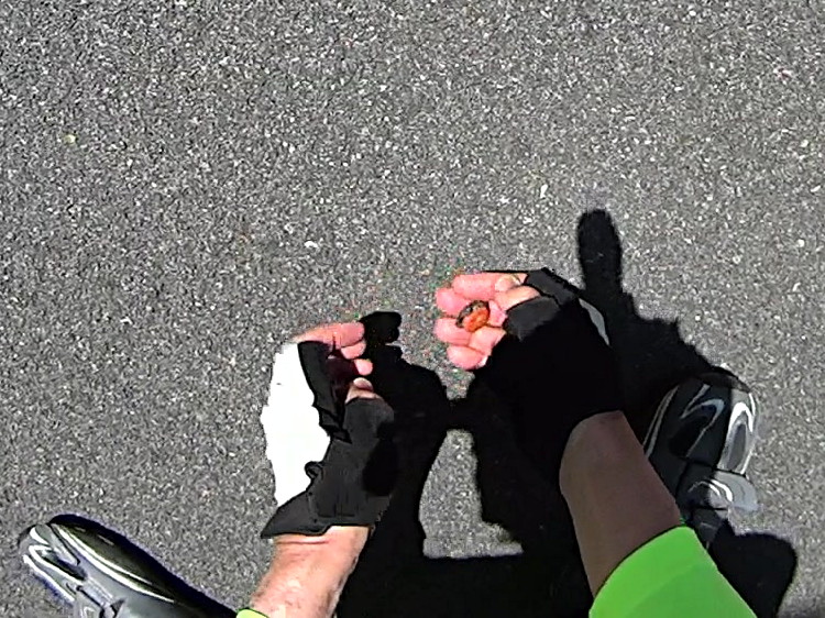
In addition to sawing through the side of the cable ferrule, the front derailleur cable began breaking at the edge of the derailleur arm:
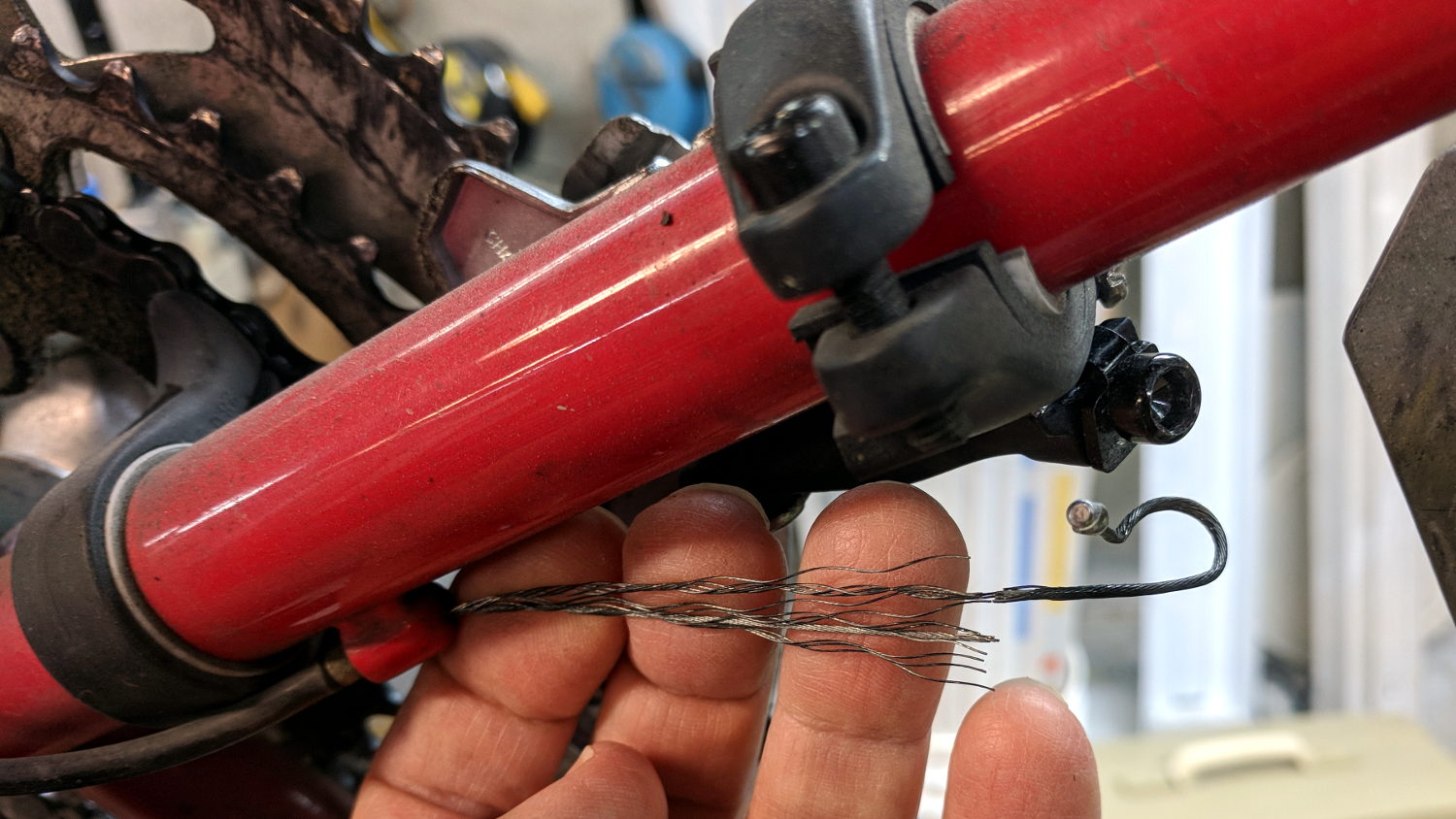
It wouldn’t have survived another ride!
Dan pointed out CNC machined aluminum cable clamps are a thing, but those are sized for larger frame tubes than the 1.0 inch steel used on our Tour Easy ‘bents and, although I’ve shimmed everything else on the frame, I wanted to tweak the cable angle to match the arm on the derailleur.
A bit of OpenSCAD wrangling produces a likely candidate:

That’s a bulked-up revision of the prototype:
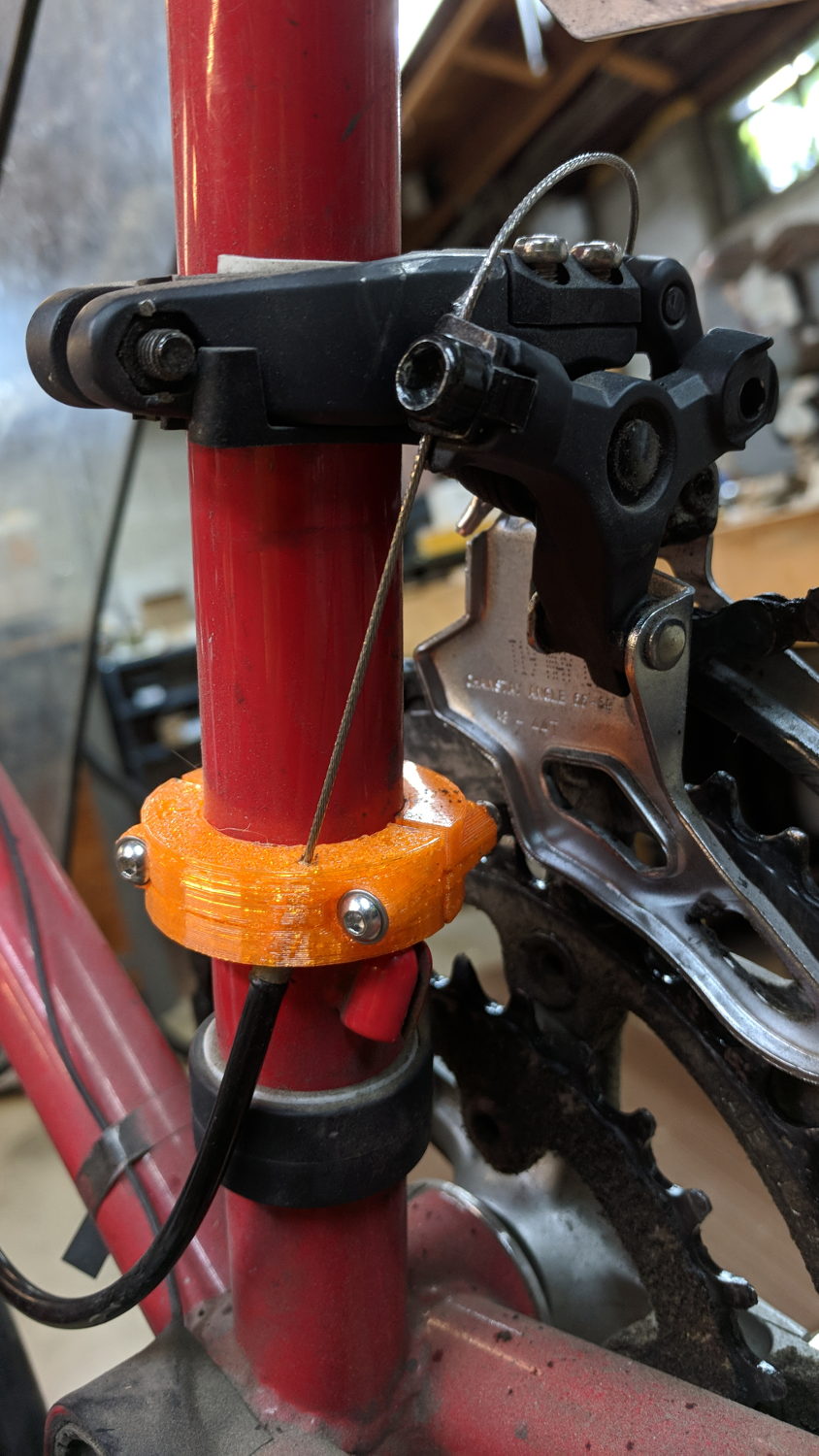
Done up in orange PETG, it demonstrated the idea worked, but two perimeter threads wrapped around 15% infill isn’t quite up to the task. Note the split along the screw on the far half and various irregularities around the ferrule.
The cable angle isn’t quite right, either, as the proper compound angle would, alas, aim the cable into the pedal crank. The bulky bushings get in the way of putting the ferrule where it should be with the screws aligned in a tidy manner, so I must get used to the jaunty angle.
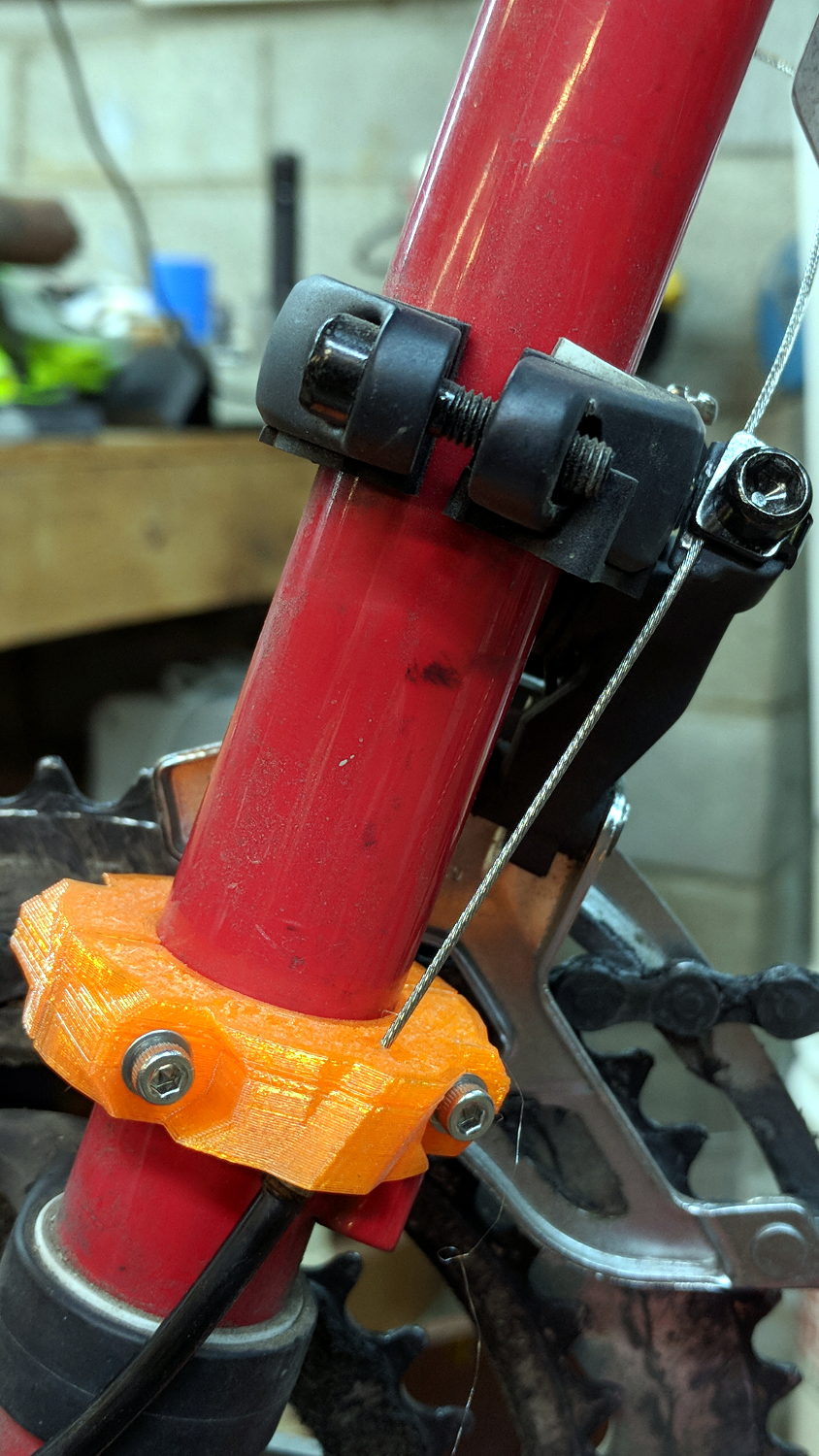
The bulkier version, done with 50% infill and four perimeter threads, has the same tilt angle, but the ferrule sits further from the screws:

The view from the left side shows the cable angles slightly to the rear, but the smaller angle should make it happier:
Probably should have used black PETG. Next time, for sure!
The OpenSCAD source code as a GitHub Gist:
| // Tour Easy Derailleur Cable Clamp | |
| // Ed Nisley KE4ZNU – June 2017 | |
| /* [Build Options] */ | |
| Layout = "Build"; // [Build, Show] | |
| /* [Extrusion] */ | |
| ThreadThick = 0.25; // [0.20, 0.25] | |
| ThreadWidth = 0.40; // [0.40] | |
| function IntegerMultiple(Size,Unit) = Unit * ceil(Size / Unit); | |
| /* [Hidden] */ | |
| Protrusion = 0.01; // [0.01, 0.1] | |
| HoleWindage = 0.2; | |
| ID = 0; | |
| OD = 1; | |
| LENGTH = 2; | |
| /* [Cable Clamp] */ | |
| FrameOD = 25.7; // Tour Easy has hard inch tubing + paint | |
| Ferrule = [1.5,5.1,12.0]; // cable ferrule | |
| EntryPoint = [0,13,60]; // cable entry to derailleur, +Y to rear of bike | |
| CableTilt = -20; // tilt from parallel to frame tube | |
| CableTheta = 0; // rotation around clamp from +X axis | |
| /* [Screws and Inserts] */ | |
| ClampScrew = [3.0,5.5,35.0]; // M3 button / socket head cap screw | |
| ClampWasher = [3.7,7.0,0.7]; // M3 washer | |
| ClampNut = [3.0,6.0,4.0]; // M3 nylock nut | |
| /* | |
| ClampScrew = [4.0,7.0,25.0]; // M4 button head cap screw | |
| ClampWasher = [4.5,9.0,0.8]; // M4 washer | |
| ClampNut = [4.0,8.0,5.0]; // M4 nylock nut | |
| */ | |
| NutShift = -0; // slide bushing toward nut for clearance | |
| //- Set clamp ring dimensions | |
| WallThick = 10.0; | |
| BushingSides = 8; | |
| Bushing = [ClampScrew[ID], | |
| // ClampWasher[OD]/cos(180/8) + 4*ThreadWidth, | |
| Ferrule[LENGTH]/cos(180/BushingSides), | |
| ClampScrew[LENGTH] – 2*ClampWasher[LENGTH] – ClampNut[LENGTH]]; | |
| Ring = [FrameOD + HoleWindage,FrameOD + 2*WallThick,Ferrule[LENGTH]]; | |
| ClampScrewOC = IntegerMultiple(FrameOD + ClampWasher[OD],1); | |
| echo(str(" screw OC: ",ClampScrewOC)); | |
| ClampKerf = 0.75; // kerf between separated halves | |
| NumSides = 8*4; | |
| //- Adjust hole diameter to make the size come out right | |
| module PolyCyl(Dia,Height,ForceSides=0) { // based on nophead's polyholes | |
| Sides = (ForceSides != 0) ? ForceSides : (ceil(Dia) + 2); | |
| FixDia = Dia / cos(180/Sides); | |
| cylinder(r=(FixDia + HoleWindage)/2,h=Height,$fn=Sides); | |
| } | |
| // Construct things | |
| module ClampRing() { | |
| difference() { | |
| union() { | |
| cylinder(d=Ring[OD],h=Ring[LENGTH],$fn=NumSides); // basic ring | |
| for (j=[-1,1]) // screw bushings | |
| translate([Bushing[LENGTH]/2 + NutShift,j*ClampScrewOC/2,Ring[LENGTH]/2]) | |
| rotate([0,-90,0]) rotate(180/BushingSides) | |
| cylinder(d=Bushing[OD],h=Bushing[LENGTH],$fn=BushingSides); | |
| intersection() { | |
| rotate([CableTilt,0,CableTheta]) // reinforce cable ferrule | |
| translate([(Ring[ID] + Ring[OD])/4,0,Ferrule[LENGTH]/2]) | |
| rotate(180/8) | |
| cylinder(d=3*Ferrule[OD] + 0*ThreadWidth,2*Ferrule[LENGTH],center=true,$fn=8); | |
| cylinder(d=2*Ring[OD],h=Ring[LENGTH],$fn=NumSides); // basic ring | |
| } | |
| } | |
| translate([0,0,-Protrusion]) // frame tube | |
| cylinder(d=Ring[ID],h=Ring[LENGTH] + 2*Protrusion,$fn=NumSides); | |
| rotate([CableTilt,0,CableTheta]) // cable ferrule | |
| translate([(Ring[ID] + Ring[OD])/4,0,-0.25*Ferrule[LENGTH]]) { | |
| rotate(180/8) | |
| PolyCyl(Ferrule[OD],Ferrule[LENGTH],8); | |
| rotate(-22.5) | |
| PolyCyl(Ferrule[ID],2*Ferrule[LENGTH],4); | |
| } | |
| for (j=[-1,1]) // screw holes | |
| translate([Ring[OD]/2,j*ClampScrewOC/2,Ring[LENGTH]/2]) | |
| rotate([0,-90,0]) rotate(180/6) | |
| PolyCyl(Bushing[ID],Ring[OD],6); | |
| for (i=[-1,1], j=[-1,1]) // screw & nut seats | |
| translate([i*(Bushing[LENGTH]/2) + NutShift,j*ClampScrewOC/2,Ring[LENGTH]/2]) | |
| rotate([0,i*90,0]) rotate(180/BushingSides) | |
| cylinder(d=Bushing[OD],h=Bushing[LENGTH],$fn=BushingSides); | |
| translate([0,0,Ring[LENGTH]/2]) // slice it apart | |
| cube([ClampKerf,2*Ring[OD],2*Ring[LENGTH]],center=true); | |
| } | |
| } | |
| //- Build things | |
| if (Layout == "Show") { | |
| translate(EntryPoint) | |
| cube(1,center=true); | |
| ClampRing(); | |
| } | |
| if (Layout == "Build") { | |
| ClampRing(); | |
| } |