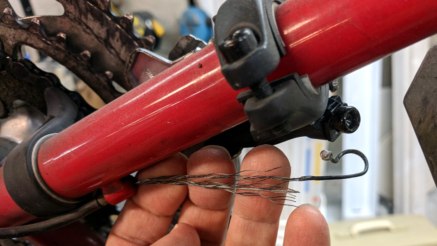
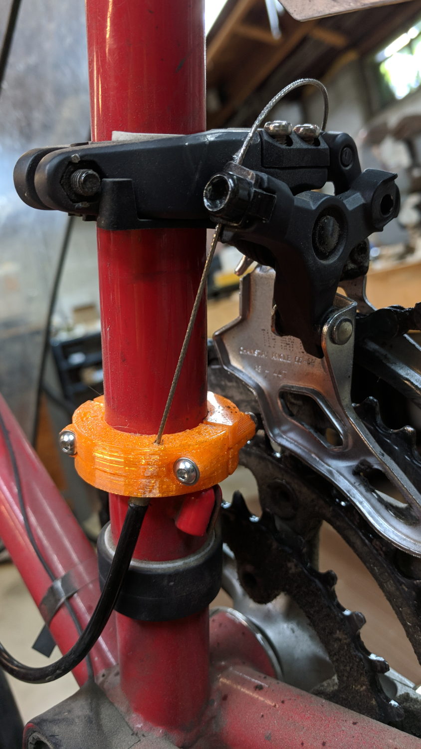
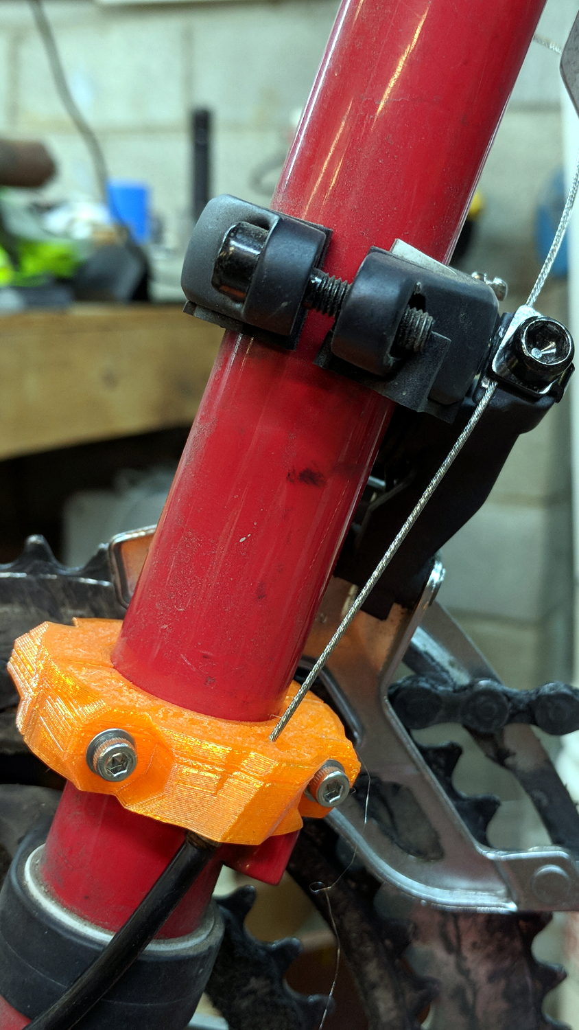
The Smell of Molten Projects in the Morning

Ed Nisley's Blog: Shop notes, electronics, firmware, machinery, 3D printing, laser cuttery, and curiosities. Contents: 100% human thinking, 0% AI slop.

Tag: Improvements

Making the world a better place, one piece at a time

  • Sena PS410 Serial Server: Shelf with Calculations

    A crude shelf bandsawed from a plank moves the Sena PS410 serial server and an old Ethernet switch off the bench:

    Serial server shelf - front
    Serial server shelf – front

    The brackets holding it to the studs came from a 2×4 inch scrap:

    Serial server shelf - rear
    Serial server shelf – rear

    Obviously, the Basement Laboratory lacks stylin’ home decor.

    None of which would be worth mentioning, except for some Shop Calculations scrawled on the 2×4:

    Wood shop calculations
    Wood shop calculations

    It’s in my handwriting, although whatever it related to is long gone.

    Trigonometry FTW!

  • Snowblower Muffler Bracket

    After three years, the bracket locking the snowblower’s muffler bolts broke, but this time I saw the bolt pop out of the muffler, fall to the driveway, and lie there sizzling in the slush. I tightened the remaining bolt and completed the mission.

    The OEM bracket was thin sheet metal and broke across one bolt hole under the head. I sawed a rectangle out of a defunct PC case, then drilled clearance holes:

    Snowblower muffler - drilling bracket
    Snowblower muffler – drilling bracket

    Bending two corners upward locks the bolt heads in position. I started the bends by clamping the bracket in the bench vise and whacking the corners, then finishing the job with a drift punch after installing it:

    Snowblower muffler installed
    Snowblower muffler installed

    Of course, I renewed the Never-Seez on the bolt threads; they obviously weren’t corroded in place!

    For whatever it’s worth, the many spot welds joining the top bracket to the muffler are doing just fine.

  • MPCNC: Linear Bearing Pen Holder

    The simplest way to push a pen (or similar thing) downward with constant force may be to hold it in a linear bearing with a weight on it, so I gimmicked up a proof-of-concept. The general idea is to mount the pen so its axis coincides with the DW660 spindle, so as to have the nib trace the same path:

    DW660 Pen Holder - unweighted
    DW660 Pen Holder – unweighted

    The puck mimics the shape of the DW660 snout closely enough to satisfy the MPCNC’s tool holder:

    DW660 Pen Holder - Slic3r
    DW660 Pen Holder – Slic3r

    The pen holder suffers from thin walls constrained by the 10 mm (-ish) pen OD and the 12 mm linear bearing ID, to the extent the slight infill variations produced by the tapered pen outline change the OD. A flock of 16 mm bearings, en route around the planet even as I type, should provide more meat.

    In any event, 3D printing isn’t noted for its perfect surface finish, so I applied an epoxy layer and rotated the holder as it cured:

    DW660 Pen Holder - epoxy coating
    DW660 Pen Holder – epoxy coating

    After letting it cure overnight, I ran a lathe tool along the length to knock down the high spots and set the OD to 11.9+ mm. Although the result turns out to be a surprisingly nice fit in the bearing, there’s no way epoxy can sustain the surface load required for the usual precision steel-on-steel fit.

    A plastic pen in a plastic holder weighs 8.3 g, which isn’t quite enough to put any force on the paper. Copper weighs 9 g/cm³ = 9 mg/mm³ and 10 AWG wire is 2.54 mm OD = 5 mm², so it’s 45 mg/mm: to get 20 g, chop off 450 mm of wire.

    I chopped off a bit more than that, straightened it, annealed it, and wound it around a random contestant from the Bucket o’ Sticks with an OD just over the pen OD:

    DW660 Pen Holder - copper weight forming
    DW660 Pen Holder – copper weight forming

    The helix is 13.5 mm down the middle of the turns and 14 turns long (trimmed of the tail going into the chuck and fudging the tail sticking out as a partial turn), so it’s 593 mm long and should weigh 26.7 g. It actually weighs 27.6 g: close enough.

    Which is enough to overcome stiction due to the holder’s surface roughness, but the mediocre epoxy-on-balls fit allows the pen point to wander a bit too much for good results.

    The prospect of poking precise holes into 16 mm drill rod seems daunting, but, based on what I see here, it will produce much better results: rapid prototyping FTW!

    The OpenSCAD source code as a GitHub Gist:

    // MPCNC Pen Holder for DW660 Mount
    // Ed Nisley KE4ZNU – 2018-03-05
    Layout = "Build"; // Build, Show
    // Puck, MountBase, BuildBase
    // Pen, PenAdapter, BuildAdapter
    /* [Extrusion] */
    ThreadThick = 0.25; // [0.20, 0.25]
    ThreadWidth = 0.40; // [0.40]
    /* [Hidden] */
    Protrusion = 0.1; // [0.01, 0.1]
    HoleWindage = 0.2;
    inch = 25.4;
    function IntegerMultiple(Size,Unit) = Unit * ceil(Size / Unit);
    ID = 0;
    OD = 1;
    LENGTH = 2;
    //- Adjust hole diameter to make the size come out right
    module PolyCyl(Dia,Height,ForceSides=0) { // based on nophead's polyholes
    Sides = (ForceSides != 0) ? ForceSides : (ceil(Dia) + 2);
    FixDia = Dia / cos(180/Sides);
    cylinder(r=(FixDia + HoleWindage)/2,h=Height,$fn=Sides);
    }
    //- Dimensions
    WallThick = 3.0; // minimum thickness / width
    Screw = [3.0,7.0,25.0]; // holding it all together, OD = washer
    Insert = [3.0,4.4,4.5]; // brass insert
    Bearing = [12.0,21.0,30.0]; // LM12UU bearing body, ID = rod OD
    PenTravel = 5.0; // vertical pen travel allowance
    NumSides = 8*4; // cylinder facets
    //—–
    // Define shapes
    //– Sakura Micron fiber-point pen
    ExpRP = 0.30; // expand critical sections (by radius)
    //– pen locates in holder against end of outer body
    PenOutline = [
    [0,0], // 0 fiber pen tip
    [0.6/2,0.0],[0.6/2,0.9], // 1 … cylinder
    [1.5/2,0.9],[1.5/2,5.3], // 3 tip surround
    [4.7/2,5.8], // 5 chamfer
    [4.9/2,12.3], // 6 nose
    // [8.0/2,12.3],[8.0/2,13.1], // 7 latch ring
    // [8.05/2,13.1],[8.25/2,30.5], // 9 actual inner body
    [8.4/2 + ExpRP,12.3],[8.4/2 + ExpRP,30.5], // 7 inner body – clear latch ring
    [9.5/2 + ExpRP,30.9], // 9 outer body – location surface!
    [9.8/2 + ExpRP,60.0], // 10 outer body – length > Body
    [7.5/2,60.0], // 11 arbitrary length, much longer than bearing
    [7.5/2,59.0], // 12 end of reservoir
    [0,59.0] // 13 fake reservoir
    ];
    PenNose = PenOutline[6][1];
    PenLocate = PenOutline[9][1];
    // Basic shape of DW660 snout fitting into the holder
    // Lip goes upward to lock into MPCNC mount
    Snout = [44.6,50.0,9.6]; // LENGTH = ID height
    Lip = 4.0; // height of lip at end of snout
    Key = [Snout[ID],25.7,Snout[LENGTH] + Lip]; // rectangular key
    module DW660Puck() {
    cylinder(d=Snout[OD],h=Lip/2,$fn=NumSides);
    translate([0,0,Lip/2])
    cylinder(d1=Snout[OD],d2=Snout[ID],h=Lip/2,$fn=NumSides);
    cylinder(d=Snout[ID],h=Lip + Snout[LENGTH],$fn=NumSides);
    intersection() {
    translate([0,0,0*Lip + Key.z/2])
    cube(Key,center=true);
    cylinder(d=Snout[OD],h=Lip + Key.z,$fn=NumSides);
    }
    }
    module MountBase() {
    difference() {
    DW660Puck();
    translate([0,0,-Protrusion])
    PolyCyl(Bearing[OD],2*Bearing[LENGTH],NumSides);
    }
    }
    //– Sakura drawing pen body & polygon shape
    module Pen() {
    rotate_extrude($fn=NumSides)
    polygon(points=PenOutline);
    polygon(points=PenOutline);
    }
    //– Pen holder
    AdapterRing = [Bearing[ID],Bearing[OD],4.0];
    AdapterOAL = Bearing[LENGTH] + PenTravel + AdapterRing[LENGTH];
    module PenAdapter() {
    difference() {
    union() {
    PolyCyl(Bearing[ID],AdapterOAL,NumSides);
    translate([0,0,AdapterOAL – AdapterRing[LENGTH]])
    cylinder(d=AdapterRing[OD],h=AdapterRing[LENGTH],$fn=NumSides);
    }
    translate([0,0,-(PenNose + Protrusion)])
    Pen();
    }
    }
    //—–
    // Build it
    if (Layout == "Puck")
    DW660Puck();
    if (Layout == "MountBase")
    MountBase();
    if (Layout == "Pen")
    Pen();
    if (Layout == "PenAdapter")
    PenAdapter();
    if (Layout == "Show")
    MountBase();
    if (Layout == "BuildBase" || Layout == "Build")
    translate([0,-Snout[OD]/2,0])
    MountBase();
    if (Layout == "BuildAdapter" || Layout == "Build")
    translate([0,Snout[OD]/2,AdapterOAL])
    rotate([180,0,0])
    PenAdapter();
  • Sena PS410 Serial Server: Capturing HP 54602 Screen Images

    The objective is to capture screen shots from my HP 54602 oscilloscope, now connected to Serial Port 1 of the Sena PS410 serial server.

    Although the scope command language offers a :PRINT? command, it produces output in HP PCL, from which there seems no practical way to get a raster image format like PNG. So this remains an output-only transfer triggered by poking the PRINT SCREEN softkey, after first setting the serial parameters:

    HP 54602 scope serial parameters
    HP 54602 scope serial parameters

    In text:

    • Connect to: HP Plotter
    • Factors: ON
    • Resolution: HIGH
    • Baud rate: 19200 b/s
    • Handshake: XON

    I have no idea what’s inside the serial cable at this late date (see the HP 8591 post for more musings), but the (paper!) manual says:

    For three-wire operation, an XON/XOFF software handshake must be used to handle handshaking between the devices.
    For extended hardwire operation, handshaking may be handled either with XON/XOFF or by manipulating the CTS and RTS lines of the oscilloscope.
    For both three-wire and extended hardwire operation, the DCD and DSR inputs to the oscilloscope must remain high for proper operation.
    With extended hardwire operation, a high on the CTS input allows the oscilloscope to send data and a low on this line disables the oscilloscope data transmission.
    Likewise, a high on the RTS line allows the controller to send data and a low on this line signals a request for the controller to disable data transmission.
    Since three-wire operation has no control over the CTS input, internal pull-up resistors in the oscilloscope ensure that this line remains high for proper three-wire operation.

    Apparently, the DCD, DSR, and CTS inputs have internal pullups.

    Hardware handshakings uses these signals:

    • Pin 4 RTS (Request To Send) is an output from the oscilloscope which can be used to control incoming data flow.
    • Pin 5 CTS (Clear To Send) is an input to the oscilloscope which controls data flow from the oscilloscope.
    • Pin 6 DSR (Data Set Ready) is an input to the oscilloscope which controls data flow from the oscilloscope within two bytes.
    • Pin 8 DCD (Data Carrier Detect) is an input to the oscilloscope which controls data flow from the oscilloscope within two bytes.
    • Pin 20 DTR (Data Terminal Ready) is an output from the oscilloscope which is enabled as long as the oscilloscope is turned on.

    The scope wiggles them thusly:

    The TD (Transmit Data) line from the oscilloscope must connect to the RD (Receive Data) line on the controller. Likewise, the RD line from the oscilloscope must connect to the TD line on the controller.
    The RTS (Request To Send) line is an output from the oscilloscope which can be used to control incoming data flow. A high on the RTS line allows the controller to send data, and a low on this line signals a request for the controller to disable data transmission.
    The CTS (Clear To Send), DSR (Data Set Ready), and DCD (Data Carrier Detect) lines are inputs to the oscilloscope which control data flow from the oscilloscope (Pin 2). Internal pull-up resistors in the oscilloscope assure the DCD and DSR lines remain high when they are not connected.
    If DCD or DSR are connected to the controller, the controller must keep these lines and the CTS line high to enable the oscilloscope to send data to the controller. A low on any one of these lines will disable the oscilloscope data transmission.
    Dropping the CTS line low during data transmission will stop oscilloscope data transmission immediately.
    Dropping either the DSR or DCD line low during data transmission will stop oscilloscope data transmission, but as many as two additional bytes may be transmitted from the oscilloscope.

    The “as many as two additional bytes may be transmitted” suggests the same problem as with the HP 8591 spectrum analyzer at 19200 b/s, wherein it seems to overrun the PS410 input despite the flickering CTS control line.

    I set up hardware handshaking in the PS410 and discovered the CTS line flickers as it does with the 8591, but the transfer complete without overruns. Perhaps the 8591 sends more than however many characters the PS410 can handle after calling for a pause?

    The Kermit setup points to Serial Port 1 on the PS410:

    set host 192.168.1.40 7001 /raw-socket
    set modem none
    

    And then the rest of the script Just Works:

    Calibrator waveform
    Calibrator waveform

    The Kermit script as a GitHub Gist:

    #!/usr/bin/kermit +
    # Fetches screen shot from HP54602B oscilloscope
    # Presumes it's set up for plotter output…
    # Converts HPGL to PNG image
    set host 192.168.1.40 7001 /raw-socket
    set modem none
    # Make sure we have a param
    if not defined \%1 ask \%1 {File name? }
    set input echo off
    set input buffer-length 200000
    # Wait for PRINT button to send the plot
    echo Set HP54602B for HP Plotter, FACTORS ON, 19200, XON
    echo Press PRINT SCREEN button on HP54602B…
    log session "\%1.hgl"
    # Factors On
    input 480 \x03
    close session
    close
    echo Converting HPGL in
    echo –\%1.hgl
    echo to PNG in
    echo –\%1.png
    # Factors Off
    #run hp2xx -q -m png -a 1.762 -h 91 -c 14 "\%1.hgl"
    #run mogrify -density 300 -resize 200% "\%1.png"
    # Factors On
    run sed '/lb/!d' "\%1.hgl" > "\%1-1.hgl"
    #run hp2xx -q -m eps -r 270 -a 0.447 -d 300 -w 130 -c 14 -p 34 -f "\%1.eps" "\%1-1.hgl"
    run hp2xx -q -e 40 -m eps -r 270 -a 0.447 -c 14 -f "\%1.eps" "\%1-1.hgl"
    run rm "\%1-1.hgl"
    #run convert -density 300 -resize 675×452+2+2 "\%1.eps" "\%1.png"
    run convert "\%1.eps" -alpha off -resize 675×452 "\%1.png"
    echo Finished!
    exit 0
    view raw gethp54602 hosted with ❤ by GitHub


  • Sena PS410 Serial Server: Capturing HP 8591 Screen Images

    The objective is to capture screen shots from the HP 8591 spectrum analyzer, now connected to Serial Port 2 of the Sena PS410 serial server.

    My analyzer is an old one with a 3322A serial number, so its Opt 023 came with a genuine DB-25 female connector, not the DE-9 male connector described in the HP doc for the later Op 043 hardware. With that in mind, the HP doc says the spectrum analyzer supports only hardware handshaking:

    • Baud rate 300 to 57,000 baud.
    • 8 bits per character.
    • 1 stop bit.
    • No parity.
    • Software handshake – none.
    • Xon/Xoff and ENQ/ACK not supported by the spectrum analyzer.

    The manual enumerates the handshaking lines:

    • Request to send (RTS) – Output signal indicates that the spectrum analyzer is ready to communicate. This line is true at power-up and stays true while power is on.
    • Clear to send (CTS) – Input signal indicates that the external controller is ready to receive data.
    • Data terminal ready (DTR) – Output signal from the spectrum analyzer. When the input buffer is full, this line goes false.
    • Data set ready (DSR) – Is not available.
    • Data carrier detect (DCD) – Input to the spectrum analyzer. If DCD is true, the spectrum analyzer will receive data from the controller. If false, no data will be input. The data will be ignored.

    Furthermore, it is written:

    The spectrum analyzer checks its CTS input before transmitting data to the computer. If the CTS line is false, the spectrum analyzer will not transmit data. The spectrum analyzer transmits data when the CTS line is true.

    The spectrum analyzer sets the DTR line (PC CTS) false when its input buffer is full.

    They offer several wiring diagrams, none of which correspond to the hardware on my bench, but swapping the “Personal Computer” and “Analyzer” headings on this diagram seems close to reality:

    HP 8591 - RS232 DB25 to DE9 wiring diagram
    HP 8591 – RS232 DB25 to DE9 wiring diagram


    On the other end of the cable, the PS410 does “hardware flow control using RTS/CTS”. They also offer a diagram:

    Sena PS410 - RS232 wiring diagram
    Sena PS410 – RS232 wiring diagram

    So I rewired the cable thusly:

    HP 8591 vs Sena PS410 - RS232 cable diagram
    HP 8591 vs Sena PS410 – RS232 cable diagram

    Pin 1 on the 8591 interface connects to both frame ground and signal ground and, back when I first made this cable, many years ago, I had wired it to the shield of the cable and thence to the DE9 shell. Alas, the PS410 took offense; for reasons I don’t understand, a shell-to-ground connection ignites a ferrite bead on the PS410’s PCB.

    With the rewired cable in hand, the PS410 serial port setup looks like this:

    Port 2 - 8591 serial config
    Port 2 – 8591 serial config

    The PS410 apparently wiggles its RTS output after every byte it receives, because the CTS input at the 8591 turns into a blur during screen captures. This seems unaffected by the Inter character time-out setting and doesn’t (seem to) produce any problems, so it’s like that and that’s the way it is.

    Using 9600 b/s isn’t as slow as you might think. The HP manual  notes:

    Some of the programs in this manual use 1200 baud for proper operation. If your system uses the RS-232 handshake lines, you can use 9600 baud for all of the programs.

    I tried 19200 b/s and got mysterious errors that resemble overruns, which suggests the 8591 ignores the PS410’s flickering RTS output. The screen dumps require only a few seconds, so it’s not a big deal, although timing issues have a way of resurfacing at the most inopportune, uh, times.

    Kermit knows how to handle network sockets and suchlike, so aiming it at the spectrum analyzer is a one-liner:

    set host 192.168.1.40 7002 /raw-socket
    set modem none
    

    The /raw-socket disables Kermit’s default Telnet interface, preventing it from squirting IAC + BRK characters when closing the session; I think that’s what happens, but I don’t use Telnet enough to know better. As you might expect, the 8591 deals poorly with characters outside its lexicon.

    It’s not obvious set modem none does anything in this context, but it seems reasonable.

    Then the rest of the script Just Works:

    FM 104.7 MHz peak hold
    FM 104.7 MHz peak hold

    Which is the peak-hold spectrum of a local FM station, as received through an amateur radio HT rubber duck antenna.

    The Kermit source code as a GitHub Gist:

    #!/usr/bin/kermit +
    # Fetches screen shot from HP8591E spectrum analyzer
    # Presumes it's set up for plotter output…
    # Converts HPGL to PNG image
    # use raw-socket to disable telnet termination chars
    set host 192.168.1.40 7002 /raw-socket
    set modem none
    # Make sure we have a param
    if not defined \%1 ask \%1 {File name? }
    set input echo off
    set input buffer-length 200000
    # Tell it what size to plot
    echo Triggering plot output…
    output plot 0,0,60000,40000;
    log session "\%1.hgl"
    # Wait for end of data stream
    input 400 SP;
    echo … HPGL data captured
    close session
    close
    echo Converting HPGL in
    echo –\%1.hgl
    echo to PNG in
    echo –\%1.png
    run hp2xx -q -m png -c 1436 "\%1.hgl"
    echo Cropping and resizing
    #run mogrify -crop "515×395+0+0!" "\%1.png"
    run mogrify -density 300 -resize 200% "\%1.png"
    echo Finished!
    exit 0
    view raw gethp8591 hosted with ❤ by GitHub
  • Sena PS410 Serial Server: socat and minicom

    Per the socat man page:  “Socat … establishes two bidirectional byte streams and transfers data between them”. Using it to connect minicom to the HP Z3801 (PDF user manual) GPS receiver’s serial port on the PS410 serial server goes like this:

    socat pty,link=/tmp/z3801 tcp:192.168.1.40:7003 &
    

    The 7003 designates the network port corresponding to serial port 3 on the PS410. The PS410 lets you give its ports any numbers you like, but that way lies madness.

    You may want to run socat in a separate terminal window for easy monitoring (use -d -d for more details) and restarting. The PS410 closes all its network connections when updating any configuration values, pushing any ongoing conversations off the rails. Of course, one doesn’t update the configuration very often after getting it right.

    It produces a device with permissions just for you:

    lrwxrwxrwx 1 ed ed 10 Mar 17 18:45 z3801 -> /dev/pts/2
    

    Whereupon you aim minicom (or whatever you like) at the device:

    minicom -D /tmp/z3801
    

    And It Just Works.

    The PS410 serial port configuration:

    Port 3 - Z3801 serial config
    Port 3 – Z3801 serial config

    The default Z3801 serial port setup seems to be 19200, 7 data, odd parity. I vaguely recall some serial port hackage a long time ago, with the details buried in my paper (!) notes.

    Leaving the Inter Character Timeout at the default 0 creates a blizzard of network activity. Setting it to 10 ms produces slight delays during the full-screen (on an 80 character x 24 line green screen monitor, anyway) status display:

    Z3801 system status
    Z3801 system status

    I inadvertently turned off the UPS powering the thing and the double-oven clock oscillator takes days to restabilize; the Holdover Uncertainty has been dropping slowly ever since.

    Verily, it is written that a man with two clocks never knows what time it is. When one of them is a Z3801, the man has no doubt which clock is correct.

  • MPCNC: USB Camera Alignment

    Adding a lock screw to the camera mount stabilized the camera-to-spindle offset enough to make calibration meaningful. Mark the spot directly under the camera:

    bCNC - Camera - hot glue align
    bCNC – Camera – hot glue align

    Then mark the spot directly under the spindle, perhaps by poking a small cutter into the tape, measure the XY distances between the two center points, and use bCNC’s camera registration process to set the camera offset.

    With those numbers in place, switching to the tool view (the green button with the end mill to the right in the ribbon bar) puts the camera at the spindle location:

    bCNC - Spindle - hot glue align
    bCNC – Spindle – hot glue align

    The view from outside shows the relation between those two pieces of tape:

    MPCNC - USB camera-to-spindle alignment
    MPCNC – USB camera-to-spindle alignment

    Now I can align the camera view to a fixture position and be (reasonably) sure the spindle will automagically align to the same XY coordinate when I switch to the “tool” view. Seems to work well in preliminary tests, anyhow.