Ed Nisley's Blog: Shop notes, electronics, firmware, machinery, 3D printing, laser cuttery, and curiosities. Contents: 100% human thinking, 0% AI slop.
Tag: Improvements
Making the world a better place, one piece at a time
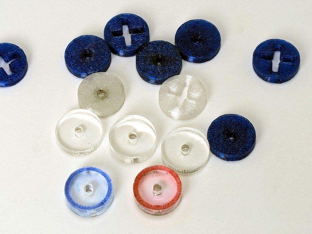
So the engraved ring on the two in the front row carries a cheerful Sharpie color to make them stand out. I wanted to use fluorescent acrylic, but I don’t have any 4 mm sheets and stacking a pair of 3 mm sheets → 6 mm will be too thick for the pencil tip.
What looks like dirt on the red guide comes from internal reflections or the lack thereof: it’s perfectly transparent in person, honest.
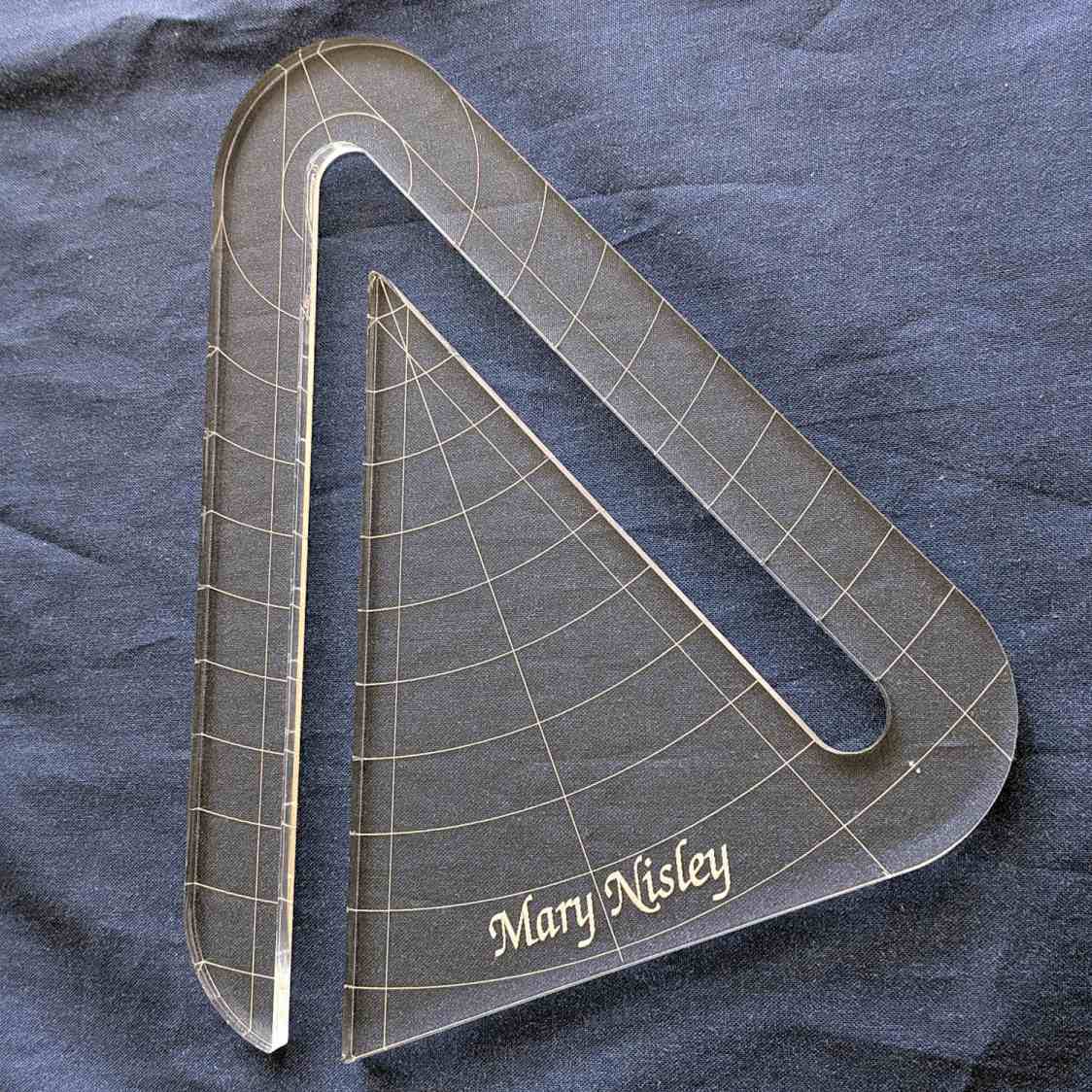
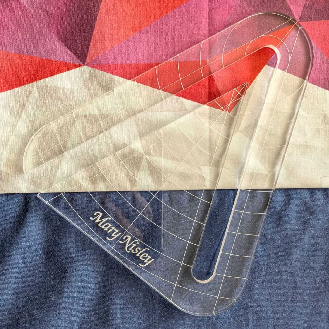
Mary’s current quilt project has a corner design with an essentially infinite number of 45° triangles, which another custom ruler will simplify:
45° Quilting Ruler – finished
That’s the end result of several iterations, proceeding from doodles to sketches to increasingly accurate laser-cut prototypes:
45° Quilting Ruler – prototypes
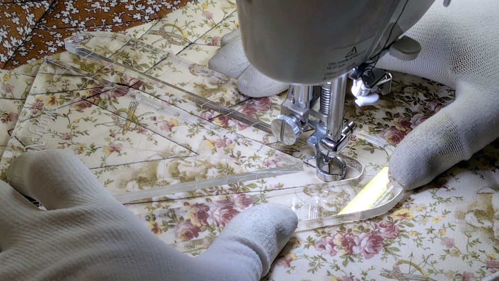
A “ruler” in quilting parlance is a thing guiding the sewing machine’s “ruler foot” across the fabric (or, for sit-down machines, the fabric under the foot) in specific directions:
45° Quilting Ruler – in use
That’s a practice quilt on scrap fabric: quilters need prototypes, too!
The foot is 0.5 inch OD, within a reasonable tolerance, which accounts for the slot width in the ruler. It’s also intended to run against 1/4 inch thick rulers, which accounts for the thickness of that slab of acrylic.
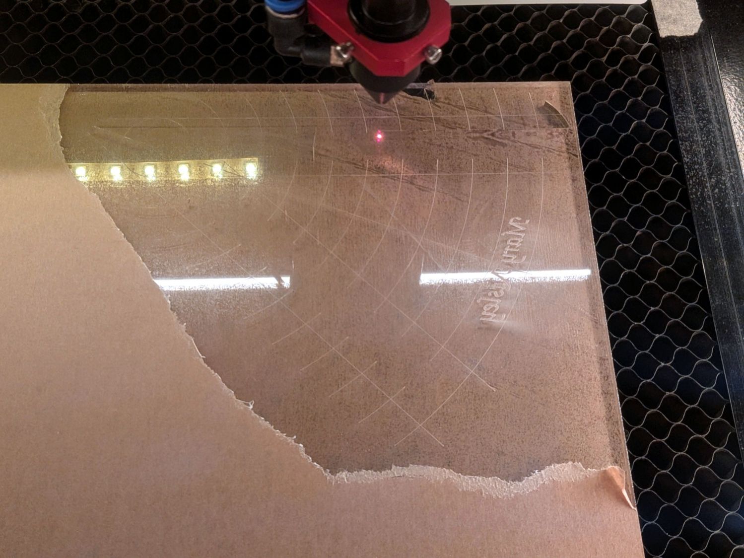
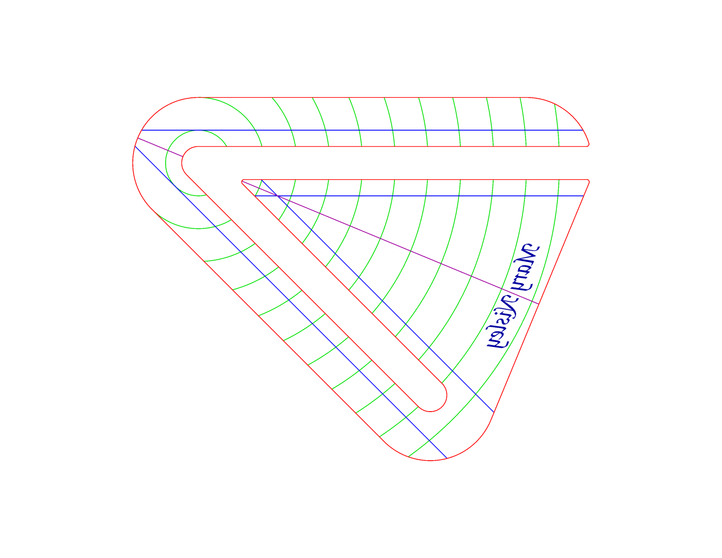
The engraved lines & arcs are on the bottom of the ruler to eliminate parallax errors against the fabric, so the bottom is upward and the text is mirrored for the laser:
45° Quilting Ruler – cutting
Although fluorescent green acrylic may have higher visibility, clear seems adequate for the fabric in question:
45° Quilting Ruler – colored fabric
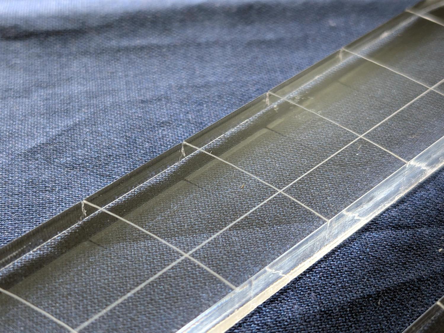
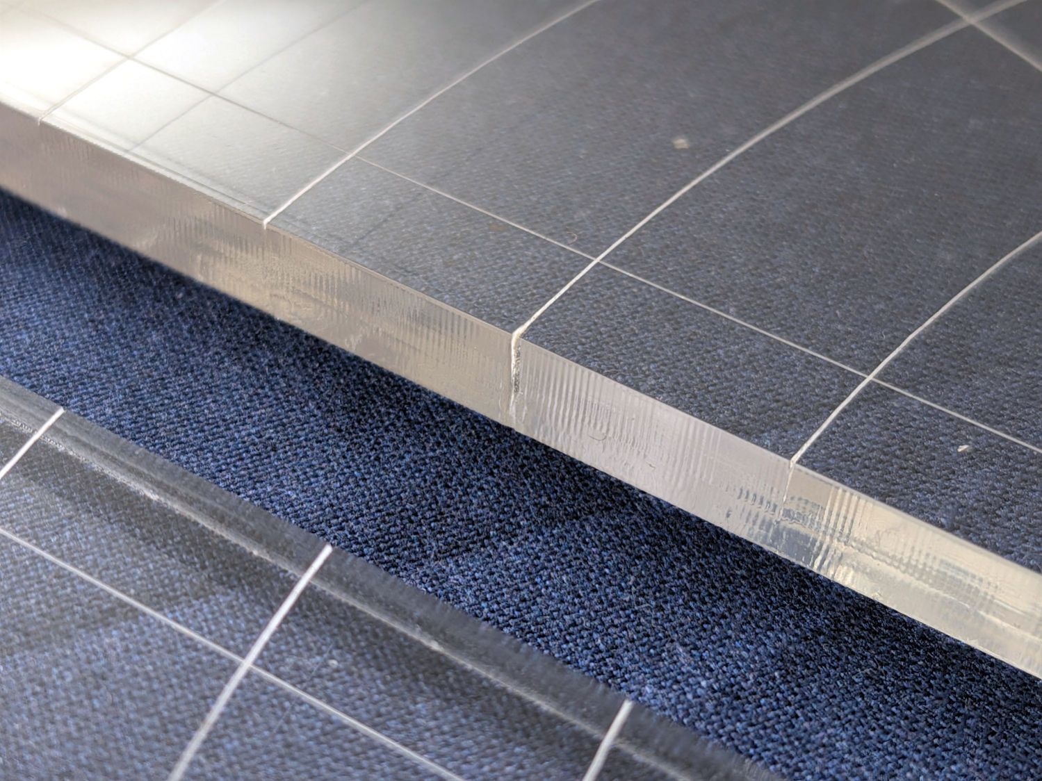
I very carefully trimmed the arcs against the ruler outline using LightBurn’s Cut Shapes, which turned out to be a Bad Idea™, because the high-current pulse as the laser fires causes a visible puncture wound at the still-to-be-cut edge:
45° Quilting Ruler – edge damage
Those are not straight lines and the plastic isn’t bent!
A closer look:
45° Quilting Ruler – edge damage – detail
The arcs without wounds started from their other end and stopped at the edge, which is perfectly fine.
The wounds are unsightly, not structural, but the next time around I’ll extend the markings a millimeter beyond the edges into the scrap material.
The overall design looks busier than it is, because I put different features on different layers in case they needed different settings:
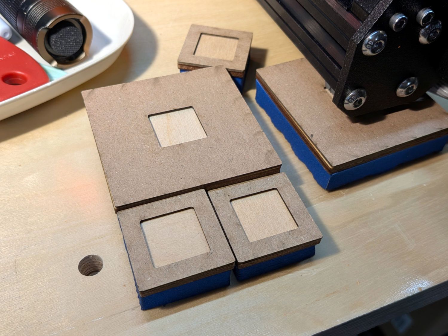
The latches holding the side cover of the portable generator in place work well enough that I never tighten the cover screws, but sometimes one will vibrate itself into place and require less than one turn of a screwdriver to release. Given that I put a knob on the air filter screw, a pair of knobs on the side cover screws makes sense:
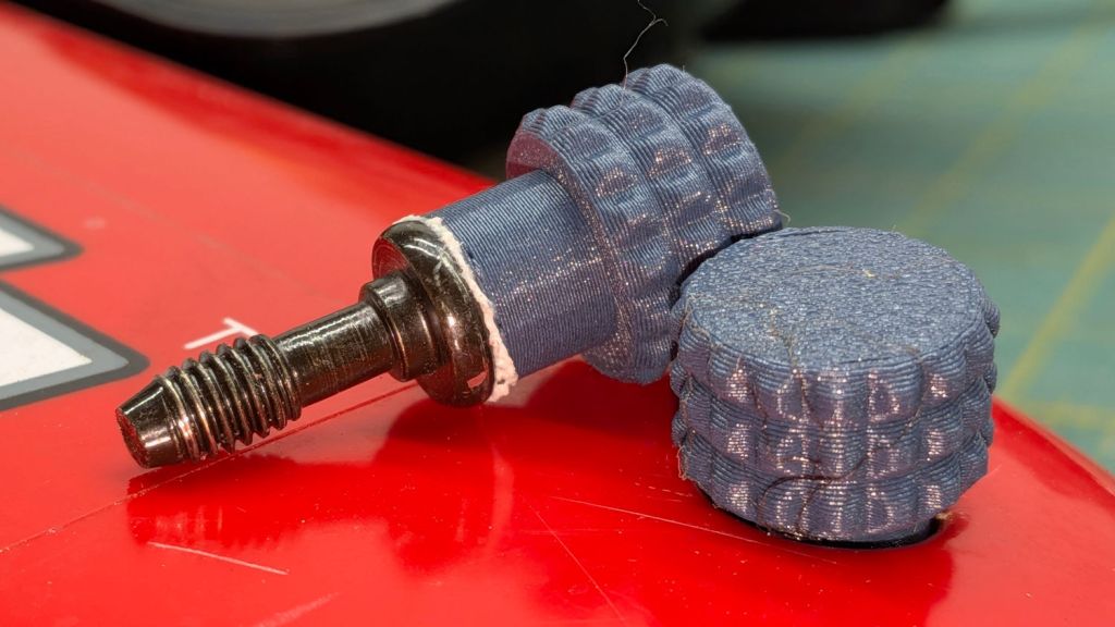
Generator Cover Screw Knob – installed
Those are custom screws! The narrow neck keeps them captive in the cover, which is a Good Thing™.
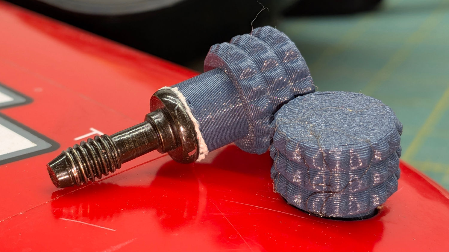
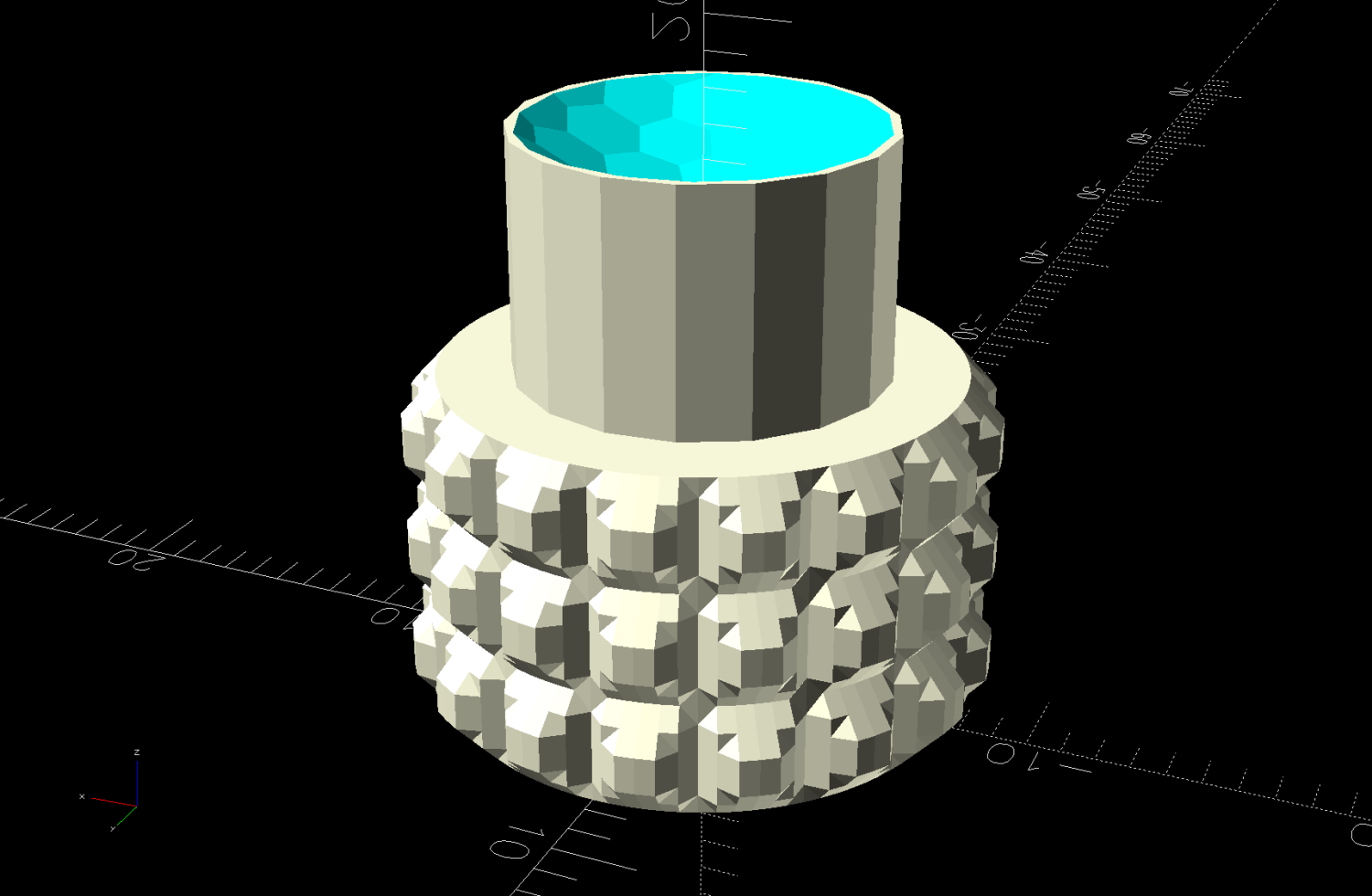
These knobs obviously descend from the air filter knob, with less knurling and a short shaft to clear the recess in the cover:
Generator Cover Screw Knob – solid model
Unlike the air filter knob, the double-sided tape gluing these to their screws isn’t continually compressed, so the knobs may eventually shake off. Should that happen, I’ll deploy epoxy.
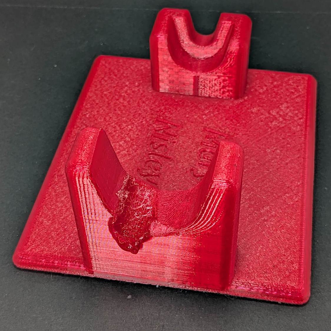
The 3D printed Clover Mini-Iron holder served well over the last decade (!), even after one of Mary’s buddies misplaced the iron during a quilting bee:
Clover MCI-900 Mini Iron holder – melted
She asked for a new holder that put the iron at a higher angle for easier gripping, which required only slight tinkering to boot the OpenSCAD code into the current decade:
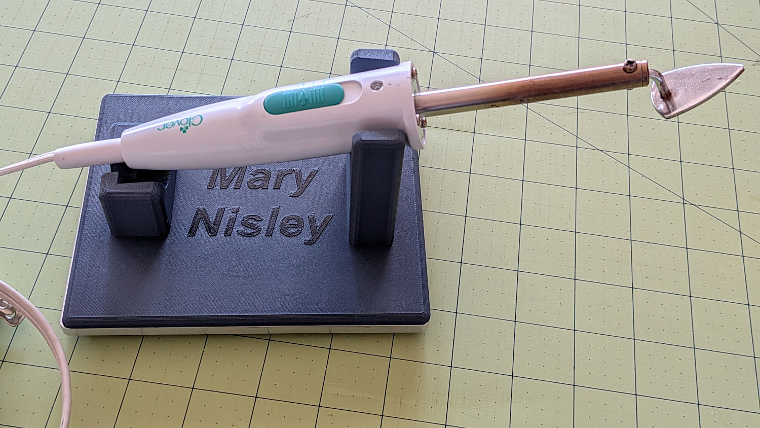
Clover MCI-900 Mini Iron holder – higher angle
The letters stand one layer proud of the surface just to see what that looked like. I think it’s a nice touch.
The alert reader will note the cord end isn’t quite snugged into its recess. In normal use, the cord hangs over the edge of the sewing table and pulls the iron into place.
I embiggened the base to fit an aluminum plate from the stockpile, because that same cord tends to pull the holder around on the table. The plate puts enough weight on the silicone rubber feet to hold it firmly in place.
A layer of good double-stick tape strips bonds the aluminum plate to the PETG iron holder, after I once again discovered that craft adhesive sheets do not bond to PETG.
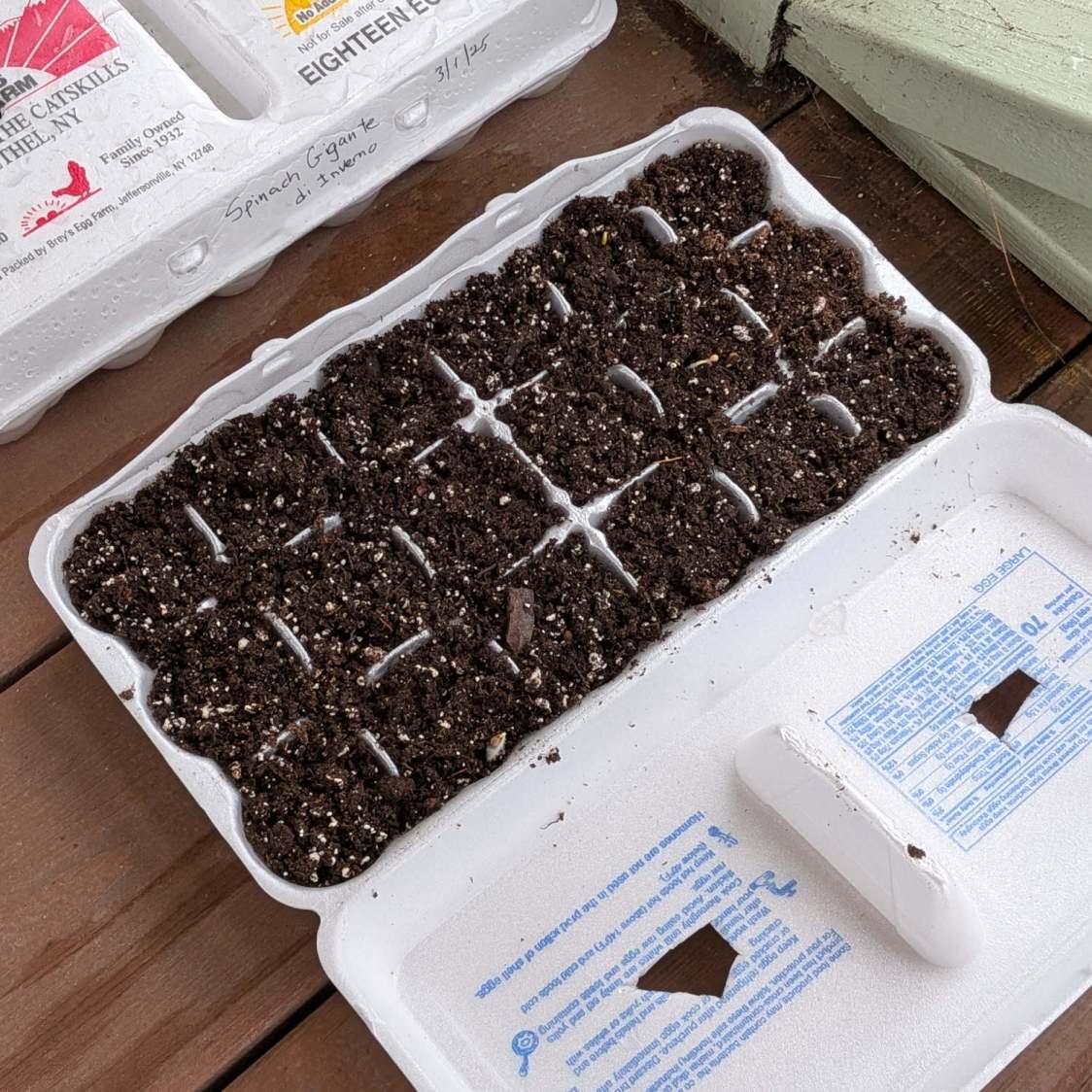
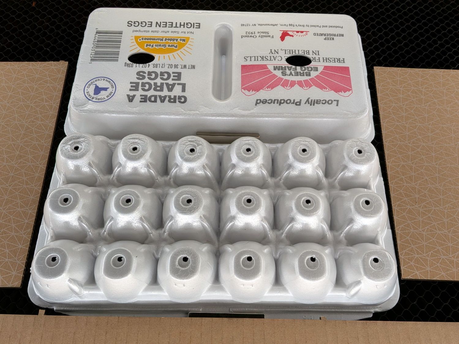
Mary has been using Styrofoam egg cartons to sprout seeds for this year’s garden veggies:
Egg carton sprouter – hand cut
I looked at those artisanal holes and offered to make sprouters with precisely calibrated laser-cut holes.
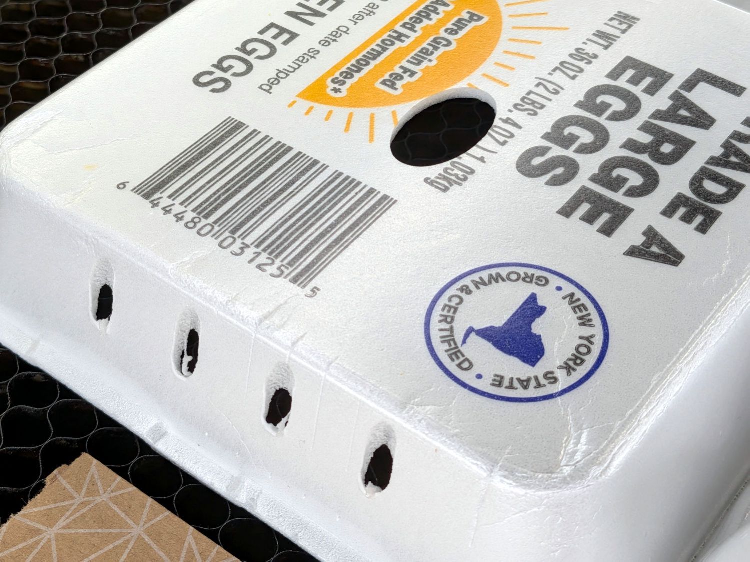
After the laughter died down, this happened:
Egg carton sprouter – lid detail
Each egg compartment has a drainage hole in the bottom:
Egg carton sprouter – on platform
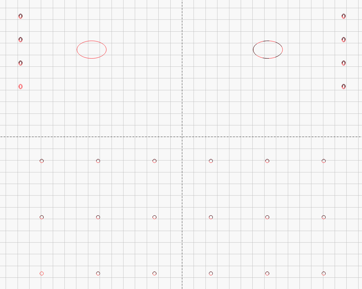
The LightBurn layout has four shapes in three virtual arrays:
Drain holes: 3 mm circle, 6×3 array
Top vents: 25×15 mm oval, 2×1 array
Side vents: concentric 3×4 & 2×3 mm ovals, 2×4 array
Which looks like this:
Egg Carton Sprouter – LightBurn layout
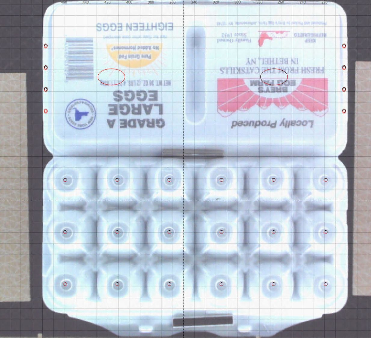
Because this isn’t a high-precision operation, I align the patterns to the carton using the camera:
Egg Carton Sprouter – LightBurn camera alignment
The two halves of the unfolded carton aren’t the same height, which means the top and bottom patterns have different focus levels and must be cut in two operations.


