Ed Nisley's Blog: Shop notes, electronics, firmware, machinery, 3D printing, laser cuttery, and curiosities. Contents: 100% human thinking, 0% AI slop.
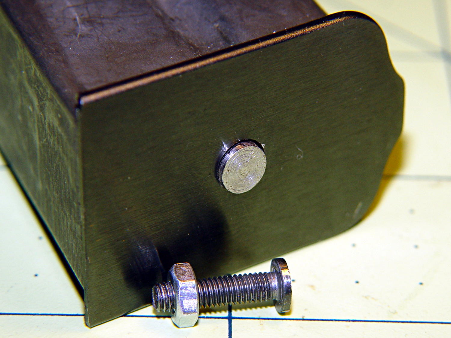
Drill 3 mm hole in the center of the inner plate boss
Wire-brush the plate to remove the black coating
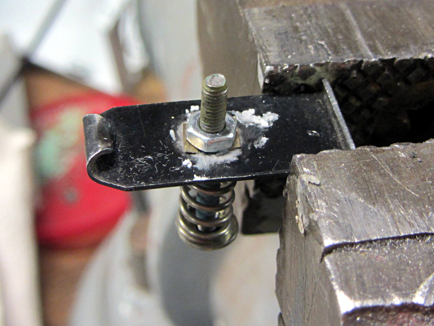
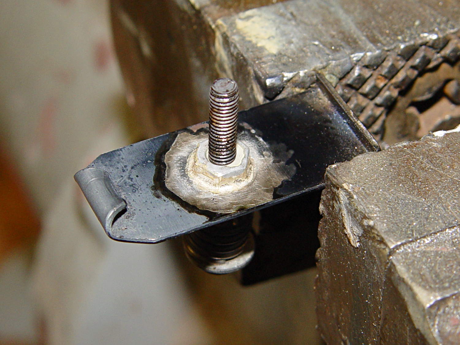
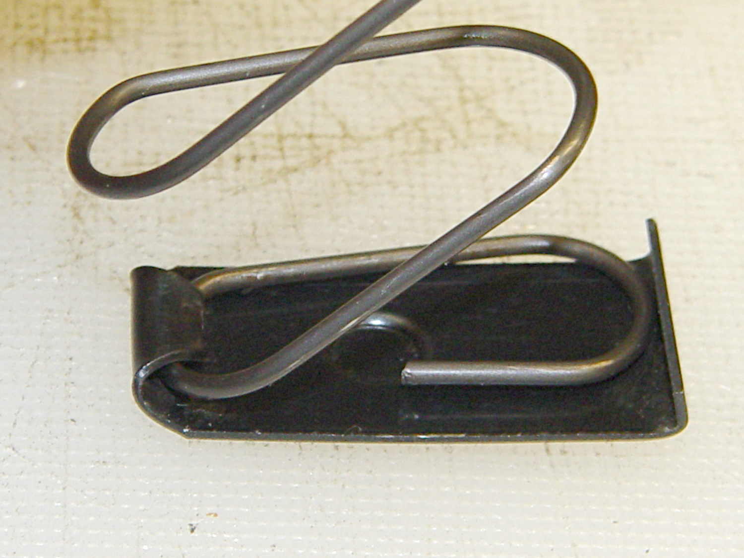
Mount a nut on a spring-loaded screw
Apply paste flux under the nut
Align snippets of silver solder under the nut
Fire the propane torch!
The flux is Ultra-Flux, a nasty concoction intended for silver solder, which in this case is Brownell’s Silvaloy 355 in strip form. Despite the name, it’s 56% silver and has much higher strength than soft tin-lead solder. Although I haven’t done any destructive testing, a good joint will be stronger than the base metals.
The setup before soldering the first nut:
Browning floor plate – nut brazing setup
The spring holds the nut in the proper position, lets it settle straight down as the flux liquefies and the solder melts, then holds it flat against the floor plate to ensure a proper bond and a good fillet. I coated the screw with Tix Anti-Flux to ensure it didn’t become one with the nut.
The same joint after heating:
Browning floor plate – nut brazed 1
The garish red apparently comes from the Anti-Flux; the screw never got more than dull red and was cool by the time I shut off the torch and fiddled with the camera.
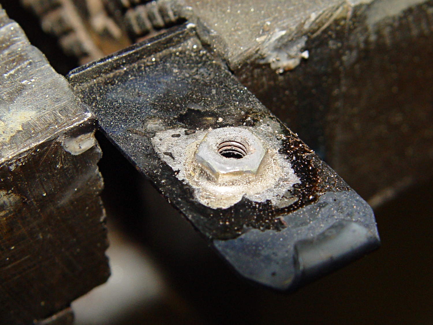
However, the rear of that first nut didn’t get a suitable fillet, so I reheated and removed it to reveal a section where the flux didn’t clean the steel and the solder didn’t flow:
Browning floor plate – nut 1 test
Note that the area below the middle of the nut can’t have a full solder joint, because the nut sits over the depression that forms the boss, thusly:
Browning Hi-Power magazine – drilled floor plate
The solder fillet will, however, surround the nut and bond the ring near the flat part of the plate.
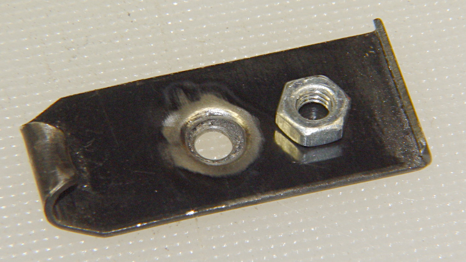
Properly cleaning and brushing that area produced a better joint under a new nut:
Browning floor plate – nut brazed 1a
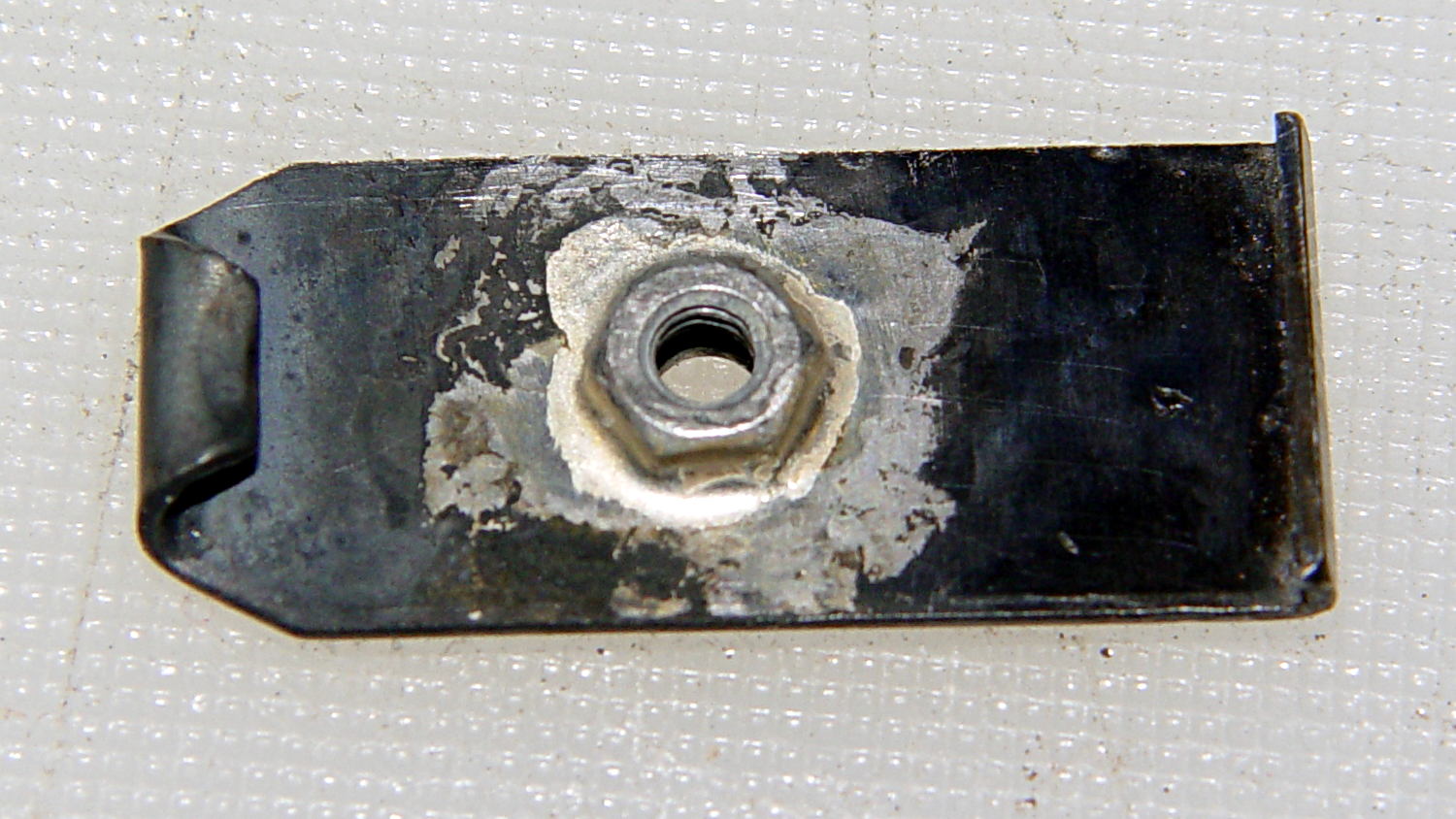
The fillet now extends all the way around the nut, as it should:
Browning floor plate – nut brazed 1a no screw
The crusty appearance comes from the flux residue, which comes off easily in a bath of boiling water to reveal a smooth fillet:
Browning floor plate – defluxed
With cleanliness & good conduct in mind, the remainder of the floor plates brazed smoothly, with good results on the first heating:
Browning floor plate – nut brazed 2
Repeated heating took the starch right out of that poor spring, though…
With brazed plate in hand, the next step will be fitting suitable blocks to the individual floor plates.
(*) My state senator and assemblyperson (or, more exactly, their staffers) have been totally unhelpful in resolving the definition of “readily” as used in the legislation, to the extent that they don’t respond to emails asking about the result of meetings they said they attended with, e.g., State Police counsels, to get more information.
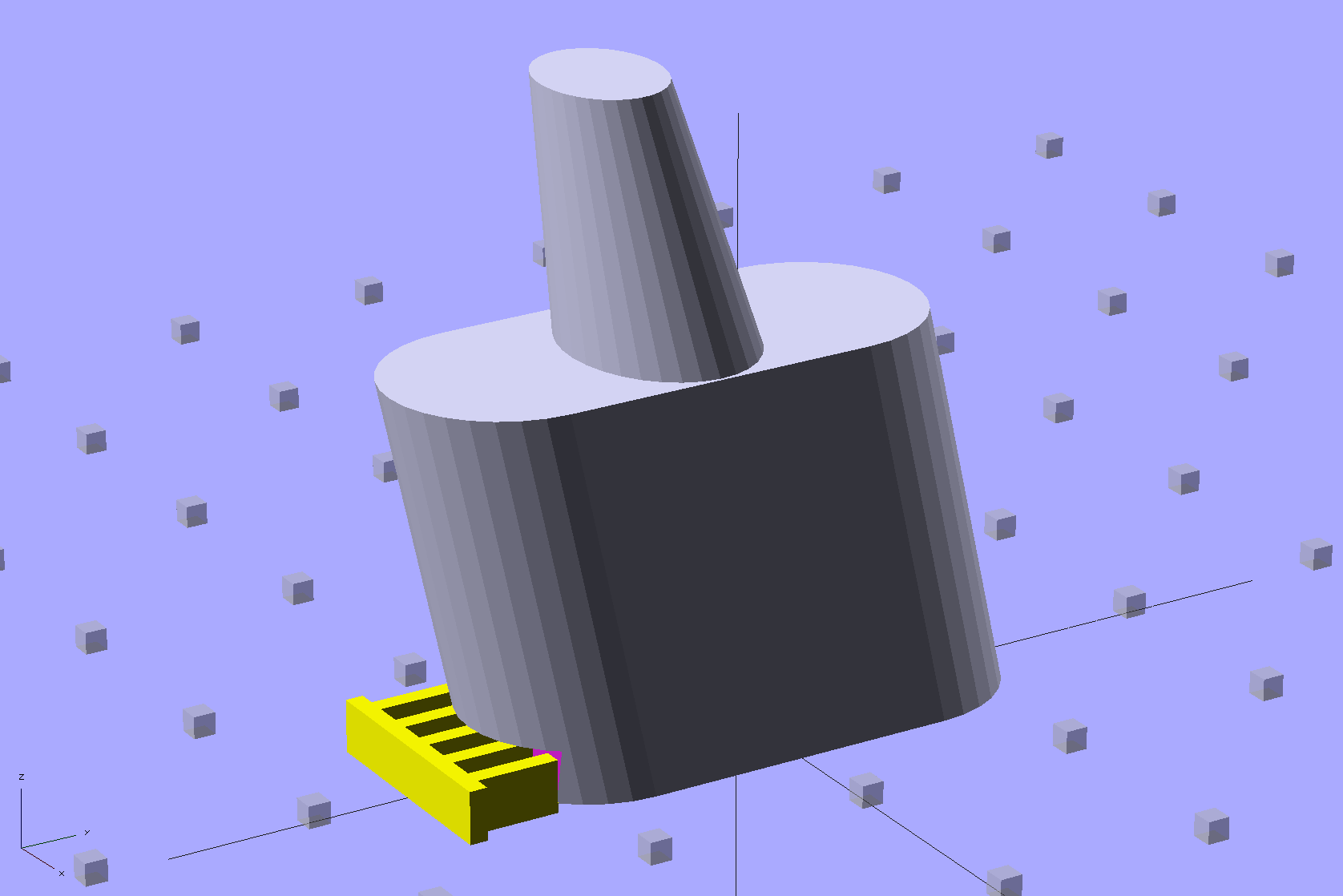
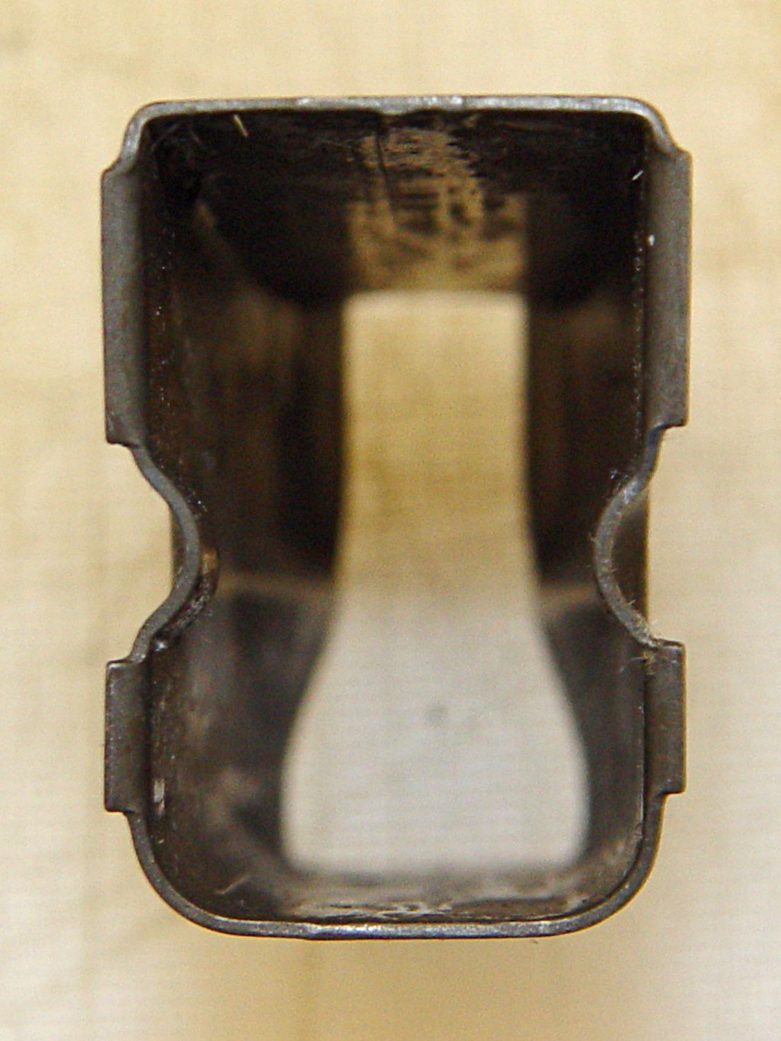
Browning Hi-Power Magazine Block – solid model – whole
The horn fits between the follower’s pegs, so that chopping the pegs off won’t increase the magazine’s capacity. Chopping the horn off without modifying the follower won’t make any difference, either. As nearly as I can tell, chopping the pegs off the follower will destabilize it enough that it’ll roll over atop the spring, but I admit to not actually trying that.
The yellow comb supports the overhang that captures the tab around the magazine spring and there’s a tiny support spider inside the lower nut clearance that holds the ceiling in place:
Browning Hi-Power Magazine Block – solid model – section
The inner nut trap probably droops a bit without any support, but there’s no way to tell when it’s printed as one solid piece. That trap will hold the blob of steel-filled epoxy that secures the screw and helps prevent the block from turning, so it’s not really a nut trap and doesn’t require a precision fit. The vent tube from the top of the screw shaft gives the air and any excess epoxy an exit path.
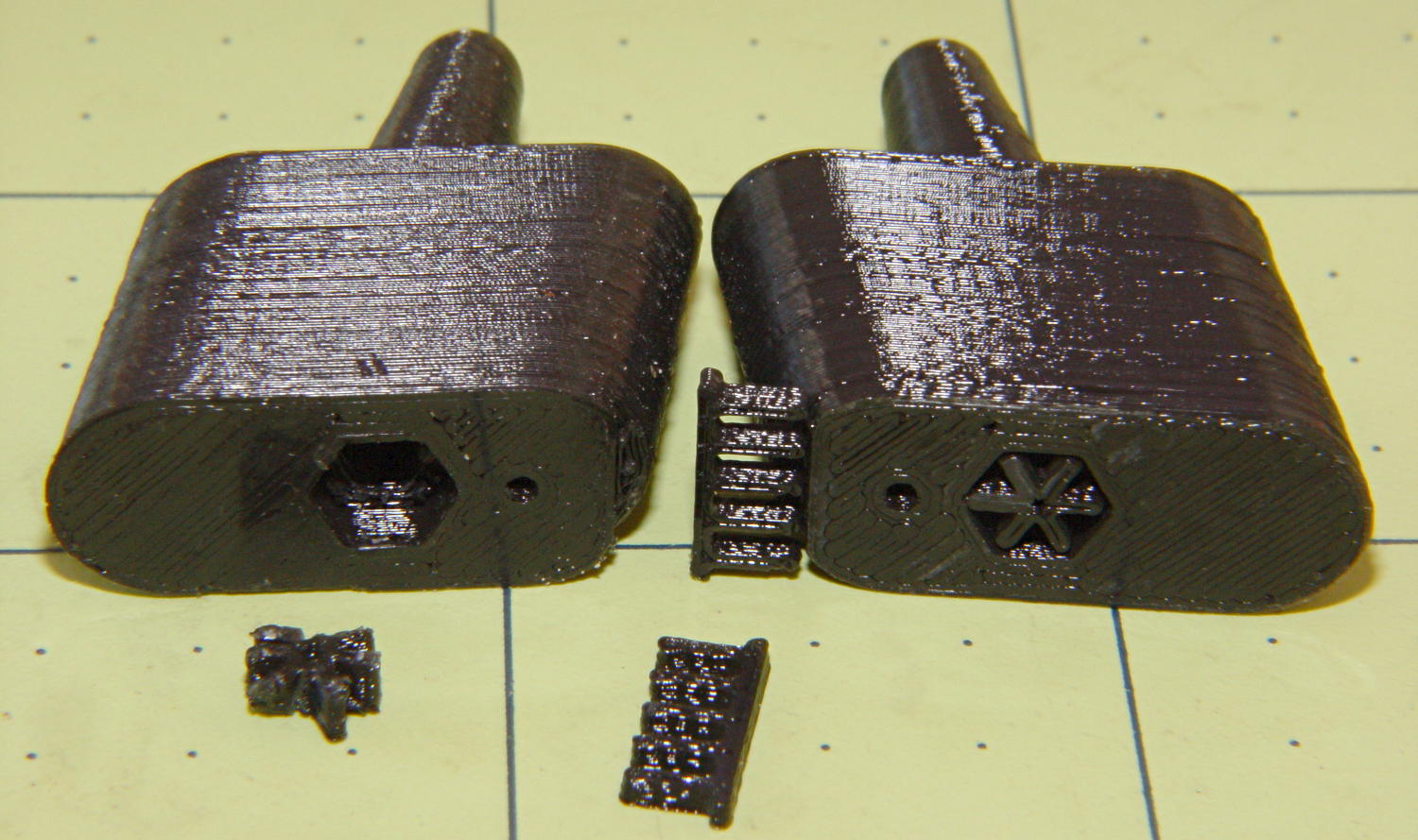
Here’s a bottom view of two blocks, showing the support structures and the results:
Browning Hi-Power magazine – block support detail
I poked the tips of a snap ring pliers into the spider and twisted it out. The comb snaps off with fingernail pressure.
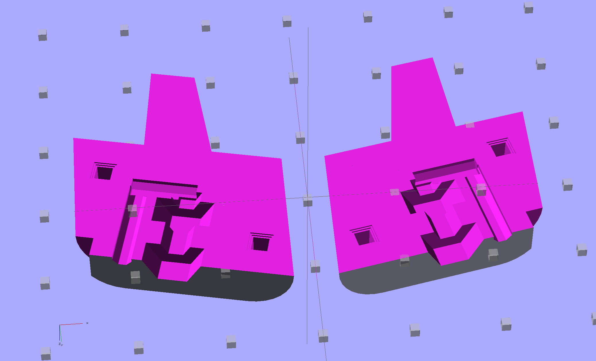
You could also print it without support by laying it flat, then glue the halves together with alignment pins. This is a bottom view:
Browning Hi-Power Magazine Block – solid model – split bottom
The OpenSCAD program has a handful of configuration settings that determine which of those blocks it produces, which components appear, and how it’s oriented.
Installed in a Browning magazine, the block looks like this:
Browning Hi-Power magazine – block in place
A detail of the bottom shows the notch capturing the spring tab:
Browning Hi-Power magazine – block detail
I think the top surface would benefit from a small bevel to ease the spring around the block, but that’s in the nature of fine tuning.
Not having heard back from my legislators yet, I still don’t know whether this counts as a readily reversible modification. I have my doubts, what with it being plastic and all, but we shall see.
The OpenSCAD source code:
// Browning Hi-Power Magazine Block
// Ed Nisley KE4ZNU December 2013

Layout = "Whole";			// Show Whole Split
							//  Show = section view for demo, not for building
							//  Whole = upright for steel or plastic
							//  Split = laid flat for plastic show-n-tell assembly

AlignPins = (Layout == "Split");					// pins only for plastic show-n-tell

Support = (Layout != "Split");						// no support for split

//- Extrusion parameters must match reality!
//  Print with 2 shells and 3 solid layers

ThreadThick = 0.15;
ThreadWidth = 0.40;

HoleWindage = 0.2;

Protrusion = 0.1;			// make holes end cleanly

//----------------------
// Dimensions

Angle = 12.5;				// from vertical

SpringID = 10.3;			// magazine spring curvature (measure with drill shank)
SpringRadius = SpringID / 2;

Length = 24.0;				// front-to-back perpendicular to magazine shaft
Height = 18.0;				// bottom-to-top, parallel to magazine shaft
							//  18 = 10 round capacity

RectLength = Length - SpringID;	// block length between end radii

HornBaseOD = 8.0;			// fits between follower pegs to prevent shortening
HornTipOD = 5.0;
HornAddTip = (HornTipOD/2)*tan(Angle);
HornAddBase = (HornBaseOD/2)*tan(Angle);
HornAddLength = HornAddTip + HornAddBase + 2*Protrusion;
HornLength = 12.0;			// should recompute ODs, but *eh*

TrimHeight = 2.5;			// vertical clearance for spring clip on base plate
							//   OEM = 2.5
							//   generic A = 2.5

TrimInset = 1.5;			// ... horizontal
							//	 OEM = 0.0
							//   generic A = 1.5

ScrewOD = 3.0 - 0.25;		// screw hole dia - minimal thread engagement
ScrewLength = 11.0;
ScrewOffset = -1.5;			//   ... from centerline
							//  OEM = 0.0
							//  generic A = -1.5

NutOD = 5.6;				// hex nut dia across flats
NutThick = 2.4;				//  ... then add 50% to trap for thread engagement & epoxy
NutOffset = 6.0;			//  ... base height from floor

VentDia = 2.0;				// air vent from back of screw recess

PinOD = 1.72;				// alignment pins
PinLength = 6.0;
PinInset = 0.6*SpringRadius;	// from outside edges
echo(str("Alignment pin length: ",PinLength));

NumSides = 8*4;				// default cylinder sides

Offset = 5.0/2;				// from centerline for build layout

//----------------------
// Useful routines

function Delta(a,l) = l*tan(a);				// incremental length due to angle

// Locating pin hole with glue recess
//  Default length is two pin diameters on each side of the split

module LocatingPin(Dia=PinOD,Len=0.0) {

	PinLen = (Len != 0.0) ? Len : (4*Dia);

	translate([0,0,-ThreadThick])
		PolyCyl((Dia + 2*ThreadWidth),2*ThreadThick,4);

	translate([0,0,-2*ThreadThick])
		PolyCyl((Dia + 1*ThreadWidth),4*ThreadThick,4);

	translate([0,0,-(Len/2 + ThreadThick)])
		PolyCyl(Dia,(Len + 2*ThreadThick),4);

}

module PolyCyl(Dia,Height,ForceSides=0) {			// based on nophead's polyholes

  Sides = (ForceSides != 0) ? ForceSides : (ceil(Dia) + 2);

  FixDia = Dia / cos(180/Sides);

  cylinder(r=(FixDia + HoleWindage)/2,
           h=Height,
	   $fn=Sides);
}

module ShowPegGrid(Space = 10.0,Size = 1.0) {

  Range = floor(50 / Space);

	for (x=[-Range:Range])
	  for (y=[-Range:Range])
		translate([x*Space,y*Space,Size/2])
		  %cube(Size,center=true);

}

//----------------------
// The magazine block

module Block(SectionSelect = 0) {

CropHeight = Height*cos(Angle);				// block height perpendicular to base
echo(str("Perpendicular height: ",CropHeight));

	difference() {
		union() {
			intersection() {
				rotate([Angle,0,0])
					hull() {
						for (i=[-1,1])
							translate([0,i*RectLength/2,-((Length/2)*sin(Angle) + Protrusion)])						cylinder(r=SpringRadius,
										h=(Height + 2*(Length/2)*sin(Angle) + 2*Protrusion),
										$fn=NumSides);
					}
				translate([0,0,CropHeight/2])
					cube([2*SpringID,3*Length,CropHeight],center=true);
			}
			translate([0,-Height*sin(Angle),Height*cos(Angle)])
				resize([SpringID,0,0])
					intersection() {
						rotate([Angle,0,0])
							translate([0,0,-(HornAddBase + Protrusion)])
								cylinder(r1=HornBaseOD/2,
										r2=HornTipOD/2,
										h=(HornLength + HornAddLength + Protrusion),
										$fn=NumSides);
					cube([2*SpringID,Length,2*(HornLength*cos(Angle) + Protrusion)],center=true);
				}
		}

		translate([0,ScrewOffset,-Protrusion])		// screw
			rotate(180/6)
				PolyCyl(ScrewOD,(ScrewLength + Protrusion),6);

		translate([0,ScrewOffset,NutOffset])		// nut trap in center
			rotate(180/6)
				PolyCyl(NutOD,1.5*NutThick,6);

		translate([0,ScrewOffset,-Protrusion])		// nut clearance at base
			rotate(180/6)
				PolyCyl(NutOD,(1.1*NutThick + Protrusion),6);

		translate([SpringID/2,-((Length/2)/cos(Angle) - TrimInset),-Protrusion])
			rotate(180)
				cube([SpringID,2*TrimInset,(TrimHeight + Protrusion)],center=false);

		if (AlignPins)								// alignment pins
			for (i=[-1,1])
				rotate([Angle,0,0])
				translate([0,
							(i*((Length/2)*cos(Angle) - PinInset)),
							(CropHeight/2 - i*2*PinInset)])
					rotate([0,90,0]) rotate(45 - Angle)
						LocatingPin(PinOD,PinLength);

		translate([0,(ScrewOffset - NutOD),-Protrusion])	// air vent
			rotate(180/8)
				PolyCyl(VentDia,(ScrewLength + Protrusion),8);
		translate([0,(ScrewOffset + VentDia/2),ScrewLength])
			rotate([90,0,0]) rotate(180/8)
				PolyCyl(VentDia,(NutOD + VentDia),8);

		if (SectionSelect == 1)
			translate([0*SpringID,-2*Length,-Protrusion])
				cube([2*SpringID,4*Length,(Height + HornLength + 2*Protrusion)],center=false);
		else if (SectionSelect == -1)
			translate([-2*SpringID,-2*Length,-Protrusion])
				cube([2*SpringID,4*Length,(Height + HornLength + 2*Protrusion)],center=false);

	}

	NumBars = floor((SpringID/2)/(5*ThreadWidth));

	if (Support) {									// add support structures
		for (i = [-NumBars:NumBars])
			translate([i*5*ThreadWidth,
					   -((Length/2)/cos(Angle) + TrimInset/2 + ThreadWidth),
					   (TrimHeight - ThreadThick)/2])
				color("Yellow")
				cube([(2*ThreadWidth),(3*TrimInset),(TrimHeight - ThreadThick)],center=true);

		translate([-SpringID/2,-((Length/2)/cos(Angle) + 2*TrimInset + ThreadWidth),0])
			color("Yellow")
			cube([SpringID,(2*ThreadWidth),(TrimHeight - ThreadThick)],center=false);

		translate([0,ScrewOffset,0])
			for (j=[0:5]) {
			rotate(30 + 360*j/6)
				translate([(NutOD/2 - ThreadWidth)/2,0,(1.1*NutThick - ThreadThick)/2])
					color("Yellow")
					cube([(NutOD/2 - ThreadWidth),
						  (2*ThreadWidth),
						  (1.1*NutThick - ThreadThick)],
						  center=true);
        }
	}

}

//-------------------
// Build it...

ShowPegGrid();

if (Layout == "Show")
	Block(1);

if (Layout == "Whole")
	Block(0);

if (Layout ==  "Split") {
	translate([(Offset + Length/2),Height/2,0])
		rotate(90) rotate([0,-90,-Angle])
			Block(-1);
	translate([-(Offset + Length/2),Height/2,0])
		rotate(-90) rotate([0,90,Angle])
			Block(1);
}
The general idea is to reduce the capacity of a 13 round Browning Hi-Power magazine to 10 rounds, in compliance with the NY Safe Act, using a number of possibly invalid assumptions. The new Firearms tag will produce earlier posts.
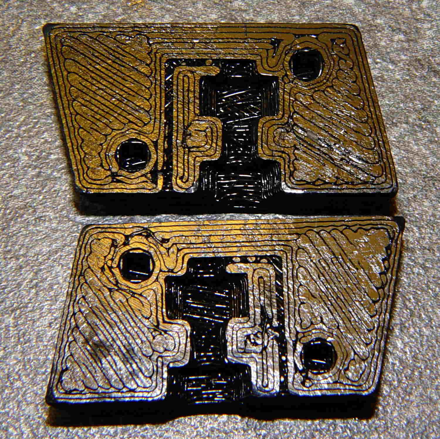
This early prototype tried out the sizes, shapes, and angles, using an M3x0.5 socket head cap screw:
The bottom nut trap locates the block on the inner floor plate by capturing the nut. It might need a bit more clearance or a chamfer to allow for brazing material around the nut flats; cleaning up the brazed nut with a file might also help.
The central trap holds a nut that anchors the block; the trap must be about 50% longer than the nut to allow for thread alignment, because the central hole is a loose tap fit.
That central nut probably isn’t needed, because you’d fill the central shaft with metal-loaded epoxy, which would form a perfectly serviceable, exactly form-fitting, and utterly non-removable “nut”. The vent from the end of the screw shaft releases air trapped behind the epoxy by the screw; if you don’t have a vent, then air pressure will force the epoxy out of the cavity.
If the epoxy “nut” is workable, then you can build it in a single piece printed vertically on the platform. Having a split version makes it easier to show off and, in truth, the cemented joint is about as strong as the rest of the object.
Hot off the M2 3D printer, it looks like this:
BHP magazine block – prototype nut trap – bare
A few threads droop into the air vent, so that channel should be larger. The overall plastic block may be porous enough to release the air pressure even without a vent.
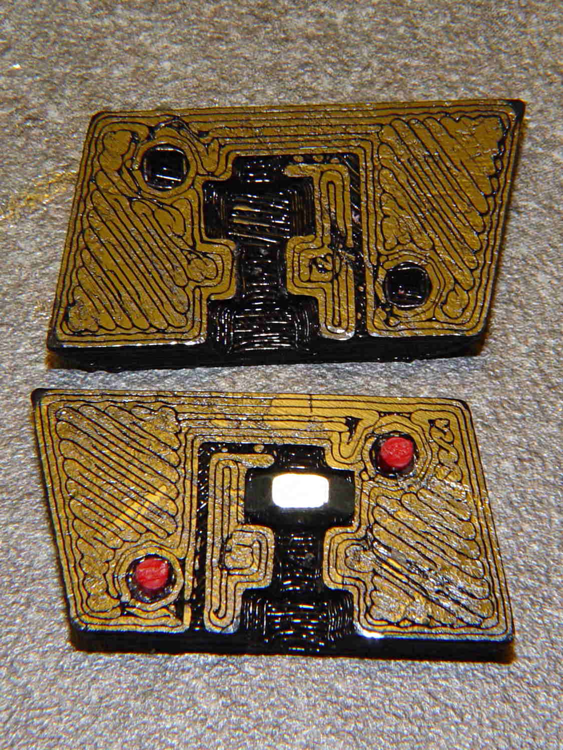
With locating pins glued in place and a nut in the central trap:
BHP magazine block – prototype nut trap
Pretty much as I expected, it doesn’t quite fit in the magazine, because it doesn’t have clearance for the little tab on the inner floor plate that captures the spring.
One might argue that a plastic block isn’t “permanent”, but it’s definitely not “readily” removed:
PLA doesn’t dissolve in common solvents
It doesn’t actually melt and flow away at high temperatures
It’s protected by the spring and inner floor plate
It’s certainly strong enough to resist simple mechanical attacks
This is a start…
The OpenSCAD source code, replete with inadequacies:
// Browning Hi-Power Magazine Plug
// Ed Nisley KE4ZNU November 2013

Layout = "Show";			// Show Whole Pin Build

CrossSection = 1;			// -1, 0, 1 to select section side or none

Section = (Layout == "Build") ? 1 : CrossSection;		// for cross-section for build

//- Extrusion parameters must match reality!
//  Print with 2 shells and 3 solid layers

ThreadThick = 0.25;
ThreadWidth = 0.40;

HoleWindage = 0.2;

Protrusion = 0.1;			// make holes end cleanly

//----------------------
// Dimensions

Angle = 12.5;				// from vertical

EndDia = 10.3;				// an 11/32 inch drill fits
EndRadius = EndDia / 2;

Length = 24.0;				// front-to-back perpendicular to magazine shaft
Height = 14.0;				// bottom-to-top, parallel to magazine shaft
							//  14 = 10 round capacity
							//  28 = 7 round

RectLength = Length - EndDia;	// block length between end radii

ScrewOD = 3.0 - 0.5;		// bottom screw tapping diameter
ScrewLength = 11.0;
ScrewOffset = 0;			//   ... from centerline

NutOD = 5.5;				// hex nut dia across flats
NutThick = 2.4;				//  ... then add 50% for thread engagement & epoxy
NutOffset = 6.0;			//  ... base height from floor

VentWidth = 2*ThreadWidth;	// air vent from back of screw recess
VentDepth = 4*ThreadThick;

NumSides = 8*4;				// default cylinder sides

PinOD = 1.72;				// alignment pins
PinLength = 6.0;
PinInset = 0.9*EndRadius;	// from outside edges
echo(str("Alignment pin length: ",PinLength));

Offset = 5.0/2;				// from centerline for build layout

//----------------------
// Useful routines

// Locating pin hole with glue recess
//  Default length is two pin diameters on each side of the split

module LocatingPin(Dia=PinOD,Len=0.0) {

	PinLen = (Len != 0.0) ? Len : (4*Dia);

	translate([0,0,-ThreadThick])
		PolyCyl((Dia + 2*ThreadWidth),2*ThreadThick,4);

	translate([0,0,-2*ThreadThick])
		PolyCyl((Dia + 1*ThreadWidth),4*ThreadThick,4);

	translate([0,0,-(Len/2 + ThreadThick)])
		PolyCyl(Dia,(Len + 2*ThreadThick),4);

}

module PolyCyl(Dia,Height,ForceSides=0) {			// based on nophead's polyholes

  Sides = (ForceSides != 0) ? ForceSides : (ceil(Dia) + 2);

  FixDia = Dia / cos(180/Sides);

  cylinder(r=(FixDia + HoleWindage)/2,
           h=Height,
	   $fn=Sides);
}

module ShowPegGrid(Space = 10.0,Size = 1.0) {

  Range = floor(50 / Space);

	for (x=[-Range:Range])
	  for (y=[-Range:Range])
		translate([x*Space,y*Space,Size/2])
		  %cube(Size,center=true);

}

//----------------------
// Components

module Block(SectionSelect = 0) {

Delta = tan(Angle)*(Length/2);				// incremental length due to angle

CropHeight = Height*cos(Angle);				// block height perpendicular to base

echo(str("Perpendicular height: ",CropHeight));

	difference() {
		intersection() {
			rotate([Angle,0,0])
				difference() {
					translate([0,0,-Height/2])
						linear_extrude(height=2*Height,convexity=2) {
							for (i=[-1,1])
								translate([0,(i*RectLength/2),0])
									rotate(180/NumSides)
										circle(r=EndRadius/cos(180/NumSides),
												$fn=NumSides);
							square([EndDia,RectLength],center=true);
						}
					for (i=[-1,1])
						translate([0,
									(i*(Length/2 - PinInset)),
									(CropHeight/2 + i*(CropHeight/2 - PinInset))])
							rotate([0,90,0]) rotate(45-Angle)
								LocatingPin(PinOD,PinLength);
				}
			translate([0,0,CropHeight/2])
				cube([2*EndDia,3*Length,CropHeight],center=true);
		}
		translate([0,ScrewOffset,-Protrusion])		// screw
			rotate(180/6)
				PolyCyl(ScrewOD,(ScrewLength + Protrusion),6);

		translate([0,ScrewOffset,NutOffset])		// nut trap in center
			rotate(180/6)
				PolyCyl(NutOD,1.5*NutThick,6);

		translate([0,ScrewOffset,-Protrusion])		// nut clearance at base
			rotate(180/6)
				PolyCyl(NutOD,(1.1*NutThick + Protrusion),6);

		translate([0,-(ScrewOffset + NutOD),(ScrewLength - Protrusion)/2])	// air vent
			cube([VentDepth/2,VentWidth,(ScrewLength + Protrusion)],center=true);
		translate([0,(ScrewOffset - NutOD/2),(ScrewLength - VentWidth/2)])
			cube([VentDepth/2,NutOD,VentWidth],center=true);

		if (SectionSelect == 1)
			translate([EndDia,0,Height/2-Protrusion])
				cube([2*EndDia,3*Length,Height+2*Protrusion],center=true);
		else if (SectionSelect == -1)
			translate([-EndDia,0,Height/2-Protrusion])
				cube([2*EndDia,3*Length,Height+2*Protrusion],center=true);
	}

}

//-------------------
// Build it...

ShowPegGrid();

if (Layout == "Pin")
	LocatingPin(PinOD,PinLength);

if (Layout == "Show")
	Block(CrossSection);

if (Layout == "Whole")
	Block(0);

if (Layout ==  "Build") {
	translate([(Offset + Length/2),Height/2,0])
		rotate(90) rotate([0,-90,-Angle])
			Block(-1);
	translate([-(Offset + Length/2),Height/2,0])
		rotate(-90) rotate([0,90,Angle])
			Block(1);
}
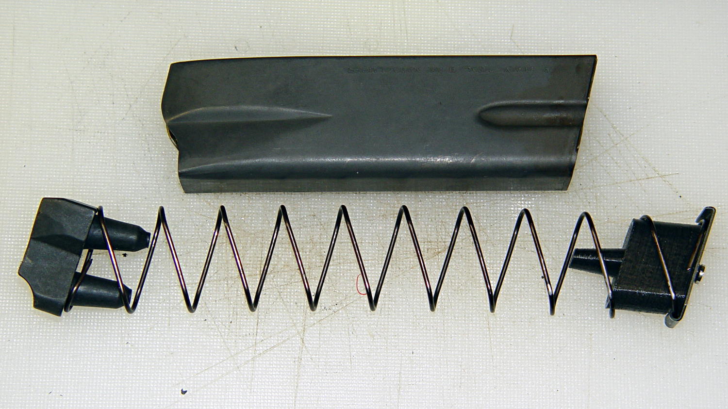
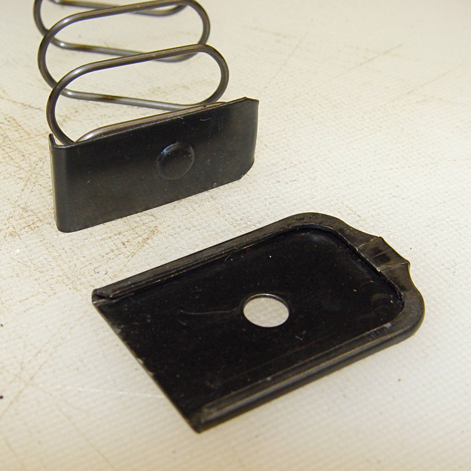
The Browning Hi-Power magazine has two floor plates:
the interior plate captures the spring and locates it properly inside the magazine case
the exterior plate provides reaction force against the spring and locates the interior plate’s boss
Browning Hi-Power magazine – base plates
The interior plate has two critical features:
the ramp on the front (to the right) that guides it over the edge of the exterior plate
the boss that latches the exterior plate in place
If you remove the interior plate, you must somehow hold the spring in place while sliding the exterior plate in place, after which the spring is free to thrash around inside the magazine under recoil forces.
An important point: you can buy exterior floor plates from all the usual sources, but, as nearly as I can tell, nobody sells replacement interior floor plates and they’re not included in kits of replacement springs. If you don’t have an interior floor plate, you must fabricate one from scratch before you can use the magazine.
So one thought is to drill a hole in the middle of the boss:
Browning Hi-Power magazine – drilled floor plate
OK, that’s not quite centered, but it’ll suffice.
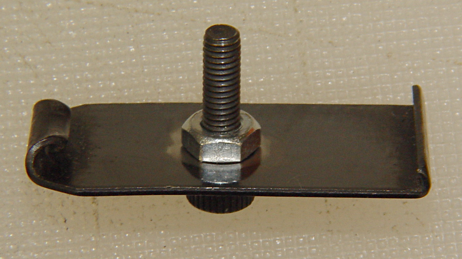
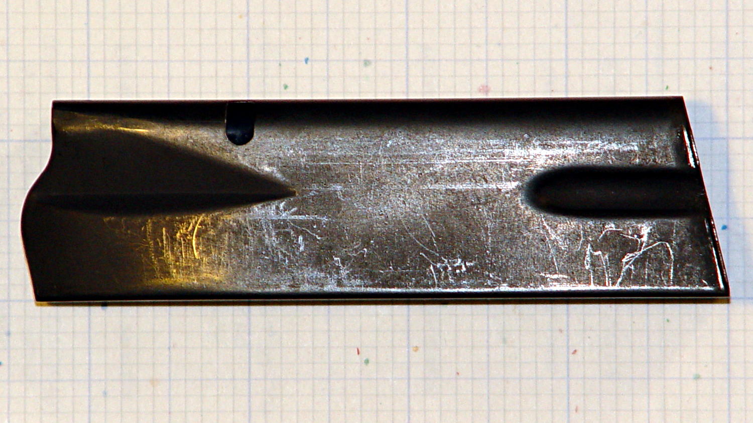
Wire-brush the coating around the inside of the boss to prepare it for brazing, then braze a nut onto the inside of the floor plate (which I haven’t done yet), and run a socket-head setscrew through it:
Browning Hi-Power magazine – drilled floor plate
If that threaded into a block loaded with steel-filled epoxy, it’d never come back out again. You could machine the head down to a flat disk that would fit through the existing hole in the exterior floor plate and not provide any gripping surface:
BHP floor plate screw – disk head
To be absolutely certain, you could file the entire socket head off flush with the boss, leaving no way to grip the screw.
If the block surrounds the nut on the floor plate with a generous helping of steel-filled epoxy, then there’s no way to twist the block off the plate.
If the block also captures the spring, then you can’t heat the plate enough to un-braze the nut without also de-tempering and wrecking the spring.
I can think of a few other ways to attack it, but none seem like a project that would readily convert the magazine into one holding a few more rounds. Opinions may differ, of course, but …
The Browning Hi-Power magazine case has a 12.5° forward angle with respect to the floor plates:
Browning Hi-Power magazine – components
The natural axes lie parallel and perpendicular to the case axis, which means dimensions parallel and perpendicular to the floor plates (horizontal & vertical, respectively) require a bit of trigonometry. This doodle sketches some of the key values, not all of which are hereby asserted to be correct:
Magazine angle doodles
Name the variables:
Slant angle α
Height H along magazine axis
Length L perpendicular to H
Components of H:
vertical = H cos α
horizontal = H sin α
Components of L:
vertical = L sin α
horizontal = L cos α
Extreme point of the tilt at the edge, relative to center point on axis:
vertical = (L/2) sin α
horizontal= (L/2) cos α
Projection of top parallel to axis onto horizontal:
L / cos α
I suppose one could set up functions for all that, but I tend to just hammer out the trig where it’s needed.
The follower has 15.3 mm long pegs that taper from 8.75 mm to 7 mm, on 14.5 mm centers. The spring compresses down to a little longer than that with 13 rounds atop the follower:
Browning Hi-Power magazine – follower
The top of the follower has a rather complex shape (yes, that’s a crunch toward the front of the ridge):
Browning Hi-Power magazine – follower top
The front view shows more curves:
Browning Hi-Power magazine – follower front
Judging from the online pictures, BHP followers have taken on a wide variety of shapes over the decades, so I’d expect almost anything would work more-or-less well.
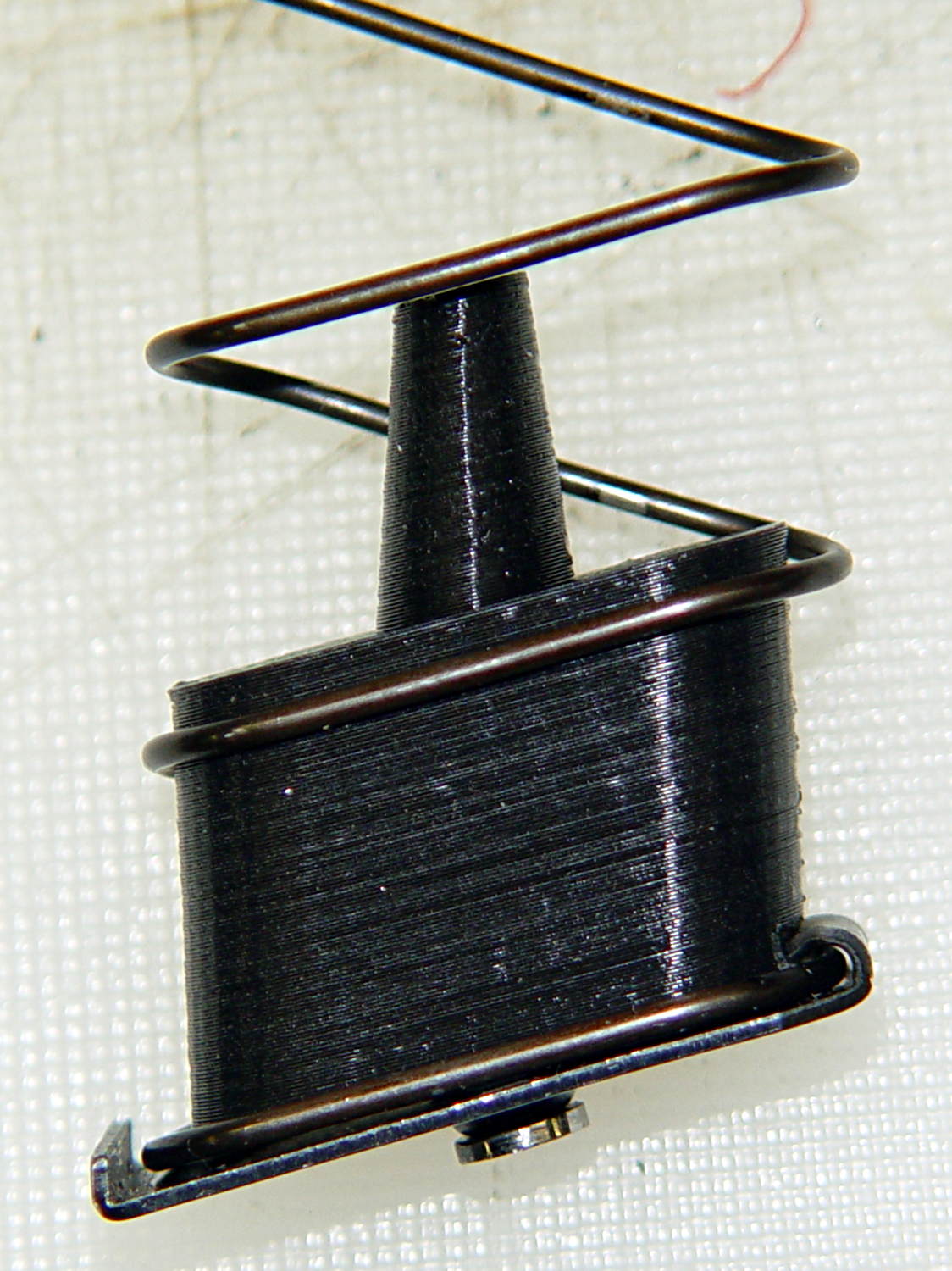
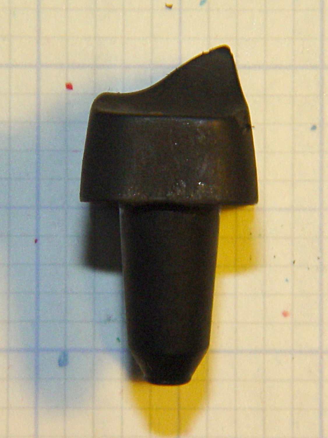
The inner floor plate attaches to the spring and has a 5 mm dia x 1 mm tall boss that matches the hole in the outer floor plate:
Browning Hi-Power magazine – base plates
The hole in the outer floor plate is a scant 5.4 mm, just slightly under the head size of a 3.0×0.5 mm socket head cap screw. The OEM Browning magazines have a centered boss, but some aftermarket magazines move it a millimeter or so to the front or rear. The outer plate seems hard enough to be just about spring steel.
A tab on the front of the inner floor plate (to the left in this picture captures the spring:
Browning Hi-Power magazine – spring inside base plate
The inner plate is 0.75 mm mild steel and may be removable, depending on how tightly the tab got crunched during manufacturing. The tab extends a millimeter or so beyond the spring on the inside of the curve and is about 2 mm tall at that point.
The boss on the inner plate and the hole on the outer plate locate the spring at the proper position and also ensure the outer plate doesn’t accidentally slide off; you must push the boss inward to release the outer plate before sliding it forward. Using a rounded rod lets you push the inner plate far enough inward to release the spring pressure on the outer plate, making it much easier to slide; in fact, for my fingers, I can’t move the outer plate without inserting a rod in the hole.
The case is a seamless 0.7 mm thick high-carbon-steel tube with complex curves:
Browning Hi-Power magazine – case on grid paper
The “high carbon” part means that it’s not in the least bendy; a few operations on large presses mashed it into that shape and it’s not going to take on anything else by accident. The feed lips on the top can get bent if you abuse the thing, but that’s about it.
The case is 20.5 x 31.7 mm from the base to the latch hole, 99 mm long in front and 109 mm long in the back. The latch hole is 4.2 x 7.3 mm with a 2.7 mm notch in the front side, 67.2 mm from the base and 27.7 mm from the top. The angle of the case axis with respect to the bottom (on the right) is 12.5°.
Inside measurements at the base: 30.5 x 18.7 mm. The rear corners are essentially right angles and the front curves fit 1/4 inch = 6.3 mm or 9/32 inch = 7.1 mm drills.
The lower flutes are 26 x 6.5 mm, centered on the side (even though it doesn’t look that way), and compress the outside of the case to 16.2 mm and the inside to 14.7 mm. The tabs engaging the outer floor plate are 23 mm edge-to-edge, 10.5 mm and 6.0 mm long, and protrude 1.5 mm from the outside of the case:
Browning Hi-Power magazine – bottom
The top of the case is 10.5 mm wide at the rear of the feed lips, with the sharp bend 17.0 mm from the outside of the rear face:
Browning Hi-Power magazine – top
The spring is 1.25 mm = 49 mil wire, 143 mm flat-to-flat high, about 15.1 mm turn-to-turn, 13/32 inch = 10.3 mm ID at the ends, 13.2 mm outside width, 25 mm inside length, and 27 mm outside length. Those don’t quite add up, but the whole thing is, well, springy.
The spring exerts these crudely measured forces:
1 round = 1.1 kg
10 rounds = 2.5 kg
The follower moves 5.3 mm, so the spring constant is very roughly 0.26 kg/mm = 14.8 pound/inch. Aftermarket springs tout their stiffness and come in 5% increments of additional force, so that’s probably not a critical number.
Limiting the capacity of a magazine so that it cannot be “readily” converted back to a higher capacity seems difficult, particularly if you allow disassembling the magazine for proper cleaning and maintenance. If operator safety and proper function isn’t a concern, then many things become possible.
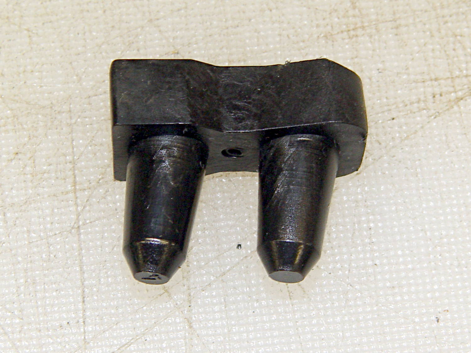
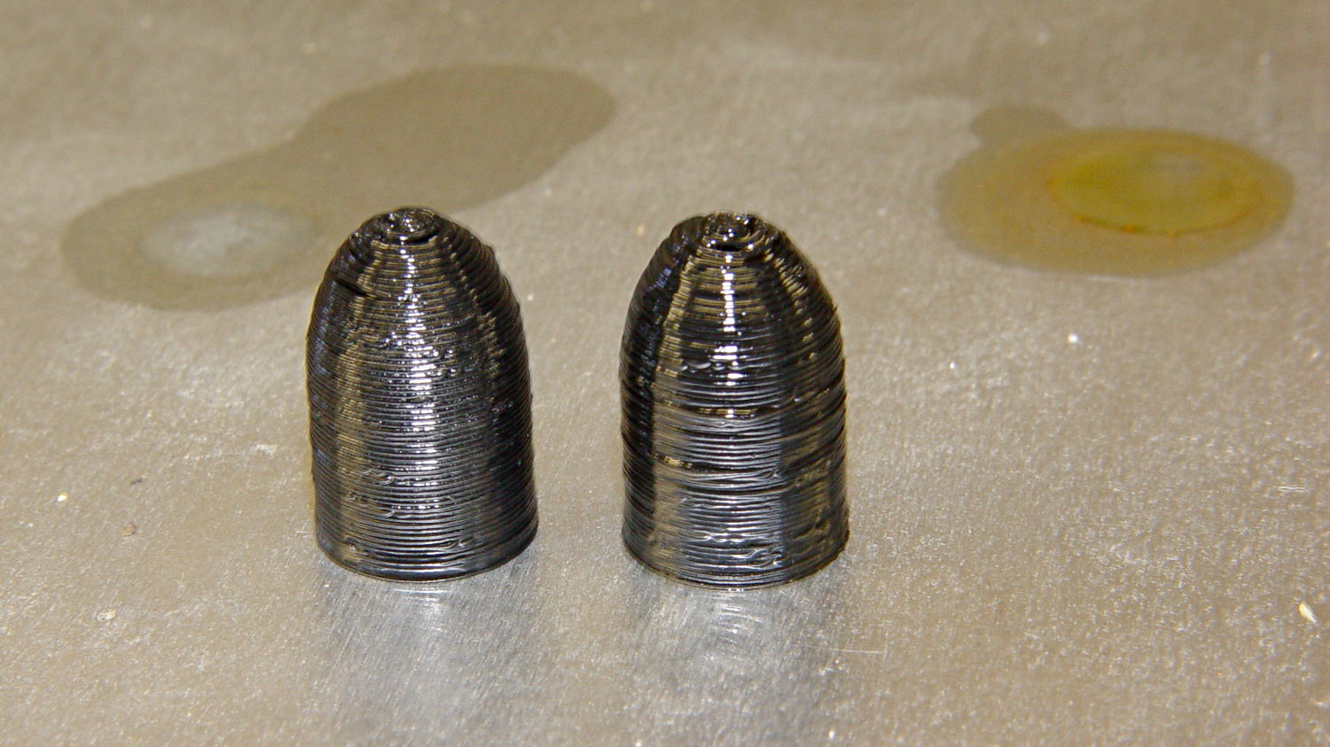
According to Wikipedia, Polylactic acid, a.k.a. PLA “is soluble in chlorinated solvents, hot benzene, tetrahydrofuran, and dioxane” and is not soluble in acetone, alcohol, or water.
Just to see what happens, I dunked a pair of those 3D printed dummy bullets in Shooter’s Choice Gun Solvent (which has since gone obsolete) and Hoppe’s No. 9 Gun Bore Cleaner (which seems to have been reformulated several times), then let them air-dry in those background puddles:
PLA dummy bullets after solvent bath
Nothing much happened: they’re not soft or gummy, haven’t slumped, and seem undaunted.
That’s in contrast to ABS plastic, which isreadily soluble in acetone and the aromatic hydrocarbons commonly found in solvents used around firearms. Apart from that, ABS would be a slightly better choice on mechanical grounds. I’m not sure the difference really matters for most purposes, given the very wide tolerances on 3D printed objects.