The Smell of Molten Projects in the Morning

Ed Nisley's Blog: Shop notes, electronics, firmware, machinery, 3D printing, laser cuttery, and curiosities. Contents: 100% human thinking, 0% AI slop.

Tag: CNC

Making parts with mathematics

  • Another Circumferential Seat-Frame Clamp

    This is another step along the way to getting our daughter’s radio firmly mounted to her Tour Easy, not tucked into one of the panniers. The general idea is to use a water bottle holder for the radio, with a seat wedge pack from an upright bike cushioning the radio. The secret ingredient is a circumferential clamp that mounts the holder to the lower rail of the bike’s seat frame.

    This clamp is basically the same as the ones on our bikes, but I doodled up a sketch with some illegible dimensions that almost matches the actual clamp; we may both find it useful the next time.

    Clamp layout sketch
    Clamp layout sketch

    Machining the clamp is straightforward: bandsaw a block of about the right size, square it up in the mill, helix-mill the clamp hole …
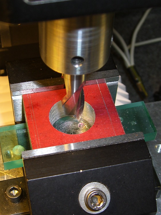
    Helix-milling the clamp hole
    Helix-milling the clamp hole

    Drill the clearance and tapping holes for the screw, bandsaw it in half, clean up the cut edges …
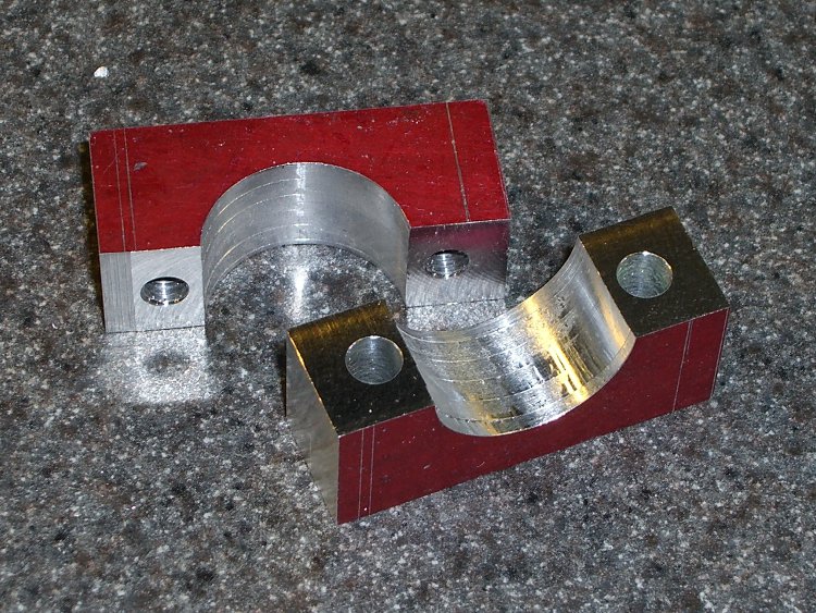
    Finished clamp parts
    Finished clamp parts

    Obviously, I didn’t put those nice bevels on the front side.

    Both previous water bottle holders required a spreader plate between the clamp screws and the holder’s screws, but this time the holder had a nice aluminum plate all by itself. It just fit on the Sherline and a bit of manual CNC center-drilled the curved plate and poked a jobber-length drill through the holes …

    Drilling holder for clamp screws
    Drilling holder for clamp screws

    And then it fit perfectly on the bike …

    Mounted holder
    Mounted holder

    A side view …

    Mounted holder - side view
    Mounted holder – side view

    Now, to find a wedge pack big enough for the HT and small enough to fit in the holder!

  • Casting Machinable Wax: Oops!

    Remelted machinable wax
    Remelted machinable wax

    I put a new bag in the vacuum cleaner while machining the prototype case for the bike radio adapters, which was a Good Thing: the swarf from those two halves filled the entire bag!

    I gutted the bag and dumped the swarf in a pot to melt down for another use. It started as a brick, but I figured having some rounds might come in handy. A bit of rummaging turned up some pill bottles of just about the right size.

    Unfortunately, I didn’t think quite far enough ahead: notice the shoulder around the right-hand end of the shorter cylinder? Yeah, the bottom of the bottle was bigger than the top…

    Fortunately, I don’t have a deep emotional attachment to the bottles, so carving it off the wax wasn’t a traumatic experience. Things would be different if I’d made a nice custom mold…

    Of course, the vacuum cleaner also sucked up the odd screw, paper snippet, older swarf left in nooks and crannies, and some of this and a bit of that. Most of the junk either floats to the top or sinks to the bottom, leaving the rest of the wax in good shape. I suppose I could filter the melt, but it’s pretty thick & gooey, even at 300 °F, and I doubt my cheesecloth is up to the task.

    Memo to Self: Do a better job of cleaning up before machining the wax, OK?

  • Machinable Wax: First Cuts

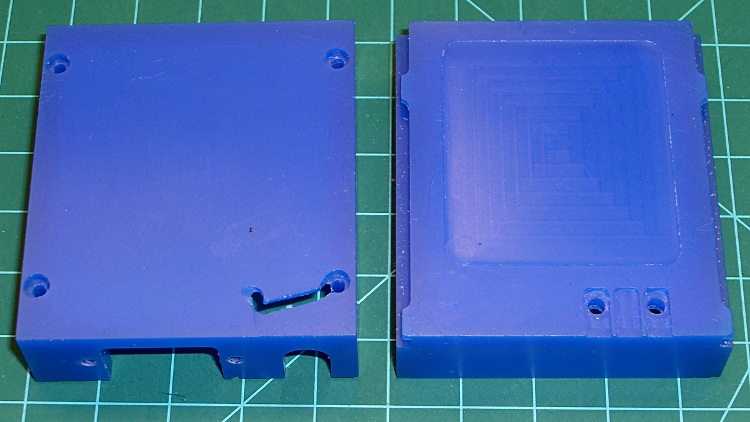
    This is a prototype for the case that will eventually hold a TinyTrak3 GPS-to-APRS encoder, along with a homebrew circuit board that combines the APRS data with voice from the helmet mic. The case slides into the back of our ICOM IC-Z1A and W-32A HTs, replacing the battery case.

    It’s the most complex CNC machining I’ve done so far and I figured that was the perfect reason to carve up a block of machinable wax that’s been sitting on the shelf for far too long.

    The exterior view shows why you use wax for the first pass… the ugly gash came from not retracting the end mill before the final G30, combined with trying to clamp a bendy shell in the vise. That was, of course, the final operation on that part!

    Machinable wax case - exterior
    Machinable wax case – exterior

    The inside view shows the TinyTrak serial connector cutout (left half), as well as the shoulder to support the audio interface circuit board (right half). The two holes at the upper-right are 4-40 clearance for screws that serve as contacts for the HT’s battery connection and hold the board in place.

    Machinable wax case - interior
    Machinable wax case – interior

    These survived far too many setups and takedowns as I figured out how to get all the cuts laid out and in what sequence to do everything. Now that I know a bit more about what to do, the plastic version should come out better; I’m sure I’ll also make better mistakes.

  • Sherline Tool Table

    Having recently converted to EMC 2.4 and switched the tool table to the new format, I took the opportunity to add a few useful drills.

    Low numbers are random end mills & suchlike. Number drills run from 100 to 180, and I’ll add more as I need ’em. Fraction drills run from 201 through 264, although it’s highly unlikely I’ll ever fit a 64/64-inch drill in a chuck that also fits in the Sherline spindle.

    All the Z lengths are exactly 1, because I now have a tool length probe that is absolutely wonderful.

    In practice, I use the tool table mostly to tell Axis how to draw the tool cylinder in the backplot, because I feed in most diameters directly in the G-Code. The Axis “manual toolchanger” routine prompt will now serve as a mnemonic for the actual size, but I write the G-Code to emit a (debug, #Drill_Size) message for clarity.

    The  Sherline.ini file references the tool table with the line:

     TOOL_TABLE = Sherline.tbl

    Herewith, Sherline.tbl:

    ; Common end mills
    T1 P1 Z1 D0.1225    ; 1/8
    T2 P2 Z1 D0.1535    ; 5/32
    T3 P3 Z1 D0.187        ; 3/16
    T4 P4 Z1 D0.25        ; 1/4
    T5 P5 Z1 D0.3122    ; 5/16
    T6 P6 Z1 D0.374        ; 3/8
    T7 P7 Z1 D0.4374    ; 7/16
    T8 P8 Z1 D0.4720    ; 1/2
    T20 P20 Z1 D0.09787 ;  2 mm
    ; Number drills
    T107 P107 Z1 D0.201 ;  7     5.11    10-32 clear
    T109 P109 Z1 D0.196 ;  9     4.98    10-32 clear
    T118 P118 Z1 D0.170 ; 18     4.32     8-32 clear
    T121 P121 Z1 D0.159 ; 21     4.04    10-32 tap
    T127 P127 Z1 D0.144 ; 27     3.66     6-32 clear
    T129 P129 Z1 D0.136 ; 29     3.45     8-32 tap
    T136 P136 Z1 D0.107 ; 36     2.72     6-32 tap
    T132 P132 Z1 D0.116 ; 32     2.95     4-40 clear
    T143 P143 Z1 D0.089 ; 43     2.26     4-40 tap
    T141 P141 Z1 D0.096    ; 41     2.44     2-56 clear
    T148 P148 Z1 D0.076 ; 48     1.93     1-72 clear
    T150 P150 Z1 D0.070    ; 50     1.78     2-56 tap 0-80 clear
    T152 P152 Z1 D0.064 ; 52     1.63     0-80 clear
    T153 P153 Z1 D0.060 ; 53     1.52     1-72 tap
    ; Letter drills
    T203 P203 Z1 D0.047 ;  3/64     1.2     0-80 tap
    

    It turns out that the tool table has an undocumented limit of 50-some-odd entries, at least in EMC2 2.4.1. That puts the kibosh on my plans to add a bunch of entries to cover all the drill sizes Eagle might require for a PCB. More on that in a while …

  • Turning Off Gnome Desktop Tooltips

    This probably isn’t applicable to the Latest and Greatest, but for the Ubuntu 8.04 version used by EMC…

    gconftool -s --type=bool /apps/panel/global/tooltips -enabled false
    
  • Re-rebuilding a Recumbent Antenna Mount

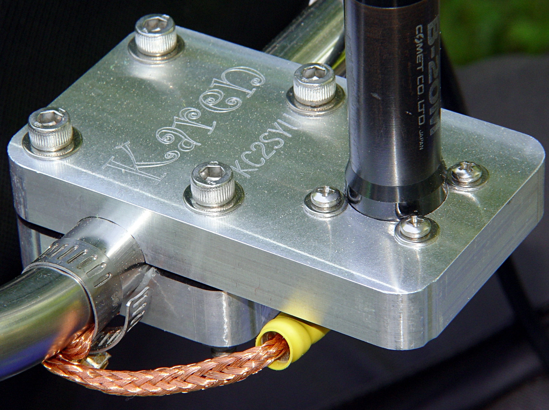
    Antenna Mount
    Antenna Mount

    Quite a while ago, I built this slab mount to hold an amateur radio antenna on our daughter’s Tour Easy. It worked fine until the bike blew over and whacked the antenna whip against something solid, at which point the mast cracked.

    The antenna screws into an ordinary panel-mount UHF connector secured to the bottom of the slab, with a hole through the slab just large enough to accept the antenna mast. That put all the mechanical stress on the slab, not the connector.

    Modified antenna mounting plate
    Modified antenna mounting plate

    Alas, the new antenna had a slightly different mast outside diameter, so I machined a new adapter to clamp the connector atop the slab. The antenna screws down into the adapter against a brass washer, again keeping the strain on the fitting.

    I recently found the commercial mobile antenna cable that I’d been meaning to use on her bike, which required Yet Another Modification to that slab. It turns out that the UHF connector on the cable expects to be secured to sheet metal found in a car body, rather than a half-inch aluminum plate: the threads aren’t long enough!

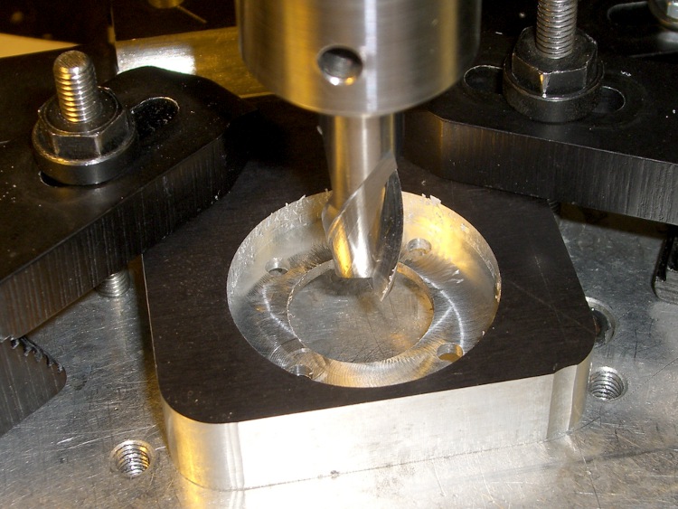
    So I machined circular recesses on the top and bottom to hold the mounting nut and washer, respectively, with 2 mm of aluminum remaining in the middle of the slab.

    Milling top recess
    Milling top recess

    The recesses are just fractionally larger than the nut & washer, so most of the stress gets transmitted directly to the slab. Even in the high-vibration bicycle environment, I think there’s enough meat in there to prevent fatigue fractures.

    Milling bottom recess
    Milling bottom recess

    I recycled a G-Code routine I’d written to chew out circular recesses. It does a bit of gratuitous (for this application, anyway) spiraling in toward the center, but got the job done without my having to think too much.

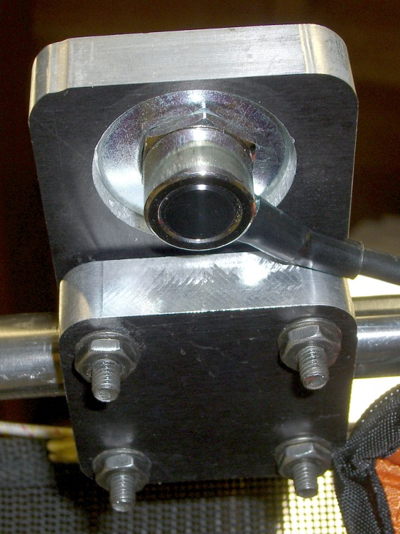
    The bottom view shows the washer in action. The recess is deep enough that the cable just barely clears the slab.

    Modified mounting plate - bottom
    Modified mounting plate – bottom

    The top view shows the recessed mounting nut. The nut has an O-ring around the connector threads, but the water will probably drain out through the four through-holes left over from the old panel-mount connector.

    Modified mounting plate
    Modified mounting plate

    I turned the top nut down as far as I could with a wrench & (ugh) needle-nose pliers, then tightened the bottom nut about 1/3 turns with a wrench.

    You’re not supposed to notice the crispy edges on the PVC bushing holding the reflector to the antenna mast. The high setting on that heat gun is a real toaster…

    The G-Code is over there.

  • Sherline CNC Mill: Defining Home Switches

    Having mounted & wired the switches, the next step involves defining the homing sequence & configuration for each axis. All this goes in Sherline.ini and is adapted from the doc there.

    The travel limits are somewhat empirical and I think the Y axis will require some adjustment due to the tooling plate switch extender gadget.

    The HOME_SEARCH_VEL values may be a bit too high, given the rather lethargic 5.0 in/sec^2 acceleration I’m using for X & Y, with just 3.0 for Z. I’ve heard the occasional thwack as the switch trips, so maybe 20 mils of overtravel isn’t quite enough.

    For the X-Axis:

    [AXIS_0]
    ... snippage ...
    MIN_LIMIT = -1.0
    MAX_LIMIT = 9.5
    HOME_IS_SHARED = 1
    HOME_SEQUENCE = 2
    HOME_SEARCH_VEL = 4.75
    HOME_LATCH_VEL = 0.016
    HOME_FINAL_VEL = 0.25
    HOME_OFFSET = 9.1
    HOME = 4.5
    

    For the Y-axis:

    [AXIS_1]
    ... snippage ...
    MIN_LIMIT = -0.5
    MAX_LIMIT = 4.95
    HOME_IS_SHARED = 1
    HOME_SEQUENCE = 1
    HOME_SEARCH_VEL = -4.75
    HOME_LATCH_VEL = -0.016
    HOME_FINAL_VEL = 0.25
    HOME_OFFSET = 0.0
    HOME = 4.5
    

    For the Z-axis:

    [AXIS_2]
    MIN_LIMIT = -0.1
    MAX_LIMIT = 6.9
    HOME_IS_SHARED = 1
    HOME_SEQUENCE = 0
    HOME_SEARCH_VEL = 0.333
    HOME_LATCH_VEL = 0.016
    HOME_FINAL_VEL = 0.25
    HOME_OFFSET = 6.9
    HOME = 6.5
    

    The A axis doesn’t get a home switch because I can’t imagine needing one for a rotary table:

    [AXIS_3]
    ... snippage ...
    MIN_LIMIT = -9999.0
    MAX_LIMIT = 9999.0
    HOME_SEARCH_VEL = 0
    HOME_LATCH_VEL = 0
    HOME = 0.0