The Smell of Molten Projects in the Morning

Ed Nisley's Blog: Shop notes, electronics, firmware, machinery, 3D printing, laser cuttery, and curiosities. Contents: 100% human thinking, 0% AI slop.

Tag: CNC

Making parts with mathematics

  • Erasing a Hole

    Turning the plug OD
    Turning the plug OD

    The scrap pile disgorged a chunk of aluminum plate exactly the correct size for a heat spreader that will mate eight power FETS to that heatsink. The catch: a 1-1/4-inch deep hole tapped 1/4-20 for about 3/4 inch at almost the right spot along one end. Rather than sawing off Yet Another Chunk from the original plate, I figured it’d be more useful to just plug the hole.

    Note that this is somewhat different than the situation described there, where I screwed up by putting a hole in the wrong place. Here, I’m just being a cheapskate by making a piece of junk good enough to use in a project, rather than having it kick around in the scrap pile for another decade.

    Anyway.

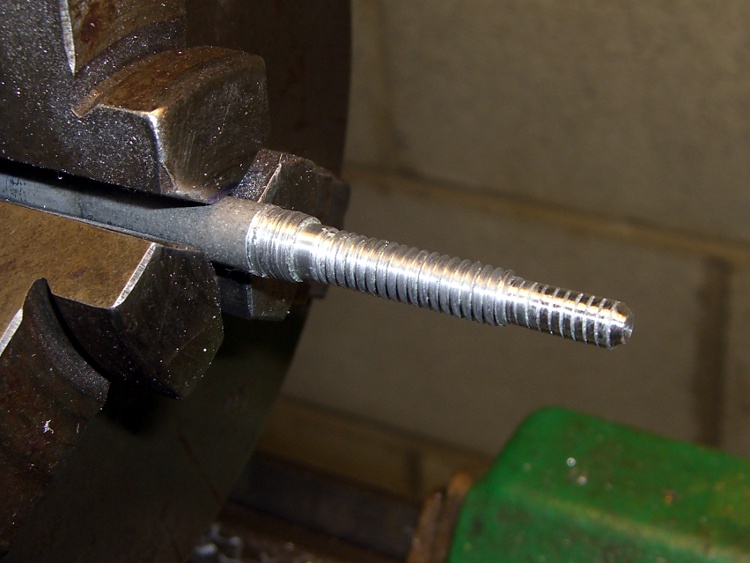
    I turned a 3/8-inch diameter aluminum rod down to 1/4 inch for the threaded part and a bit under 0.200 inch to fit into the partially threaded end.

    A real machinist would single-point the thread, but I just screwed a die over it. The narrow end is slightly larger than the minor thread diameter, which helped get things started. Then a trial fit, saw off the excess on the skinny end, and apply a touch of the file to shape the end to mate with the hole’s drill-point bottom:
    Threaded hole plug
    Threaded hole plug
    Plug epoxied in place
    Plug epoxied in place

    I buttered up the plug with a generous helping of JB Weld epoxy and screwed it in. Toward the end of that process, the air trapped in the end became exceedingly compressed, to the extent I had to stop after each quarter-turn to let it ooze outward; eventually the hole gave off a great pffft as the remaining air pooted out. Unscrewed slightly to suck some epoxy back in, screwed it tight, and let it cure overnight.

    Squared-up block with plugged hole
    Squared-up block with plugged hole

    Sawed off the plug, filed the rubble more-or-less smooth, then squared it in the Sherline mill. The heatsink prefers to sit on a nice, smooth metal surface, so I flycut the other side of the block to get rid of a few dings and the entire anodized layer while I was at it.

    The epoxy ring doesn’t have a uniform width, because you’re looking at a cross section of the thread. The skinny part is the crest of the plug thread, the wide part is along one flank. Barely a Class 1A fit, methinks.

    New hole
    New hole

    Locate the midpoint of the block’s end, center-drill, then poke a new #29 hole 20 mm deep (I really do prefer metric!) for an 8-32 screw. The plug didn’t move at all during this process, pretty much as you’d expect. The chips came out of this hole in little crumbles, rather than the long stringy swarf from the solid aluminum on the other end.

    Using a simple peck drill canned cycle is just downright wonderful:

    G83 Z-20 R1 Q3 F100
    

    The rule of thumb is 3000 RPM with a feed 100 times the drill diameter. In this case, the drill is about 3 mm and calls for 300 mm/min, but the Sherline is happier with slower feeds. Maybe if I was doing production work, I’d push it harder.

    A real machinist would have a milling machine with a servo-driven spindle for rigid tapping, but I just screwed an ordinary hand tap into the holes.

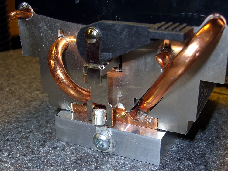
    A bit of futzing converted a pair of solderless connectors into clips that capture the hooks on the ends of the heatsink’s springy wiffletree to secure the spreader to the heatsink. You can see the flycut surface peeking out from below the end of the heatsink. I should hit it with some fine abrasive to polish it out, but I think heatsink compound alone will do the trick.
    Heat spreader on heatsink
    Heat spreader on heatsink

    The next step: drilling-and-tapping eight more blind holes along the sides for the FETs. It’d be really neat to have a servo spindle…

  • Improved Tour Easy Chain Tensioner

    A discussion on that post reminded me of this old project: replacing the chain pulleys in the midships chain tensioner on my Tour Easy recumbent.

    The problem is that the original pulleys used steel bearings in a plastic race, for reasons that I cannot fathom. They last for a few thousand miles, then get very wobbly and noisy. The solution, as nearly as I can tell, is to replace them with pulleys using cartridge bearings.

    This is what one looks like after four years slung below my bike. Surprisingly, the bearings still feel just fine, even though they’re not really sealed against the weather.

    Tour Easy - Cartridge Bearing Chain Tensioner
    Tour Easy – Cartridge Bearing Chain Tensioner

    Gotcha: the OEM pulleys are not the same OD / number of teeth as pulleys found in rear derailleurs.

    Soooo, after a bit of Quality Shop Time, I had these…

    Tour Easy Replacement Idler Pulley
    Tour Easy Replacement Idler Pulley

    This is where you really want an additive machining process, as I turned most of a big slab of aluminum into swarf while extracting each pulley.

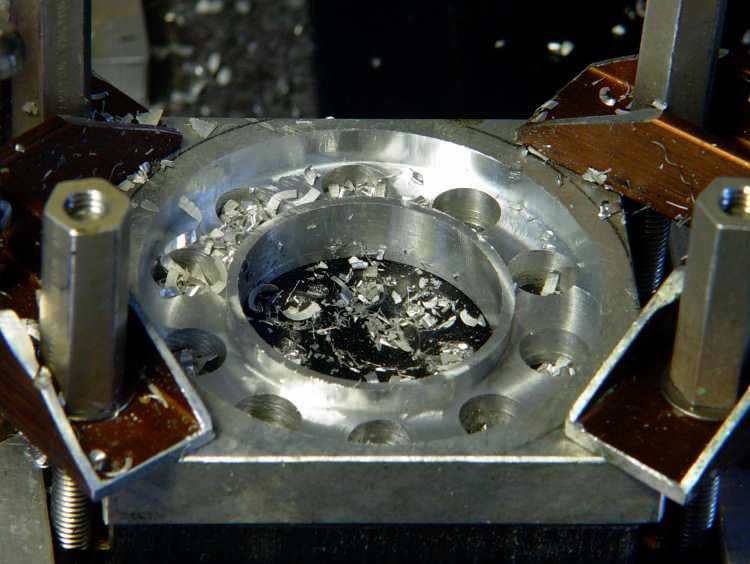
    The first step is to drill holes around the perimeter where the chain rollers will fit, plus drill out as much of the center bore as possible. Then mill down to the finished thickness across the roller holes and helix-mill the bore to size.

    Side 1
    Side 1

    Flip it over and mill the other side to the proper thickness.

    Run it through the bandsaw to chop off all the material beyond the outer diameter.

    Grab what’s left in the three-jaw chuck and mill around the perimeter to get a nice clean edge.

    Side 2
    Side 2

    And then it Just Works. I made another for Mary’s bike, but she said it was too noisy (which is why they used plastic rather than aluminum) and I swapped it for a Terracycle idler.

    This is from back in the Bad Old Days before EMC2’s version of G-Code supported loops. You don’t need to see that code, trust me on this.

  • External Li-Ion Pack Intermittent Connection: Dismantling the Pack

    The power lead into the Li-Ion pack I’m using for the bike radio became badly intermittent on a recent ride. When I got back I swapped in a different pack and the problem Went Away, but I noticed that the coaxial power plug didn’t seem to seat all the way into the jack on the failed pack. I’d noticed that before, although I attributed it to getting two different sets of the packs; it didn’t seem to make any difference.

    Given that I was going to have to either repair or replace the jack, dismantling the offending pack was next on the list. Some preliminary poking showed that there were no screws concealed under the label, so the two halves of the pack were either snapped or bonded together.

    The case didn’t respond to the usual wedging and prying by revealing an opening, which suggested that it was bonded. That meant I must saw the thing apart.

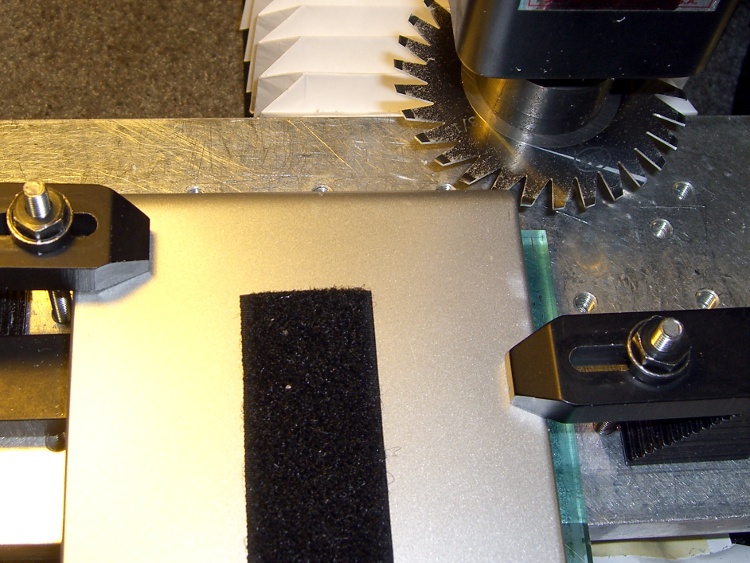
    I set up a 31-mil slitting saw on the Sherline and clamped the pack atop a random plastic slab atop the tooling plate. The Sherline’s limited throat depth meant I had to cut the far side of the pack. I aligned the saw to the Z-axis level of the joint along the middle of the pack by eyeballometric guesstimation.

    Slitting saw setup
    Slitting saw setup

    Key point:

    • You absolutely do not want to saw into a lithium-ion cell, not even a little bit.

    Therefore:

    • The pack must be aligned parallel to the cutter’s travel
    • The cuts must proceed in tiny increments, and
    • You must verify that each cut doesn’t reveal any surprises.

    In this setup, the pack aligns against a clamp on the left side and to a parallel block (removed while cutting) along the rear edge of the tooling plate. I could then unclamp the pack, rotate it to put the next edge in place, and use the same XYZ origin with the edge parallel to X.

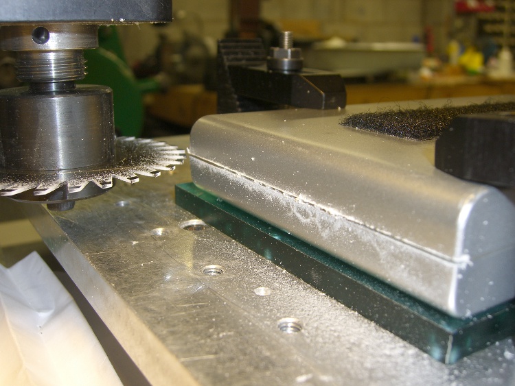
    Here’s the view from the back of the table.

    Sawing the case
    Sawing the case

    I ran the spindle at 5 k RPM and cut about 15 inch/secminute. I’m sure the pros do it faster, but that was enough to warm up the blade and that’s fast enough for me. [Update: typo on the units. Thanks!]

    Cuts were 0.020 inch per pass, which is about 0.5 mm. I expected the case to be some hard-metric dimension and wasn’t disappointed.

    After the cuts reached 0.060 inch, I manage to pry the remaining plastic in the joint apart and split the halves apart along the connectors and LEDs at the front where I couldn’t do any sawing.

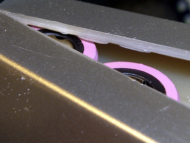
    Here’s a close look at the cut, just above the battery terminals. The case turned out to be 2 mm thick, about 0.080 inch, so I was just about all the way through. The cut was perfectly aligned with the case and cracked open neatly along the entire length.

    Tight tolerance on the cut depth
    Tight tolerance on the cut depth

    An interior view, showing that the cells adhered to the left half of the case and the electronics to the right: of course. I pried the cells loose from the left side, which provided enough access to unsolder the things, as the terminals were against the case. Notice that there’s absolutely nothing between the inside of the case and the outside of the cell, so cutting just slightly too deep would be a Bad Thing™.

    First look inside the case
    First look inside the case

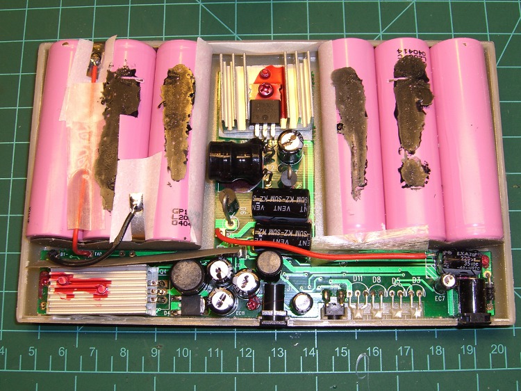
    After a bit of work, here’s the entire layout…

    Battery pack internal layout
    Battery pack internal layout

    Much to my surprise, the battery consists of two series-connected sets of three cells: 2 x 3.7 V = 7.4 V. I expected three series sets for about 3 x 3.7 = 11.1 V, with a linear regulator down to the 9.0 V output.

    As it turns out, they used two switching regulators: the one between the two triplets controls the charging voltage and the one to the lower-left boosts the battery to the pack’s 9.0 V output. I had hoped for a resistor divider that I could tweak to get 9.6 V out, but it certainly wasn’t obvious.

    I unsoldered the cells, dismounted the circuit board, and puzzled over it for a bit, after which the problem was obvious.

    The story continues tomorrow, with a dramatic denouement…

  • Pin Spanner for 3.5 mm Audio Jack Nut

    The external antenna jack on the Totally Featureless Clock is, by necessity, recessed way down in a hole (because I can’t get to the inside of the now-finished half-inch-thick case to gnaw it out from there). Perforce, that puts the locking nut out of reach.

    Solution: a pin spanner wrench. I’m sure they’re available commercially, but what’s the fun in that?

    The male threaded part of the jack is 0.230 inch OD, the nut is 0.313 OD, and the notches are 0.030 wide and 0.020 deep. Raw material is about two inches of 5/16-inch air-hardening drill rod, not that I’m actually going to heat treat it for this application.

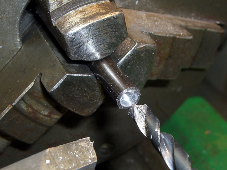
    Face off the end and drill the guts out with a 15/64-inch drill.

    Drilling central recess
    Drilling central recess

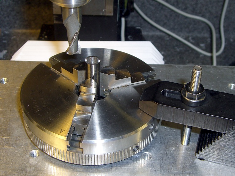
    Grab it in the 3-jaw chuck bolted firmly to the table, then mill off anything that isn’t a pin. Don’t grab it in the milling vise, which doesn’t have enough oomph to hold a slick steel cylinder in place; don’t ask how I know this.

    Milling pins in 3-jaw chuck
    Milling pins in 3-jaw chuck

    Set Z=0 at the top surface of the spanner-to-be and XY = 0 on the axis of the cylinder, of course.

    Manual CNC, feeding the commands into EMC2’s MDI slot and then mouse-clicking the stored commands to avoid reduce typing errors. For my setup, Y=±0.171 to produce the 30-mil pin and  X=±0.4 to clear on both sides.

    After cutting the first side at 3 k RPM, feed 2 inches/min, and 10 mils per pass, I whacked the other side off in one giant 20-mil bite. I’m such a sissy…

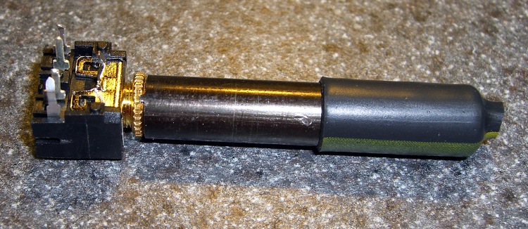
    A bit of heatshrink tubing improves the griptivity and it’s all good.

    Finished spanner engaged in nut
    Finished spanner engaged in nut

    This is the sort of thing you do once, drop in the baggie with the rest of the connector nuts, and use for years thereafter. I should’a done it years ago, but I’ve been able to not quite butcher the nuts with a needle-nose pliers…

    [Update: It turns out a commercial nut driver was available, at least in one special shop in one special place, but no longer. For my delicate uses, that shaft into the jack isn’t really needed.]

  • Sherline CNC Mill: Limited Headroom Thereof

    Cramped Headroom
    Cramped Headroom

    I had to drill a 1/4-inch hole in the Totally Featureless Clock’s case for the antenna jack. Fortunately, I have a 1/4-inch collet, because there was nowhere near enough room for the Jacobs chuck in there.

    Removing the tooling plate wouldn’t help: the chuck setup needed another inch!

    In truth, the headroom is rarely the limiting factor. Another inch or two of throat distance and maybe that much more Y travel would be nicer, while we’re at it.

    Ah, well, it’s all a matter of tradeoffs. If the mill were much bigger, I’d just want to make bigger projects, right?

  • IRQ Troubles on Razor

    The Dell Dimension 4560, a.k.a. razor, that controls my Sherline CNC mill woke up without network support. That’s a showstopper, because all the G-Code files live on the server across the basement.

    All my boxes have a network function dipstick test: the desktop background is an image on that same file server. When the NFS share wakes up dead, then the screen shows the default Ubuntu background: brown = down! (At least in Ubuntu 8.04 LTS, which is what EMC2 is built on right now.)

    Checklist…

    • NFS share isn’t mounted
    • … and can’t be mounted
    • ifconfig shows eth0 up & active
    • can’t ping the server
    • can’t ping razor from the server
    • Link lights on network switch nailed to floor joist overhead are green
    • Link light on NIC on back panel
    • Activity lights on switch & NIC blink occasionally (??)
    • Swapping ports on the switch = no change
    • Laptop works fine plugged into switch = switch OK

    So whatever is busted, is busted in the 4560. Drat!

    (Should have checked cable between switch and NIC. Sometimes you get a data failure without affecting the link & activity lights. Weird, but stuff happens.)

    Looking in dmesg shows that a bogus IRQ 11 occurred during startup:

    [   44.439932] irq 11: nobody cared (try booting with the  irqpoll" option)
    ... time passes ...
    ... bad IRQ log dump gibberish ...
    [   44.440440] Disabling IRQ #11
    

    Fairly obviously, after that point nothing about the NIC or anything else on IRQ 11 will work: the hardware setup may be OK, you can write to it and read from it, but no actual data gets through.

    A reboot didn’t cure the problem. Reboots in Linux rarely solve a problem; you’ve got to actually find the root cause and fix it, rather than shake the dice to see if a better combination comes up.

    Anyhow.

    Restarted to get into Dell’s attenuated BIOS configuration routine, changed the NIC to IRQ 3 (just because it was first on the list), saved, restarted, and everything works. The bogus interrupt is gone, the NIC is running, NFS shares are OK.

    It absolutely beats me. But at least this is written down so the next time it happens, I’ll remember what I did.

    Oh, yeah. The Sherline CNC mill uses stepping motors and uses cutters, so it’s a Steppin’ Razor, of course, and is therefore named razor. I suppose I could have called it molly, but that’d be a stretch.

  • HT GPS + Audio: Battery Pack Contacts the CNC Way

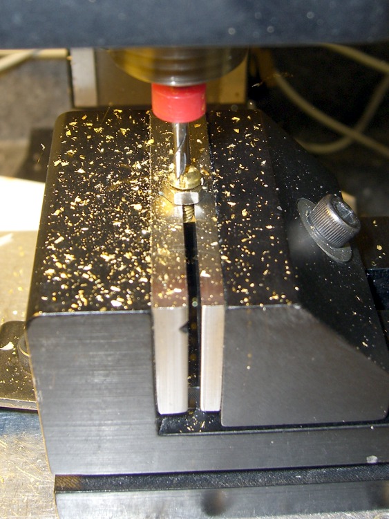
    Flattening the screw head
    Flattening the screw head

    Faced with the daunting prospect of converting half a dozen 4-40 brass screws into battery contacts by hand filing, I did what I should have done in the first place: turn it into a CNC project.

    It’s quick-n-easy:

    • mill the head flat and 0.5 mm thick
    • shave off the sides

    I grabbed the screw in the Sherline vise, touched off XY on the head (close enough to being concentric for this purpose), and touched off Z on the nut supporting the screw. For the next few, I’ll eyeball the Z touchoff at the bottom of the head, rather than the nut, because the heads don’t quite sit flush on the nut.

    They dropped right into place, without any filing or fiddling! Well, the second one did. I had to tweak the dimensions slightly to make the answer come out right. But that’s one of the advantage of hammering out simple G-Code like this: change two lines and wham you’re done.

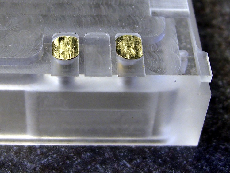
    Contacts in place
    Contacts in place

    The heads show some tool marks, but that’ll just make the silver solder stick better. Right?

    Herewith, the G-Code…

    (ICOM IC-Z1A battery pack shell)
    (Battery pack contacts)
    (Ed Nisley - KE4ZNU - June 2010)
    (Vise clamping on threads, XY orgin on central axis, Z=0 at *bottom* of screw head)
    (Tool table used just for Axis previews and to activate "manual" changer via M6)
    (Tool change @ G30 position above length probe)
    
    (-- Global dimensions & locations)
    
    #<_Traverse_Z> =        5.0
    #<_Cutting_Z> =            0.0
    
    (-- Get started ...)
    
    G40 G49 G54 G80 G90 G92.1 G94 G97 G98        (reset many things)
    
    M5
    (msg,Verify XY=0 on screw axis)
    M0
    
    (msg,Verify tool touched off at Z=0 on *bottom* of head)
    M0
    
    (debug,Verify vise clearance around head)
    M0
    
    #<Contact_Width> =        4.1            (X axis metallic contact - minus a smidge)
    #<Contact_Head_Dia> =    5.5            (recess for 4-40 head)
    #<Contact_Head_Radius> = [#<Contact_Head_Dia> / 2]
    
    #<Contact_Head_Depth> =    0.7            (recess depth - plus  smidge)
    
    #<Mill_Dia> =            1.98            (end mill diameter)
    #<Tool_Num> =            20
    #<Mill_Radius> =        [#<Mill_Dia> / 2]
    #<Mill_RPM> =            5000
    #<Mill_Feed> =             50
    
    (debug,Verify #<Mill_Dia> mm end mill)
    M0
    
    (debug,Set spindle to #<Mill_RPM>)
    M0
    
    F#<Mill_Feed>
    
    (--- Flatten the head)
    
    G0 Z#<_Traverse_Z>
    
    #<X_Step> = [0.5 * #<Mill_Dia>]
    #<X_Limit> = [3 * #<Mill_Radius>]
    #<Y_Limit> = [#<Contact_Head_Radius> + #<Mill_Radius>]
    
    #<X_Coord> = [0 - #<X_Limit>]
    
    G0 X#<X_Coord> Y[0 - #<Y_Limit>]
    G0 Z#<Contact_Head_Depth>
    
    O<Head_Trim> DO
    
    G1 Y#<Y_Limit>
    #<X_Coord> = [#<X_Coord> + #<X_Step>]
    G1 X#<X_Coord>
    G1 Y[0 - #<Y_Limit>]
    #<X_Coord> = [#<X_Coord> + #<X_Step>]
    G1 X#<X_Coord>
    
    O<Head_Trim> WHILE [#<X_Coord> LT [3 * #<Mill_Radius>]]
    
    G0 Z#<_Traverse_Z>
    
    (--- Trim the sides)
    
    #<Arc_Radius> = [#<Contact_Head_Radius>]
    #<Half_Width> = [#<Contact_Width> / 2]
    #<Angle> = ACOS [#<Half_Width> / #<Arc_Radius>]
    #<Half_Height> = [#<Arc_Radius> * SIN [#<Angle>]]
    
    G0 Z#<_Traverse_Z>
    
    G0 X[0 - #<Half_Width>] Y[0 - #<Contact_Head_Radius> - 3 * #<Mill_Dia>]
    G0 Z#<_Cutting_Z>
    
    G41.1 D#<Mill_Dia>
    G1 X[0 - #<Half_Width>] Y[0 - #<Half_Height>]
    
    G1 Y#<Half_Height>
    G2 X#<Half_Width> I[#<Half_Width>] J[-#<Half_Height>]
    G1 Y[0 - #<Half_Height>]
    G2 X[0 - #<Half_Width>] I[-#<Half_Width>] J[#<Half_Height>]
    G1 Y#<Half_Height>
    
    G0 Z#<_Traverse_Z>
    
    G40
    
    G30                    (back to tool change position)
    
    (msg,Done!)
    M2