The Smell of Molten Projects in the Morning

Ed Nisley's Blog: Shop notes, electronics, firmware, machinery, 3D printing, laser cuttery, and curiosities. Contents: 100% human thinking, 0% AI slop.

Tag: CNC

Making parts with mathematics

  • Logitech Dual Action Gamepad as EMC2 Pendant

    Gamepad Pendant
    Gamepad Pendant

    Just got this working and it’s downright slick!

    The general idea:

    The Hat jogs X and Y at the current maximum speed.

    The Left Knob jogs X and Y proportionally to the Knob displacement.

    The Right Knob jogs Z (Up-Down) and A (Left-Right) proportionally to the Knob displacement.

    Press either Knob downward to toggle the maximum jog speed between MAX_LINEAR_VELOCITY (as defined in the Sherline.ini file) and 5% of that value. The slow speed is useful for creeping up on alignment points: the first active level of the joysticks runs at a nose-pickin’ pace.

    The left little button (labeled 9) switches to Manual mode, although the AXIS display does not update to indicate this. Same as “F3” on keyboard, minus the GUI update.

    The right little button (labeled 10) continues a G-Code program by activating the Resume function. Same as “S” on the keyboard.

    The Mode button switches the functions of the Hat and Left Knob. That button does not generate an output and the Mode cannot be controlled programmatically. Swapping those functions doesn’t seem particularly useful in this application, so the LED should never be ON.

    Buttons 1-4 are not used for anything yet.

    On the back:

    • Pressing the left-hand pair of buttons (labeled 5 and 7) activates E-stop. Yes, I know all about why you shouldn’t have E-stop run through software. This is a Sherline mill. Work with me here.
    • The right-hand buttons (labeled 6 and 8) do nothing yet.

    The code…

    In Sherline.ini:

    [HAL]
    HALUI=halui
    

    In custom.hal:

    loadusr -W hal_input -KA Dual
    

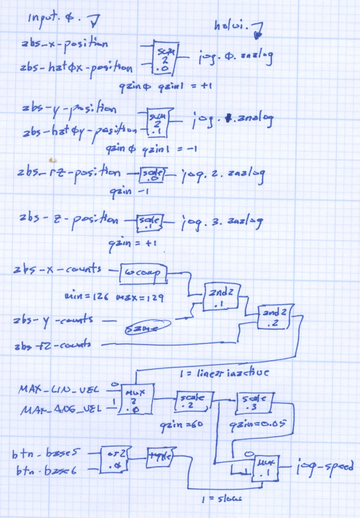
    All the heavy lifting happens in custom_postgui.hal. As nearly as I can tell, HAL is basically a write-only language, so there’s block diagram of the major chunks of “circuitry” down at the bottom.

    First, some setup and the simple buttons:

    #--------------
    # Logitech Dual Action joypad
    
    loadrt	and2 count=3
    loadrt	conv_s32_float count=3
    loadrt	mux2 count=2
    loadrt	or2 count=1
    loadrt	scale count=4
    loadrt	sum2 count=2
    loadrt	toggle count=1
    loadrt	wcomp count=3
    
    #-- central buttons activate manual mode and restart the program
    
    net 	mode-manual		input.0.btn-base3		halui.mode.manual
    
    net		pgm-resume		input.0.btn-base4		halui.program.resume
    
    #-- left-hand rear buttons active estop
    
    addf	and2.0 servo-thread
    
    net		pgm-estop-0		input.0.btn-base		and2.0.in0
    net		pgm-estop-1		input.0.btn-top2		and2.0.in1
    net		pgm-estop		and2.0.out				halui.estop.activate
    

    Because the Left Knob and Hat will never be active at the same time, a sum2 block combines the two controls into single value (separate for X and Y, of course). Each sum2 input has a separate gain setting, which is a convenient place to adjust the Y axis sign.

    #-- left knob runs XY at variable rate
    #   hat runs XY at full throttle
    
    addf	sum2.0 servo-thread
    
    net		x-jog-knob		input.0.abs-x-position		sum2.0.in0
    setp	sum2.0.gain0	+1.0
    net		x-jog-hat		input.0.abs-hat0x-position	sum2.0.in1
    setp	sum2.0.gain1	+1.0
    net		x-jog-total		sum2.0.out				halui.jog.0.analog
    
    addf	sum2.1 servo-thread
    
    net		y-jog-knob		input.0.abs-y-position		sum2.1.in0
    setp	sum2.1.gain0	-1.0
    net		y-jog-hat		input.0.abs-hat0y-position	sum2.1.in1
    setp	sum2.1.gain1	-1.0
    net		y-jog-total		sum2.1.out				halui.jog.1.analog
    

    The Right Knob values go through scale blocks to adjust the polarity. Note that the Gamepad’s rz axis controls the EMC2 Z axis and Gamepad z controls the EMC2 A axis. Basically, it made more sense to have up-down control Z and left-right control A.

    #-- right knob runs Z at variable rate (front-back)
    #                   A                 (left-right)
    
    addf	scale.0 servo-thread
    
    net		z-jog-knob		input.0.abs-rz-position		scale.0.in
    setp	scale.0.gain	-1
    
    net		z-jog-total		scale.0.out				halui.jog.2.analog
    
    addf	scale.1 servo-thread
    
    net		a-jog-knob		input.0.abs-z-position		scale.1.in
    setp	scale.1.gain	+1
    
    net		a-jog-total		scale.1.out				halui.jog.3.analog
    

    There’s only a single halui.jog-speed setting, but the jog speeds for the linear axes and the angular axes differ by so much that Something Had To Be Done. As above, I assumed that only one of the axes would be jogging at any one time, so I could set halui.jog-speed to match the active axis.

    A window comparator on each linear axis detects when the joystick is off-center; the output is 1 when the axis is centered and 0 when it’s pushed. Combining those three signals with and2 gates gives a combined linear-inactive signal.

    A mux2 block selects the MAX_ANGULAR_VELOCITY from the ini file when linear-inactive = 1 (linear not active) and MAX_LINEAR_VELOCITY when it is 0 (any linear axis off-center).

    Done that way, rather than detecting when the angular axis is off-center, means that inadvertently activating the angular axis during a linear jog doesn’t suddenly boost the linear speed. Given that the max linear is about 28 inch/minute and the max angular is 2700 degree/min, it’s a pretty abrupt change.

    I’m thinking about adding + shaped gates to at least the Right Knob so I can’t inadvertently activate both Z and A. I’m sure there’s a HAL lashup to do the same thing, though.

    #-- set jog speed by toggle from either knob button
    #   press any knob button to toggle
    
    addf	and2.1 servo-thread
    addf	and2.2 servo-thread
    addf	conv-s32-float.0 servo-thread
    addf	conv-s32-float.1 servo-thread
    addf	conv-s32-float.2 servo-thread
    addf	mux2.0 servo-thread
    addf	mux2.1 servo-thread
    addf	or2.0 servo-thread
    addf	scale.2 servo-thread
    addf	scale.3 servo-thread
    addf	toggle.0 servo-thread
    addf	wcomp.0 servo-thread
    addf	wcomp.1 servo-thread
    addf	wcomp.2 servo-thread
    
    #-- determine if any linear knob axis is active
    
    net		x-jog-count-int	input.0.abs-x-counts	conv-s32-float.0.in
    net		x-jog-count-raw	conv-s32-float.0.out	wcomp.0.in
    setp	wcomp.0.min		126
    setp	wcomp.0.max		128
    net		x-jog-inactive	wcomp.0.out				and2.1.in0
    
    net		y-jog-count-int	input.0.abs-y-counts	conv-s32-float.1.in
    net		y-jog-count-raw	conv-s32-float.1.out	wcomp.1.in
    setp	wcomp.1.min		126
    setp	wcomp.1.max		128
    net		y-jog-inactive	wcomp.1.out				and2.1.in1
    
    net		xy-active		and2.1.out				and2.2.in0
    
    net		rz-jog-count-int	input.0.abs-rz-counts	conv-s32-float.2.in
    net		rz-jog-count-raw	conv-s32-float.2.out	wcomp.2.in
    setp	wcomp.2.min		126
    setp	wcomp.2.max		128
    net		z-jog-inactive	wcomp.2.out				and2.2.in1
    
    #-- convert ini file unit/sec to unit/min and scale for slow jog
    
    setp	mux2.0.in0 [TRAJ]MAX_LINEAR_VELOCITY
    setp	mux2.0.in1 [TRAJ]MAX_ANGULAR_VELOCITY
    net		linear-inactive	and2.2.out				mux2.0.sel
    

    The ini file velocities are in units/second, so a scale block multiplies by 60 to get units/minute.

    Another scale block multiplies by 0.05 to get slow-speed jogging. Obviously, that value is a matter of taste: tune for best picture.

    Those two values go into a mux2 driven by the output of a toggle triggered by the or2 of the two buttons under the Knobs. Pushing either Knob down flips the toggle.

    setp	scale.2.gain	60
    net		jog-per-sec		mux2.0.out				scale.2.in
    net		jog-per-min		scale.2.out				mux2.1.in0
    net		jog-per-min		scale.3.in
    
    setp	scale.3.gain	0.05
    net		jog-per-min-slow scale.3.out			mux2.1.in1
    
    net		xy-button		input.0.btn-base5		or2.0.in0
    net		za-button		input.0.btn-base6		or2.0.in1
    net		xyza-button		or2.0.out				toggle.0.in
    
    net		xyza-slowmode	toggle.0.out			mux2.1.sel
    
    net		axis-jog-speed	mux2.1.out				halui.jog-speed
    

    When the jog speed is at the maximum allowed, it still gets trimmed by the per-axis limits, so you can’t over-rev the motors no matter how hard you try. Even better, changing the values in the ini file automagically affect the gamepad jog speeds.

    Now, to make some chips!

    The block diagram; click for a bigger image.

    HAL Gamepad Block Diagram
    HAL Gamepad Block Diagram
  • EMC2 HAL Pin Names: Logitech Dual Action Gamepad

    Here are the pin names for a Logitech Dual Action USB (wired) gamepad, according to EMC2 2.3.4. You’ll need these to wire it up as a control pendant for your EMC2 CNC milling machine…

    Front View
    Front View

    From /proc/bus/input/devices we find:

    I: Bus=0003 Vendor=046d Product=c216 Version=0110
    N: Name="Logitech Logitech Dual Action"
    P: Phys=usb-0000:00:1d.1-2/input0
    S: Sysfs=/devices/pci0000:00/0000:00:1d.1/usb2/2-2/2-2:1.0/input/input2
    U: Uniq=
    H: Handlers=event2 js0
    B: EV=1b
    B: KEY=fff 0 0 0 0 0 0 0 0 0
    B: ABS=30027
    B: MSC=10
    

    That tells us to use:

    halrun
    loadusr -W hal_input -KRA Dual
    loadusr halmeter
    

    There’s no need for -KRAL because it has no programmable LEDs.

    Prefix all these with input.0. to get the complete name.

    Hat Left-Right abs-hat0x-counts
    abs-hat0x-position
    Hat Up-Down abs-hat0y-counts
    abs-hat0y-position
    Hat Push none
    Left Knob Left-Right abs-x-counts
    abs-x-position
    Left Knob Up-Down abs-y-counts
    abs-y-position
    Left Knob Push btn-base5
    Right Knob Left-Right abs-z-counts
    abs-z-position
    Right Knob Up-Down abs-rz-counts
    abs-rz-position
    Right Knob Push btn-base6
    Button 1 btn-trigger
    Button 2 btn-thumb
    Button 3 btn-thumb2
    Button 4 btn-top
    Button 5 btn-top2
    Button 6 btn-pinkie
    Button 7 btn-base
    Button 8 btn-base2
    Button 9 btn-base3
    Button 10 btn-base4
    Mode button swap Hat & Left Knob
    lights red LED

    All of the buttons have -not output pins.

    The Knob position values run from -1.0 to +1.0 (float) and rest (almost) at 0.0 when centered. Their counts (s32) run from 0 to 255 and rest at 127 when centered.

    The Hat button position values are only -1.0 and +1.0, centered at 0.0. The counts are only -1 and +1, with 0 when un-pushed. Although they take on only integer values, the position values are floats.

    Both Knobs and the Hat have -Y position values at the top and +Y values at the bottom, exactly backwards from what you want. Expect to reverse the Y axis sign when you write the HAL code.

    The -X position values are to the left, where you want them.

    Although there’s a tactile click when pushing the Hat straight down, there is no corresponding button output. I don’t know if this is an oversight in the HAL interface or if there’s no actual switch in there.

    The Mode button swaps the Hat and Left Knob functions. With the red LED on, both the Hat and Knob axes produce only -1 and +1 position and counts values.

    A guide to figuring this stuff out is there, with useful pointers elsewhere on the main doc page.

    Tomorrow: turning it into an EMC2 pendant.

  • Acrylic Sheet Thickness Variations

    Milling plate thickness
    Milling plate thickness

    So I measured the thickness of the black acrylic sheet I’m using for the Totally Featureless clock and machined the rabbets to match. Went to assemble everything and the rabbets are too shallow!

    Come to find out that the sheet varies in thickness from about 0.437 to 0.475 across the four pieces I’d cut and, of course, I’d measured the thinnest end of the thinnest piece. Makes no sense to me, as I’d expect the thickness to be pretty well controlled over a few feet of sheet, but that’s not how things went down.

    The simplest solution was to mill a flat on the inside of the case to match the rabbet, so all four panel ends were the same thickness. The sketch below has the straight dope.

    Acrylic sheet thickness fix
    Acrylic sheet thickness fix

    Milling with a 3/8-inch end mill at 2500 rpm, 10 ipm, in one pass with no cooling was OK.

    I’ll insert some brass shimstock into the rabbets to make the outside edges wind up flush.

  • Sherline: Milling a Too-long Rabbet

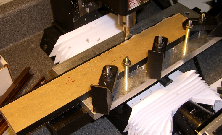
    This is pretty much the same general idea and setup as the one I described there, but with the panel flat against the tooling plate.

    Milling rabbet on top panel
    Milling rabbet on top panel

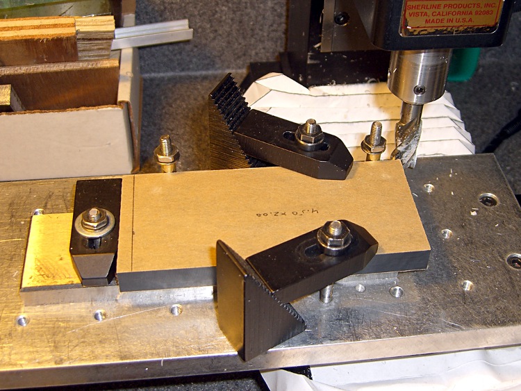
    The cutter sits at the far right end of its maximum travel. I made the rabbet in three manual CNC passes.

    To set up for the rest of the cut:

    • G0 X-4.25 to clear the left end of the panel
    • Loosen the three clamps, slide the panel leftward
    • Push the panel against the brass tubes
    • Tighten the clamps

    And away we go…

    Complete rabbet
    Complete rabbet

    One disadvantage: you can’t do a final finishing pass along the entire length of the cut. There are tool marks at the stopping point, but nothing really objectionable on the back of a clock where a panel will cover the rather ugly guts.

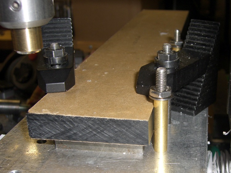
    The brass tube “locating pins” work surprisingly well.

    About 2000 rpm with 3/8 inch end mill. Cut 1/8 inch wide and 0.25 inch deep @ 10 ipm in three passes. Finish pass 15 ipm at 0.257 deep to make it pretty.

  • Sherline: Milling the Ends of Too-long Acrylic Panels

    Having flycut the acrylic panels to the proper width, I had to cut them to the proper length, too. This picture shows the lashup I used to hold them down during the operation…

    Clock top panel fixture
    Clock top panel fixture

    The brown bar sticking out to the left is one of the bookshelf struts that held the toolmaker’s vises down during the flycutting; it’s now secured to the Sherline table with a T-nut. A vise clamped to the bar serves as an end stop for the panels.

    Brass tubing locating posts
    Brass tubing locating posts

    A pair of brass tubes around studs serve as locating pins. To get the things lined up:

    • Loosely clamp a panel down atop a spacing plate
    • Push it back against the loose tubes: crudely parallel to X axis
    • Snug the clamps
    • Align the panel to the X axis using the laser
    • Push the tubes against the panel
    • Tighten their nuts
    Top panel end trimming detail
    Top panel end trimming detail

    Crude, but good enough for this purpose.

    Then a bit of manual CNC to shave off the end. Half-inch mill, 1500 rpm, 150 mm/min, more-or-less 0.5 mm cuts. The panels don’t have to be any exact length, as long as the clock circuit boards fit inside, but the ends must be perpendicular and smooth for good gluing.

    The exact part will come when I rabbet the side panels…

    The side panel setup was much simpler: same brass posts, same spacer, no need for the long bar hanging off to the left.

    Side panel fixturing
    Side panel fixturing
  • Sherline: Flycutting Too-Long Acrylic Panels

    Flycutting acrylic top panel
    Flycutting acrylic top panel

    The Totally Featureless Clock will have a black acrylic case with a Graylite Lexan faceplate. The top & bottom panels are 11.75 inches long, which is much too large for the Sherline’s 9-inch maximum X travel.

    Fortunately, in this case I can cheat.

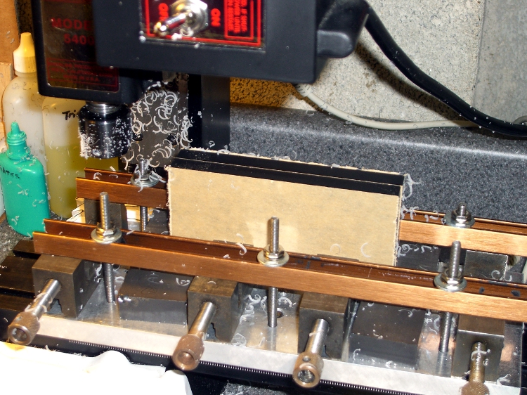
    This setup cut the panels to the proper width. A pair of parallel blocks, made from some mysterious glass-like material and ground very nicely flat, support the panel just over the body of the four toolmaker’s vises lined up along the tooling plate. I drilled the brown bookshelf rails to match the tooling plate and secured them with 10-32 studs.

    The front rail secures the vise bodies to the tooling plate; they’re aligned parallel to the X axis by the simple expedient of laying a parallel along the back edge and matching that to the tooling plate. No real precision is in order here; the flycut is across the whole top edge.

    The rear rail holds the movable vise jaws down; they tend to rise up just slightly when tightened, but the difference amounts to barely enough to release pressure on the parallel blocks. Not enough to matter, as it turned out.

    The general notion is to flycut about 2/3 of the length of the panel, then slide it far enough to cut the remainder. Flip it over and flycut the other side the same way.

    About 1000 rpm and 150 mm /min, cutting 0.5 mm or so on each pass.

    This worked surprisingly well. I expected to find a bow in the middle due to an uneven bandsaw cut on the initial downward side, but it was all good; evidently the blocks were wide enough to average things out.

    The joint where the two cuts meet turns out to be visible, but barely detectable with a fingernail: entirely suitable for this application. I’ll hit the sides with  sandpaper on a sheet of plate glass before bonding them  to the faceplate.

    Flycutting the end panels was much simpler: one pass clears their entire length. I moved the clamping rails to simplify the whole process; turned out that clamping the movable jaw didn’t really gain very much at all while complexicating the slide-the-stock process beyond belief.

    Flycutting end panels
    Flycutting end panels

    Overall, the width varies by about two mils along the length of the long panels and they’re perfectly straight as measured against a surface plate. Definitely close enough!

  • Cutting Pin Header Strips

    Slitting dual-row connector
    Slitting dual-row connector

    I needed a few strips of single-row pin headers, but the parts bin was empty.

    I hate it when that happens.

    The heap disgorged a handful of double-row strips and, of course, I Have A Machine Shop.

    So: no problem.

    This is, I admit, not cost-effective, but it took about 15 minutes to slit the aforementioned handful of strips right down the middle and get back to soldering.

    The trick is to use an ultra-thin slitting saw, rather than a regular saw. The one here is 4 mils thick and the better part of 7/8″ in diameter; call it 0.1 mm x 22 mm. I think it came with one of the Dremel tool kits a long while ago.

    Cut about 1 mm deep on the first pass, then cut through on the return to avoid having the saw deflect too much. Run about 100 mm/min, 1000 rpm, and no coolant. Line it up by eye, type manual CNC commands into EMC2, and it’s all good.

    The trick is finding a mandrel that doesn’t collide with the vise; my larger saws have a rather thick screw-and-washer arrangement that doesn’t fit. I think some padding (chopped-up credit cards?) between the longer pins, mounting the vise vertically, and grabbing the longer pins would fix that. The catch might be clearance between the top of the vise and the bottom of the spindle motor.

    Better to just buy some single-row strips. Sheesh… but if all you have is a CNC mill, you have plenty of solutions.

    Another slitting saw repair is there