Ed Nisley's Blog: Shop notes, electronics, firmware, machinery, 3D printing, laser cuttery, and curiosities. Contents: 100% human thinking, 0% AI slop.
This relay-like object appeared while shoveling off the Electronics Workbench. Most likely, it started life in the white-goods world, where recurring cost is everything:
Original relay
Now, doesn’t that look just like a tool length probe? It’s certainly less hideous than the one that’s been working fine on my Sherline mill, ever since I figured out how to make tool length probing work.
Here’s what caught my eye:
Plenty of switch overtravel
Nice metal bracket with screws
All the vital pieces in one convenient assembly!
Some brute force removed the spring and actuator, a few shots with a chisel broke the adhesive holding the coil in place, and this collection of parts emerged relatively unscathed:
Disassembled relay parts
Another shot with a pin punch removed the post from the frame. I intended to un-bend the L-shaped feature that held the post, enlarge the hole, and screw it to the mill. Alas, they formed the angle by notching the steel and it cracked when I un-bent it. No great loss.
The two bumps on the frame held the (now defunct) restoring spring. I simply filed those off while cleaning up the broken edges.
Drill a 10-32 clearance hole, solder a cable with a 3.5 mm stereo plug to the switch, add a plastic cable clamp, screw it to the end of the tooling plate, and it’s all good. That’s the butt end of a broken 2 mm end mill poking down from the spindle…
A G-Code routine that displays the Z-axis coordinate where the switch trips looks like this:
(Tool length probing test)

(--------------------)
( Initialize first tool length at probe switch)
(    Assumes G59.3 is still in machine units, returns in G54)
( ** Must set these constants to match G20 / G21 condition!)

#<_Probe_Speed> =        400            (set for something sensible in mm or inch)
#<_Probe_Retract> =        1            (ditto)

O<Probe_Tool> SUB

G49                     (clear tool length compensation)
G30                     (move above probe switch)
G59.3                   (coord system 9)

G38.2 Z0 F#<_Probe_Speed>           (trip switch on the way down)
G0 Z[#5063 + #<_Probe_Retract>]     (back off the switch)
G38.2 Z0 F[#<_Probe_Speed> / 10]    (trip switch slowly)

#<_ToolZ> = #5063                    (save new tool length)
G43.1 Z[#<_ToolZ> - #<_ToolRefZ>]    (set new length)

G54                     (coord system 0)
G30                     (return to safe level)

O<Probe_Tool> ENDSUB

(-------------------)
(-- Initialize first tool length at probe switch)

O<Probe_Init> SUB

#<_ToolRefZ> = 0.0      (set up for first call)
O<Probe_Tool> CALL
#<_ToolRefZ> = #5063    (save trip point)

G43.1 Z0                (tool entered at Z=0, so set it there)

O<Probe_Init> ENDSUB

(--------------------)
( Set up length)

G21                     ( metric units)

(msg,Verify G30.1 above tool change switch, hit Resume)
M0
(msg,Verify blunt tool installed, hit Resume)
M0

O<Probe_Init> CALL

(debug,Initial Z trip = #<_ToolRefZ>)

O100 REPEAT [10]

O<Probe_Tool> CALL
#<DeltaZ> = [#<_ToolZ> - #<_ToolRefZ>]
(debug,Z trip=#<_ToolZ> DeltaZ=#<_DeltaZ>)

O100 ENDREPEAT

M2
Notice that the results have six figures after the decimal point, but they’re really less precise: you’ll find four pairs of duplicates, which seems highly unlikely. I think the values are quantized to about 25 µ-inch and displayed as whatever the metric equivalent might be.
The corresponding plot looks like this:
Probe Repeatability
The trend line is highly suspect, but the slope shows that the trip point gets lower by one wavelength of violet light (393 microns) per trip. The total difference is a whopping 0.004 mm during the test, call it 160 millionth of an inch.
Both of those are better, by roughly a factor of two, than the previous probe switch.
Bottom line: That’s OK for the sort of machining I do… ship it!
This is a stick in the ground for the current config files I’m using with EMC 2.4.5. Even the automagically generated files may have some tweakage, which is why I’m putting them here…
[Update: this is for a Dell Dimension 4550 with a latency around 10 µs, occasional glitches to 20 µs, and a very rare burp to 80 µs. Worked fine, but those rare burps were disturbing.]
# Include your customized HAL commands here
# This file will not be overwritten when you run stepconf again

#--------------
# Get buttons and joysticks from Logitech Dual Action gamepad

loadusr -W hal_input -KA Dual

#--------------
# Home switches are all in parallel, active low

net homeswitches <= parport.0.pin-10-in-not
net homeswitches => axis.0.home-sw-in
net homeswitches => axis.1.home-sw-in
net homeswitches => axis.2.home-sw-in

#--------------
# Probe input is active low

net probe-in <== parport.0.pin-15-in-not
net probe-in ==> motion.probe-input
custom_postgui.hal
#-- empty
Logitech_Gamepad.hal
# HAL config file automatically generated by Eagle-CAD ULP:
# [/mnt/bulkdata/Project Files/eagle/ulp/hal-write-array.ulp]
# (C) Martin Schoeneck.de 2008
# Mods Ed Nisley 2010
# Path        [/mnt/bulkdata/Project Files/eagle/projects/EMC2 HAL Configuration/]
# ProjectName [Logitech Gamepad]
# File name   [/mnt/bulkdata/Project Files/eagle/projects/EMC2 HAL Configuration/Logitech_Gamepad.hal]
# Created     [11:51:27 10-Nov-2010]

####################################################
# Load realtime and userspace modules
loadrt constant		count=16
loadrt and2		count=17
loadrt flipflop		count=4
loadrt mux2		count=5
loadrt mux4		count=1
loadrt not		count=8
loadrt or2		count=10
loadrt scale		count=7
loadrt timedelay		count=1
loadrt toggle		count=1
loadrt wcomp		count=6

####################################################
# Hook functions into threads
addf toggle.0		servo-thread
addf wcomp.1		servo-thread
addf wcomp.2		servo-thread
addf wcomp.3		servo-thread
addf and2.0		servo-thread
addf and2.4		servo-thread
addf and2.3		servo-thread
addf and2.2		servo-thread
addf and2.1		servo-thread
addf constant.6		servo-thread
addf constant.5		servo-thread
addf constant.4		servo-thread
addf constant.3		servo-thread
addf constant.2		servo-thread
addf constant.1		servo-thread
addf constant.0		servo-thread
addf constant.7		servo-thread
addf constant.8		servo-thread
addf scale.1		servo-thread
addf scale.2		servo-thread
addf scale.3		servo-thread
addf mux4.0		servo-thread
addf mux2.0		servo-thread
addf scale.4		servo-thread
addf scale.0		servo-thread
addf wcomp.5		servo-thread
addf wcomp.4		servo-thread
addf wcomp.0		servo-thread
addf flipflop.1		servo-thread
addf flipflop.0		servo-thread
addf and2.5		servo-thread
addf and2.6		servo-thread
addf and2.7		servo-thread
addf and2.8		servo-thread
addf flipflop.2		servo-thread
addf flipflop.3		servo-thread
addf or2.4		servo-thread
addf or2.8		servo-thread
addf or2.7		servo-thread
addf or2.6		servo-thread
addf or2.5		servo-thread
addf or2.3		servo-thread
addf or2.2		servo-thread
addf or2.1		servo-thread
addf or2.0		servo-thread
addf not.1		servo-thread
addf not.2		servo-thread
addf not.3		servo-thread
addf not.4		servo-thread
addf not.5		servo-thread
addf not.6		servo-thread
addf not.7		servo-thread
addf not.0		servo-thread
addf constant.9		servo-thread
addf mux2.1		servo-thread
addf mux2.2		servo-thread
addf mux2.3		servo-thread
addf mux2.4		servo-thread
addf constant.10		servo-thread
addf constant.11		servo-thread
addf scale.5		servo-thread
addf scale.6		servo-thread
addf constant.12		servo-thread
addf constant.13		servo-thread
addf timedelay.0		servo-thread
addf constant.14		servo-thread
addf constant.15		servo-thread
addf and2.16		servo-thread
addf and2.15		servo-thread
addf and2.14		servo-thread
addf and2.13		servo-thread
addf and2.12		servo-thread
addf and2.11		servo-thread
addf and2.10		servo-thread
addf and2.9		servo-thread
addf or2.9		servo-thread

####################################################
# Set parameters

####################################################
# Set constants
setp constant.0.value	+0.02
setp constant.1.value	-0.02
setp constant.2.value	60
setp constant.3.value	1.00
setp constant.4.value	0.10
setp constant.5.value	0.50
setp constant.6.value	0.10
setp constant.7.value	+0.5
setp constant.8.value	-0.5
setp constant.9.value	0.0
setp constant.10.value	[TRAJ]MAX_LINEAR_VELOCITY
setp constant.11.value	[TRAJ]MAX_ANGULAR_VELOCITY
setp constant.12.value	-1.0
setp constant.13.value	0.1
setp constant.14.value	0.020
setp constant.15.value	0.000

####################################################
# Connect Modules with nets
net a-button-minus input.0.btn-trigger or2.2.in0 and2.15.in0
net a-button-plus input.0.btn-thumb2 or2.2.in1 and2.16.in0
net a-buttons-active or2.2.out or2.3.in0 or2.4.in1
net a-disable not.7.out and2.5.in1
net a-enable or2.4.in0 flipflop.3.out not.7.in mux2.4.sel
net a-jog wcomp.2.in input.0.abs-z-position mux2.4.in1
net a-knob-active not.2.out and2.7.in1
net a-knob-inactive wcomp.2.out not.2.in and2.6.in1
net a-select and2.8.in0 and2.7.out
net a-set flipflop.3.set and2.8.out
net angular_motion or2.4.out mux2.0.sel
net any-buttons-active mux4.0.sel0 or2.8.out
net az-buttons-active or2.3.out or2.8.in1 or2.9.in0
net az-reset flipflop.2.reset and2.6.out flipflop.3.reset
net button-crawl scale.4.out mux4.0.in3
net button-fast scale.2.out mux4.0.in1 scale.4.in
net jog-crawl toggle.0.out mux4.0.sel1
net jog-speed halui.jog-speed mux4.0.out
net knob-crawl mux4.0.in2 scale.3.out
net knob-fast mux4.0.in0 scale.1.out scale.3.in
net n_1 constant.10.out mux2.0.in0
net n_2 and2.0.in0 input.0.btn-top2
net n_3 and2.0.in1 input.0.btn-base
net n_4 and2.0.out halui.abort
net n_5 halui.mode.manual input.0.btn-base3
net n_6 wcomp.0.max wcomp.1.max wcomp.2.max wcomp.3.max constant.0.out
net n_7 halui.program.resume input.0.btn-base4
net n_8 wcomp.0.min wcomp.1.min wcomp.2.min wcomp.3.min constant.1.out
net n_9 mux2.0.in1 constant.11.out
net n_10 constant.12.out scale.5.gain scale.6.gain
net n_11 input.0.btn-base5 or2.0.in0
net n_12 input.0.btn-base6 or2.0.in1
net n_13 constant.9.out mux2.1.in0 mux2.2.in0 mux2.3.in0 mux2.4.in0
net n_14 mux2.1.out halui.jog.0.analog
net n_15 toggle.0.in or2.0.out
net n_16 constant.2.out scale.0.gain
net n_17 constant.5.out scale.1.gain
net n_18 constant.3.out scale.2.gain
net n_19 constant.4.out scale.3.gain
net n_20 scale.4.gain constant.6.out
net n_21 halui.jog.1.analog mux2.2.out
net n_22 mux2.2.in1 scale.5.out
net n_23 scale.6.out mux2.3.in1
net n_24 constant.13.out halui.jog-deadband
net n_25 wcomp.4.max constant.7.out wcomp.5.max
net n_26 constant.8.out wcomp.4.min wcomp.5.min
net n_27 mux2.3.out halui.jog.2.analog
net n_28 halui.jog.3.analog mux2.4.out
net n_29 timedelay.0.out and2.9.in1 and2.10.in1 and2.12.in1 and2.11.in1 and2.13.in1 and2.14.in1 and2.16.in1 and2.15.in1
net n_30 and2.9.out halui.jog.0.minus
net n_31 or2.9.out timedelay.0.in
net n_32 constant.14.out timedelay.0.on-delay
net n_33 constant.15.out timedelay.0.off-delay
net n_34 and2.10.out halui.jog.0.plus
net n_35 and2.11.out halui.jog.1.minus
net n_36 halui.jog.1.plus and2.12.out
net n_37 and2.13.out halui.jog.2.minus
net n_38 and2.14.out halui.jog.2.plus
net n_39 and2.15.out halui.jog.3.minus
net n_40 and2.16.out halui.jog.3.plus
net vel-per-minute scale.0.out scale.1.in scale.2.in
net vel-per-second mux2.0.out scale.0.in
net x-buttons-active or2.7.in0 or2.5.out
net x-disable not.4.out and2.4.in1
net x-enable not.4.in flipflop.0.out mux2.1.sel
net x-hat-jog wcomp.4.in input.0.abs-hat0x-position
net x-hat-minus wcomp.4.under or2.5.in1 and2.9.in0
net x-hat-plus or2.5.in0 wcomp.4.over and2.10.in0
net x-jog wcomp.0.in input.0.abs-x-position mux2.1.in1
net x-knob-active not.0.out and2.1.in0
net x-knob-inactive wcomp.0.out not.0.in and2.2.in0 and2.3.in0
net x-set and2.1.out flipflop.0.set
net xy-buttons-active or2.7.out or2.8.in0 or2.9.in1
net xy-reset flipflop.0.reset and2.2.out flipflop.1.reset
net y-buttons-active or2.6.out or2.7.in1
net y-disable not.5.out and2.1.in1
net y-enable flipflop.1.out not.5.in mux2.2.sel
net y-hat-jog input.0.abs-hat0y-position wcomp.5.in
net y-hat-minus wcomp.5.under or2.6.in1 and2.12.in0
net y-hat-plus or2.6.in0 wcomp.5.over and2.11.in0
net y-jog wcomp.1.in input.0.abs-y-position scale.5.in
net y-knob-active not.1.out and2.3.in1
net y-knob-inactive not.1.in wcomp.1.out and2.2.in1
net y-select and2.4.in0 and2.3.out
net y-set flipflop.1.set and2.4.out
net z-button-minus input.0.btn-thumb or2.1.in0 and2.13.in0
net z-button-plus or2.1.in1 input.0.btn-top and2.14.in0
net z-buttons-active or2.1.out or2.3.in1
net z-disable not.6.out and2.8.in1
net z-enable not.6.in flipflop.2.out mux2.3.sel
net z-jog wcomp.3.in input.0.abs-rz-position scale.6.in
net z-knob-active not.3.out and2.5.in0
net z-knob-inactive not.3.in wcomp.3.out and2.7.in0 and2.6.in0
net z-set and2.5.out flipflop.2.set
Sherline.hal
# Generated by stepconf at Sat Aug 23 12:10:22 2008
# If you make changes to this file, they will be
# overwritten when you run stepconf again
loadrt trivkins
loadrt [EMCMOT]EMCMOT base_period_nsec=[EMCMOT]BASE_PERIOD servo_period_nsec=[EMCMOT]SERVO_PERIOD traj_period_nsec=[EMCMOT]SERVO_PERIOD key=[EMCMOT]SHMEM_KEY num_joints=[TRAJ]AXES
loadrt probe_parport
loadrt hal_parport cfg=0xecd8
setp parport.0.reset-time 60000
loadrt stepgen step_type=0,0,0,0
loadrt pwmgen output_type=0

addf parport.0.read base-thread
addf stepgen.make-pulses base-thread
addf pwmgen.make-pulses base-thread
addf parport.0.write base-thread
addf parport.0.reset base-thread

addf stepgen.capture-position servo-thread
addf motion-command-handler servo-thread
addf motion-controller servo-thread
addf stepgen.update-freq servo-thread
addf pwmgen.update servo-thread

net spindle-cmd <= motion.spindle-speed-out => pwmgen.0.value
net spindle-enable <= motion.spindle-on => pwmgen.0.enable
net spindle-pwm <= pwmgen.0.pwm
setp pwmgen.0.pwm-freq 100.0
setp pwmgen.0.scale 1166.66666667
setp pwmgen.0.offset 0.114285714286
setp pwmgen.0.dither-pwm true
net spindle-cw <= motion.spindle-forward

net estop-out => parport.0.pin-01-out
net xdir => parport.0.pin-02-out
net xstep => parport.0.pin-03-out
setp parport.0.pin-03-out-reset 1
setp parport.0.pin-04-out-invert 1
net ydir => parport.0.pin-04-out
net ystep => parport.0.pin-05-out
setp parport.0.pin-05-out-reset 1
setp parport.0.pin-06-out-invert 1
net zdir => parport.0.pin-06-out
net zstep => parport.0.pin-07-out
setp parport.0.pin-07-out-reset 1
net adir => parport.0.pin-08-out
net astep => parport.0.pin-09-out
setp parport.0.pin-09-out-reset 1
net spindle-cw => parport.0.pin-14-out
net spindle-pwm => parport.0.pin-16-out
net xenable => parport.0.pin-17-out

setp stepgen.0.position-scale [AXIS_0]SCALE
setp stepgen.0.steplen 1
setp stepgen.0.stepspace 0
setp stepgen.0.dirhold 60000
setp stepgen.0.dirsetup 60000
setp stepgen.0.maxaccel [AXIS_0]STEPGEN_MAXACCEL
net xpos-cmd axis.0.motor-pos-cmd => stepgen.0.position-cmd
net xpos-fb stepgen.0.position-fb => axis.0.motor-pos-fb
net xstep <= stepgen.0.step
net xdir <= stepgen.0.dir
net xenable axis.0.amp-enable-out => stepgen.0.enable

setp stepgen.1.position-scale [AXIS_1]SCALE
setp stepgen.1.steplen 1
setp stepgen.1.stepspace 0
setp stepgen.1.dirhold 60000
setp stepgen.1.dirsetup 60000
setp stepgen.1.maxaccel [AXIS_1]STEPGEN_MAXACCEL
net ypos-cmd axis.1.motor-pos-cmd => stepgen.1.position-cmd
net ypos-fb stepgen.1.position-fb => axis.1.motor-pos-fb
net ystep <= stepgen.1.step
net ydir <= stepgen.1.dir
net yenable axis.1.amp-enable-out => stepgen.1.enable

setp stepgen.2.position-scale [AXIS_2]SCALE
setp stepgen.2.steplen 1
setp stepgen.2.stepspace 0
setp stepgen.2.dirhold 60000
setp stepgen.2.dirsetup 60000
setp stepgen.2.maxaccel [AXIS_2]STEPGEN_MAXACCEL
net zpos-cmd axis.2.motor-pos-cmd => stepgen.2.position-cmd
net zpos-fb stepgen.2.position-fb => axis.2.motor-pos-fb
net zstep <= stepgen.2.step
net zdir <= stepgen.2.dir
net zenable axis.2.amp-enable-out => stepgen.2.enable

setp stepgen.3.position-scale [AXIS_3]SCALE
setp stepgen.3.steplen 1
setp stepgen.3.stepspace 0
setp stepgen.3.dirhold 60000
setp stepgen.3.dirsetup 60000
setp stepgen.3.maxaccel [AXIS_3]STEPGEN_MAXACCEL
net apos-cmd axis.3.motor-pos-cmd => stepgen.3.position-cmd
net apos-fb stepgen.3.position-fb => axis.3.motor-pos-fb
net astep <= stepgen.3.step
net adir <= stepgen.3.dir
net aenable axis.3.amp-enable-out => stepgen.3.enable

net estop-out <= iocontrol.0.user-enable-out
net estop-out => iocontrol.0.emc-enable-in

loadusr -W hal_manualtoolchange
net tool-change iocontrol.0.tool-change => hal_manualtoolchange.change
net tool-changed iocontrol.0.tool-changed <= hal_manualtoolchange.changed
net tool-number iocontrol.0.tool-prep-number => hal_manualtoolchange.number
net tool-prepare-loopback iocontrol.0.tool-prepare => iocontrol.0.tool-prepared
This is a proof-of-concept lashup for a camera-mounted spectrometer; I wanted to find out if the image processing would work, but needed some images without devoting a lot of time to the hardware.
The general idea is that a direct-view spectrometer produces a focused-at-infinity image for your eye. Substitute a camera for your eye and you get an image with the spectral components laid out in a spatial array, suitable for measurement and calculation.
The trick is holding the spectrometer on the lens axis while blocking ambient light. I figured that I could mount the spectrometer in a disk that fit into the camera’s 58 mm filter threads, then hold it in place for the few pix I’d need to get started.
The end result was Good Enough for the purpose, although it’s definitely a kludge…
Spectrometer mounted on camera
The (admittedly cheap) prism-based direct-view spectrometer has a slide-to-focus mechanism that substitutes heavy grease for mechanical precision. A guide screw in a slot prevents the focusing tube from rotating in the body tube, so I decided to replace that with a locking screw to clamp the tubes together. It’s a very fine thread, undoubtedly metric, screw, but a bit of rummaging in my teeny-screw drawer turned up a match (those are mm divisions on the scale):
Spectrometer screw vs standard thread
I think the spectroscope makers filed down the head of an ordinary brass screw to fit the slot, rather than using an actual fillister screw. That’s a Torx T-6 head on the flat-head screw, which probably came from a scrapped hard drive. I eventually found a round-head crosspoint screw (requiring a P-1 bit) that worked better, with a brass washer underneath for neatness.
That got me to this stage:
Spectrometer with locking screw
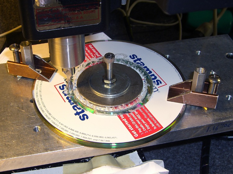
Making the adapter disk involved, as usual, a bit of manual CNC to enlarge the center hole of a CD from 15 to 15.75 mm, then cut out a 57 mm cookie. A stack of CDs makes a perfectly good sacrificial work surface for this operation, with some fender washers clamping the pile to the tooling plate. Those homebrew clamps are smaller than the Official Sherline clamps and work better for large objects on the small table.
Milling outside diameter
I briefly considered milling a thread into the OD, but came to my senses… I still have that pile of 10-32 taps, but now is not the time!
While in the Machine Tool Wing of the Basement Laboratory, I bored a short plastic bushing to a tight slip fit on the focusing tube to clamp the disk to the eyepiece, with the intent of keeping the eyepiece from whacking the camera lens. That’s the small white cylinder in the first picture.
As it turned out, I had to mount the whole affair on a sunshade that screwed into the camera filter mount, because the eyepiece protruded far enough to just barely kiss the lens.
A liberal covering of black electrical tape killed off all the stray light. Hand-holding all the pieces together and aiming it at the CFL tube over the Electronics Workbench produced this First Light image:
First light – warm-white CFL – no adjustments
Believe it or not, that’s pretty much in focus. Much of the width in the red & green lines seems to come from the phosphors, as there’s a bar-sharp narrow blue line to the far right, beyond the obvious blue line.
Settings: manual focus at infinity, manual exposure 1/60 @ f/2.4, auto ISO = 100. Maybe 30 cm from the 27 W CFL tube: way more light than I’ll ever get through a liquid sample in a cuvette.
Another pass at my Logitech Dual-Action Gamepad used as an EMC2 control pendant, but this time using an Eagle ULP (User Language Program) that converts a schematic into EMC2 HAL code.
I tweaked Martin Schöneck’s original ULP a bit, added (some of the) new devices found in EMC2.4, added the corresponding Eagle symbols & devices to the library, then drew up a schematic based on my hand-hewn HAL code with some improvements. Ran the script and shazam the HAL code worked just fine (after a bit of debugging the infrastructure, of course).
The new ULP and library are not quite ready for prime time, but this is a stick in the ground to mark some progress. You can certainly use the HAL code directly, without fiddling around in the schematic: stuff the whole program (at the end of the post) in your existing (but likely empty) custom_postgui.hal file.
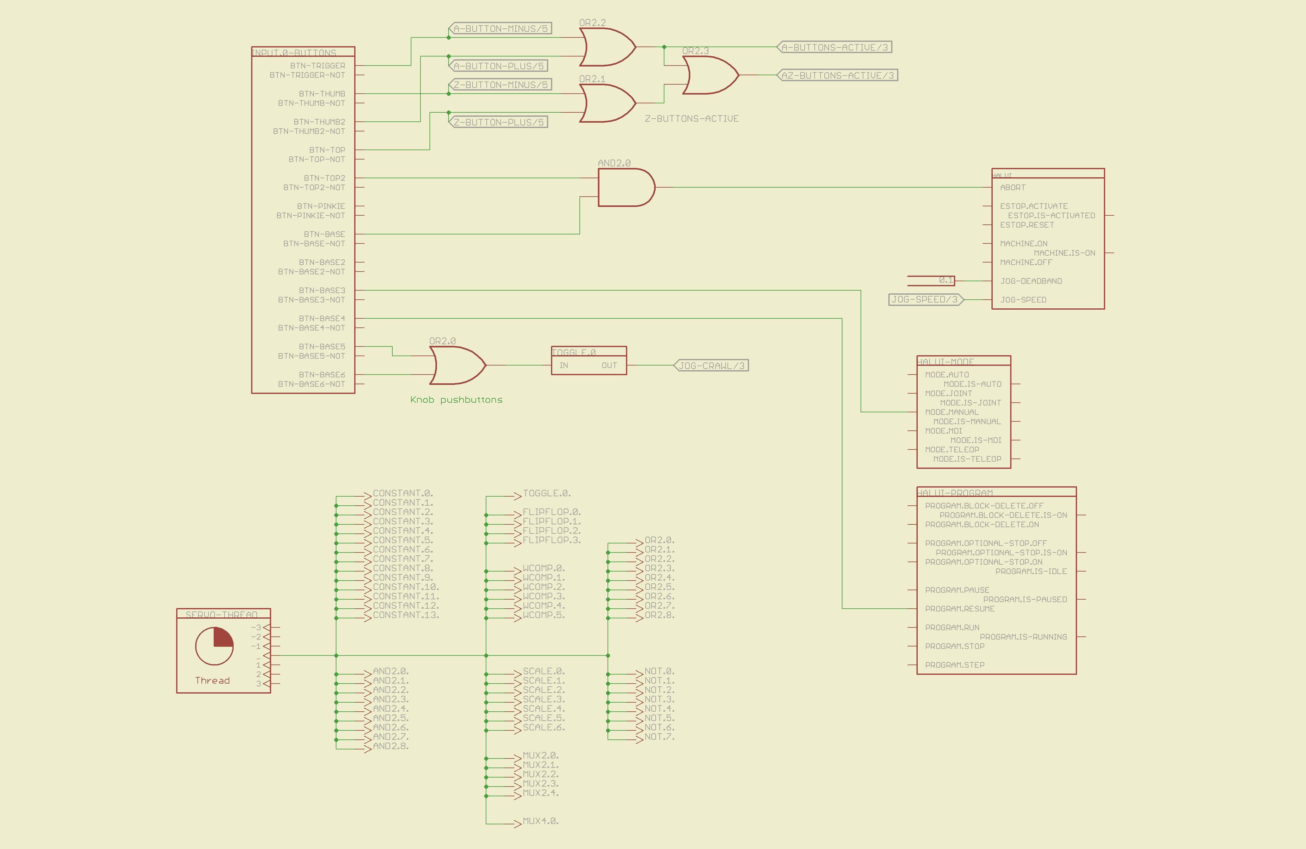
The schematic is, of course, much fluffier than the corresponding code, particularly because I chopped it into five easily printed pages. Here’s the Big Picture overview of what’s going on in each page; click the pix for bigger images.
The servo thread interface device in the lower left provides the halui timing. The big block in the upper left has all the Logitech gamepad buttons, including the four big ones used for Z and A axis jogging. I changed the two left-rear buttons to activate the Abort signal rather than Estop, not that I use them all that much anyway.
The two joystick knobs have pushbuttons, which I combine and use to toggle a flipflop that will select the jogging speed: fast or crawl.
I also cut the jog deadband from 0.2 to 0.1, which makes the joysticks much more responsive.
Logitech Gamepad HAL Schematic – Page 1
The big block on the left has all the gamepad’s analog axes. The HAT0X and HAT0Y axes correspond to the top-hat pushbuttons; they’re not really analog at all, although they take on -1.0 / 0.0 / + 1.0 floating point values. The window comparators determine which joystick axes are active, which comes in handy later on.
Logitech Gamepad HAL Schematic – Page 2
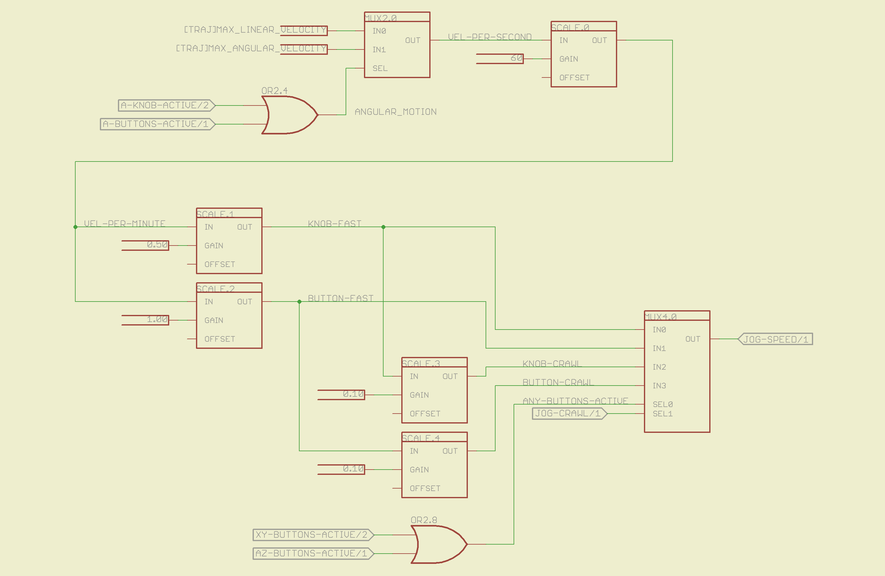
The HAL jogging control has a single input that sets the default speed, but the proper value is vastly different depending on whether you’re jogging with linear or angular motion. This page picks out which ini file MAX_VELOCITY value to use, converts from units/sec to units/min, then does Cool Thing #1: scales the speed so that the fast/crawl speeds work out nicely.
I use the buttons to jog rapidly from here to there, then creep up on the alignment point using the joysticks. Pressing the joysticks downward switches from Fast to Crawl speeds, which provides sort of a gearshift that’s useful for coarse / fine adjustments.
The buttons run at two speeds:
Fast: the maximum speed for the axis
Crawl: 10% of that value
The joysticks have a lower top speed:
Fast: half the maximum speed of the axis
Crawl: 10% of that value
All those values go into the mux4 block and thence to the HAL jog speed control.
Logitech Gamepad HAL Schematic – Page 3
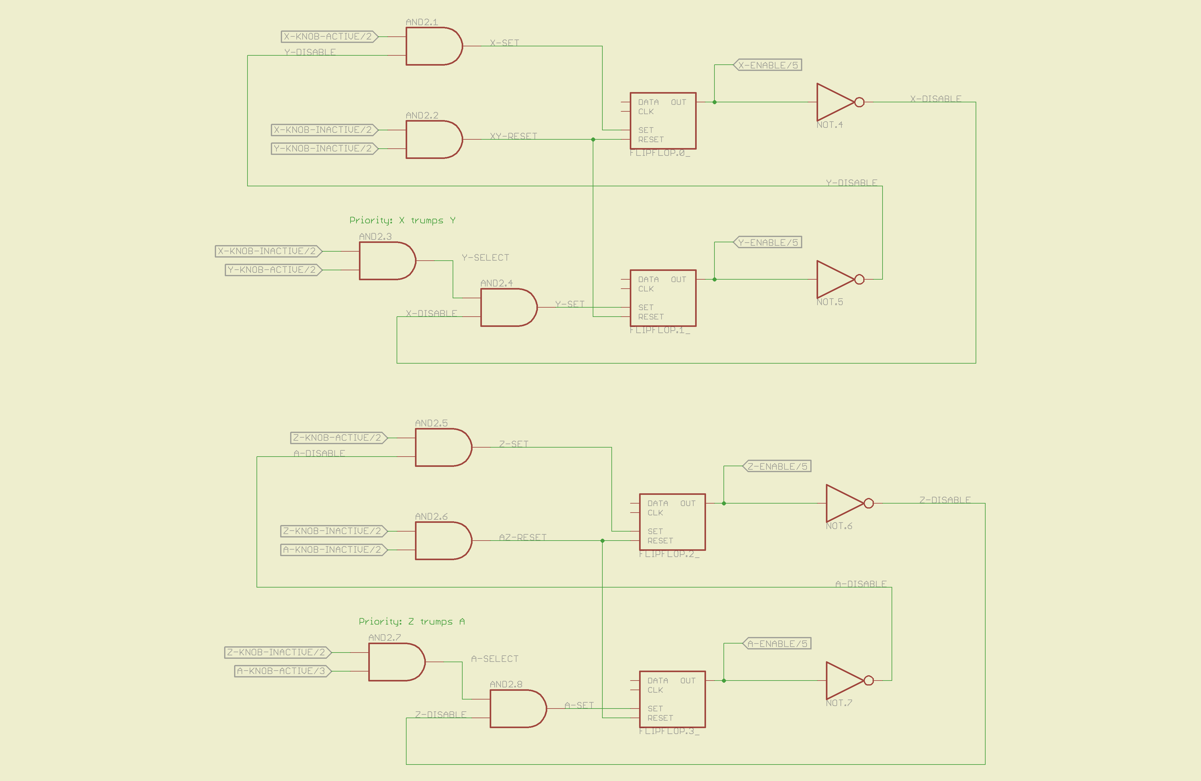
This page does Cool Thing #2: prioritize the joystick axes and lock out the one that started moving last. The general idea is that it’s painfully easy to move the joysticks diagonally, which is great for gaming and terrible for milling machine control. A pair of flipflops for each joystick remember which axis started moving first.
If you want to move diagonally, just press the buttons; they’re not locked out, so you can do what you want.
Logitech Gamepad HAL Schematic – Page 4
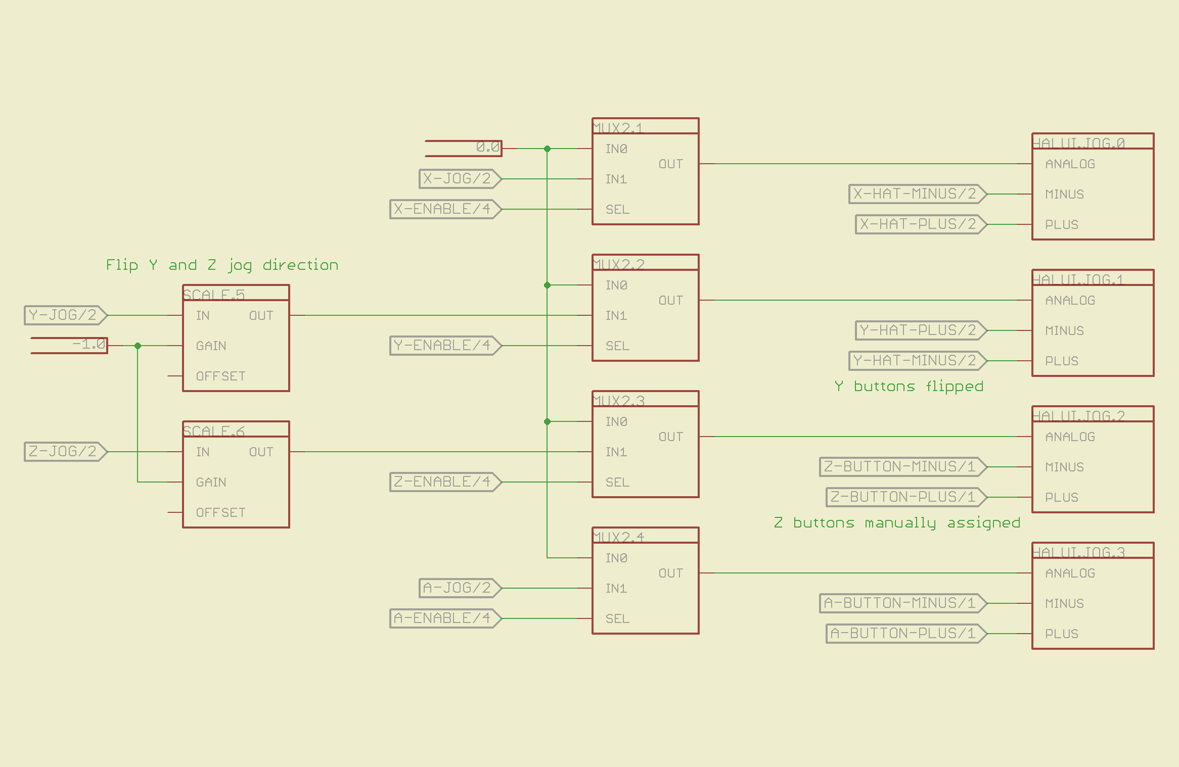
The motion comes together on the last page, where scale blocks flip the direction of the Y and Z joystick axes so positive motion is upward. The multiplexers allow only the active axis of each joystick to reach the HAL analog jog inputs; you can vary the speed of that axis up to the maximum as you’d expect. The buttons drive the digital inputs that jog at that maximum speed; the Y and Z button directions get sorted out appropriately.
Logitech Gamepad HAL Schematic – Page 5
Those five pages boil down into the following code, which I manually insert into my custom_postgui.hal file, along with the tool length probe pin definition.
# HAL config file automatically generated by Eagle-CAD hal-write.ulp
# (C) Martin Schoeneck.de 2008
# Mods Ed Nisley 2010

# Path: [/mnt/bulkdata/Project Files/eagle/projects/EMC2 HAL Configuration/]
# ProjectName: [Logitech Gamepad]
# File name: [/mnt/bulkdata/Project Files/eagle/projects/EMC2 HAL Configuration/Logitech Gamepad.hal]

####################################################
# Load realtime and userspace modules
loadrt constant	count=14
loadrt and2	count=9
loadrt flipflop	count=4
loadrt mux2	count=5
loadrt mux4	count=1
loadrt not	count=8
loadrt or2	count=9
loadrt scale	count=7
loadrt toggle	count=1
loadrt wcomp	count=6

####################################################
# Hook functions into threads
addf toggle.0	servo-thread
addf wcomp.1	servo-thread
addf wcomp.2	servo-thread
addf wcomp.3	servo-thread
addf and2.0	servo-thread
addf and2.4	servo-thread
addf and2.3	servo-thread
addf and2.2	servo-thread
addf and2.1	servo-thread
addf constant.6	servo-thread
addf constant.5	servo-thread
addf constant.4	servo-thread
addf constant.3	servo-thread
addf constant.2	servo-thread
addf constant.1	servo-thread
addf constant.0	servo-thread
addf constant.7	servo-thread
addf constant.8	servo-thread
addf scale.1	servo-thread
addf scale.2	servo-thread
addf scale.3	servo-thread
addf mux4.0	servo-thread
addf mux2.0	servo-thread
addf scale.4	servo-thread
addf scale.0	servo-thread
addf wcomp.5	servo-thread
addf wcomp.4	servo-thread
addf wcomp.0	servo-thread
addf flipflop.1	servo-thread
addf flipflop.0	servo-thread
addf and2.5	servo-thread
addf and2.6	servo-thread
addf and2.7	servo-thread
addf and2.8	servo-thread
addf flipflop.2	servo-thread
addf flipflop.3	servo-thread
addf or2.4	servo-thread
addf or2.8	servo-thread
addf or2.7	servo-thread
addf or2.6	servo-thread
addf or2.5	servo-thread
addf or2.3	servo-thread
addf or2.2	servo-thread
addf or2.1	servo-thread
addf or2.0	servo-thread
addf not.1	servo-thread
addf not.2	servo-thread
addf not.3	servo-thread
addf not.4	servo-thread
addf not.5	servo-thread
addf not.6	servo-thread
addf not.7	servo-thread
addf not.0	servo-thread
addf constant.9	servo-thread
addf mux2.1	servo-thread
addf mux2.2	servo-thread
addf mux2.3	servo-thread
addf mux2.4	servo-thread
addf constant.10	servo-thread
addf constant.11	servo-thread
addf scale.5	servo-thread
addf scale.6	servo-thread
addf constant.12	servo-thread
addf constant.13	servo-thread

####################################################
# Set parameters

####################################################
# Set constants
setp constant.0.value	+0.02
setp constant.1.value	-0.02
setp constant.2.value	60
setp constant.3.value	1.00
setp constant.4.value	0.10
setp constant.5.value	0.50
setp constant.6.value	0.10
setp constant.7.value	+0.5
setp constant.8.value	-0.5
setp constant.9.value	0.0
setp constant.10.value	[TRAJ]MAX_LINEAR_VELOCITY
setp constant.11.value	[TRAJ]MAX_ANGULAR_VELOCITY
setp constant.12.value	-1.0
setp constant.13.value	0.1

####################################################
# Connect Modules with nets
net a-button-minus input.0.btn-trigger or2.2.in0 halui.jog.3.minus
net a-button-plus input.0.btn-thumb2 or2.2.in1 halui.jog.3.plus
net a-buttons-active or2.2.out or2.3.in0 or2.4.in1
net a-disable not.7.out and2.5.in1
net a-enable flipflop.3.out not.7.in mux2.4.sel
net a-jog wcomp.2.in input.0.abs-z-position mux2.4.in1
net a-knob-active not.2.out or2.4.in0 and2.7.in1
net a-knob-inactive wcomp.2.out not.2.in and2.6.in1
net a-select and2.8.in0 and2.7.out
net a-set flipflop.3.set and2.8.out
net angular_motion or2.4.out mux2.0.sel
net any-buttons-active mux4.0.sel0 or2.8.out
net az-buttons-active or2.3.out or2.8.in1
net az-reset flipflop.2.reset and2.6.out flipflop.3.reset
net button-crawl scale.4.out mux4.0.in3
net button-fast scale.2.out mux4.0.in1 scale.4.in
net jog-crawl toggle.0.out mux4.0.sel1
net jog-speed halui.jog-speed mux4.0.out
net knob-crawl mux4.0.in2 scale.3.out
net knob-fast mux4.0.in0 scale.1.out scale.3.in
net n_1 constant.10.out mux2.0.in0
net n_2 and2.0.in0 input.0.btn-top2
net n_3 and2.0.in1 input.0.btn-base
net n_4 and2.0.out halui.abort
net n_5 halui.mode.manual input.0.btn-base3
net n_6 wcomp.0.max wcomp.1.max wcomp.2.max wcomp.3.max constant.0.out
net n_7 halui.program.resume input.0.btn-base4
net n_8 wcomp.0.min wcomp.1.min wcomp.2.min wcomp.3.min constant.1.out
net n_9 mux2.0.in1 constant.11.out
net n_10 constant.12.out scale.5.gain scale.6.gain
net n_11 input.0.btn-base5 or2.0.in0
net n_12 input.0.btn-base6 or2.0.in1
net n_13 constant.9.out mux2.1.in0 mux2.2.in0 mux2.3.in0 mux2.4.in0
net n_14 mux2.1.out halui.jog.0.analog
net n_15 toggle.0.in or2.0.out
net n_16 constant.2.out scale.0.gain
net n_17 constant.5.out scale.1.gain
net n_18 constant.3.out scale.2.gain
net n_19 constant.4.out scale.3.gain
net n_20 scale.4.gain constant.6.out
net n_21 halui.jog.1.analog mux2.2.out
net n_22 mux2.2.in1 scale.5.out
net n_23 scale.6.out mux2.3.in1
net n_24 constant.13.out halui.jog-deadband
net n_25 wcomp.4.max constant.7.out wcomp.5.max
net n_26 constant.8.out wcomp.4.min wcomp.5.min
net n_27 mux2.3.out halui.jog.2.analog
net n_28 halui.jog.3.analog mux2.4.out
net vel-per-minute scale.0.out scale.1.in scale.2.in
net vel-per-second mux2.0.out scale.0.in
net x-buttons-active or2.7.in0 or2.5.out
net x-disable not.4.out and2.4.in1
net x-enable not.4.in flipflop.0.out mux2.1.sel
net x-hat-jog wcomp.4.in input.0.abs-hat0x-position
net x-hat-minus wcomp.4.under or2.5.in1 halui.jog.0.minus
net x-hat-plus or2.5.in0 wcomp.4.over halui.jog.0.plus
net x-jog wcomp.0.in input.0.abs-x-position mux2.1.in1
net x-knob-active not.0.out and2.1.in0
net x-knob-inactive wcomp.0.out not.0.in and2.2.in0 and2.3.in0
net x-set and2.1.out flipflop.0.set
net xy-buttons-active or2.7.out or2.8.in0
net xy-reset flipflop.0.reset and2.2.out flipflop.1.reset
net y-buttons-active or2.6.out or2.7.in1
net y-disable not.5.out and2.1.in1
net y-enable flipflop.1.out not.5.in mux2.2.sel
net y-hat-jog input.0.abs-hat0y-position wcomp.5.in
net y-hat-minus wcomp.5.under or2.6.in1 halui.jog.1.plus
net y-hat-plus or2.6.in0 wcomp.5.over halui.jog.1.minus
net y-jog wcomp.1.in input.0.abs-y-position scale.5.in
net y-knob-active not.1.out and2.3.in1
net y-knob-inactive not.1.in wcomp.1.out and2.2.in1
net y-select and2.4.in0 and2.3.out
net y-set flipflop.1.set and2.4.out
net z-button-minus input.0.btn-thumb or2.1.in0 halui.jog.2.minus
net z-button-plus input.0.btn-top or2.1.in1 halui.jog.2.plus
net z-buttons-active or2.1.out or2.3.in1
net z-disable not.6.out and2.8.in1
net z-enable not.6.in flipflop.2.out mux2.3.sel
net z-jog wcomp.3.in input.0.abs-rz-position scale.6.in
net z-knob-active not.3.out and2.5.in0
net z-knob-inactive not.3.in wcomp.3.out and2.7.in0 and2.6.in0
net z-set and2.5.out flipflop.2.set
The ULP script that eats the schematic and poots out the HAL code:
/******************************************************************************
 * HAL-Configurator
 *
 * Author: Martin Schoeneck 2008
 * Additional gates & tweaks: Ed Nisley KE4ZNU 2010
 *****************************************************************************/
#usage "<h1>HAL-Configurator</h1>Start from a Schematic where symbols from hal-config.lbr are used!";

string output_path =    "./";
string dev_loadrt =     "LOADRT";
string dev_loadusr =    "LOADUSR";
string dev_thread =     "THREAD";
string dev_parameter =  "PARAMETER";

string dev_names[] = {
"CONSTANT",								// must be first entry to make set_constants() work
"ABS",				// 2.4
"AND2",
"BLEND",			// 2.4
"CHARGE-PUMP",		// 2.4
"COMP",
"CONV_S32_FLOAT",	// 2.4
"DDT",				// 2.4
"DEADZONE",			// 2.4
"DEBOUNCE",			// 2.4
"EDGE",
"ENCODER",			// 2.4
"ENCODER-RATIO",	// 2.4
"ESTOP-LATCH",
"FLIPFLOP",
"FREQGEN",			// 2.4
"LOWPASS",
"MULT2",			// 2.4
"MUX2",
"MUX4",				// 2.4
"MUX8",				// 2.4
"NEAR",				// 2.4
"NOT",
"ONESHOT",
"OR2",
"SAMPLER",			// 2.4
"SCALE",			// 2.4
"SELECT8",			// 2.4
"SUM2",
"TIMEDELAY",		// 2.4
"TOGGLE",			// 2.4
"WCOMP",			// 2.4
"XOR2",				// 2.4
""					// end flag
};

string init = "# HAL config file automatically generated by Eagle-CAD hal-write.ulp\n# (C) Martin Schoeneck.de 2008\n# Mods Ed Nisley 2010\n";

/*******************************************************************************
 * Global Stuff
 ******************************************************************************/

string FileName;
string ProjectPath;
string ProjectName;

void Info(string Message) {
	dlgMessageBox(";<b>Info</b><p>\n" + Message);
}

void Warn(string Message) {
	dlgMessageBox("!<b>Warning</b><p>\n" + Message + "<p>see usage");
}

void Error(string Message) {
	dlgMessageBox(":<hr><b>Error</b><p>\n" + Message + "<p>see usage");
	exit(1);
}

string replace(string str, char a, char b) {
	// in string str replace a with b
	int pos = -1;
	do {
		// find that character
		pos = strchr(str, a);
		// replace if found
		if(pos >= 0) {
			str[pos] = b;
		}
	} while(pos >= 0);

	return str;
}

// the part name contains an index and is written in capital letters
string get_module_name(UL_PART P) {
	// check module name, syntax: INDEX:NAME
	string mod_name = strlwr(P.name);
	// split string at the : if exists
	string a[];
	int c = strsplit(a, mod_name, ':');
	mod_name = a[c-1];
	// if name starts with '[' we need uppercase letters
	if(mod_name[0] == '[') {
		mod_name = strupr(mod_name);
	}

	return mod_name;
}

string comment(string mess) {
	string str = "\n\n####################################################\n";
	if(mess != "") {
		str += "# " + mess + "\n";
	}

	return str;
}

// if this is a device for loading a module, load it (usr/rt)
string load_module(UL_PART P) {
	string str = "";

	// it's a module if the device's name starts with LOADRT/LOADUSR
	if((strstr(P.device.name, dev_loadrt) == 0) ||
	   (strstr(P.device.name, dev_loadusr) == 0)) {

		// now add the string to our script
		str += P.value + "\n";
	}

	return str;
}

// count used digital gates (and, or, etc) and load module if neccessary
string load_blocks() {
	string str = "";

	int index;

	int dev_counters[];
	string dname[];

	// count the gates that are used
	schematic(S) { S.parts(P) {
		strsplit(dname,P.device.name,'.');		// extract first part of name
		if ("" != lookup(dev_names,dname[0],0)) {
			for (index = 0;  (dname[0] != dev_names[index]) ; index++) {
				continue;
			}
			dev_counters[index]++;
		}
	} }

// force lowercase module names...

	for (index = 0; ("" != dev_names[index]) ; index++) {
		if (dev_counters[index]) {
			sprintf(str,"%sloadrt %s\tcount=%d\n",str,strlwr(dev_names[index]),dev_counters[index]);
		}
	}

	return str;
}

string hook_function(UL_NET N) {
	string str = "";

	// is this net connected to a thread (work as functions here)?
	int    noclkpins       = 0;
	string thread_name     = "";  // this net should be connected to a thread
	string thread_position = "";
	N.pinrefs(PR) {
		// this net is connected to a clk-pin
		if(PR.pin.function == PIN_FUNCTION_FLAG_CLK) {
			// check the part: is it a thread-device?
			if(strstr(PR.part.device.name, dev_thread) == 0) {
				// we need the name of the thread
				thread_name = strlwr(PR.part.name);
				// and we need the position (position _ is ignored)
				thread_position = strlwr(PR.pin.name);
				thread_position = replace(thread_position, '_', ' ');
			}
		} else {
			// no clk-pin, this is no function-net
			noclkpins++;
			break;
		}
	}

	// found a thread?
	if(noclkpins == 0 && thread_name != "") {
		// all the other pins are interesting now
		N.pinrefs(PR) {
			// this pin does not belong to the thread
			if(strstr(PR.part.device.name, dev_thread) != 0) {
				// name of the pin is name of the function
				//string function_name = strlwr(PR.pin.name);
				string function_name = strlwr(PR.instance.gate.name);
				// if functionname starts with a '.', it will be appended to the modulename
				if(function_name[0] == '.') {
					// if the name is only a point, it will be ignored
					if(strlen(function_name) == 1) {
						function_name = "";
					}
					function_name = get_module_name(PR.part) + function_name;
				}
				str += "addf " + function_name + "\t" + thread_name + "\t" + thread_position + "\n";
			}
		}
	}

	return str;
}

string set_parameter(UL_NET N) {
	string str = "";

	// is this net connected to a parameter-device?
	int    nodotpins       = 0;
	string parameter_value = "";
	N.pinrefs(PR) {
		// this net is connected to a dot-pin
		if(PR.pin.function == PIN_FUNCTION_FLAG_DOT) {
			// check the part: is it a parameter-device?
//			str += "** dev name [" + PR.part.device.name + "] [" + dev_parameter + "]\n";
			if(strstr(PR.part.device.name, dev_parameter) == 0) {
				// we need the value of that parameter
				parameter_value = PR.part.value;
//				str += "**  value [" + PR.part.value +"]\n";
			}
		} else {
			// no clk-pin, this is no function-net
			nodotpins++;
			break;
		}
	}

	// found a parameter?
	if(nodotpins == 0 && parameter_value != "") {
		// all the other pins are interesting now
		N.pinrefs(PR) {
//			str += "** dev name [" + PR.part.device.name + "] [" + dev_parameter + "]\n";
			// this pin does not belong to the parameter-device
			if(strstr(PR.part.device.name, dev_parameter) != 0) {
				// name of the pin is name of the function
				//string parameter_name = strlwr(PR.pin.name);
				string parameter_name = strlwr(PR.instance.gate.name);
				// if functionname starts with a '.', it will be appended to the modulename
//				str += "** param (gate) name [" + parameter_name + "]\n";
				if(parameter_name[0] == '.') {
					// if the name is only a point, it will be ignored
					if(strlen(parameter_name) == 1) {
						parameter_name = "";
					}
					parameter_name = get_module_name(PR.part) + parameter_name;
//					str += "** param (part) name [" + parameter_name + "]\n";
				}
				str += "setp " + parameter_name + "\t" + parameter_value + "\n";
			}
		}
	}

	return str;
}

// if this is a 'constant'-device, set its value
// NOTE: this is hardcoded to use the first entry in the dev_names[] array!
string set_constants(UL_PART P) {
	string str = "";

	// 'constant'-device?
	if(strstr(P.device.name, dev_names[0]) == 0) {
		str += "setp " + get_module_name(P) + ".value\t" + P.value + "\n";
	}

	return str;
}

string connect_net(UL_NET N) {
	string str = "";

	// find all neccessary net-members
	string pins = "";
	N.pinrefs(P) {
		// only non-functional pins are connected
		if(P.pin.function == PIN_FUNCTION_FLAG_NONE) {
			string pin_name =  strlwr(P.pin.name);
			string part_name = strlwr(P.part.name);
			pin_name =  replace(pin_name,  '$', '_');
			part_name = replace(part_name, '$', '_');
			pins += part_name + "." + pin_name + " ";
		}
	}

	if(pins != "") {
		string net_name = strlwr(N.name);
		net_name = replace(net_name, '$', '_');
		str += "net " + net_name + " " + pins + "\n";
	}

	return str;
}

/*******************************************************************************
 * Main program.
 ******************************************************************************/
// is the schematic editor running?
if (!schematic) {
	Error("No Schematic!<br>This program will only work in the schematic editor.");
}

schematic(S) {
	ProjectPath = filedir(S.name);
	ProjectName = filesetext(filename(S.name), "");
}

// build configuration
string cs = init + "\n\n";

FileName = ProjectPath + ProjectName + ".hal";

cs += "# Path: [" + ProjectPath + "]\n";
cs += "# ProjectName: [" + ProjectName + "]\n";
//cs += "# File name: [" + FileName + "]\n\n";

// ask for a filename: where should we write the configuration?

FileName = dlgFileSave("Save Configuration", FileName, "*.hal");

if(!FileName) {
	exit(0);
}

cs += "# File name: [" + FileName + "]\n\n";

schematic(S) {
	// load modules
	cs += comment("Load realtime and userspace modules");
	S.parts(P) {
		cs += load_module(P);
	}

	// load blocks
	cs += load_blocks();

	// add functions
	cs += comment("Hook functions into threads");
	S.nets(N) {
		cs += hook_function(N);
	}

	// set parameters
	cs += comment("Set parameters");
	S.nets(N) {
		cs += set_parameter(N);
	}

	// set constant values
	cs += comment("Set constants");
	S.parts(P) {
		cs += set_constants(P);
	}

	// build nets and connect them
	cs += comment("Connect Modules with nets");
	S.nets(N) {
		cs += connect_net(N);
	}
}

// open/overwrite the target file to save the configuration
output(FileName, "wt") {
	printf(cs);
}
Most of that script is Martin’s work; I just cleaned it up. You can download it by hovering over the code to make the little toolbar pop up near the upper-right corner of the text, then:
click a little button to copy it to the clipboard or
click another little button to view the source, then save that file
You’ll also need the Eagle library that goes along with the script, but WordPress doesn’t like .lbr files. Here’s the hal-config-2.4.lbr file with a totally bogus odt extension. Download it, rename it to remove the .odt extension, and it’s all good.
There is basically no documentation for any of this. I figured out what to do by looking at the source and Martin’s sample schematic, but now you have two sample schematics: the situation is definitely improving!
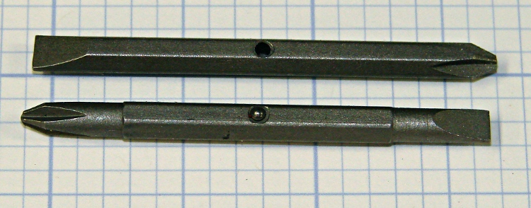
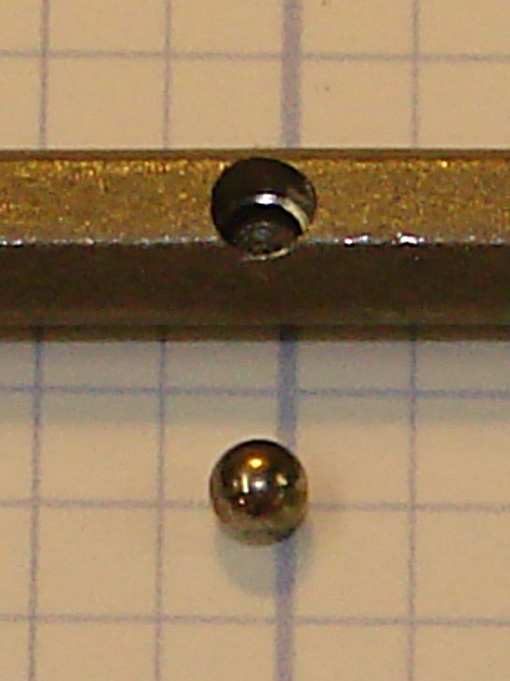
Went to use a small multi-bit screwdriver and the bit fell right out: evidently, the ball wasn’t swaged tightly enough; it and the spring went walkabout. Given that I don’t know when or where that might have happened, there’s no chance I’ll ever see those parts again.
Screwdriver bit with missing ball
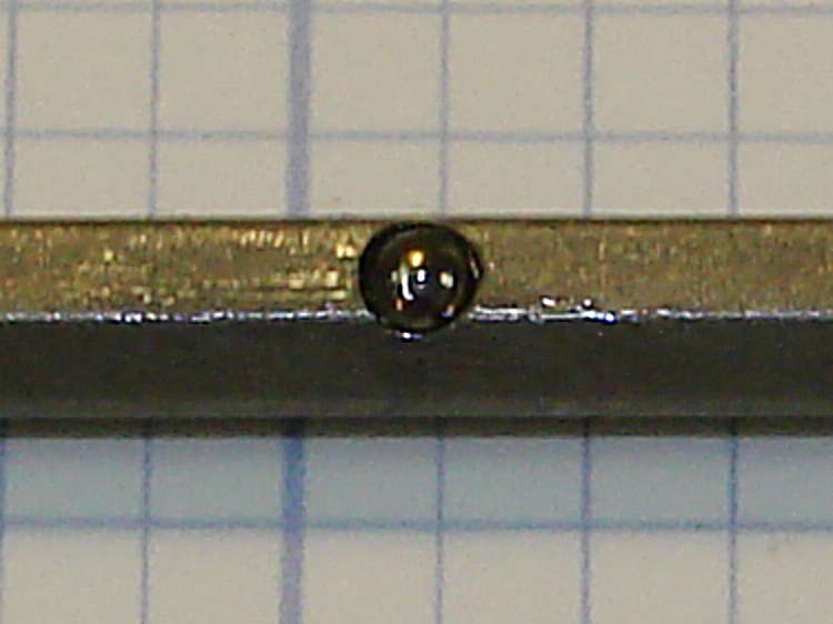
But I do have some 2 mm steel bearings that aren’t grossly oversized, so all hope is not lost. Alas, I have no idea what sort of spring to put in there, other than that I don’t have one of those.
Drilled hole with ball
This looks like an application for rubberdraulics: use compliant silicone snot rubber as a spring. Lautard described a use with a lock ring and an external screw to apply pressure, but here it’ll work fine to allow a small motion for a tiny ball.
Drill out the recess barely larger than the ball: the slight clearance allows the cured rubber to squish out around the ball. I clamped it in the Sherline vise and jogged into position by eyeball, then poked a hole with G83 down 1.5 mm. The original recess was a bit over 2 mm deep, so there’s plenty of room for the silicone in the bottom.
Then mush some silicone into the hole, install the ball, push it down until it stands barely proud of the surface, scrape off the excess rubber, and let it cure overnight.
Having successfully drilled and tapped eight 4-40 holes for the MOSFETs and two 8-32 holes for the heatsink clamps, I needed four more holes for the 6-32 standoffs that will mount the heat spreader to the base. As is always the case, the tap broke in the next-to-last hole…
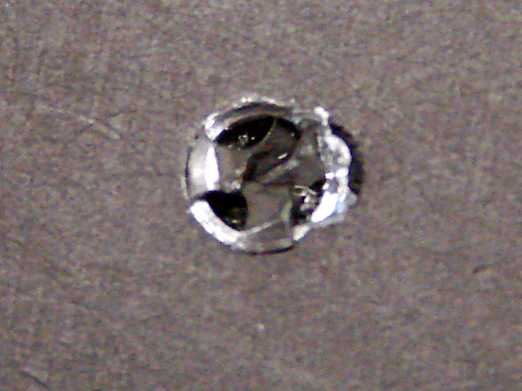
Broken tap
This is a three-flute tap, the break is recessed below the surface, and it looks like it’s cracked along one of the flutes. Bleh! I don’t have any tap extractors, mostly because I don’t do that much tapping, and I doubt the extractors work all that well on tiny taps.
I tried something I’d never done before: slit the top of the tap with an abrasive wheel and unscrew it. That didn’t work, of course, but it’s a useful trick to keep in mind. I think the tap was cracked lengthwise and, in any event, a three-flute tap doesn’t have the proper symmetry for a slot. Better luck with larger four-flute taps.
Slotted tap
So I must dig the mumble thing out…
Starting the moat
The overall plan:
Clamp the heat spreader to the Sherline tooling plate
Helix-mill a trench around the tap
Grab the stub with Vise-Grips
Unscrew it
Repair the damage
The clearance hole for a 6-32 screw is 0.1405 inch and that’s a 3/16-inch end mill: 70 + 93 = 163 mil radius, call it 0.170 inch. You really don’t want to kiss the tap flutes with the end mill, so you could make that the ID a bit larger.
Manual CNC, feeding commands into Axis and using the history list to chew downward 20 mils on each pass. With the origin in the middle of the broken tap and the cutter starting at (-0.170,0), the code looks like:
G2 I+0.170 Z=-0.020
G2 I+0.170 Z=-0.040
... and so on ...
About 3000 rpm and 2 inches per minute feed; the feed was too slow, because the aluminum chips were much too fine. I actually used cutting lube for this job: the heat spreader got nice and warm.
Coolant
I stopped at Z=-0.100 and made a final pass around the bottom of the hole to clean out the ramp. Then, try unscrewing the tap…
Tap stub – first attempt
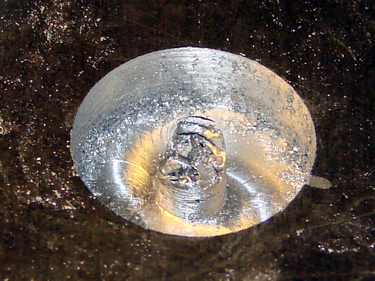
Of course, the stub broke off more or less flush with the bottom of the hole, so I continued milling downward to Z=-0.260, a bit more than halfway through the plate. This time, the needle-nose Vise-Grips got a good grip on an uncracked section and the remains twisted out with very little effort.
Grabbing the stub
Although the central pillar is outside the tap’s OD, leaving a solid aluminum shell, there’s not much meat to it. The shell broke off with the first twist and came out with the tap.
Those are not, by the way, gold-plated Vise-Grips. It’s a flash picture and the worklight is a warm-white compact fluorescent: the color correction that makes the aluminum look neutral gray turns the reflected CFL into gold.
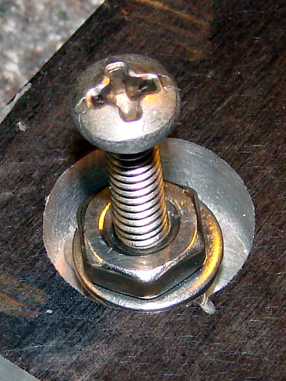
Aligning replacement nuts
I milled off the remains of the shell around the tapped hole, leaving a more-or-less flat bottom. If I cared enough, I’d machine a snug-fitting replacement aluminum plug, epoxy it into place, then (attempt to) drill-and-tap the hole again.
Instead, because the hole was deep enough for a pair of 6-32 nuts and a washer, I simply aligned those on a screw and filled the hole with JB Weld epoxy.
It doesn’t show in the picture, but the screw is well-lubricated with silicone grease to prevent it from becoming one with the nuts.
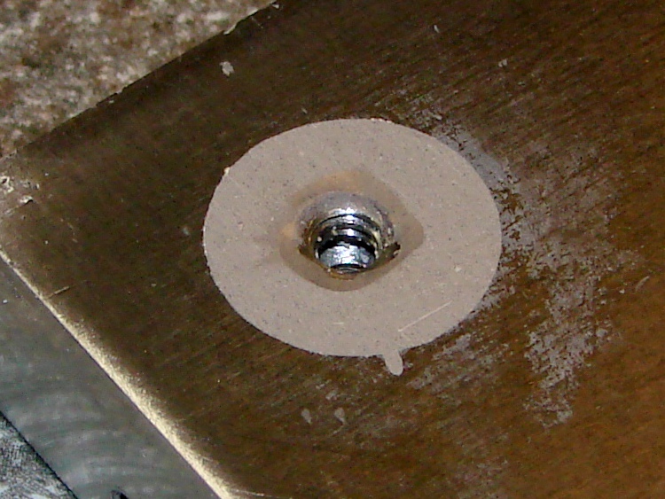
I eased epoxy into the recess, chasing out the inevitable air bubbles, and then scraped off most of the excess.
Epoxy fill
Let it cure overnight, scrub it on some sandpaper atop the sacrificial side of the surface plate, and it’s all good again…
Sanded flat
The little finger of epoxy sticking out to the front fills the end of the slit I carved into the top of the tap, which is visible in the other pictures if you look closely. The area around the hole isn’t stained; that’s smooth epoxy.
Of course, the thermal conductivity of epoxy is a lot less than that of solid aluminum. I’m not really pushing the limits of TO-220 packages, so this kludge will work fine in this application. It’s also nice that the repair is on the bottom of the heat spreader, where nobody will ever know I screwed up…
Now, to return to the project at hand, with even more motivation to avoid tapping holes in the future!
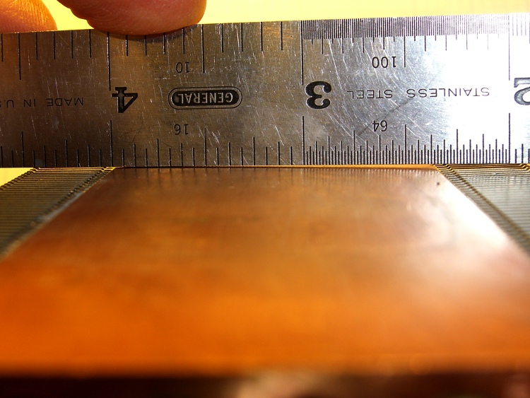
I suppose I should have known better: the bottom of that heatsink wasn’t anywhere near flat. I think it mated directly with the top of the CPU through thermal grease, not a compliant pad.
Curved copper heatsink surface
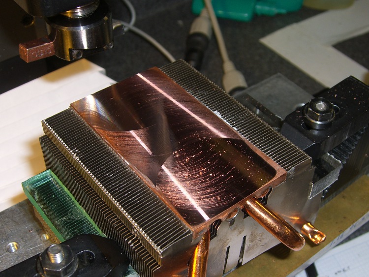
The obvious solution is to flycut the thing, which is where the Sherline’s limited Y-axis travel and teeny table put a cramp on your style. Normally, you’d put the length of the heatsink parallel to the X axis so the flycutter would clear on both ends, but there’s no obvious (read: quick and easy) way to clamp the thing that way.
So I mounted it parallel to the Y axis, which meant I couldn’t get the flycutter completely off the near end. The first pass at Z=-0.1 mm, however, showed that not only was the surface curved, but it wasn’t parallel to the top of the fins (which were flat on the tooling plate). I suppose I should have expected that.
This cut is has Z=-0.1 mm referred to the front end. It completely missed the other end:
First flycut pass
I flipped the heatsink around, measured the front-to-back tilt (about 0.16 mm), stuck a couple of brass shims under the front, and the second pass at Z=-0.05 mm from the new low point did the trick. Copper is nasty stuff and I did these cuts dry: the chips visible near the front are stuck firmly to the surface.
Final flycut pass
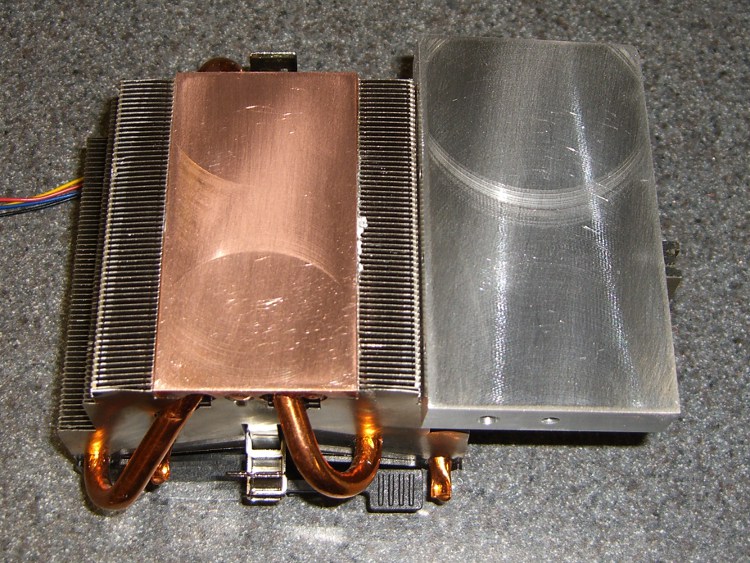
I scrubbed both the heatsink and the spreader plate on some fine sandpaper atop the sacrificial side of my surface plate until they were all good. I can see the remaining flycutter marks, but I can’t feel them, and the plates slap solidly together with a pffff of escaping air:
Flattened heatsink and spreader
A dab of heatsink compound should work wonders; the maximum dissipation will be under 20 W, roughly comparable to that old K6 CPU, but now the heatsink will be contacting the entire hot surface.