The CNC-3018XL fit into its new home with the Run/Hold buttons toward the front:
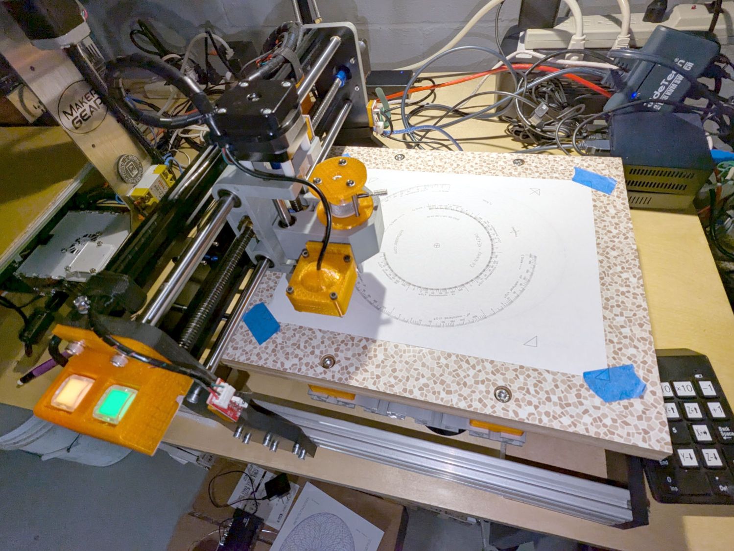
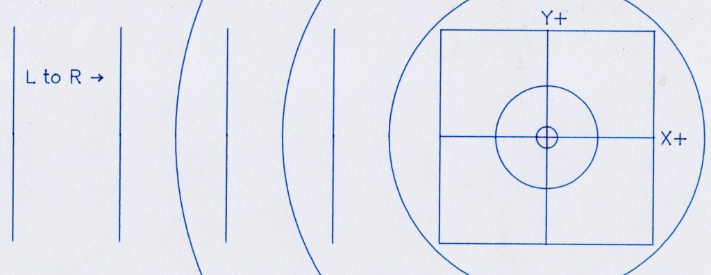
Which is rotated 180° from its previous orientation, putting Quadrant I and the most-positive coordinates in the left-front corner. Rather than stand on my head while trying to use the jog keypad upside-down, I reversed the axis directions by changing the GRBL Direction port invert mask value from its previous 4:
$3=7
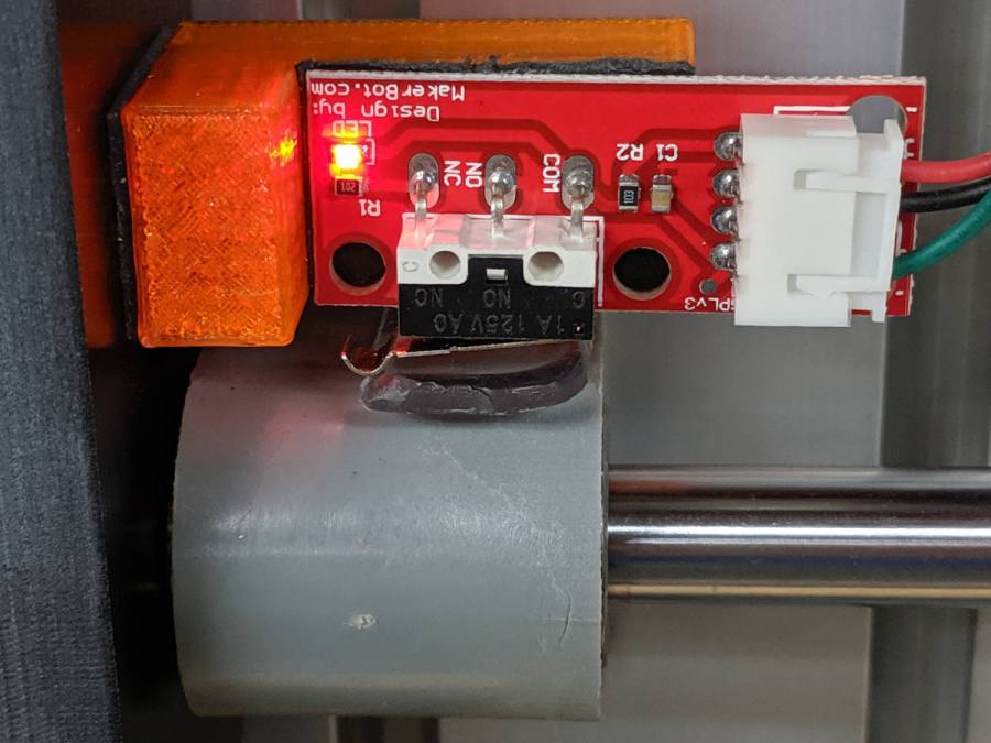
Because the home switch positions haven’t changed, reverse the Homing dir invert mask from 0:
$23=3
The XY origin remains in the center of the platform, so the G54 XY offset didn’t change. The Z offset puts the Pilot pen tip 10 mm above the platform, which will change as you (well, I) touch it off on the paper:
G10 L2 P1 X-169.0 Y-149.5 Z-44.0
Jog to the left rear corner (with Z at the home position) and set the G28 park position:
G28.1
Jog to the right front corner (also Z homed) where (manual) tool changes take place:
G30.1
Configure bCNC for manual tool changes without probing at the G30 position:
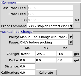
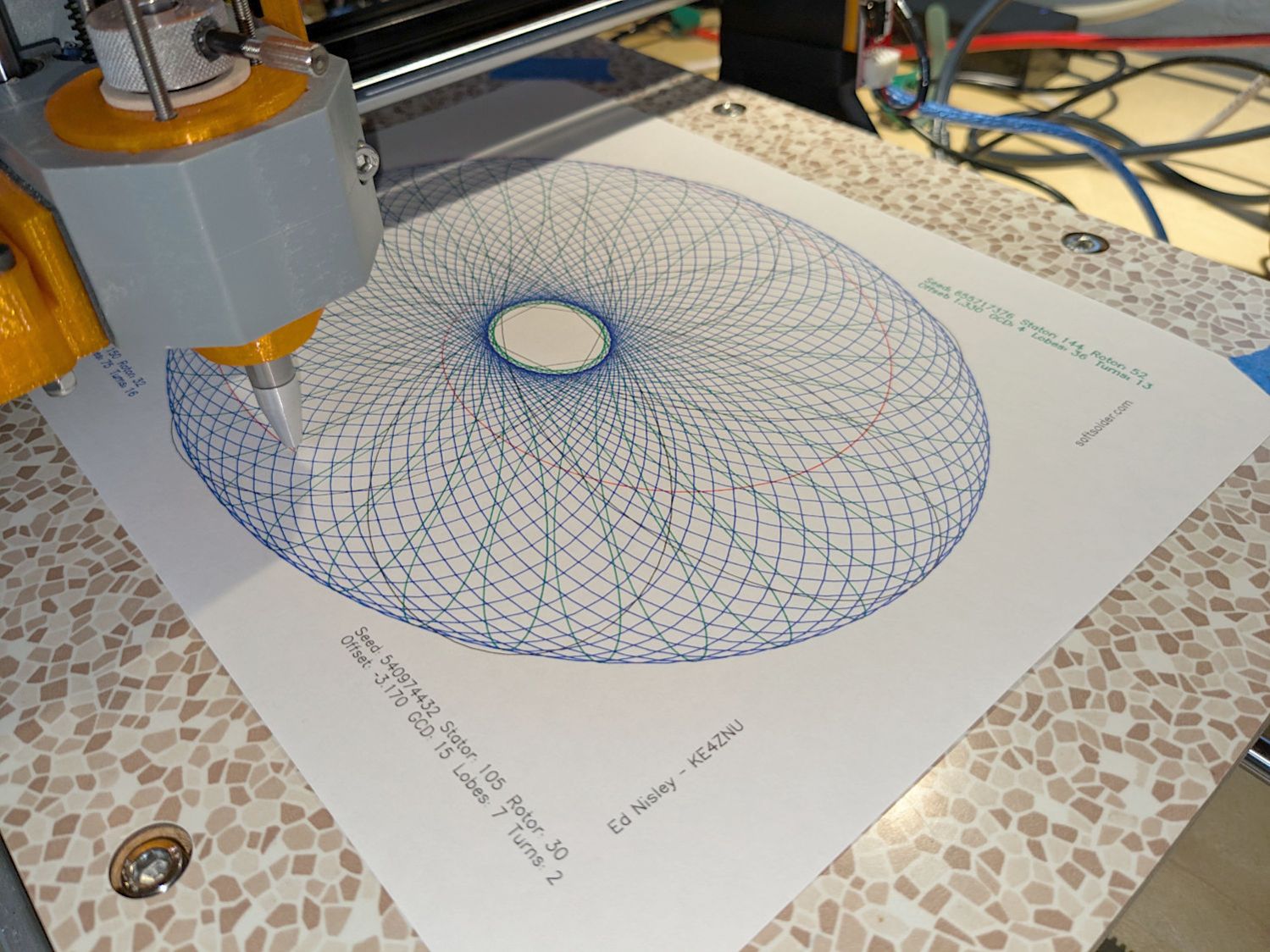
The machine will move to the tool change position at each Tn M6, the operator (that would be me) inserts tool pen n as needed, pokes the Run button, and watches it draw pretty pictures in a resolutely techie manner:
For completeness, the current GRBL settings:
$$
$0=10
$1=100
$2=0
$3=7
$4=0
$5=0
$6=0
$10=1
$11=0.010
$12=0.020
$13=0
$20=1
$21=0
$22=1
$23=3
$24=100.000
$25=2000.000
$26=25
$27=1.250
$30=1000
$31=0
$32=0
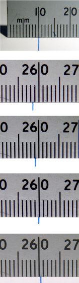
$100=401.284
$101=400.000
$102=400.000
$110=3000.000
$111=3000.000
$112=3000.000
$120=1000.000
$121=1000.000
$122=1000.000
$130=338.000
$131=299.000
$132=44.000
$#
[G54:-169.000,-149.500,-34.450]
[G55:0.000,0.000,0.000]
[G56:0.000,0.000,0.000]
[G57:0.000,0.000,0.000]
[G58:0.000,0.000,0.000]
[G59:0.000,0.000,0.000]
[G28:-335.000,-3.310,-3.450]
[G30:-1.000,-297.000,-1.000]
[G92:0.000,0.000,0.000]
[TLO:0.000]
[PRB:0.000,0.000,0.000:0]
The weird $100 X axis step/mm value is correct, because QC escapes are a thing.