Ed Nisley's Blog: Shop notes, electronics, firmware, machinery, 3D printing, laser cuttery, and curiosities. Contents: 100% human thinking, 0% AI slop.
With fifteen Guilloche swirly patterns imported and snapped into the template and the template aligned to the fixture, Fire The Laser:
Laser-engraved CD fixture – legend
The whole process takes a bit under 25 minutes:
Laser-engraved CD fixture – complete
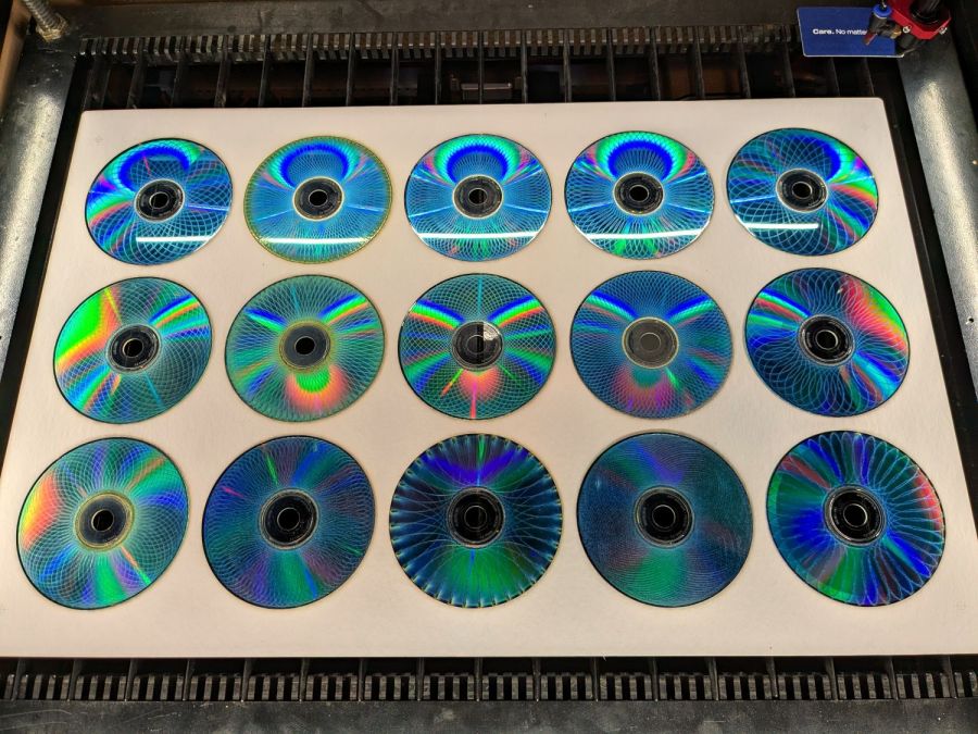
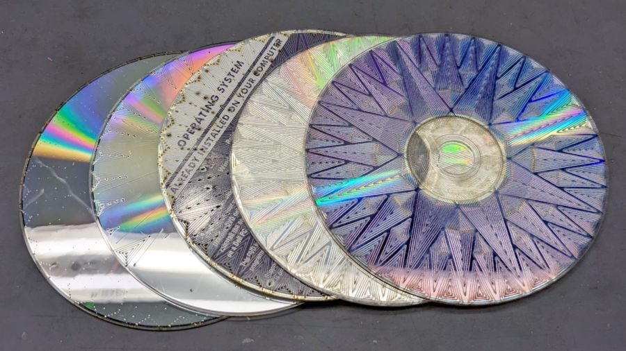
Which produces a stack of glittery proto-coasters:
Laser-engraved CD fixture – results
Although they’re all pretty-like, turning them into Real Coasters requires a cork base, MDF in the middle, wood glue, and adhesive sheets, all of which seems entirely too much like work.
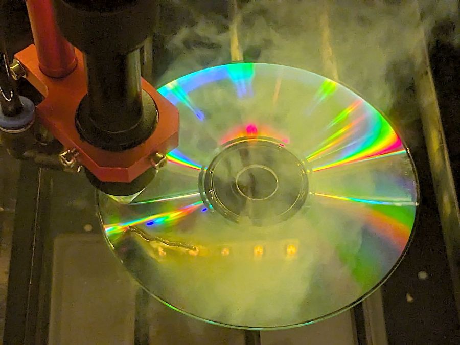
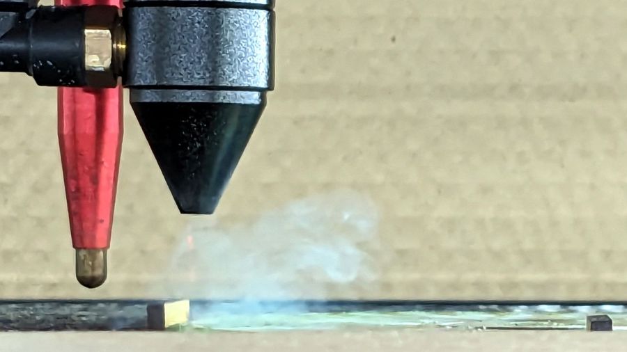
Just to see what happens, I tried cutting a shape from a scrap CD-R:
Laser cut CD – in progress
Cutting polycarbonate is a terrible idea, because that cloud consists primarily of The Big Stink™. AFAICT, the cutting fumes are not much more toxic than what burns off acrylic / wood / whatever, but they definitely smell much worse.
In any event, the laser produces a clean cut:
Laser cut CD – on platform
Modulo the charred edges and discoloration:
Laser cut CD – finished
Some of that buffs right out, but overall it’s not worth the effort unless you really need tiny diffraction gratings.
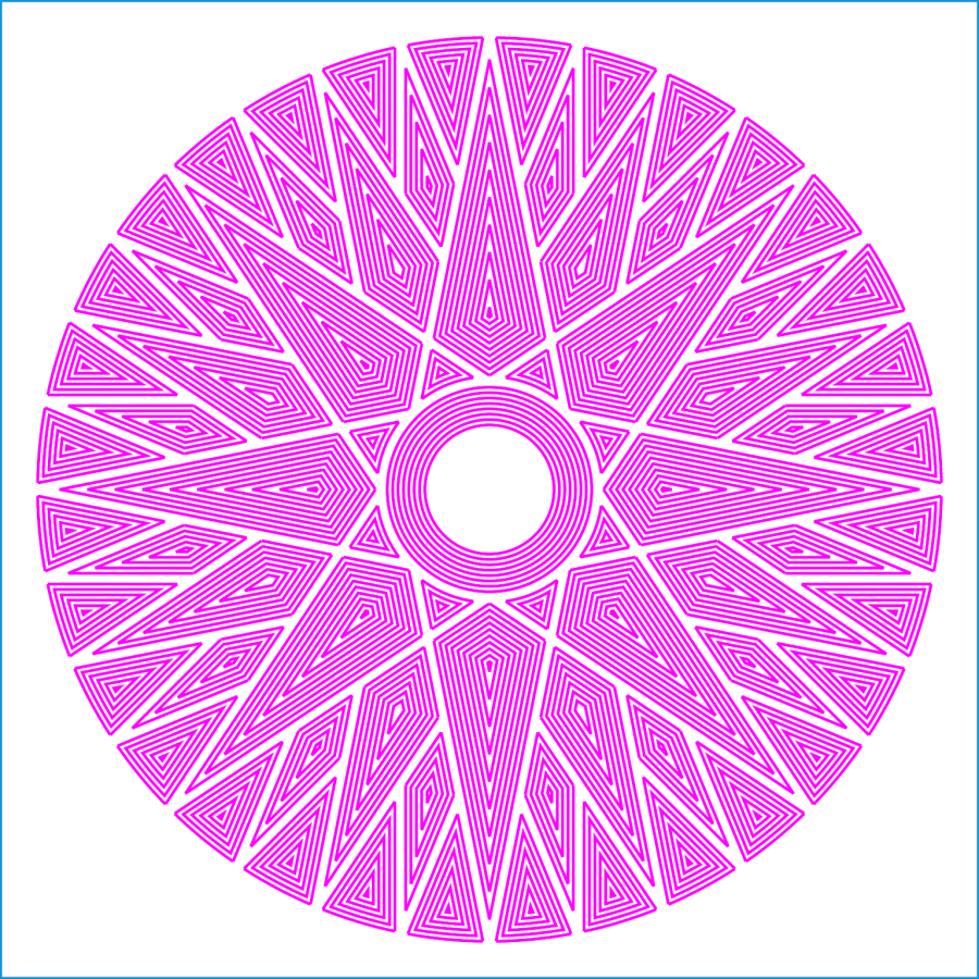
Wrecking scrap discs led to experimenting with the low-power behavior of my nominal 60 W CO₂ laser. I used the same inset version of the Mariner’s Compass quilting pattern as before:
Mariners Compass – stacked insets – LB layout
The KT332N controller is set to a 7% minimum power, as the tube simply doesn’t fire below that level. The power levels shown below are the minimum and maximum for the layer.
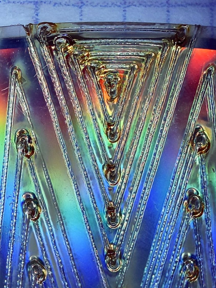
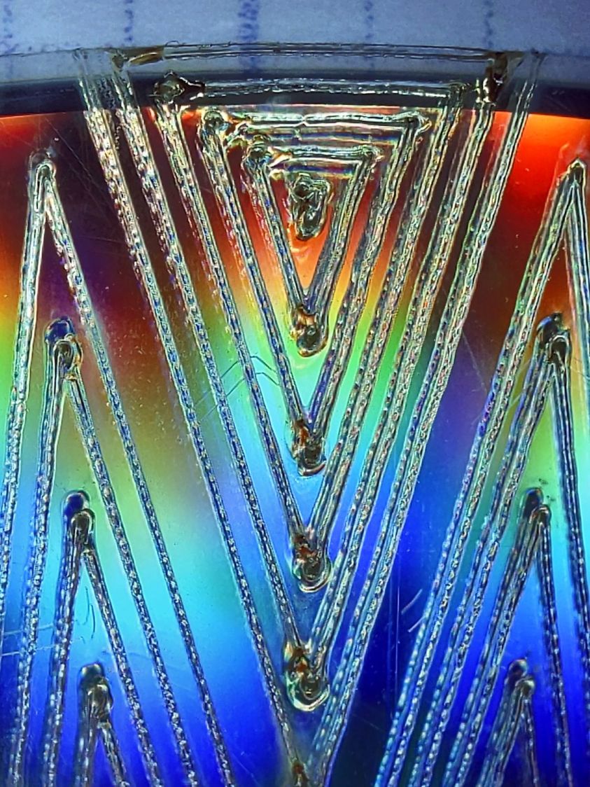
The cuts are on CD-R discs with the same general appearance, although I can’t say whether they all came from the same manufacturing lot. All of the cuts are on the clear side of the disc, with the data side flat against the platform. Unless otherwise noted, the pictures are from the clear side, looking down into the trenches carved into the surface, and you can see reflections of the cuts in the aluminized data layer.
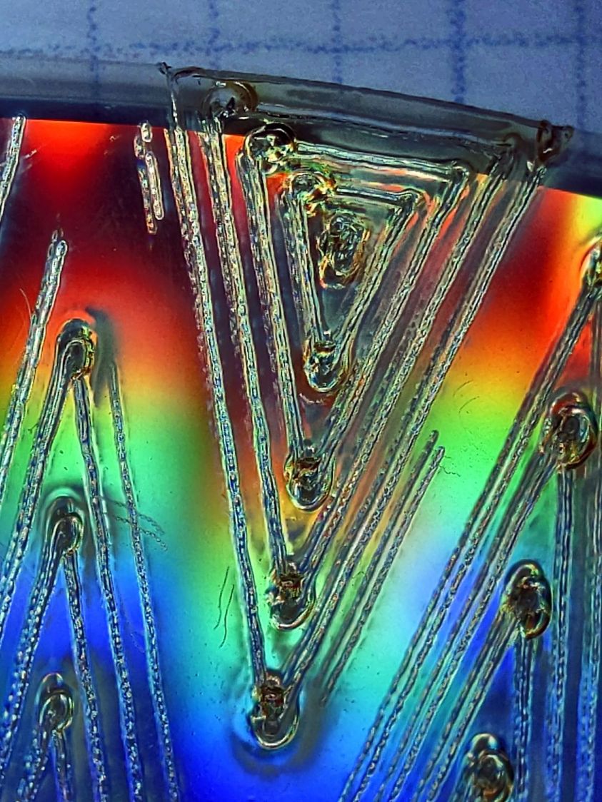
Power 7 to 10%:
CD-R vector cut – clear side – 7-10pct
Because the controller uses the minimum power at lower speeds, the laser fails to fire near the corners of the pattern.
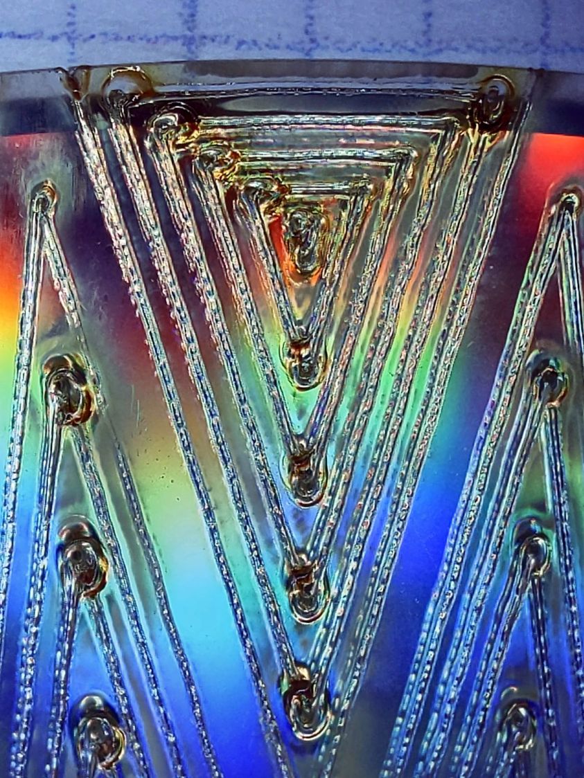
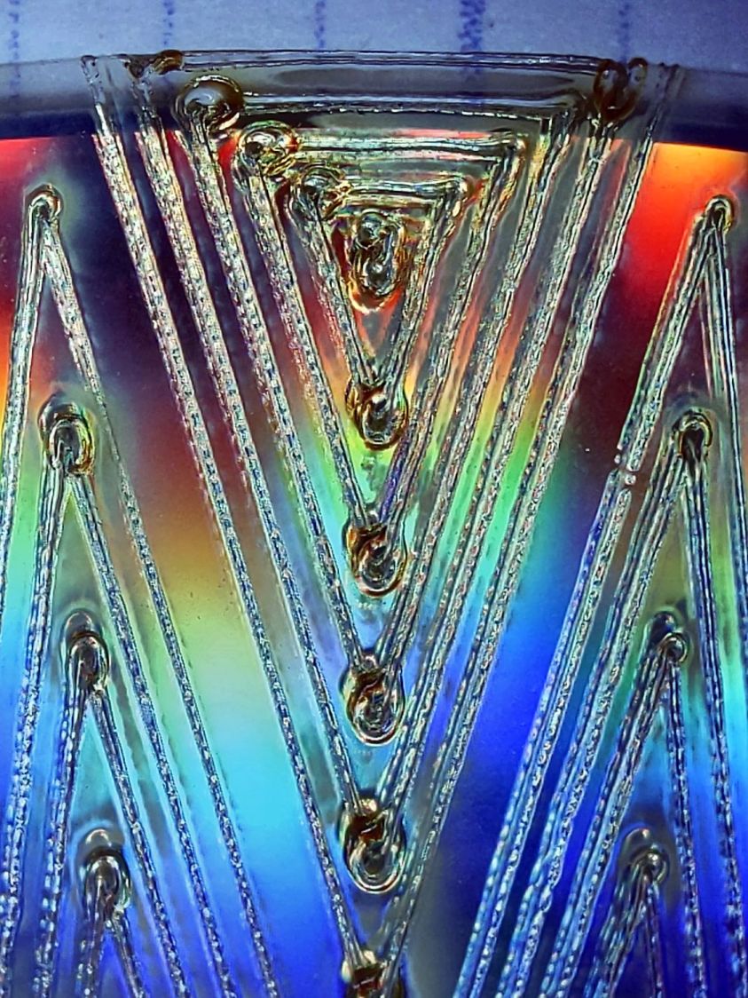
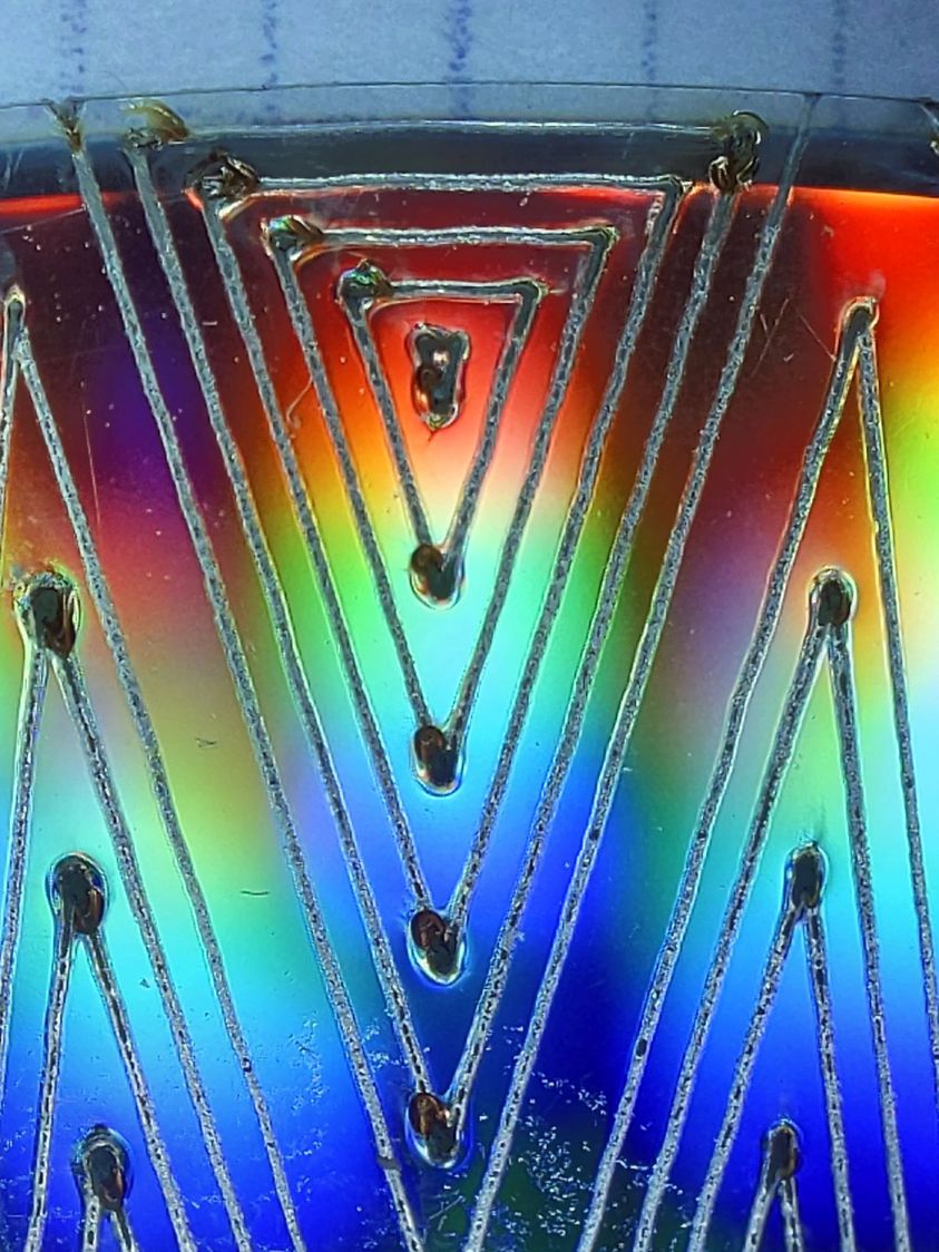
Power 8 to 10%:
CD-R vector cut – clear side – 8-10pct
The patterns generally begin in their upper-right corner where the laser has little enough power to prevent melting. However, the tube now continues firing as the laser slows for two other corners and melts a gouge into the surface.
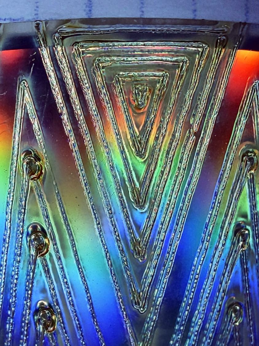
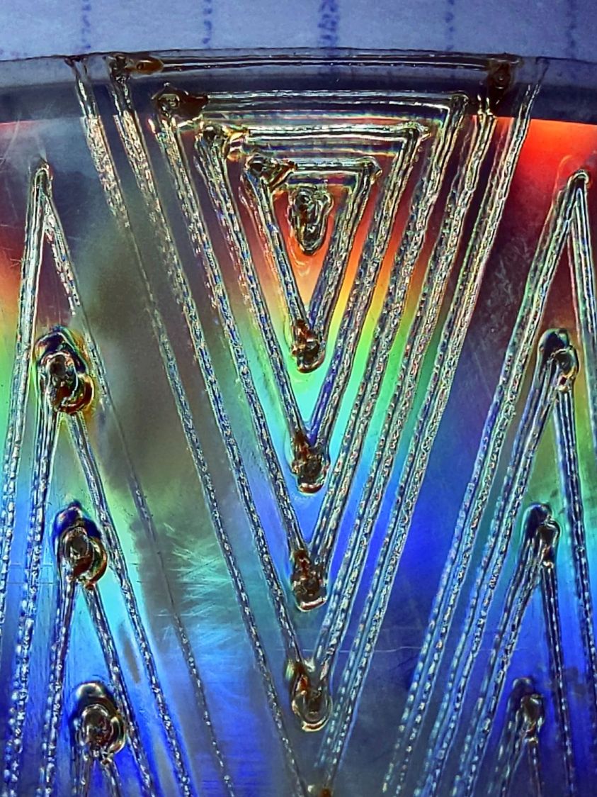
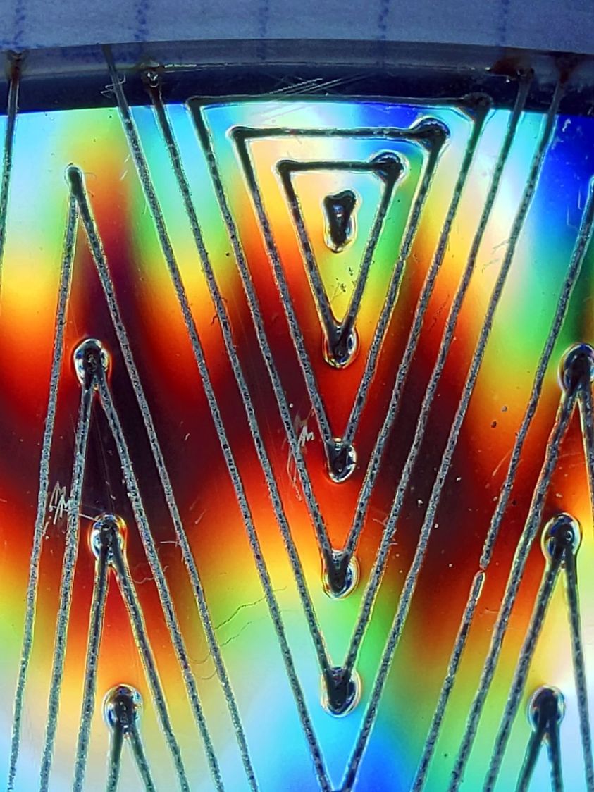
Power 7.5 to 10%:
CD-R vector cut – clear side – 7.5-10pct
The gouges are less prominent, but not by much.
Power 7.1 to 10%:
CD-R vector cut – clear side – 7.1-10pct
Reducing the minimum power to just over the 7% absolute minimum reduces the size of (most of) the blobs, but also causes gaps in some of the lines and at the corners.
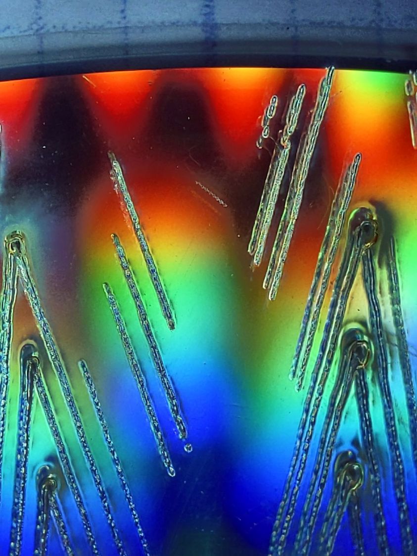
Power 7.1 to 7.5%:
CD-R vector cut – clear side – 7.1-7.5pct start
Reducing the maximum power causes the tube to not fire at all for some vectors; it doesn’t fire at all with the maximum power set to 7.1%.
However, the firing is very sensitive to the tube temperature, as that picture is for the first pattern around the disc rim with the cooling water temperature at 20.5 °C.
The last pattern (which is just to the right of the first) looks much better with the coolant at 20.7 °C:
CD-R vector cut – clear side – 7.1-7.5pct end
It’s still not complete, but you can see the tube power has increased enough to melt blobs into the surface similar to those at higher maximum powers.
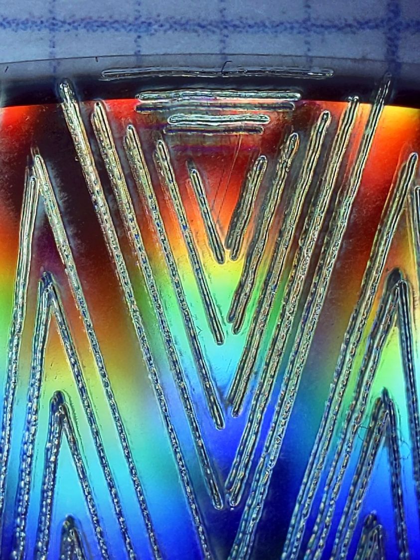
Power 7.5 to 8%:
CD-R vector cut – clear side – 7.5-8pct
Although the tube now fires continuously throughout the pattern, you can see thinner sections in the longer vectors over on the left.
All of the pictures above are using assist air at 12 l/min, so there’s a stiff breeze blowing the smoke away from the laser beam. Turning the assist air off reduces the flow to 2 l/min and produces a much larger cloud of fumes over the surface that seems to deposit more crud around the vectors:
CD-R vector cut – 2l-min assist air
The small MDF stops jammed in the honeycomb platform let me put all the CD-Rs at the same spot and reuse the same pattern with slight power variations and no realignment. It’s not perfect, but it’s pretty good.
CD-R vector cut – clear side – 7.5-8pct low air cleaned
If you’re being fussy about cleanliness, you might avoid scratching the otherwise pristine surface.
I also burned the data side of a disc to wreck the lacquer and aluminized layer, rather than just the clear polycarbonate.
Power 7.5 to 8% on data side, as seen from the data side:
CD-R vector cut – data side – 7.5-8pct data side
The same pattern on the same disc, seen from the clear side:
CD-R vector cut – data side – 7.5-8pct clear side
Burning through the lacquer and aluminum produces a narrower trench and slightly smaller blobs at the junctions.
Running near the tube’s minimum power produces unpredictable results, because the tube temperature matters. Variations of a few tenths of a degree can prevent the tube from firing, either intermittently or completely, so keeping the minimum layer power well above the minimum tube power is a Good Idea™ unless you can afford considerable scrap.
It’s a slow way to wreck discs, but a nice way to produce suncatching coasters:
Pretty much as expected, the cheap craft adhesive sheet turned out to be inadequate to the task of holding the thin upper border ring onto the clutter collector:
Layered Acrylic Desk Junk Collector – overview
So I stripped the adhesive off with naptha and arranged a cut in a 3M 300LSE acrylic adhesive sheet:
Desk clutter plate – 300LSE adhesive sheet
Four small tabs held that ring to the central piece while I stuck the acrylic ring on it, which turned out to be easy enough. Then I cut the tabs, peeled the paper off the other side, stuck the ring to the plate, and it’s once again ready for clutter.
The bond is visibly better when viewed through the top of the ring, so I think the 300LSE adhesive is thicker and gooier than the craft sheet adhesive, which isn’t surprising at all.
Scale it to 120 mm OD, delete the innermost circles under 15 mm diameter, then go wreck yourself some CDs and DVDs:
Mariners Compass Coaster – CD DVD tests
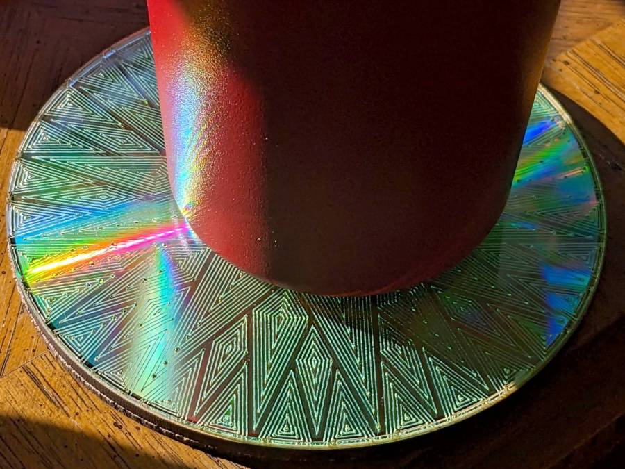
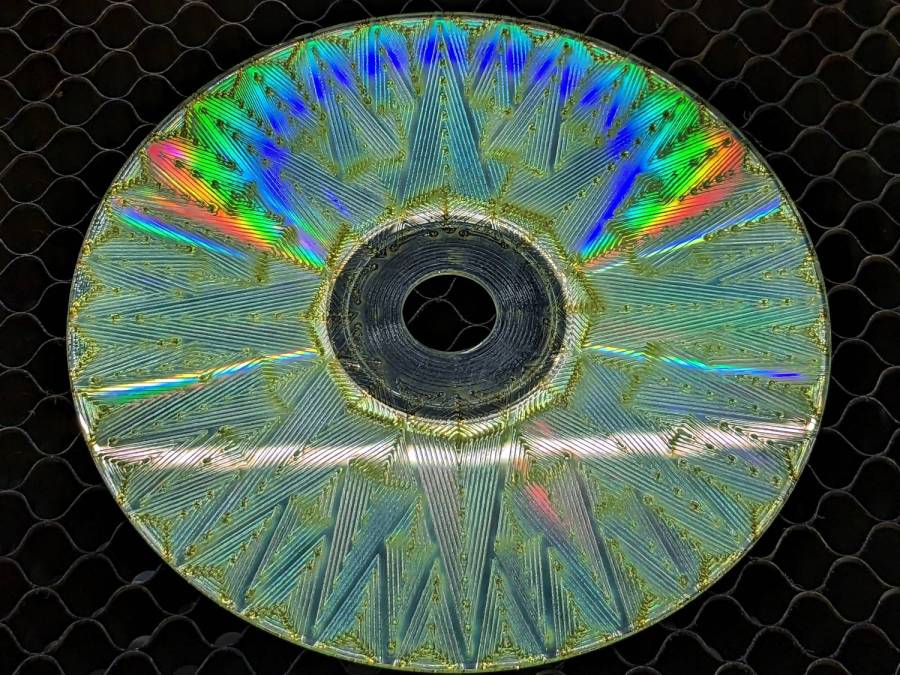
Those were test pieces to figure out speeds and powers starting from the polycarbonate settings used for the Guilloché DVD now serving as a coaster atop the laser.
When you’re looking to destroy the surface, then pretty doesn’t matter, but they come out surprisingly nice in a techie sort of way:
Mariners Compass Coaster – CD clear side test
That’s burned into the clear side of the CD before I figured out how to control the power at the starting points.
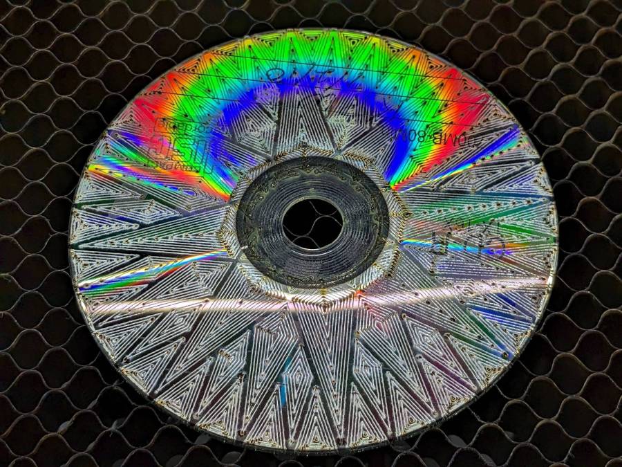
This CD-R came out a nice silver, with the tracks burned into the data / label side:
Mariners Compass Coaster – CD-R test
The polycarb tends to scorch & discolor at the starting point of each polygon, where the laser dwells momentarily after lighting up. Avoiding that requires setting the minimum layer power 1% below the Ruida controller’s minimum firing power. In this case, running the layer at 7% minimum with the controller set to fire at 8% completely eliminates the scorches.
The maximum power is about 10% for the clear side. The data side requires only 10% for lightly coated CD-R / CD-RW and maybe 25% for the heavily inked labels of pressed CDs (like the Dell reinstallation CD in the first picture). It helps to start with a vast supply of unwanted discs.
Suiting action to words:
Mariners Compass Coaster – CD data side finished
That’s a CD-R wrecked on the data side, stuck to an MDF disk with a cheap craft adhesive sheet and a cork disk wood-glued to the bottom. Carefully hidden here, the central hole sports a 15 mm chipboard disk contrasting horribly with the CD; it cannot be more than 1 mm thick to avoid having it stick up beyond the plastic surface and chipboard is what I have in that thickness.
The advantages of wrecking the data side:
Leaving the clear side smooth, so crud won’t accumulate / grow in the grooves
Absolutely, positively, utterly destroying the data track
The advantages of wrecking the clear side:
Maybe breaking the seal formed by condensation under the mug / glass / cup
Leaving the data side intact, so the coating won’t disintegrate and peel off the adhesive
In either case, however, I’m sure the data is gone.
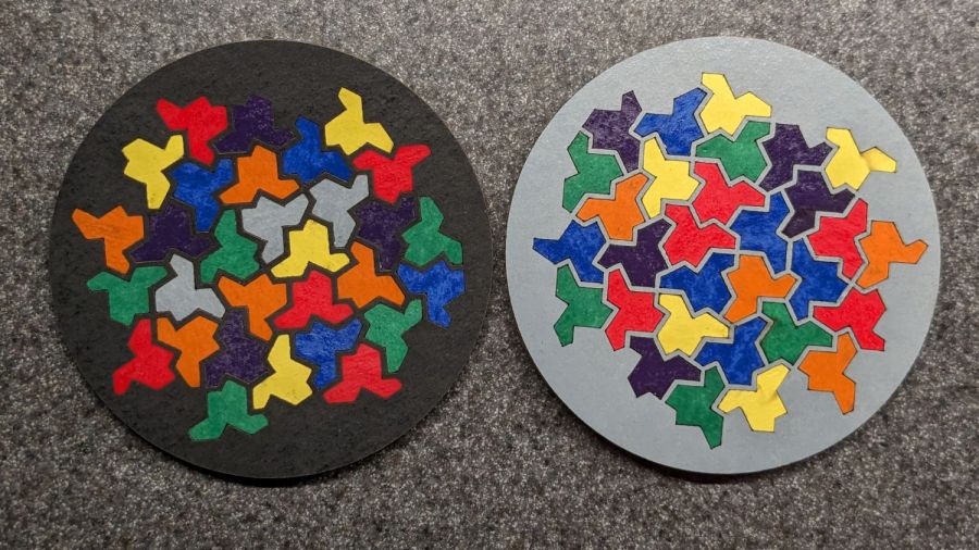
They’re rattlecan colored chipboard atop MDF atop cork, with the tiles cut from half a dozen sheets of einsteins. The lighter colors suffered from ineffective tape masking during cutting, producing more smudging than I’d like, but overall they look pretty good.
I was surprised at how dull the black surround turned out and how good the gray appears: rapid prototyping & iteration in full effect.
Unlike the layered paper version, these require a great deal of fiddly handwork.
I hope the MDF will prevent the premature warping afflicting the chipboard-on-cork coasters. Perhaps shooting the assembled coasters with a clearcoat would help, although you do want coasters to be a bit absorbent, lest they stick to wet cups / mugs / glasses in humid weather.
Go to the source and bring back a suitable number of tiled einsteins:
Einstein tiling
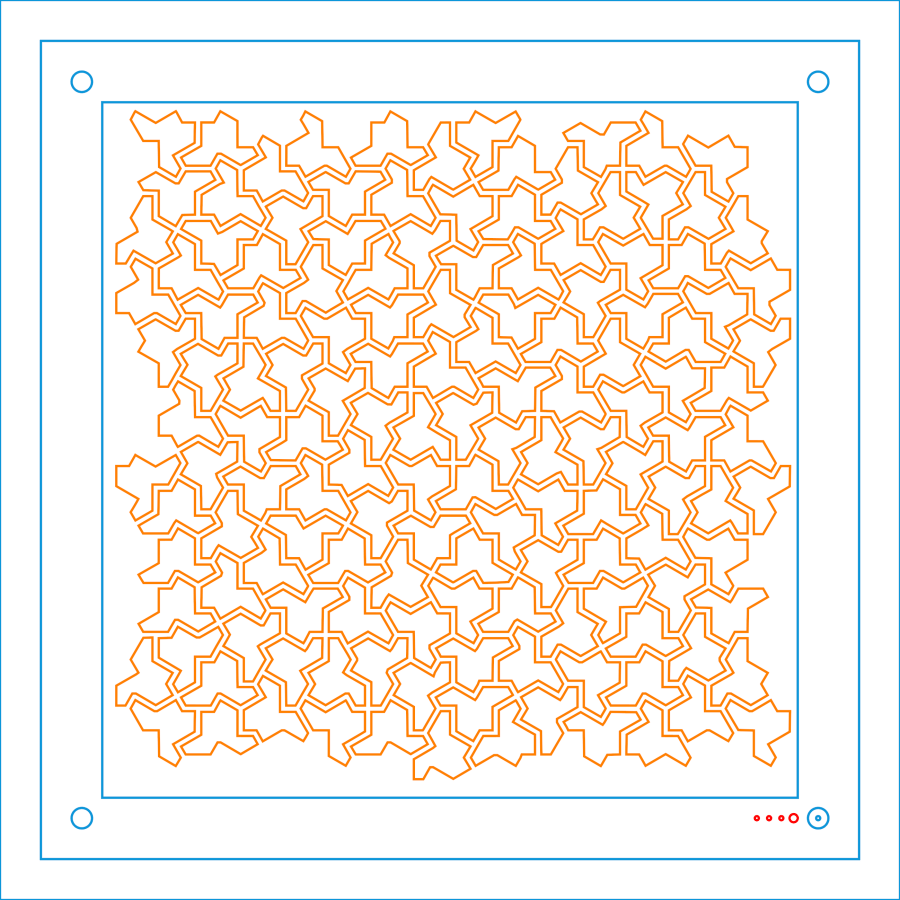
Import the bitmap into LightBurn, fiddle with the tracing until it lays down two lines along each border, apply a 1 mm inset to all the tiles, then scale & crop & delete to fit a 170 mm square:
Einsteins – LB paper – top layer
Cut one of those sheets, tape it to a sheet of white paper, fire up a calculator, generate a random number, write the first digit in the upper-left tile, and iterate to fill in all the tiles.
Duplicate that layout and delete all the tiles marked with a zero to get the next layer.
Iterate for all ten layers:
Einsteins – LB paper cuts
Set up the fixture, do the Print-and-Cut alignment, then cut all the layers with different colors:
Layered Paper cutting fixture – in use
Assemble the layers with some stick adhesive:
Layered Paper – Einsteins
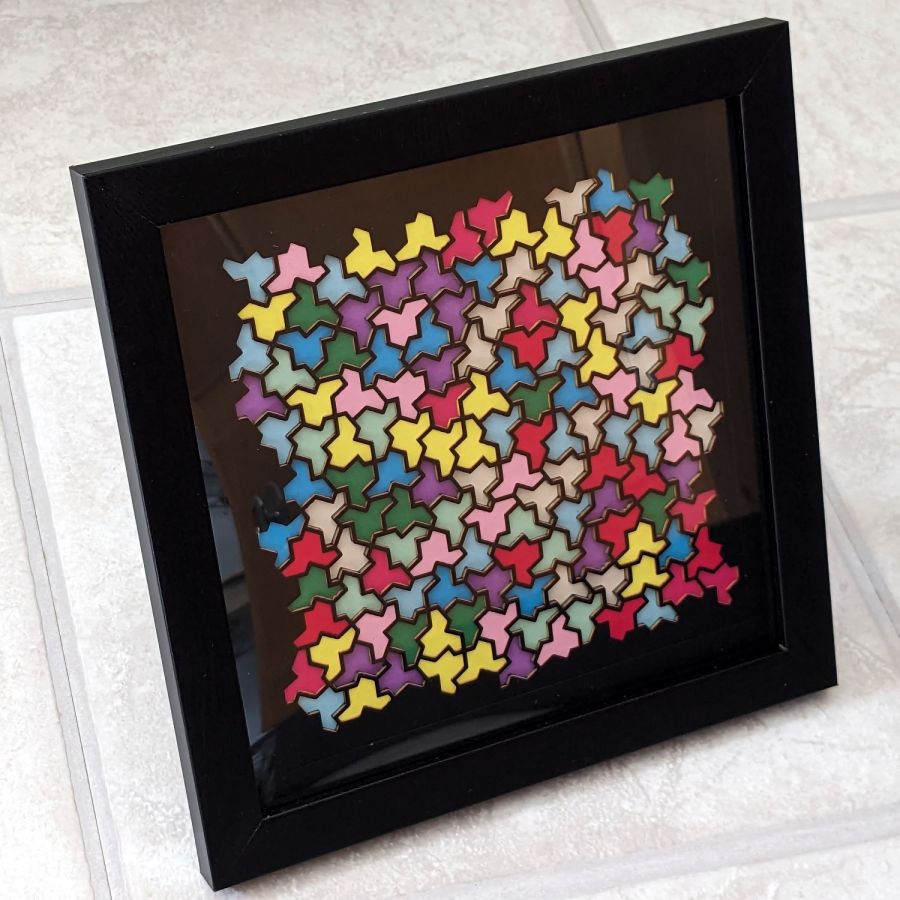
Frame it and admire:
Layered Paper – Einsteins
It’s way busier than the quilt blocks, but I like it.