
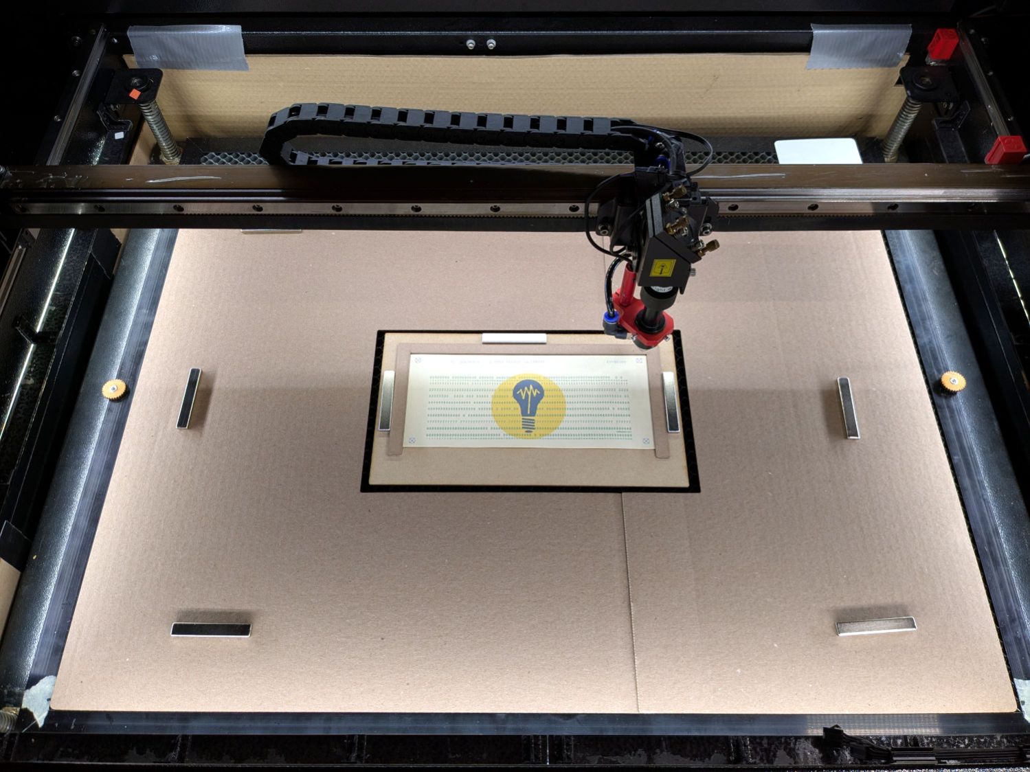
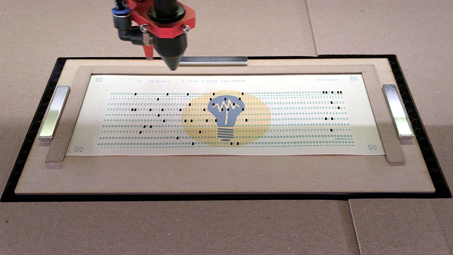
With a fixture aligning a printed card in the laser for cutting and trays for incoming and outgoing cards, it’s time to generate SVGs for printing and cutting. I use the svg.py library to translate card geometry into SVG elements.
For example, this draws a rectangle around the card perimeter with a color that will automagically put it on a LightBurn tool layer used for alignment:
if args.layout == "laser":
    ToolEls.append(
        svg.Rect(
            x=0,
            y=0,
            width=svg.mm(CardSize[X]),
            height=svg.mm(CardSize[Y]),
            stroke=Tooling,
            stroke_width=svg.mm(DefStroke),
            fill="none",
        )
    )
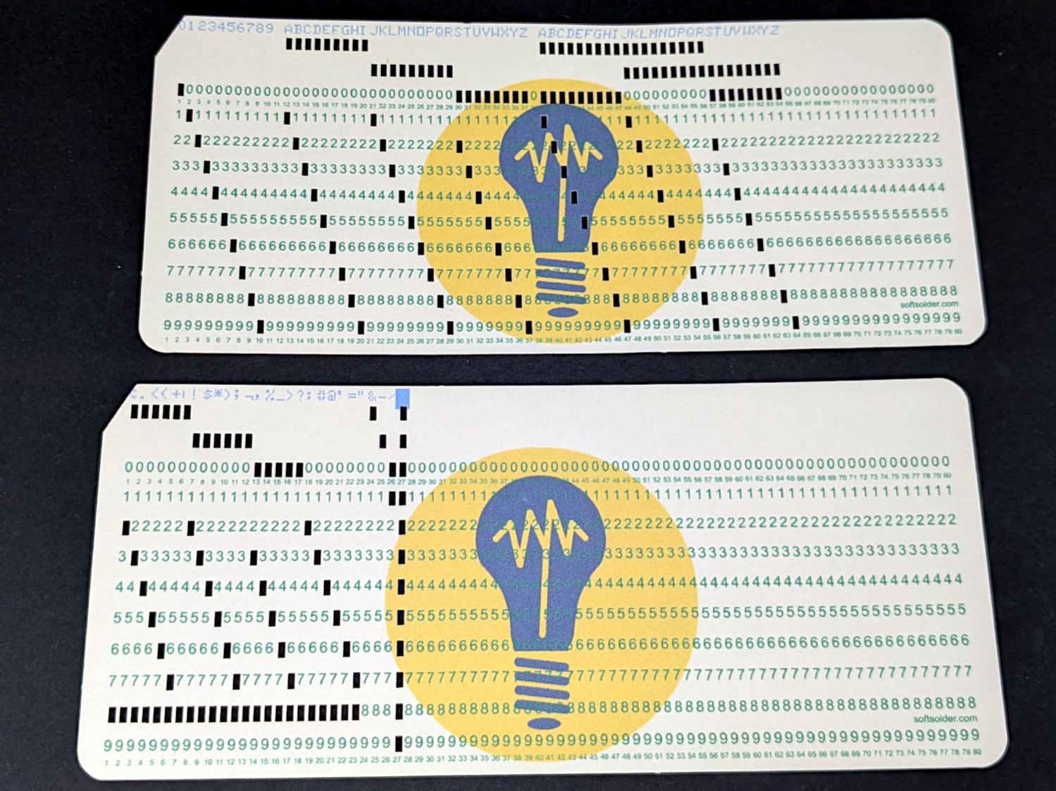
Because I know the exact size of the card layout, all the coordinates / sizes / widths will be in hard millimeters. The constant INCH converts from the hard inch sizes of the OG IBM card layout.
The args.layout variable corresponds to a command-line switch selecting output for either “print” or “laser”, because each requires different SVG elements and attributes. In this case, the card outline appears only in the laser file, because it should not be printed on the card face.
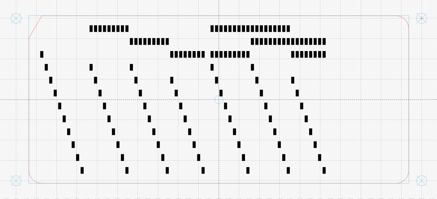
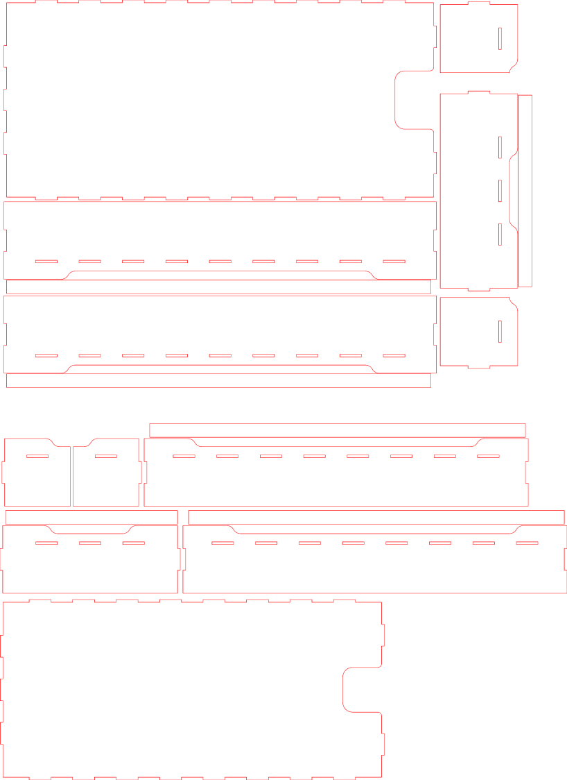
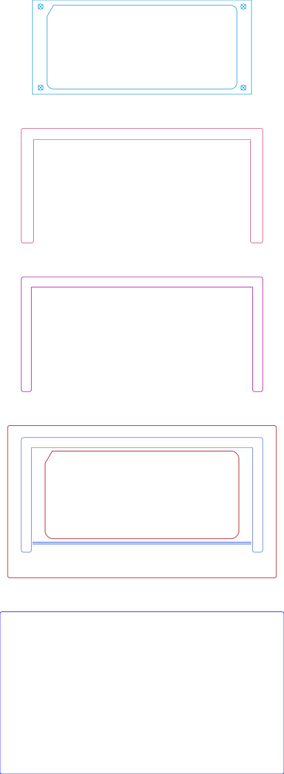
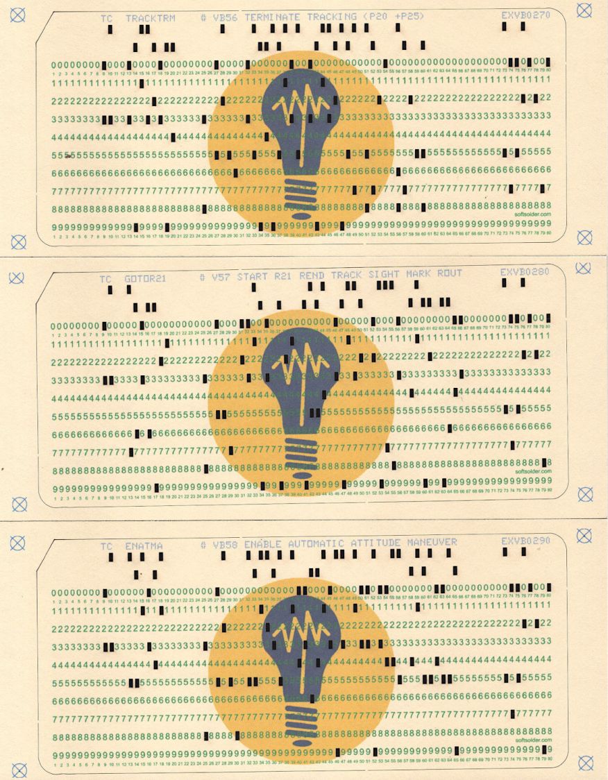
Eventually, the SVG for the laser will look like this, with the blue rectangle boxing its red perimeter:
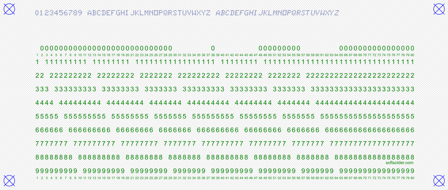
The corresponding SVG to be printed, without the rectangle:
Both SVGs have four alignment targets at exactly the same coordinates, although in different colors for their different purposes. The laser targets appear on a tool layer where they can be selected to position the laser head over the corresponding printed targets on the card in the fixture:
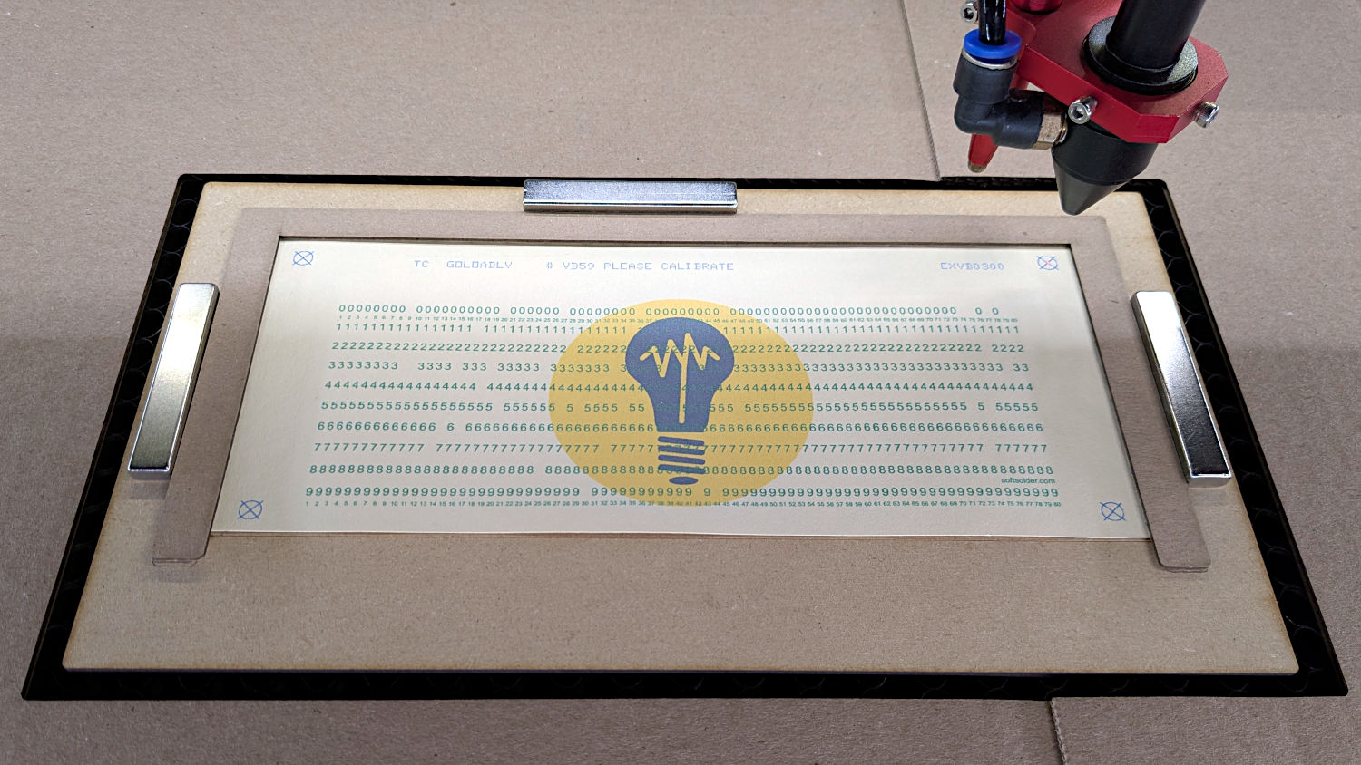
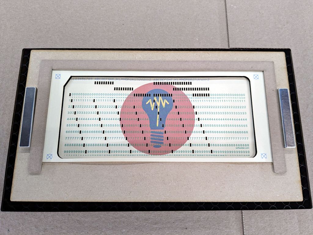
Subsequent steps in the process composite the fancy logo under the SVG layout and scale the result before printing the card.
This chunk of code produces those targets:
for c in ((1,1),(-1,1),(-1,-1),(1,-1)):
    ctr = (CardSize[X]/2 + c[X]*TargetOC[X]/2,CardSize[Y]/2 + c[Y]*TargetOC[Y]/2)
    MarkEls.append(
        svg.Circle(
            cx=svg.mm(ctr[X]),
            cy=svg.mm(ctr[Y]),
            r=svg.mm(TargetOD/2),
            stroke=Tooling if args.layout == "laser" else CardMark,
            stroke_width=svg.mm(DefStroke),
            fill="none",
        )
    )
    MarkEls.append(
        svg.Path(
            d=[
                svg.M(ctr[X] + TargetOD/2,ctr[Y] - TargetOD/2),
                svg.l(-TargetOD,TargetOD),
                svg.m(0,-TargetOD),
                svg.l(TargetOD,TargetOD),
            ],
            transform="scale(" + repr(1.0 if args.lbsvg else SVGSCALE) + ")",
            stroke=Tooling if args.layout == "laser" else CardMark,
            stroke_width=svg.mm(DefStroke if args.lbsvg else DefStroke/SVGSCALE),
            fill="none",
        )
    )
The stroke attribute sets the color of the result, with the Python ternary operator picking the appropriate RGB value based on args.layout.
The args.lbsvg variable comes into play when the LightBurn interpretation of an SVG attribute or element differs from the Inkscape interpretation. I have absolutely no idea what’s going on in those situations, other than that the two programs sometimes regard coordinates / distances differently.
For example, LightBurn regards the “user units” in a Path as millimeters and Inkscape regards them as “SVG pixels” requiring a scale factor I defined as SVGSCALE = 96.0/25.4 to get the right size. If there’s a less awful way to match them, I’m all eyes.
Although setting args.layout to “laser” and args.lbsvg to True generally makes sense, I may want to print the “laser” layout for cross-checking. Hilarity generally ensues until I remember args.lbsvg. It’s worth noting the code has zero error checking, so hilarity generally continues until I fix whatever got missed.
With that in mind, this Path traces the card perimeter:
if args.layout == "laser":
    CardEls.append(
        svg.Path(
            d=[
                svg.M(0.25*INCH,0),
                svg.h(CardSize[X] - 2*0.25*INCH),
                svg.a(0.250*INCH,0.25*INCH,0,0,1,0.25*INCH,0.25*INCH),
                svg.v(CardSize[Y] - 2*0.25*INCH),
                svg.a(0.25*INCH,0.25*INCH,0,0,1,-0.25*INCH,0.25*INCH),
                svg.H(0.25*INCH),
                svg.a(0.25*INCH,0.25*INCH,0,0,1,-0.25*INCH,-0.25*INCH),
                svg.V(0.25*INCH/math.tan(math.radians(30))),
                svg.Z(),
            ],
            transform="scale(" + repr(1.0 if args.lbsvg else SVGSCALE) + ")",
            stroke=CardCut if args.layout == "laser" else Tooling,
            stroke_width=svg.mm(DefStroke if args.lbsvg else DefStroke/SVGSCALE),
            fill="none",
        ),
    )
Note that the stroke_width attribute also requires scaling, lest it take on a broad-brush aspect.
More on generating the various characters and punching the holes to come …
The Python source code as a GitHub Gist:
| # Generator for punched cards | |
| # Ed Nisley – KE4ZNU | |
| # 2026-01-20 cargo-culted from various sources | |
| import svg | |
| import math | |
| from argparse import ArgumentParser | |
| from pathlib import Path | |
| import curses.ascii | |
| import itertools | |
| INCH = 25.4 | |
| X = 0 | |
| Y = 1 | |
| SVGSCALE = 96.0/25.4 # converts "millimeters as SVG points" to real millimeters | |
| parser = ArgumentParser(description="Create SVG files to print & laser-cut a punched card") | |
| parser.add_argument('–debug',action='store_true', | |
| help="Enable various test outputs, do not use XML file") | |
| parser.add_argument('–lower',action='store_true', | |
| help="Fake lowercase with italics") | |
| parser.add_argument('–test', type=int, choices=range(7), default=0, | |
| help="Various test patterns to verify card generation") | |
| parser.add_argument('–lbsvg', action='store_true', | |
| help="Work around LightBurn SVG issues") | |
| parser.add_argument('–layout', default="print", choices=["laser","print"], | |
| help="Laser-engrave hole & char text into card") | |
| parser.add_argument('–seq',type=int, default=0, | |
| help="If nonzero, use as squence number in col 72-80") | |
| parser.add_argument('–logofile', default="Card logo.png", | |
| help="Card logo filename") | |
| parser.add_argument('–prefix', default="", | |
| help="Card number prefix, no more than 5 characters") | |
| parser.add_argument('contents',nargs="*",default='Your text goes here', | |
| help="Line of text to be punched on card") | |
| args = parser.parse_args() | |
| PageSize = (round(8.5*INCH,3), round(11.0*INCH,3)) # sheet of paper | |
| CardSize = (7.375*INCH,3.25*INCH) # punch card bounding box | |
| NumCols = 80 | |
| NumRows = 12 | |
| HoleSize = (0.055*INCH,0.125*INCH) # punched hole | |
| HoleOC = (0.087*INCH,0.250*INCH) | |
| BaseHoleAt = (0.251*INCH,0.250*INCH) # center point | |
| TargetOC = (200,80) # alignment targets around card | |
| TargetOD = 5 | |
| #— map ASCII / Unicode characters to rows | |
| # rows are names, not indexes: Row 12 is along the top of the card | |
| # Row 10 is the same as Row 0 | |
| CharMap = { | |
| " ": (), | |
| "0": (0,), | |
| "1": (1,), | |
| "2": (2,), | |
| "3": (3,), | |
| "4": (4,), | |
| "5": (5,), | |
| "6": (6,), | |
| "7": (7,), | |
| "8": (8,), | |
| "9": (9,), | |
| "A": (12,1), | |
| "B": (12,2), | |
| "C": (12,3), | |
| "D": (12,4), | |
| "E": (12,5), | |
| "F": (12,6), | |
| "G": (12,7), | |
| "H": (12,8), | |
| "I": (12,9), | |
| "J": (11,1), | |
| "K": (11,2), | |
| "L": (11,3), | |
| "M": (11,4), | |
| "N": (11,5), | |
| "O": (11,6), | |
| "P": (11,7), | |
| "Q": (11,8), | |
| "R": (11,9), | |
| "S": (10,2), | |
| "T": (10,3), | |
| "U": (10,4), | |
| "V": (10,5), | |
| "W": (10,6), | |
| "X": (10,7), | |
| "Y": (10,8), | |
| "Z": (10,9), | |
| "a": (12,10,1), | |
| "b": (12,10,2), | |
| "c": (12,10,3), | |
| "d": (12,10,4), | |
| "e": (12,10,5), | |
| "f": (12,10,6), | |
| "g": (12,10,7), | |
| "h": (12,10,8), | |
| "i": (12,10,9), | |
| "j": (12,11,1), | |
| "k": (12,11,2), | |
| "l": (12,11,3), | |
| "m": (12,11,4), | |
| "n": (12,11,5), | |
| "o": (12,11,6), | |
| "p": (12,11,7), | |
| "q": (12,11,8), | |
| "r": (12,11,9), | |
| "s": (10,11,2), | |
| "t": (10,11,3), | |
| "u": (10,11,4), | |
| "v": (10,11,5), | |
| "w": (10,11,6), | |
| "x": (10,11,7), | |
| "y": (10,11,8), | |
| "z": (10,11,9), | |
| "¢": (12,2,8), | |
| ".": (12,3,8), | |
| "<": (12,4,8), | |
| "(": (12,5,8), | |
| "+": (12,6,8), | |
| "|": (12,7,8), | |
| "!": (11,2,8), | |
| "$": (11,3,8), | |
| "*": (11,4,8), | |
| ")": (11,5,8), | |
| ";": (11,6,8), | |
| "¬": (11,7,8), | |
| ",": (10,3,8), | |
| "%": (10,4,8), | |
| "_": (10,5,8), | |
| ">": (10,6,8), | |
| "?": (10,7,8), | |
| ":": (2,8), | |
| "#": (3,8), | |
| "@": (4,8), | |
| "'": (5,8), | |
| "=": (6,8), | |
| '"': (7,8), | |
| "&": (12,), | |
| "-": (11,), | |
| "/": (10,1), | |
| "█": (12,11,10,1,2,3,4,5,6,7,8,9), # used for lace card test pattern | |
| "▯": (12,10,2,4,6,8), # used for alignment tests with hack for row numbers | |
| } | |
| #— map row name to physical row offset from top | |
| RowMap = (2,3,4,5,6,7,8,9,10,11,2,1,0) | |
| RowGlyphs = "0123456789⁰¹²▯" # last four should never appear, hollow box is a hack | |
| #— pretty punch patterns | |
| TestStrings = ( " " * NumCols, # blank card for printing | |
| "█" * NumCols, # lace card for amusement | |
| "0123456789 ABCDEFGHIJKLMNOPQRSTUVWXYZ abcdefghijklmnopqrstuvwxyz", | |
| "¢.<(+|!$*);¬,%_>?:#@'=" + '"' + "&-/█", | |
| "▯" * NumCols, # hack for row number alignment | |
| ) | |
| #— LightBurn layer colors | |
| HoleCut = "black" # C00 Black | |
| CardMark = "blue" # C01 Blue | |
| CardCut = "red" # C02 Red | |
| CardText = "green" # C03 Green | |
| CardGray = "rgb(125,135,185)" # C17 Dark Gray | |
| Tooling = "rgb(12,150,217)" # T2 Tool | |
| #— LightBurn uses only the stroke | |
| DefStroke = 0.20 | |
| DefFill = "none" | |
| #——————— | |
| # Set up card contents | |
| if args.test: # test patterns used without changes | |
| Contents = TestStrings[args.test – 1].ljust(NumCols,' ') | |
| else: # real cards need cleaning | |
| Contents = ''.join(itertools.chain(*args.contents)) | |
| if args.seq: | |
| nl = 8 – len(args.prefix) | |
| Contents = Contents.ljust(NumCols – 8,' ')[:(NumCols – 8)] | |
| Contents = Contents + f"{args.prefix}{args.seq:0{nl}d}" | |
| else: | |
| Contents = Contents.ljust(NumCols,' ')[:NumCols] | |
| if not args.lower: | |
| Contents = Contents.upper() | |
| #— accumulate tooling layout | |
| ToolEls = [] | |
| # mark center of card for drag-n-drop location | |
| if args.layout == "laser": | |
| ToolEls.append( | |
| svg.Circle( | |
| cx=svg.mm(CardSize[X]/2), | |
| cy=svg.mm(CardSize[Y]/2), | |
| r="2mm", | |
| stroke=Tooling, | |
| stroke_width=svg.mm(DefStroke), | |
| fill="none", | |
| ) | |
| ) | |
| # mark card perimeter for alignment check | |
| if args.layout == "laser": | |
| ToolEls.append( | |
| svg.Rect( | |
| x=0, | |
| y=0, | |
| width=svg.mm(CardSize[X]), | |
| height=svg.mm(CardSize[Y]), | |
| stroke=Tooling, | |
| stroke_width=svg.mm(DefStroke), | |
| fill="none", | |
| ) | |
| ) | |
| #— accumulate alignment targets | |
| MarkEls = [] | |
| # alignment targets | |
| for c in ((1,1),(-1,1),(-1,-1),(1,-1)): | |
| ctr = (CardSize[X]/2 + c[X]*TargetOC[X]/2,CardSize[Y]/2 + c[Y]*TargetOC[Y]/2) | |
| MarkEls.append( | |
| svg.Circle( | |
| cx=svg.mm(ctr[X]), | |
| cy=svg.mm(ctr[Y]), | |
| r=svg.mm(TargetOD/2), | |
| stroke=Tooling if args.layout == "laser" else CardMark, | |
| stroke_width=svg.mm(DefStroke), | |
| fill="none", | |
| ) | |
| ) | |
| MarkEls.append( | |
| svg.Path( | |
| d=[ | |
| svg.M(ctr[X] + TargetOD/2,ctr[Y] – TargetOD/2), | |
| svg.l(-TargetOD,TargetOD), | |
| svg.m(0,-TargetOD), | |
| svg.l(TargetOD,TargetOD), | |
| ], | |
| transform="scale(" + repr(1.0 if args.lbsvg else SVGSCALE) + ")", | |
| stroke=Tooling if args.layout == "laser" else CardMark, | |
| stroke_width=svg.mm(DefStroke if args.lbsvg else DefStroke/SVGSCALE), | |
| fill="none", | |
| ) | |
| ) | |
| #— accumulate card cuts | |
| CardEls = [] | |
| # card perimeter with magic numbers from card dimensions | |
| if args.layout == "laser": | |
| CardEls.append( | |
| svg.Path( | |
| d=[ | |
| svg.M(0.25*INCH,0), | |
| svg.h(CardSize[X] – 2*0.25*INCH), | |
| svg.a(0.250*INCH,0.25*INCH,0,0,1,0.25*INCH,0.25*INCH), | |
| svg.v(CardSize[Y] – 2*0.25*INCH), | |
| svg.a(0.25*INCH,0.25*INCH,0,0,1,-0.25*INCH,0.25*INCH), | |
| svg.H(0.25*INCH), | |
| svg.a(0.25*INCH,0.25*INCH,0,0,1,-0.25*INCH,-0.25*INCH), | |
| svg.V(0.25*INCH/math.tan(math.radians(30))), | |
| svg.Z(), | |
| ], | |
| transform="scale(" + repr(1.0 if args.lbsvg else SVGSCALE) + ")", | |
| stroke=CardCut if args.layout == "laser" else Tooling, | |
| stroke_width=svg.mm(DefStroke if args.lbsvg else DefStroke/SVGSCALE), | |
| fill="none", | |
| ), | |
| ) | |
| # label hole positions in rows 0-9 | |
| # special hack for outline boxes | |
| TextEls = [] | |
| if args.layout == "print": | |
| xoffset = 0.3 # tiny offsets to align chars with cuts | |
| yoffset = 1.5 | |
| for c in range(NumCols): | |
| glyph = Contents[c] | |
| rnx = CharMap[glyph] # will include row name 10 aliased as row name 0 | |
| for rn in range(10): | |
| pch = RowGlyphs[rn] # default is digit for row | |
| if ((rn in rnx) or ((rn == 0) and (10 in rnx))): # suppress punched holes | |
| pch = "▯" if glyph == "▯" else " " # except for alignment tests | |
| r = RowMap[rn] | |
| TextEls.append( | |
| svg.Text( | |
| x=svg.mm(BaseHoleAt[X] + c*HoleOC[X] + xoffset), | |
| y=svg.mm(BaseHoleAt[Y] + r*HoleOC[Y] + yoffset), | |
| class_=["holes"], | |
| font_family="Arial", # required by LightBurn | |
| font_size="3.0mm", # required by LightBurn | |
| text_anchor="middle", | |
| text=pch | |
| ) | |
| ) | |
| # number the columns in tiny print | |
| if args.layout == "print": | |
| xoffset = 0.3 | |
| yoffset = 0.5 | |
| #xoffset = -0.25 if args.lbsvg else 0.0 # original hack | |
| for c in range(NumCols): | |
| for y in (22.7,80.0): # magic numbers between the rows | |
| TextEls.append( | |
| svg.Text( | |
| x=svg.mm(BaseHoleAt[X] + c*HoleOC[X] + xoffset), | |
| y=svg.mm(y + yoffset), | |
| class_=["cols"], | |
| font_family="Arial", # required by LightBurn | |
| font_size="1.5mm", # required by LightBurn | |
| text_anchor="middle", | |
| text=f"{c+1: 2d}", | |
| ) | |
| ) | |
| # add text attribution | |
| if args.layout == "print": | |
| TextEls.append( | |
| svg.Text( | |
| x=svg.mm(175.3), | |
| y=svg.mm(72.5 if args.lbsvg else 73.0), | |
| class_=["attrib"], | |
| font_family="Arial", # required by LightBurn | |
| font_size="2.0mm", # ignored by LightBurn | |
| text_anchor="middle", | |
| dominant_baseline="middle", | |
| text="softsolder.com", | |
| ) | |
| ) | |
| #— accumulate holes | |
| HoleEls = [] | |
| # punch the holes | |
| if args.layout == "laser": | |
| for c in range(len(Contents)): | |
| glyph = Contents[c] | |
| if not (glyph in CharMap): | |
| glyph = ' ' | |
| for rn in CharMap[glyph]: | |
| r = RowMap[rn] | |
| HoleEls.append( | |
| svg.Rect( | |
| x=svg.mm(BaseHoleAt[X] + c*HoleOC[X] – HoleSize[X]/2), | |
| y=svg.mm(BaseHoleAt[Y] + r*HoleOC[Y] – HoleSize[Y]/2), | |
| width=svg.mm(HoleSize[X]), | |
| height=svg.mm(HoleSize[Y]), | |
| stroke=HoleCut, | |
| stroke_width=svg.mm(DefStroke), | |
| fill="none", | |
| ) | |
| ) | |
| # print punched characters across the top edge | |
| # The KEYPUNCH029 font does not include lowercase characters, so | |
| # fake lowercase with italics, which LightBurn ignores | |
| if args.layout == "print": | |
| xoffset = 0.3 | |
| for c in range(len(Contents)): | |
| glyph = Contents[c] | |
| if not (glyph in CharMap): | |
| glyph = ' ' | |
| fc = "dottylc" if curses.ascii.islower(glyph) else "dotty" | |
| glyph = svg.escape(glyph) # escape the characters that wreck SVG syntax | |
| TextEls.append( | |
| svg.Text( | |
| x=svg.mm(BaseHoleAt[X] + c*HoleOC[X] + xoffset), | |
| y=svg.mm(5.0), # align just below card edge | |
| class_=[fc], | |
| font_family="KEYPUNCH029", # required by LightBurn | |
| font_size="4.0mm", # required by LightBurn | |
| text_anchor="middle", | |
| text=glyph | |
| ) | |
| ) | |
| #— assemble and blurt out the SVG file | |
| if not args.debug: | |
| canvas = svg.SVG( | |
| width=svg.mm(PageSize[X]), | |
| height=svg.mm(PageSize[Y]), | |
| elements=[ | |
| svg.Style( | |
| text = f"\n.attrib{{ font: 2mm Arial; fill:{CardText}}}" + | |
| f"\n.holes{{ font: 3.0mm Arial; fill:{CardText}}}" + | |
| f"\n.cols{{ font: 1.5mm Arial; fill:{CardText}}}" + | |
| f"\n.dotty{{ font: 4.0mm KEYPUNCH029; fill:{CardGray}}}" + | |
| f"\n.dottylc{{ font: italic 4.0mm KEYPUNCH029; fill:{CardGray}}}" | |
| ), | |
| ToolEls, | |
| MarkEls, | |
| CardEls, | |
| TextEls, | |
| HoleEls, | |
| ], | |
| ) | |
| print(canvas) |
I derive a modest satisfaction from knowing Microsoft (which owns GitHub) uses my source code to train their Copilot LLM. Future generations of vibe coders will look at their programs and wonder WTF just happened.


