Ed Nisley's Blog: Shop notes, electronics, firmware, machinery, 3D printing, laser cuttery, and curiosities. Contents: 100% human thinking, 0% AI slop.
Aitch bestowed this gem on me while cleaning out his collection:
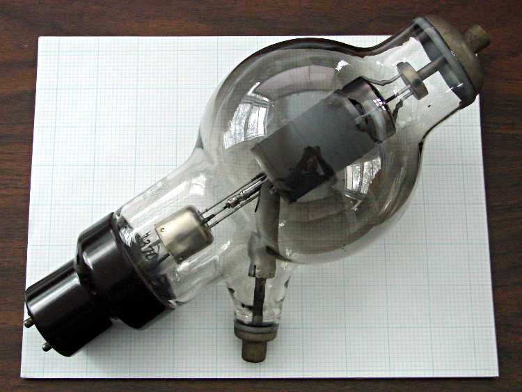
6C21 Triode
It’s a 6C21 triode, originally used as a radar modulator, atop a letter-size sheet of graph paper. The plate terminal is on top, the grid sticks out to the side, and the filament is common with the cathode through the base pins.
The gray film inside the bulb shows that it’s been used, but the filament still has continuity. Ordinarily, you could turn something like this into a night light by running the filament at a voltage somewhat under its rating, but my bench supply maxed out at @ 3 A without even warming it up; a dim orange night light that burns maybe 75 W is Not A Good Idea.
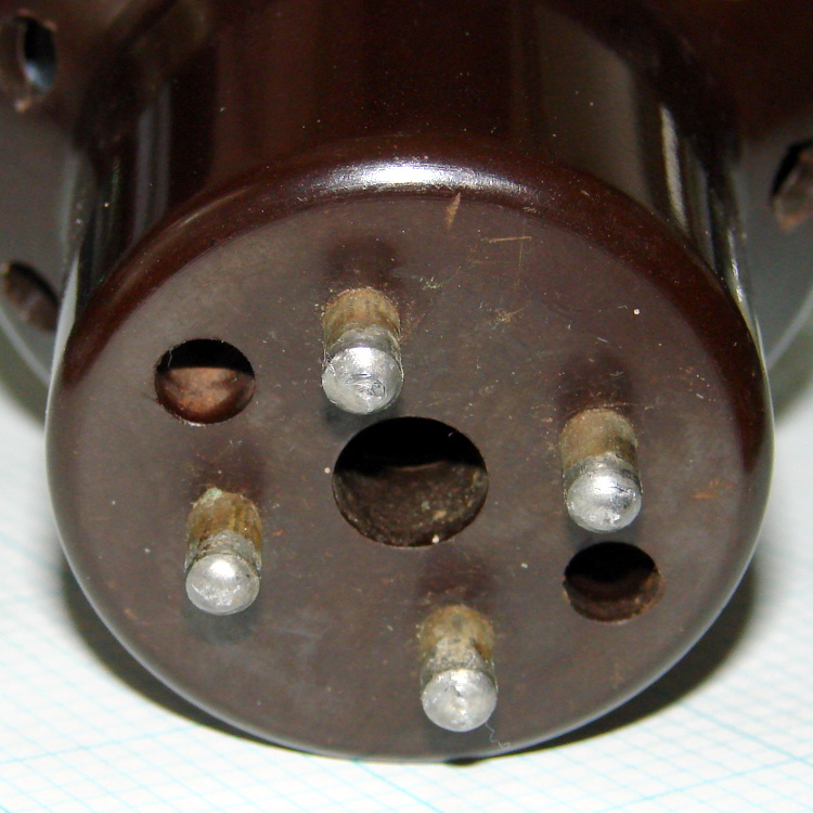
The base has some intriguing holes, originally used for forced-air cooling, that lead directly to the glass envelope:
6C21 Triode – base
One could mount discrete LEDs in those holes, maybe a slightly turned-down 10 mm cool-white LED in the middle flanked by red and blue, and run a low-power Arduino-based mood light; by some cosmic coincidence, the hole spacing matches up almost perfectly with those LED strips. Or one could go full analog with three red LEDs driven by the WWVB signal.
I’m thinking a plain black acrylic case, with the tube base sunk into the middle, would be about right. No readouts, no dials, no buttons, just a gently glowing tube.
Maybe a 3D printed socket holding everything in place?
A trio of 5 mW laser modules arrived with a bunch of other surplus gear after an end-of-year sale:
5 mW Laser Module
It runs on 5 V at 20 mA, determined by the 91 Ω SMD resistor soldered across the terminals at the back of the PCB. That suggests the laser diode itself runs at about 3.2 V: 5 V – 0.020 A * 91 Ω.
The brass case connects to the red (positive) wire, so you must insulate the laser module from the usual grounded metal chassis.
Two of the three lasers arrived badly defocused, but a twist of the brass barrel broke the sealing glue and a bit more twiddling found the sweet spot.
Running one of these from an Arduino would be just like the UV LED: redefine a bit in the shift register bitfield and drive the laser with a MOSFET switch.
I’d be tempted to bypass the SMD resistor and run it from an LM317-style current regulator hitched directly to the raw battery; I’m pretty sure I have some LM317 regulators in TO-92 packages. The sense resistor would be 62.5 Ω = 1.25 V / 0.02 A, dissipating 25 mW = 1.25 V * 20 mA. From a freshly charged 7.2 V Li-ion battery at 8.5 V, the regulator would dissipate something like 80 mW =(8.5 – 1.25 – 3.2 V) * 20 mA.
Or just add more series resistance and ignore the brightness variation?
A bit of fiddling with the Arduino PWM hardware can turn a white LED into a stroboscopic tachometer to chop smooth motion into chunks:
Strobe – Maze 1 – 50 Hz 100 us
I was moving that pendant by hand and slight speed changes were easily visible:
Strobe – Maze 2 – 50 Hz 100 us
IBMers of a certain era may recognize the test object; the rest of you can go there.
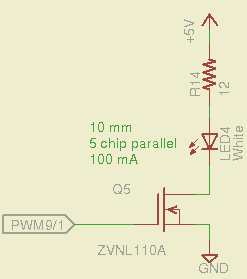
That’s a 10 mm warm-white LED with 5 parallel chips, running at about 100 mA from a 5 V supply, and driven from the same PWM channel and MOSFET that used to drive also drives the red channel of the RGB LED Mood Light:
White LED Strobe
The ZVNL110A MOSFET has a 3 Ω drain resistance, which becomes a significant part of the resistance; you’d want a bigger, better, lower resistance MOSFET to wring more light out of the LED. In fact, I ran the LED from 12 V with the same resistor at a few hundred mA.
The reason you need more light is to make up for the minuscule duty cycle. In order to “stop motion”, you want a very short pulse; I picked a 100 μs pulse. At 50 Hz, that works out to a 0.5% duty cycle: not much light at 100 mA, but OK for a demo.
You can’t do this with the standard Arduino PWM setup, because it produces a constant frequency (about 488 Hz) and varies the duty cycle; we need a variable frequency with a constant pulse length. Because a stroboscope needs fine-grained control over the frequency, in order to stop the motion of rotating objects, it should run from one of the 16 bit Timer1 PWM outputs, which means either PWM9 or PWM10. Note that simply changing the timer’s clock prescaler as described there won’t suffice, because that gives very coarse control of the PWM frequency.
It’s probably worth noting that trying to do precise timing purely in software with, say, the millis() and micros() functions, produces terrible results…
The Arduino timer hardware includes control over both the period and the duration of the output pulses. The Fine Manual describes all the timer configuration registers starting on page 109; see that post for a push-pull PWM driver that formed the basis of this one.
Fast PWM (Mode 14) has some useful characteristics:
Single-slope operation: timer counts only upward
Output PWM9 goes high when TCNT1 resets to 0
Output PWM9 goes low when TCNT1 = OCR1A
TCNT1 resets when TCNT1 = ICR1
The lowest possible output frequency occurs with ICR1 = 0xffff, so that Timer1 counts from 0x0000 to 0xffff before resetting (which, in that case, is indistinguishable from simply wrapping). The wrap period = ICR1 * tick period and the corresponding frequency = 1 / period.
The clock prescaler determines the overall range of Timer1 by setting the tick period. The Clock Select bit field can take on 6 useful, albeit widely separated, values (the other two select the external clock pin):
0 – stop timer
1 – prescale 1:1 = 62.5 ns tick → 244 Hz
2 – prescale 1:8 = 500 ns tick → 30 Hz
3 – prescale 1:64 = 4 μs tick → 3.8 Hz
4 – prescale 1:256 = 16 μs tick → 0.95 Hz
5 – prescale 1:1024 = 64 μs tick → 0.24 Hz
For my purposes, a lower limit around 4 Hz seemed about right. That means CS = 3, the prescaler runs at 1:64, and the timer ticks at 4 μs.
The frequency upper limit could be just under 1/(pulse width), which would produce a very high duty cycle. I arbitrarily set the limit to 1/(4 × pulse width), for a 25% duty cycle that works out to 1/(4 × 100 μs) = 2.5 kHz = 150 k flash/min. If you’re using very high current drive, then limit the duty cycle to prevent toasting the LED.
Because a strobe tach needs quick & easy adjustment, the encoder knob tweaks the pulse frequency in 1 Hz steps. Pushing the knob to close the shaft switch (if you have such a knob, of course, otherwise use another button; they all do the same thing here) reduces the step size to 0.01 Hz, which is more useful for fine tuning when you’re close to the goal. A real application requires better control over the numeric values (probably using integer values); I used floating point and simply ignored all the usual roundoff issues:
Shut off interrupts to prevent interference with the high byte storage register
Stop the timer: CS=0
Load the new upper limit in ICR1
Force TCNT1 to be just below IRC1 to terminate the current pulse
Start the timer: CS=3
Enable interrupts again
You’d probably plunk that into a separate function in a real program…
Printing the frequency becomes a hassle without floating point formatting in printf(). It should appear on the character LED display, too. Optionally / additionally showing the value in rev/min would be very nice.
You’d want to increment the frequency by some reasonable fraction of the current value, perhaps rounded to 1 / 2 / 5 / 10 percent steps. Larger steps by pushbutton? Truncate the current value to a multiple of the step size?
You would also want some way to adjust the flash duration, but that’s definitely in the nature of fine tuning.
As it stands, a 100 μs pulse really does stop motion:
Fan stopped at 2500 rpm
That’s a fan running at about 2500 rpm, with the LED flashing at 41.86 Hz. The camera exposure is 1/2 sec @ f/3.5, handheld, which means the camera integrated about 20 flashes. Ambient light accounts for the background blur: I boosted the grossly underexposed image right out of darkness. The square on the hub is retroreflective tape for a laser tachometer that verified the speed.
Yes, half a second handheld. The morning tea wears off during the day…
In round numbers, 41.86 Hz = 23.9 ms / rev. The fan diameter is 86 mm, so the blade tips travel 1.1 mm = (270 mm / 23.9 ms) × 100 μs during each flash. The tips seem slightly blurred when you (well, I) look very closely in real life, but I think this lashup worked pretty well right off the sketchpad.
The Arduino source code:
// Stroboscopic Tachometer
// Ed Nisley - KE4ANU - December 2012

//----------
// Pin assignments

const byte PIN_KNOB_A = 2;			// knob A switch - must be on ext interrupt 2
const byte PIN_KNOB_B = 4;			//  .. B switch
const byte PIN_BUTTONS = A5;		//  .. push-close momentary switches

const byte PIN_STROBE = 9;			// LED drive, must be PWM9 = OCR1A using Timer1

const byte PIN_PWM10 = 10;			// drivers for LED strip, must turn these off...
const byte PIN_PWM11 = 11;

const byte PIN_SYNC = 13;			// scope sync

//----------
// Constants

const int UPDATEMS = 10;				// update LEDs only this many ms apart

#define TCCRxB_CS 0x03					// Timer prescaler CS=3 -> 1:64 division

const float TICKPD = 64.0 * 62.5e-9;	// basic Timer1 tick rate: prescaler * clock

enum KNOB_STATES {KNOB_CLICK_0,KNOB_CLICK_1};

// ButtonThreshold must have N_BUTTONS elements, last = 1024

enum BUTTONS {SW_KNOB, B_1, B_2, B_3, B_4, N_BUTTONS};
const word ButtonThreshold[] = {265/2, (475+265)/2, (658+475)/2, (834+658)/2, (1023+834)/2, 1024};

//----------
// Globals

float FlashLength = 0.1e-3;						// strobe flash duration in seconds
word FlashLengthCt = FlashLength / TICKPD;		//  ... in Timer1 ticks

float FlashFreq = 20.0;							// strobe flash frequency in Hz
float FlashPd = 1.0 / FlashFreq;				//  ... period in sec
word FlashPdCt = FlashPd / TICKPD;				//  ... period in Timer1 ticks

float FreqIncr = 1.0;							// default frequency increment
const float FreqMin = 4.0;
const float FreqMax = 1.0/(4.0*FlashLength);

volatile char KnobCounter = 0;
volatile char KnobState;

byte Button, PrevButton;

unsigned long MillisNow;
unsigned long MillisThen;

//-- Helper routine for printf()

int s_putc(char c, FILE *t) {
  Serial.write(c);
}

//-- Knob interrupt handler

void KnobHandler(void)
{
	byte Inputs;
	Inputs = digitalRead(PIN_KNOB_B) << 1 | digitalRead(PIN_KNOB_A);  // align raw inputs
//	Inputs ^= 0x02;                             // fix direction

	switch (KnobState << 2 | Inputs) {
	case 0x00 : 				// 0 00 - glitch
        break;
	case 0x01 : 				 // 0 01 - UP to 1
        KnobCounter++;
		KnobState = KNOB_CLICK_1;
		break;
	case 0x03 : 				 // 0 11 - DOWN to 1
        KnobCounter--;
		KnobState = KNOB_CLICK_1;
		break;
	case 0x02 : 				 // 0 10 - glitch
        break;
	case 0x04 : 				 // 1 00 - DOWN to 0
        KnobCounter--;
		KnobState = KNOB_CLICK_0;
		break;
	case 0x05 : 				 // 1 01 - glitch
        break;
	case 0x07 : 				 // 1 11 - glitch
        break;
	case 0x06 : 				 // 1 10 - UP to 0
        KnobCounter++;
		KnobState = KNOB_CLICK_0;
		break;
	default :  					// something is broken!
        KnobCounter = 0;
		KnobState = KNOB_CLICK_0;
	}
}

//-- Read and decipher analog switch inputs
//		returns N_BUTTONS if no buttons pressed

byte ReadButtons(int PinNumber) {

word RawButton;
byte ButtonNum;

	RawButton = analogRead(PinNumber);

	for (ButtonNum = 0; ButtonNum <= N_BUTTONS; ButtonNum++){
		if (RawButton < ButtonThreshold[ButtonNum])
			break;
	}

	return ButtonNum;

}

//------------------
// Set things up

void setup() {
	pinMode(PIN_SYNC,OUTPUT);
	digitalWrite(PIN_SYNC,LOW);	// show we arrived

	analogWrite(PIN_PWM10,0);			// turn off other PWM outputs
	analogWrite(PIN_PWM11,0);

	analogWrite(PIN_STROBE,1);			// let Arduino set up default Timer1 PWM
	TCCR1B = 0;							// turn off Timer1 for strobe setup
	TCCR1A = 0x82;						// clear OCR1A on match, Fast PWM, lower WGM1x = 14
	ICR1 = FlashPdCt;
	OCR1A = FlashLengthCt;
	TCNT1 = FlashLengthCt - 1;
	TCCR1B = 0x18 | TCCRxB_CS;			// upper WGM1x = 14, Prescale 1:64, start Timer1

	pinMode(PIN_KNOB_B,INPUT_PULLUP);
	pinMode(PIN_KNOB_A,INPUT_PULLUP);

	KnobState = digitalRead(PIN_KNOB_A);
	Button = PrevButton = ReadButtons(PIN_BUTTONS);

	attachInterrupt((PIN_KNOB_A - 2),KnobHandler,CHANGE);

	Serial.begin(9600);
	fdevopen(&s_putc,0);				// set up serial output for printf()

	printf("Stroboscope Tachometer\r\nEd Nisley - KE4ZNU - December 2012\r\n");

	printf("Frequency: %d.%02d\nPulse duration: %d us\n",
		   (int)FlashFreq,(int)(100.0 * (FlashFreq - trunc(FlashFreq))),
		   (int)(1e6 * FlashLength));

	MillisThen = millis();

}

//------------------
// Run the test loop

void loop() {

	MillisNow = millis();

	if ((MillisNow - MillisThen) > UPDATEMS) {

		digitalWrite(PIN_SYNC,HIGH);

		Button = ReadButtons(PIN_BUTTONS);
		if (PrevButton != Button) {
			if (Button == N_BUTTONS) {
//				printf("Button %d released\n",PrevButton);
				FreqIncr = 1.0;
			}
			else
//				printf("Button %d pressed\n",Button);
//				if (Button == SW_KNOB)
					FreqIncr = 0.01;
			PrevButton = Button;
		}

		if (KnobCounter) {
			FlashFreq += (float)KnobCounter * FreqIncr;
			KnobCounter = 0;

			FlashFreq = constrain(FlashFreq,FreqMin,FreqMax);
			FlashFreq = round(100.0 * FlashFreq) / 100.0;

			FlashPd = 1.0 / FlashFreq;
			FlashPdCt = FlashPd / TICKPD;

			noInterrupts();
			TCCR1B &= 0xf8;				// stop Timer1
			ICR1 = FlashPdCt;			// set new period
			TCNT1 = FlashPdCt - 1;		// force immediate update
			TCCR1B |= TCCRxB_CS;		// start Timer1
			interrupts();

			printf("Frequency: %d.%02d\n",
				   (int)FlashFreq,(int)(100.0 * (FlashFreq - trunc(FlashFreq))));
		}

		digitalWrite(PIN_SYNC,LOW);

		MillisThen = MillisNow;
	}

}
That’s a grandiose name for a blinking LED, if I ever saw one…
While wiring up the LED stress tester, I realized I should abuse a string of amber LEDs along with the three red strings. Herewith, four amber LEDs from the top of their bag, with LED 5 = LED 1 retested:
Amber LEDs – 100 mA
Apart from being an outlier, that red trace seems much prettier than the others, doesn’t it?
The Bash / Gnuplot routine that produced the graph has a few tweaks:
#!/bin/sh
numLEDs=4
#-- overhead
export GDFONTPATH="/usr/share/fonts/truetype/"
base="${1%.*}"
echo Base name: ${base}
ofile=${base}.png
echo Input file: $1
echo Output file: ${ofile}
#-- do it
gnuplot << EOF
#set term x11
set term png font "arialbd.ttf" 18 size 950,600
set output "${ofile}"
set title "${base}"
set key noautotitles
unset mouse
set bmargin 4
set grid xtics ytics
set xlabel "Forward Voltage - V"
set format x "%6.3f"
set xrange [1.8:2.2]
#set xtics 0,5
set mxtics 2
#set logscale y
#set ytics nomirror autofreq
set ylabel "Current - mA"
set format y "%4.0f"
set yrange [0:120]
set mytics 2
#set y2label "right side variable"
#set y2tics nomirror autofreq 2
#set format y2 "%3.0f"
#set y2range [0:200]
#set y2tics 32
#set rmargin 9
set datafile separator "\t"
set label 1 "LED 1 = LED $((numLEDs + 1))" at 2.100,110 right font "arialbd,18"
set arrow from 2.100,110 to 2.105,103 lt 1 lw 2 lc 0
plot	\
    "$1" index 0:$((numLEDs - 1)) using (\$5/1000):(\$2/1000):(column(-2)) with linespoints lw 2 lc variable,\
    "$1" index $numLEDs using (\$5/1000):(\$2/1000) with linespoints lw 2 lc 0
EOF
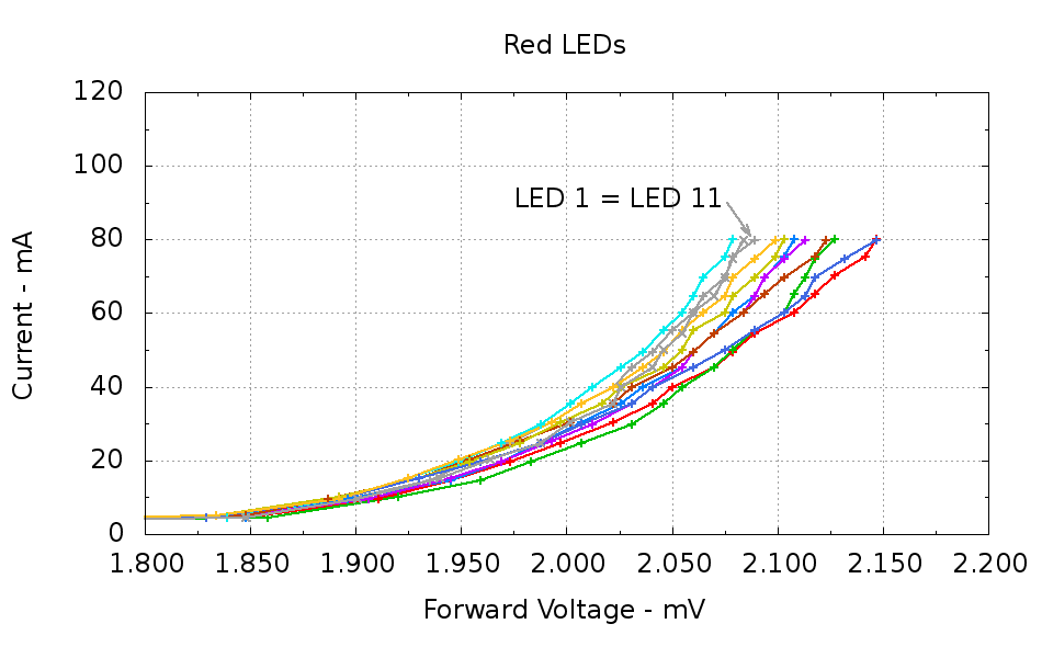
Running ten random red LEDs (taken from the bag of 100 sent halfway around the planet) through the LED Curver Tracer produces this plot:
Red LEDs – 80 mA
The two gray traces both come from LED 1 to verify that the process produces the same answer for the same LED. It does, pretty much.
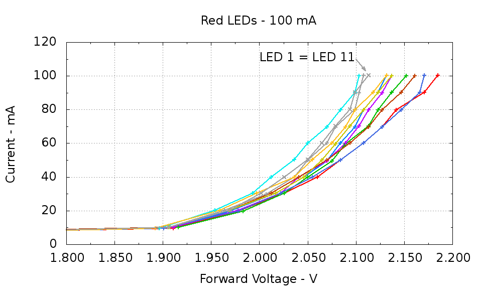
Repeating that with the same LEDs in the same order, but stepping 10 mA up to 100 mA produces a similar plot:
Red LEDs – 100 mA
The voltage quantization comes from the Arduino’s 5 mV ADC resolution (the readings are averaged, but there’s actually not much noise) and the current quantization comes from the step value in the measurement loop (5 mA in the first plot, 10 mA in the second). Seeing the LEDs line up mostly the same way at 80 mA in both graphs is comforting, as it suggests the measurement results aren’t completely random numbers.
Putting three red LEDs in series could produce a total forward drop anywhere between 6.309 V (3*2.103) and 6.555 V (3*2.185), a difference of nigh onto a quarter volt, if you assume this group spans the entire range of voltages and the whole collection has many duplicate values and you’re remarkably unlucky while picking LEDs. For this particular set, however, summing three successive groups of three produces 6.445, 6.372, and 6.469 V, for a spread of just under 100 mV. That suggests it’s probably not worthwhile to select LEDs for forward voltage within each series group of three, although matching parallel LEDs makes a lot of sense. I have no confidence the values will remain stable over power-on hours / thermal cycling / current stress.
The capacity plot for the Wouxun KG-UV3D lithium battery packs shows that there’s not a lot of capacity left after 7.0 V, so shutting down or scaling back to lower current wouldn’t be a major loss. However, it’s not clear a fixed resistor will do a sufficient job of current limiting with 6.5 V forward voltage across the LED string:
At 7.5 V, 100 mA calls for 10 Ω (drop 1 V at 100 mA)
At 8.2 V, 10 Ω produces 170 mA (1.7 V across 10 Ω)
At 7.0 V, 10 Ω produces 50 mA (0.5 V across 10 Ω)
Obviously, 170 mA is way too much, even by my lax standards.
A 100 mV variation in forward voltage between stacks, each with a 10 Ω resistor, translates into about 10 mA difference in current. This may actually call for current sensors and direct current control, although using a sensor per string, seems excessive. Low dropout regulators in current-source mode might suffice, but that still seems messy.
The test rig will run from a hard 7.5 V supply, which means I can use fixed resistors and be done with it.
The raw data behind those graphs, with LED 1 and LED 11 being the same LED:
#!/bin/sh
#-- overhead
export GDFONTPATH="/usr/share/fonts/truetype/"
base="${1%.*}"
echo Base name: ${base}
ofile=${base}.png
echo Input file: $1
echo Output file: ${ofile}
#-- do it
gnuplot << EOF
#set term x11
set term png font "arialbd.ttf" 18 size 950,600
set output "${ofile}"
set title "${base}"
set key noautotitles
unset mouse
set bmargin 4
set grid xtics ytics
set xlabel "Forward Voltage - V"
set format x "%6.3f"
set xrange [1.8:2.2]
#set xtics 0,5
set mxtics 2
#set logscale y
#set ytics nomirror autofreq
set ylabel "Current - mA"
set format y "%4.0f"
set yrange [0:120]
set mytics 2
#set y2label "right side variable"
#set y2tics nomirror autofreq 2
#set format y2 "%3.0f"
#set y2range [0:200]
#set y2tics 32
#set rmargin 9
set datafile separator "\t"
set label 1 "LED 1 = LED 11" at 2.100,110 right font "arialbd,18"
set arrow from 2.100,110 to 2.110,103 lt 1 lw 2 lc 0
plot    \
"$1" index 0:9 using (\$5/1000):(\$2/1000):(column(-2)) with linespoints lw 2 lc variable,\
"$1" index 10 using (\$5/1000):(\$2/1000) with linespoints lw 2 lc 0
EOF
And the Arduino source code, which bears a remarkable resemblance to the original firmware:
// LED Curve Tracer
// Ed Nisley - KE4ANU - December 2012

#include <stdio.h>

//----------
// Pin assignments

const byte PIN_READ_LEDSUPPLY = 0;    // AI - LED supply voltage        blue
const byte PIN_READ_VDRAIN = 1;        // AI - drain voltage            red
const byte PIN_READ_VSOURCE = 2;    // AI - source voltage            orange
const byte PIN_READ_VGATE = 3;        // AI - VGS after filtering        violet

const byte PIN_SET_VGATE = 11;        // PWM - gate voltage            brown

const byte PIN_BUTTON1 = 8;            // DI - button to start tests    green
const byte PIN_BUTTON2 = 7;            // DI - button for options        yellow

const byte PIN_HEARTBEAT = 13;        // DO - Arduino LED
const byte PIN_SYNC = 2;            // DO - scope sync output

//----------
// Constants

const int MaxCurrent = 100;                // maximum LED current - mA
const int ISTEP = 10;                    // LED current increment

const float Vcc = 4.930;                // Arduino supply -- must be measured!

const float RSense = 10.500;            // current sense resistor

const float ITolerance = 0.0005;        // current setpoint tolerance

const float VGStep = 0.019;                // increment/decrement VGate = 5 V / 256

const byte PWM_Settle = 5;                // PWM settling time ms

#define TCCRxB 0x01                        // Timer prescaler = 1:1 for 32 kHz PWM

#define MK_UL(fl,sc) ((unsigned long)((fl)*(sc)))
#define MK_U(fl,sc) ((unsigned int)((fl)*(sc)))

//----------
// Globals

float AVRef1V1;                    // 1.1 V bandgap reference - calculated from Vcc

float VccLED;                    // LED high-side supply

float VDrain;                    // MOSFET terminal voltages
float VSource;
float VGate;

unsigned int TestNum = 1;

long unsigned long MillisNow;

//-- Read AI channel
//      averages several readings to improve noise performance
//        returns value in mV assuming VCC ref voltage

#define NUM_T_SAMPLES    10

float ReadAI(byte PinNum) {

word RawAverage;

digitalWrite(PIN_SYNC,HIGH);                // scope sync

RawAverage = analogRead(PinNum);            // prime the averaging pump

for (int i=2; i <= NUM_T_SAMPLES; i++) {
RawAverage += (word)analogRead(PinNum);
}

digitalWrite(PIN_SYNC,LOW);

RawAverage /= NUM_T_SAMPLES;

return Vcc * (float)RawAverage / 1024.0;

}

//-- Set PWM output

void SetPWMVoltage(byte PinNum,float PWMVolt) {

byte PWM;

PWM = (byte)(PWMVolt / Vcc * 255.0);

analogWrite(PinNum,PWM);
delay(PWM_Settle);

}

//-- Set VGS to produce desired LED current
//        bails out if VDS drops below a sensible value

void SetLEDCurrent(float ITarget) {

float ISense;                // measured current
float VGateSet;            // output voltage setpoint
float IError;                // (actual - desired) current

VGate = ReadAI(PIN_READ_VGATE);                    // get gate voltage
VGateSet = VGate;                                    //  because input may not match output

do {

VSource = ReadAI(PIN_READ_VSOURCE);
ISense = VSource / RSense;                        // get LED current

//    printf("\r\nITarget: %lu mA",MK_UL(ITarget,1000.0));
IError = ISense - ITarget;

//    printf("\r\nISense: %d mA VGateSet: %d mV VGate %d IError %d mA",
//           MK_U(ISense,1000.0),
//           MK_U(VGateSet,1000.0),
//           MK_U(VGate,1000.0),
//           MK_U(IError,1000.0));

if (IError < -ITolerance) {
VGateSet += VGStep;
//      Serial.print('+');
}
else if (IError > ITolerance) {
VGateSet -= VGStep;
//      Serial.print('-');
}

VGateSet = constrain(VGateSet,0.0,Vcc);
SetPWMVoltage(PIN_SET_VGATE,VGateSet);

VDrain = ReadAI(PIN_READ_VDRAIN);        // sample these for the main loop
VGate = ReadAI(PIN_READ_VGATE);
VccLED = ReadAI(PIN_READ_LEDSUPPLY);

if ((VDrain - VSource) < 0.020) {            // bail if VDS gets too low
printf("# VDS=%d too low, bailing\r\n",MK_U(VDrain - VSource,1000.0));
break;
}

} while (abs(IError) > ITolerance);

//    Serial.println(" Done");
}

//-- compute actual 1.1 V bandgap reference based on known VCC = AVcc (more or less)
//        adapted from http://code.google.com/p/tinkerit/wiki/SecretVoltmeter

float ReadBandGap(void) {

word ADCBits;
float VBandGap;

ADMUX = _BV(REFS0) | _BV(MUX3) | _BV(MUX2) | _BV(MUX1);    // select 1.1 V input
delay(2); // Wait for Vref to settle

ADCSRA |= _BV(ADSC);                                        // Convert
while (bit_is_set(ADCSRA,ADSC));

ADCBits = ADCL;
ADCBits |= ADCH<<8;

VBandGap = Vcc * (float)ADCBits / 1024.0;
return VBandGap;
}

//-- Print message, wait for a given button press

void WaitButton(int Button,char *pMsg) {
printf("# %s",pMsg);
while(HIGH == digitalRead(Button)) {
delay(100);
digitalWrite(PIN_HEARTBEAT,!digitalRead(PIN_HEARTBEAT));
}

delay(50);                // wait for bounce to settle
digitalWrite(PIN_HEARTBEAT,LOW);
}

//-- Helper routine for printf()

int s_putc(char c, FILE *t) {
Serial.write(c);
}

//------------------
// Set things up

void setup() {
pinMode(PIN_HEARTBEAT,OUTPUT);
digitalWrite(PIN_HEARTBEAT,LOW);    // show we arrived

pinMode(PIN_SYNC,OUTPUT);
digitalWrite(PIN_SYNC,LOW);        // show we arrived

TCCR1B = TCCRxB;                    // set frequency for PWM 9 & 10
TCCR2B = TCCRxB;                    // set frequency for PWM 3 & 11

pinMode(PIN_SET_VGATE,OUTPUT);
analogWrite(PIN_SET_VGATE,0);        // force gate voltage = 0

pinMode(PIN_BUTTON1,INPUT_PULLUP);    // use internal pullup for buttons
pinMode(PIN_BUTTON2,INPUT_PULLUP);

Serial.begin(9600);
fdevopen(&s_putc,0);                // set up serial output for printf()

printf("# LED Curve Tracer\r\n# Ed Nisley - KE4ZNU - December 2012\r\n");

VccLED = ReadAI(PIN_READ_LEDSUPPLY);
printf("# VCC at LED: %d mV\r\n",MK_U(VccLED,1000.0));

AVRef1V1 = ReadBandGap();            // compute actual bandgap reference voltage
printf("# Bandgap reference voltage: %lu mV\r\n",MK_UL(AVRef1V1,1000.0));

}

//------------------
// Run the test loop

void loop() {

Serial.println('\n');                        // blank line for Gnuplot indexing

WaitButton(PIN_BUTTON1,"Insert LED, press button 1 to start...\r\n");
printf("# INOM\tILED\tVccLED\tVD\tVLED\tVG\tVS\tVGS\tVDS\t<--- LED %d\r\n",TestNum++);
digitalWrite(PIN_HEARTBEAT,LOW);

for (int ILED=0; ILED <= MaxCurrent; ILED+=ISTEP) {
SetLEDCurrent(((float)ILED)/1000.0);
printf("%d\t%lu\t%d\t%d\t%d\t%d\t%d\t%d\t%d\r\n",
ILED,
MK_UL(VSource / RSense,1.0e6),
MK_U(VccLED,1000.0),
MK_U(VDrain,1000.0),
MK_U(VccLED - VDrain,1000.0),
MK_U(VGate,1000.0),
MK_U(VSource,1000.0),
MK_U(VGate - VSource,1000),
MK_U(VDrain - VSource,1000.0)
);
}

SetPWMVoltage(PIN_SET_VGATE,0.0);

}
I want to stress-test some LEDs for the long-stalled bike taillight project with a high current / low duty cycle drive. The usual specs give something like 100 mA at 10% duty cycle in a 100 μs period, but maybe they’ll withstand more abuse than that; I don’t have any specs whatsoever for these LEDs. The usual DC rating is 20 mA, so 100 mA at 20%, say 2 ms in a 10 ms period, should give the same average power as the DC spec. I plan to run them continuously until some failures to pop up or it’s obvious they’re doing just fine.
Although this would be a dandy Arduino project, a classic 555 timer IC makes more sense for something that must run continuously without changing anything. The usual 555 circuit restricts the duty cycle to more than 50% for high-active pulses, a bit over the 20% this task calls for. The simplest workaround is a Schottky diode across the discharge resistor to separate the two current paths: charge uses the upper resistor, discharge the lower, with the diode forward drop thrown in to complicate the calculations.
Rather than putz around with calculation, a few minutes iterating with Linear Technologies’ LTSpice IV produces a reasonable result:
NE555 pulse generator
In round numbers, a 1 μF timing capacitor, 2.7 kΩ charge resistor, and 13 kΩ discharge resistor do the trick. Given the usual capacitor tolerances, each resistor should include a twiddlepot of about half the nominal value: 1 kΩ and 5 kΩ, respectively.
I’m thinking of repurposing those Wouxun KG-UV3D batteries for this task and found a 7.5 V 3.5 A wall wart in the heap that will be close enough for the test rig. The 555 output should drive a logic-level MOSFET just fine, although even an ordinary FET would probably be OK for the relatively low current required for LED toasting.
The epoxy usually has some fluorescence, but this seems more dramatic than usual. In any event, the die’s wide beam angle shows clearly; the beam along the axis out in front is actually pretty tight.
It’s sitting on the back of a white ceramic tile and the colors came out surprisingly close to real life.
Adding this to an Arduino would follow the same logic as, say, the pager motor: power the LED + resistor + MOSFET from a +5 V external regulator that won’t heat the Arduino board, then define an unused bit in the shift register as, say UV_LED.