Ed Nisley's Blog: Shop notes, electronics, firmware, machinery, 3D printing, laser cuttery, and curiosities. Contents: 100% human thinking, 0% AI slop.
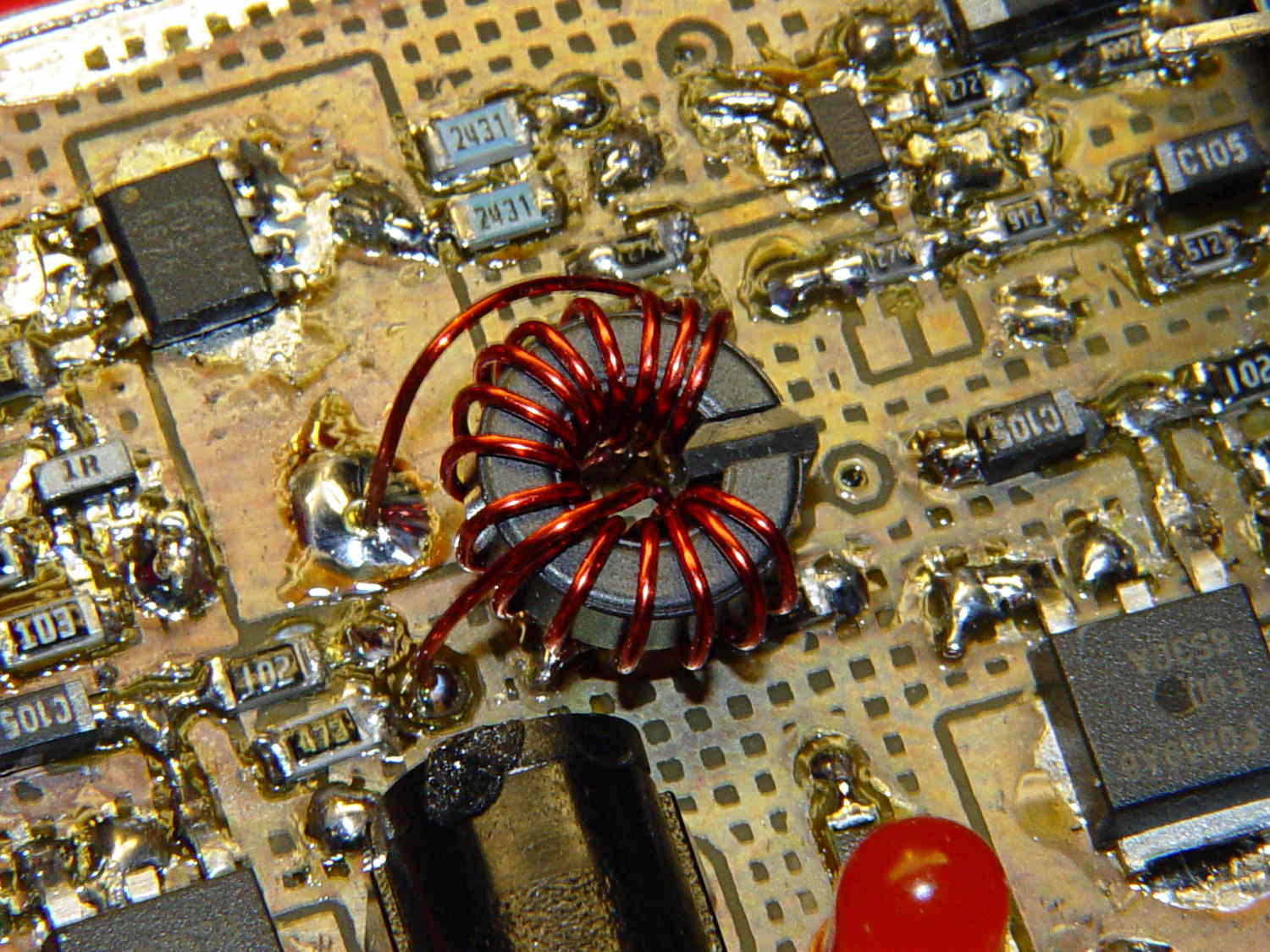
Although it’s not obvious, the two blue 2431 Ω resistors just above the toroid are a divider that scales the switched battery voltage (from the p-MOSFET on their left) by 50% and sends it to input A0 on the Arduino Pro Mini board:
Figuring the actual battery voltage is straightforward:
get 10 bit ADC value with analogRead()
multiply by actual VCC (measured at 4.96 V for this board)
divide by actual voltage divider ratio (measured at 3.78/7.57)
Which, of course, reported the battery voltage was 4.116 V. Huh?
After spending far too much time poking the code with a sharp stick, I wired the divider to the (previously unused) A6 and A7 inputs and dumped the raw ADC counts for all three. The answer should be somewhere near 763, but the three values came out around 215, 667, and 750. Huh?
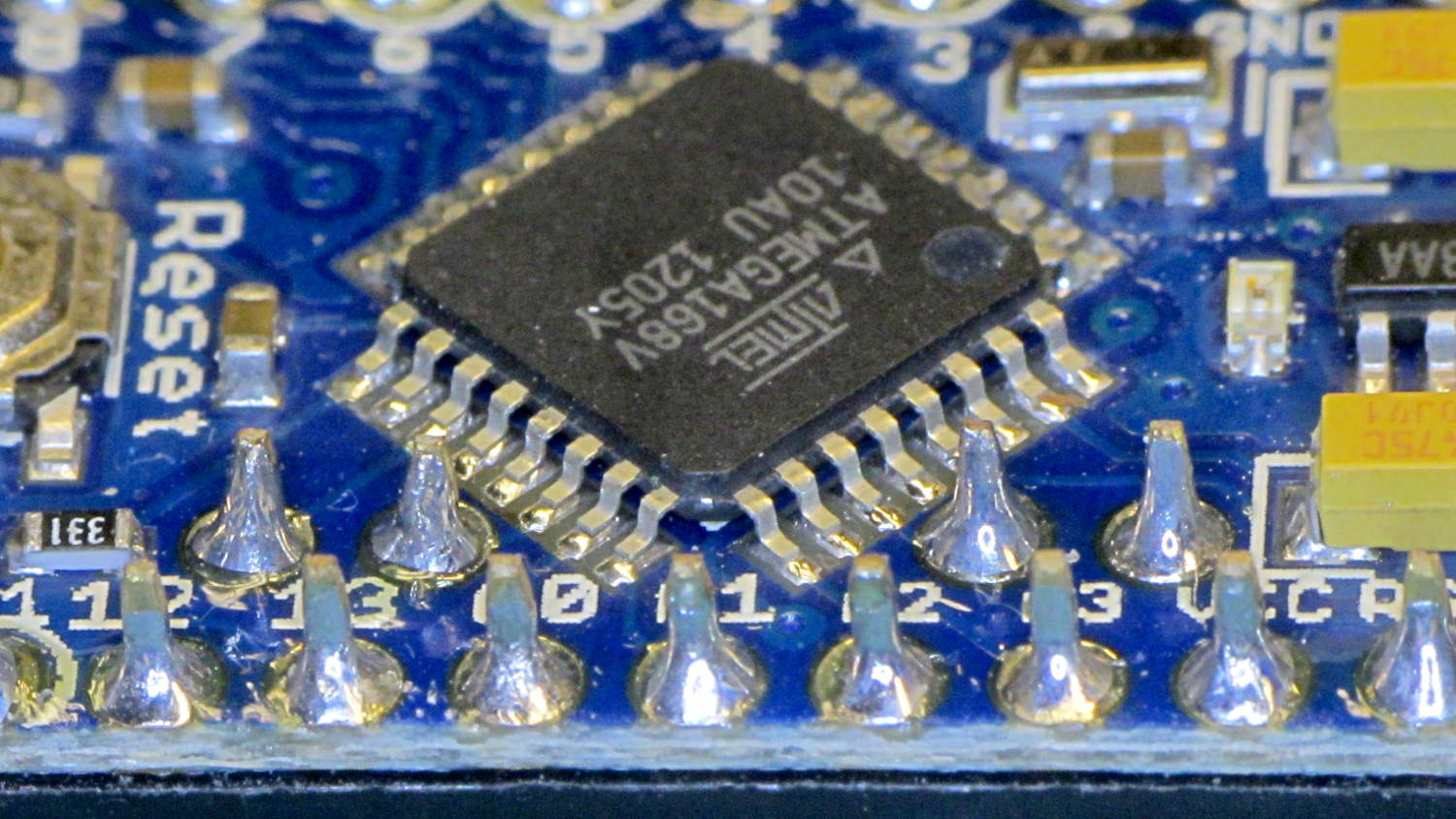
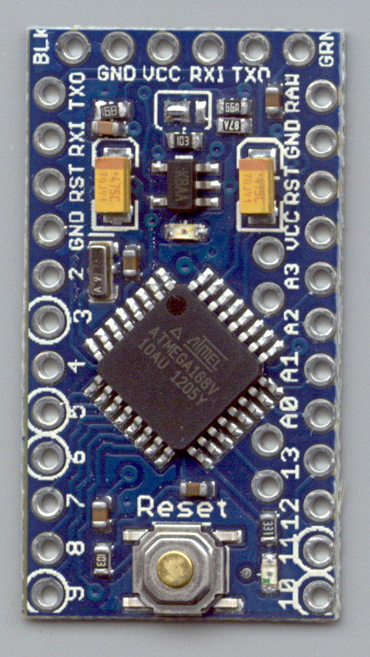
The A0 value is totally bogus, so I finally looked at the Arduino Pro Mini board:
Arduino Pro Mini clone – chip overview
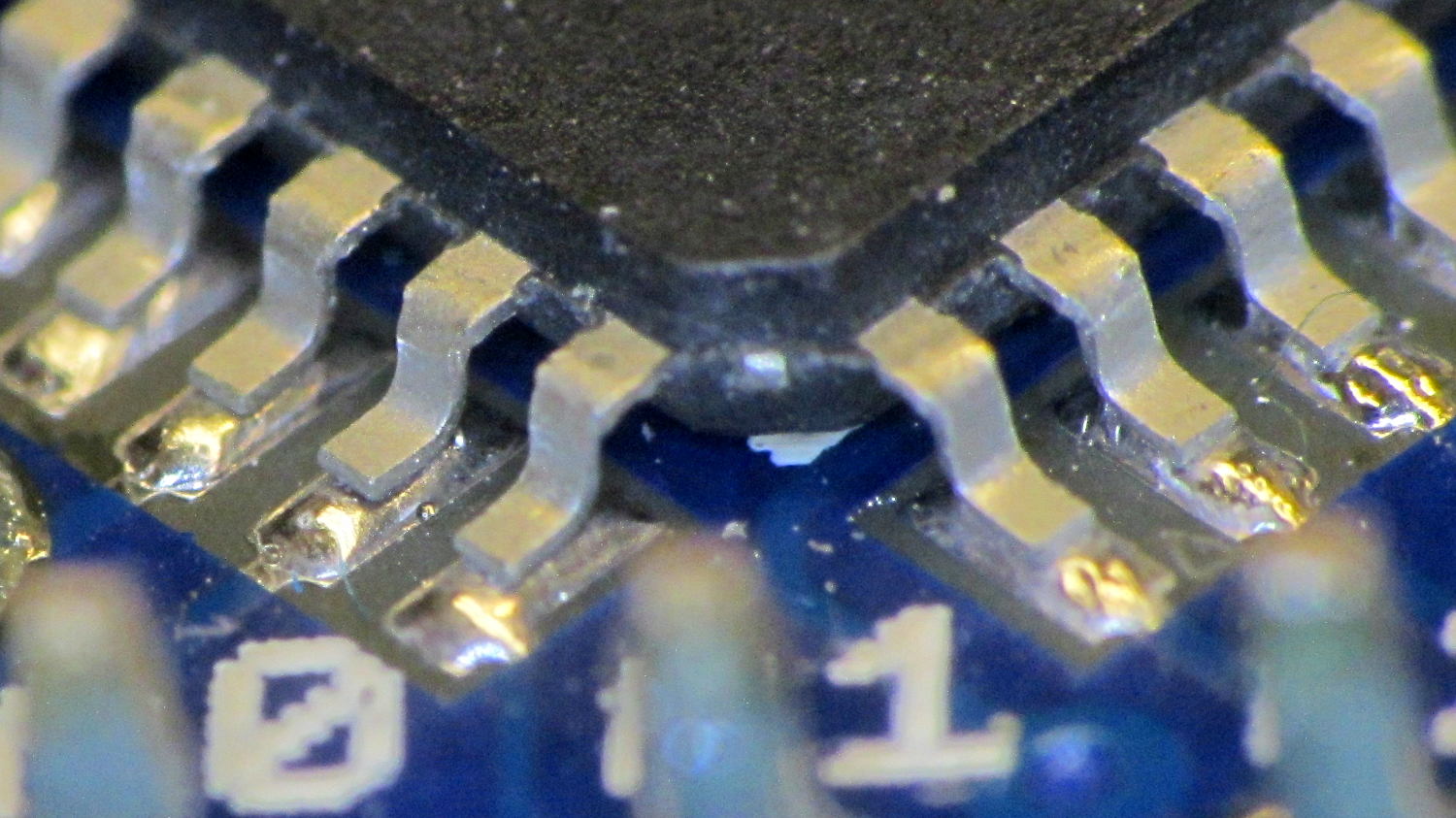
Hmmm. It turns out A0 is the second pin back on the left side:
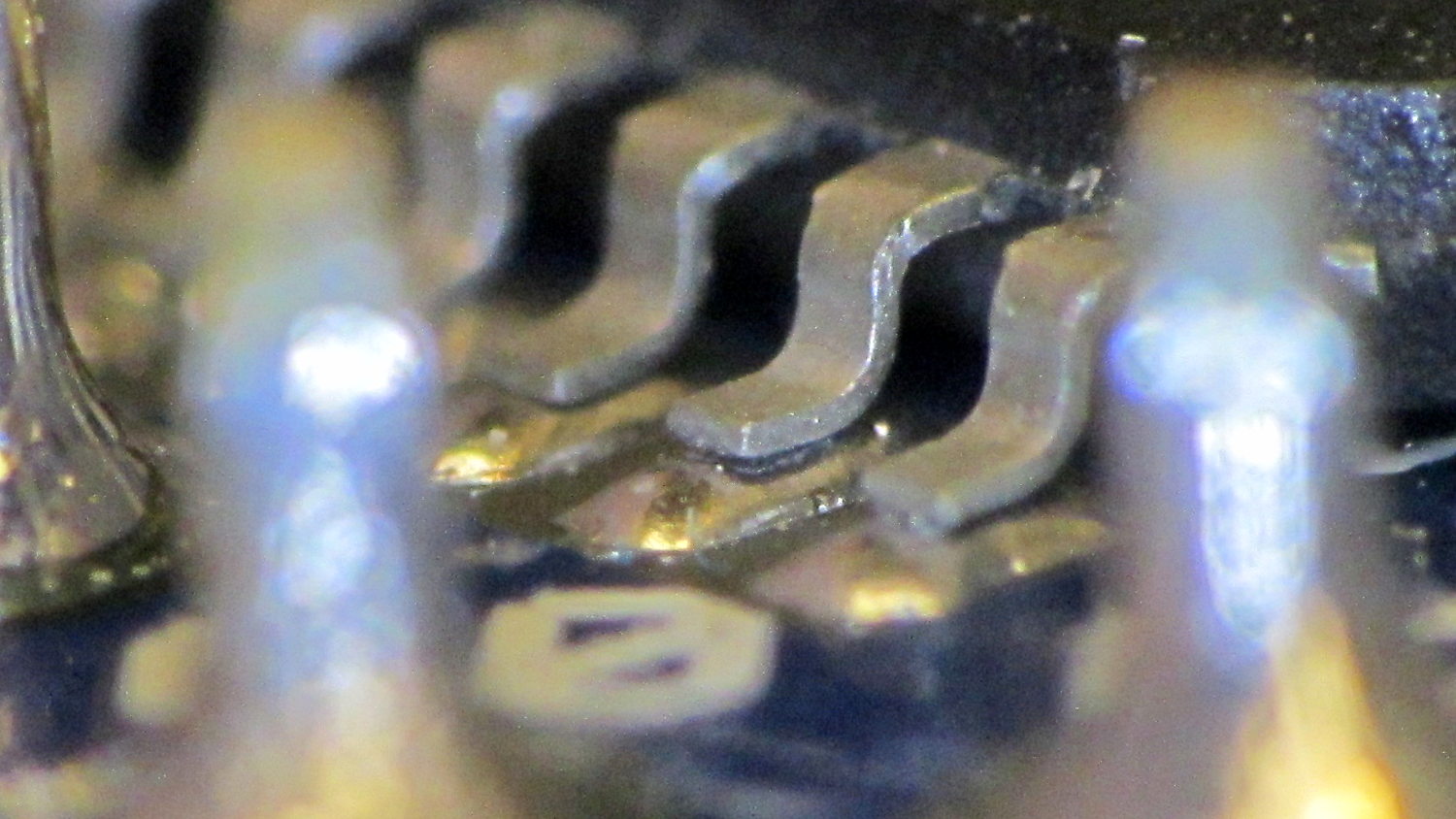
I slathered flux on all the pins, touched each one with a soldering iron, and it’s all good.
This is a knockoff Arduino Pro Mini board from eBay, of course, and the rest of the boards in that lot were OK. Their QC inspection almost certainly boils down to running the Blink sketch: if the LED blinks after the power goes on, ship it!
Blink doesn’t verify the analog inputs, which turn out to be wrapped around that corner of the package.
The improved platform for the M2 runs at 30 V, but the RAMBo board specs limit the max HBP voltage to 24 V, presumably because the 15 A ATO fuse won’t clear a high-voltage, high amperage DC short. While setting up the SSR that drives the new platform, I looked up the specs for the PSMN7R0-60YS MOSFET controlling the bed heater and … it doesn’t have a logic level gate.
The rDS spec is an impressive 6.4 mΩ max, but that’s at VGS = 10 V. The 1 mA threshold voltage VGS(th) = 4 V max, which means there’s only 1 V of headroom to turn the transistor on enough to pass upwards of 10 A.
The typical ID vs. VGS curve (Fig 6) shows 20 A at maybe 4.2 V, but the typical RDSon curve (Fig 8) shows the resistance skyrocketing for VGS under maybe 4.8 V; sliding that curve a wee bit to the right would cause a Very Bad Thing to take place.
A 20 mΩ resistance dissipates 4.5 W at 15 A, which seems rather aggressive for the small PCB copper-pour heatsink on the RAMBo board. It’s a somewhat more bearable 2 W at 10 A, but I think that’s still too high. Of course, the typical dissipation will should be much lower…
A good engineering rule of thumb is to ignore the datasheet’s “Typical” column and design using the “Minimum” or “Maximum” columns, as appropriate. When you depend on typical specs, getting “the same part” from a different supplier can provide a real education in supply-chain management.
I suspect tolerance stacking works well enough that nearly all the MOSFETs on nearly all the RAMBo boards run cool enough to survive, but I’d rather see logic-level MOSFETs in Arduino circuits where the maximum gate voltage won’t ever get above 5 V.
This may not look like much, but it’s the first test of the p-MOSFET power switch that completely kills power to the Arduino Pro Mini board and the Hall Effect LED Blinky Light:
Power off – 30 mA load
The top trace is the base drive to the NPN transistor that holds the p-MOSFET on while the Arduino is running. When it’s time to shut off, the Arduino drops the base drive output, the MOSFET turns off, and the switched battery voltage in the bottom trace drops like a rock. The current is about 30 mA when the Arduino is running and immeasurably low when it’s off; the MOSFET spec says it’s less than 1 μA, which is fine with me.
The PCB has those components clustered in the upper left corner, with the Arduino Pro Mini perched on header pins to the right:
Hall LED PCB – power switch test
The test code is a crudely hacked version of the canonical Blink sketch that waits 5 s after it starts running, then pulls the plug:
// Modified from Arduino Blink example
// Drives external p-MOSFET power switch
// Ed Nisley - KE4ZNU - Sep 2013

int led = 13;

// HIGH to enable power supply
int PowerOn = 4;

// HIGH to light Status LED
int Status = 10;

unsigned long MillisThen;

void setup() {

  pinMode(led, OUTPUT);

  pinMode(PowerOn,OUTPUT);
  digitalWrite(PowerOn,HIGH);
  pinMode(Status,OUTPUT);
  digitalWrite(Status,HIGH);

MillisThen = millis();
}

void loop() {
  digitalWrite(led, HIGH);
  delay(100);
  digitalWrite(led, LOW);
  delay(500);

  if (((millis() - MillisThen) > 5000ul)) {
      digitalWrite(Status,LOW);
      delay(50);
      digitalWrite(PowerOn,LOW);
      digitalWrite(Status,HIGH);
  }
}
It turns out that the Arduino runtime has a several-second delay after power comes up before the setup() routine starts running, so brief pulses from a vibration switch won’t last long enough to turn the thing on. That’s not a fatal flaw for now and, in fact, having to hold the power button in for a few seconds isn’t entirely a Bad Thing.
However, once the power turns on, a vibration switch could trigger an Arduino interrupt pin to reset a power-off timer. I’d be tempted to put the vibration switch in parallel with the button, with a pair of steering diodes that isolate the raw battery from the input pin.
This is, of course, a pure electronic implementation of a Useless Machine…
The Basement Warehouse Wing has an essentially unlimited supply of pristine CD cases (remember CDs?) that, with a bit of deft bandsaw work, will each emit a pair of 4×4 inch sheets of perfectly transparent acrylic plastic. The sheets are about 1.3 mm = 50 mils thick, which is just about exactly what you want for a Nixie-style display that doesn’t require high voltages, because you can edge-light a sheet with 0603 amber SMD LEDs. Obviously, this is not a Shining New Idea, but this post collects my doodles so they don’t get lost along the way.
The Squidwrench StickerLab session prodded me into lashing a prototype together to see how this would work; they have a Silhouette Cameo vinyl cutter driven with Robotcut that works well. I’d hoped to do some laser cutting at the subsequent session, but our schedules didn’t mesh.
The compelling advantage of laser cutting is that you could crack the CD cases apart, throw out the CD holder gimcrackery, lay the sheets flat on the cutter table with the latches & other junk upward, and burn the digits out of the middle without any further preparation. I think I could get much the same effect, at least for a crude prototype, by milling & engraving with the Sherline.
The sheets are about 4 threads of 3D printed plastic extruded at the M2’s default 0.4 mm width. You could print a black baseplate with slots to hold the sheets, put two threads between each sheet, and have the sheet 6 threads apart on center = 2.4 mm spacing:
Tab vs 3D thread size doodle
Ten such sheets would produce a standard 0-to-9 display about an inch deep, plus protective sheets front and back, so the whole affair would be maybe 1.25 inch deep. You’d probably want to offset the tabs on adjacent sheets to reduce light leakage between LEDs. The baseplate fits atop a PCB with LEDs at the right locations, so you get an opaque holder for the sheets that’s easy to produce and easy to assemble:
Sheet tab layout doodle
If you were clever, you could have different tab locations on each sheet so they’d fit only in the proper orientation; that might be important for cough mass production.
The M2 has a platform big enough to build an entire clock base in one pass, plus a matching piece to capture the tops of the digits. I think edge-lit acrylic needs a complete opaque surround for each digit sheet to block light leaking from the edges; it might be easier to build the mount in the other direction, lying flat on the platform, stack the mounts together with the digit sheets, then bolt the whole assembly from the front; that would ensure perfect alignment of everything.
In that case, the 3D printed layers are 0.25 mm (or smaller), but the resolution for the tabs would be 0.4 mm. If you were exceedingly brave & daring, you could lay the digit sheets in place during the build and come out with a monolithic unit; that might require a bit of clearance atop each sheet, as a grazing touch from a hot nozzle would be painfully obvious.
There’s also no reason you couldn’t use a wider “digit” sheet and engrave, say, the days of the week or the units of measurement or something like that on each panel.
If the display will be 30 mm deep, then the digits must be large enough that the depth doesn’t turn each digit into a tunnel. Large Nixe tubes had digits about 40 mm tall, so I went with a 30 x 45 panel, plus 1 mm tabs on the top and bottom:
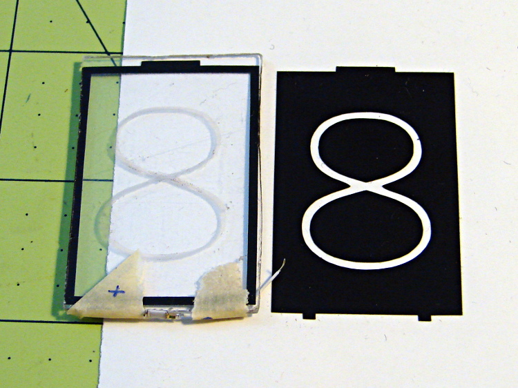
Crude edge-lit acrylic panel vs vinyl stencil
The “engraved” digit on the left came from a vinyl mask similar to the one on the right, using fine sandpaper to rough up the acrylic surface. I deliberately started with a battered old CD case in order to prevent myself from getting too compulsive with neatness; as you’ll see, edge-lit acrylic reveals any surface imperfections, so cleanliness is important.
The black border could be a light-shield gasket around the outer edge of the display panel to reduce glare from the edges. This might be more important for laser-cut pieces with highly reflective edges or for milled pieces with diffuse edges; there’s no way to tell without actually building one to see. I simply bandsawed the sheet around the edges of the mask, then filed off the larger chunks: the edges are very, very rough, indeed.
There doesn’t seem to be an easy way to stash the Inkscape SVG file on WordPress.
I solder-blobbed some wire-wrap wire, a 1206 SMD resistor, and a 0603 LED together:
Crude 0603 SMD LED lashup
The 0603 SMD LED fits neatly along the edge of the sheet:
0603 SMD on CD case edge
A 3rd hand holds it upright on the bench over the LED lashup:
Edge-lit acrylic – front layout
It looks marginally better with the lights out, but you can see all the scratches:
Edge-lit acrylic – front detail
The hot spot at the bottom of the digit isn’t nearly that awful in person.
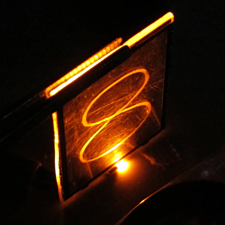
A top view shows the glowing edges, plus the nuclear glow from the LED:
Edge-lit acrylic – top view
A touch of soft focus, plus moving the LED under a tab location, helps a bit:
Edge-lit acrylic – front soft focus
You’d want two LEDs per digit and maybe one at the top, but that’s in the nature of fine tuning.
All in all, I like how it looks. Getting from this crud to a workable display will require far more effort than I can devote to it right now…
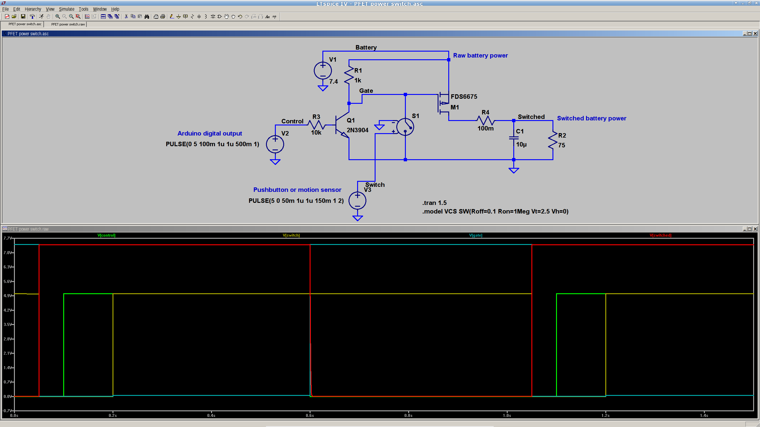
This is a simulation showing that a p-channel power MOSFET should work fine as a battery cutoff / switch for the bike taillight (clicky for many more dots):
P-MOSFET power switch
The general idea is to have a pushbutton or vibration sensor turn on the power, whereupon the Arduino wakes up and activates an output pin that holds the power on. When it’s time to shut down, the Arduino turns that output pin off, the power goes away, and everybody’s happy.
The MOSFET must be not only p-channel, but also have a logic-level gate, which is a rare and precious combination among cheap surplus MOSFETs. I’m hoping those FDS6675 MOSFETs work better than their package looks.
The capacitor and resistor over on the right simulate a reasonable load.
The voltage-controlled switch in the middle represents the vibration sensor, which is either shorted or open as determined by the voltage source at the bottom. There doesn’t seem to be any other Spice-ish way to do that.
The Arduino output, simulated by another voltage source drives the NPN transistor, which isolates the output pin from the 7.4 V (up to maybe 8.5 V when fully charged) Li-ion battery. It also isolates it from the switch, which would otherwise yank the output pin to ground if you pushed the button when the power was already on.
You’d want a few more pullup and pulldown resistors to ensure things stay where they’re put while the lights are out. I’d want to measure an actual vibration sensor; it may require a pulse stretcher to ensure the Arduino has enough time to wake up and smell the electrons.
Measured from the Official PCB Layout, with the board origin at the lower-left corner of the PCB, down there by the D9 pin, in mils (0.001 inch):
D9 = (50,50)
D10 = (650,50)
A5 = (535,805)
A4 = (535,705)
A7 = (535,393)
A6 = (535,293)
FTDI header = (100,1250) to (600,1250)
Reset button = (350,105)
D13 LED = (540,100)
PWR LED = (350,850)
Upper fiducial = (160,1140)
Lower fiducial = (490,100)
Subtract 50 mils from each of those coordinates to put the origin at the middle of the D9 pin, which may be more useful. Doing that in inches produces:
D9 = (0.000,0.000)
D10 = (0.600,0.000)
A5 = (0.485,0.755)
A4 = (0.485,0.655)
A7 = (0.485,0.343)
A6 = (0.485,0.243)
FTDI header = (0.050,1.200) to (0.550,1.200)
Reset button = (0.300,0.055)
D13 LED = (0.490,0.050)
PWR LED = (0.300,0.800)
Upper fiducial = (0.110,1.090)
Lower fiducial = (0.440,0.050)
Trust, but verify…
Yes, this is a knockoff PCB from the usual eBay vendor, not from Sparkfun. Contents may settle during shipment. Enlarged to show texture. Your mileage may vary. No warranty, either express or implied, no lie. Do not eat.
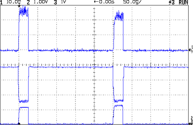
With that hardware in hand, a dab of firmware produces this result:
Hall Current Sense – 120 mA 25 ms 250 ms
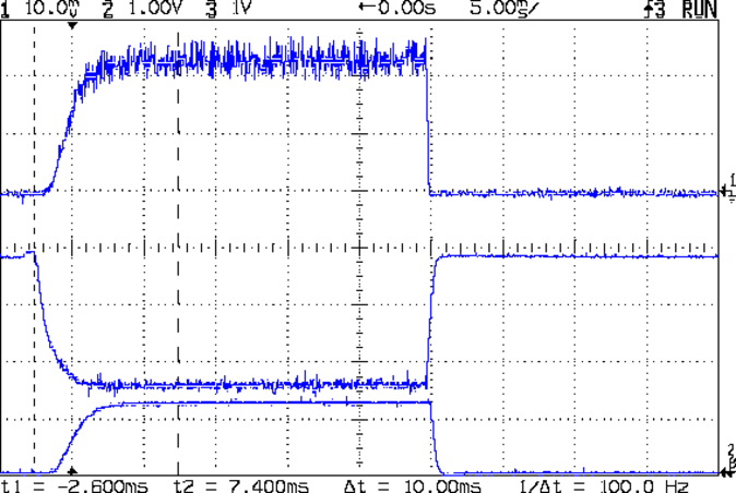
A detailed look at one pulse:
Hall Current Sense – 120 mA 25 ms 250 ms – detail
The top trace is the total LED current, nominally 120 mA, at 50 mA/div. The ripple (which is a nice triangle waveform at a faster sweep) comes from the 32 kHz PWM pulse train, despite passing through a 1 ms RC filter; the MOSFET runs in the linear region and makes a great amplifier.
The middle trace is the MOSFET drain voltage at 1 V/div. The on-state voltage runs around 1.6 V, so the LEDs see about 5.9 V at 120 mA, about what you’d expect, with the little bit of PWM ripple accounting for the current sawtooth in the top trace. The off-state voltage is only 3.8 V, because the LEDs soak up the rest; it’s about 1.2 V per LED.
The bottom trace is the current-sense amp output. The 1 nF cap in the op amp feedback loop rolls it off at 600 Hz, so there’s not much ripple at all in there. That goes directly to the Arduino’s ADC, where it’s further averaged over 10 samples.The LEDs take a couple of milliseconds to get up to full intensity, but it’s much faster than an incandescent filament: this thing blinks rather than flashes.
The current in each LED string runs from about 15 mA to 25 mA, with all the “old” LEDs at the low end and the “new” LED strings at the high end. Using unsorted LEDs from the same batch will probably be OK, although I’ll measure them just to see what they’re like.
The LEDs dissipate 700 mW and the MOSFET wastes 192 mW, so the efficiency is around 79%. Not too shabby for a linear regulator and it only gets better as the battery discharges. The toroid winding burns maybe 300 μW, so it’s not in the running; to be fair, a 1 Ω sense resistor would account for only 14 mW, but it would drop 120 mV instead of 3 mV, which is what matters more when the battery voltage drops.
That’s during the pulse, which should have a duty cycle under 25% or so, which means 175 mW and 48 mW on the average. Obviously, no heatsinks needed: each LED runs at 7 mW average under those conditions.
The firmware steps the gate voltage by the smallest possible increment, about 20 mV = 5 V / 256. The feedback loop adjusts the gate voltage in single steps to avoid goosing the LEDs with too much current; a binary search wouldn’t work very well at all. I think it’d be a good idea to build a table of transconductance (gate voltage to LED current) by ramping the gate voltage during startup, then fine-tune the coefficients during each pulse.
The console log tells the tale:
Hall effect Current Regulator
Ed Nisley - KE4ZNU - August 2013
Given Vcc: 5010 mV
Given VBatt divider ratio: 0.500
Bandgap reference voltage: 1105 mV
Battery voltage: 7551 mV
Nulling Hall sensor offset: 0 PWM
Final Hall sensor offset: 209 PWM
Gate voltage: 1947 mV  LED Current: 5 mA
Gate voltage: 1966 mV  LED Current: 6 mA
Gate voltage: 1986 mV  LED Current: 6 mA
Gate voltage: 2005 mV  LED Current: 7 mA
Gate voltage: 2025 mV  LED Current: 8 mA
Gate voltage: 2040 mV  LED Current: 8 mA
Gate voltage: 2064 mV  LED Current: 10 mA
Gate voltage: 2084 mV  LED Current: 11 mA
Gate voltage: 2103 mV  LED Current: 13 mA
Gate voltage: 2123 mV  LED Current: 14 mA
Gate voltage: 2142 mV  LED Current: 17 mA
Gate voltage: 2162 mV  LED Current: 19 mA
Gate voltage: 2177 mV  LED Current: 22 mA
Gate voltage: 2201 mV  LED Current: 25 mA
Gate voltage: 2221 mV  LED Current: 29 mA
Gate voltage: 2240 mV  LED Current: 33 mA
Gate voltage: 2255 mV  LED Current: 38 mA
Gate voltage: 2275 mV  LED Current: 44 mA
Gate voltage: 2294 mV  LED Current: 49 mA
Gate voltage: 2314 mV  LED Current: 56 mA
Gate voltage: 2333 mV  LED Current: 63 mA
Gate voltage: 2353 mV  LED Current: 70 mA
Gate voltage: 2372 mV  LED Current: 79 mA
Gate voltage: 2392 mV  LED Current: 89 mA
Gate voltage: 2412 mV  LED Current: 99 mA
Gate voltage: 2431 mV  LED Current: 110 mA
Gate voltage: 2451 mV  LED Current: 122 mA
Gate voltage: 2431 mV  LED Current: 110 mA
Gate voltage: 2451 mV  LED Current: 121 mA
Gate voltage: 2431 mV  LED Current: 110 mA
Gate voltage: 2451 mV  LED Current: 122 mA
Gate voltage: 2431 mV  LED Current: 110 mA
Gate voltage: 2451 mV  LED Current: 121 mA
The current feedback tweaks the gate voltage by one PWM increment on each loop, so the LED current pulses alternate between 110 and 122 mA when the loop finally reaches the setpoint. This doesn’t make any practical difference, as each LED string’s current varies by a few mA, at most, but maybe there should be a deadband of a bit more than ±1/2 PWM increment around the actual current.
The Arduino source code:
// LED Curve Tracer
// Ed Nisley - KE4ANU - August 2013

#include <stdio.h>

//----------
// Pin assignments

const byte PIN_READ_VBATT = 0;		// AI - battery voltage from divider
const byte PIN_READ_CURRENT = 1;	// AI - current sense amp
const byte PIN_READ_VGATE = 2;		// AI - actual gate voltage
const byte PIN_READ_HALL = 3;		// AI - raw Hall sensor voltage

const byte PIN_SET_BIAS = 11;		// PWM - VCC/2 bias voltage
const byte PIN_SET_VGATE = 3;		// PWM - MOSFET gate voltage

const byte PIN_HEARTBEAT = 13;		// DO - Arduino LED
const byte PIN_SYNC = 2;			// DO - scope sync output

//----------
// Constants

const float MaxLEDCurrent = 0.120;		// maximum LED current

const float Vcc = 5.01; 				// Arduino supply -- must be measured!

const float VBattRatio = 3.03/6.05;		// measured division ratio for battery divider

const float VStep = Vcc/256;			// minimum PWM voltage increment = 5 V / 256

const float IGain = 0.100;				// Hall sense voltage to LED current

const byte PWM_Settle = 10;				// PWM settling time ms

// Timer prescaler = 1:1 for 32 kHz PWM
#define TCCRxB 0x01

#define MK_UL(fl,sc) ((unsigned long)((fl)*(sc)))
#define MK_U(fl,sc) ((unsigned int)((fl)*(sc)))
#define MK_I(fl,sc) ((int)((fl)*(sc)))

//----------
// Globals

float AVRef1V1;					// 1.1 V bandgap reference - calculated from Vcc

float VBatt;					// battery voltage - calculated from divider
float VGateSense;				// actual gate voltage - measured after PWM filter
float ILEDSense;				// LED current from Hall effect sensor

float VGateDrive;				// gate drive voltage

byte PWMHallOffset;				// zero-field Hall effect sensor bias

long unsigned long MillisNow, MillisThen;	// sampled millis() value

//-- Read AI channel
//      averages several readings to improve noise performance
//		returns value in volts assuming known VCC ref voltage

#define NUM_T_SAMPLES    10

float ReadAI(byte PinNum) {

  word RawAverage;

  digitalWrite(PIN_SYNC,HIGH);					// scope sync

  RawAverage = (word)analogRead(PinNum);		// prime the averaging pump

  for (int i=2; i <= NUM_T_SAMPLES; i++) {
    RawAverage += (word)analogRead(PinNum);
  }

  digitalWrite(PIN_SYNC,LOW);

  RawAverage /= NUM_T_SAMPLES;

  return Vcc * (float)RawAverage / 1024.0;

}

//-- Set PWM output

void SetPWMVoltage(byte PinNum,float PWMVolt) {

byte PWM;

  PWM = constrain((byte)(255.0 * PWMVolt / Vcc),0,255);

  analogWrite(PinNum,PWM);
  delay(PWM_Settle);

}

//-- compute actual 1.1 V bandgap reference based on known VCC = AVcc (more or less)
//		adapted from http://code.google.com/p/tinkerit/wiki/SecretVoltmeter

float ReadBandGap(void) {

  word ADCBits;
  float VBandGap;

  ADMUX = _BV(REFS0) | _BV(MUX3) | _BV(MUX2) | _BV(MUX1);	// select 1.1 V input
  delay(2); // Wait for Vref to settle

  ADCSRA |= _BV(ADSC);										// Convert
  while (bit_is_set(ADCSRA,ADSC));

  ADCBits = ADCL;
  ADCBits |= ADCH<<8;

  VBandGap = Vcc * (float)ADCBits / 1024.0;
  return VBandGap;
}

//-- Helper routine for printf()

int s_putc(char c, FILE *t) {
  Serial.write(c);
}

//------------------
// Set things up

void setup() {

float AVRef1V1;

  pinMode(PIN_HEARTBEAT,OUTPUT);
  digitalWrite(PIN_HEARTBEAT,LOW);	// show we arrived

  pinMode(PIN_SYNC,OUTPUT);
  digitalWrite(PIN_SYNC,LOW);		// show we arrived

  TCCR1B = TCCRxB;					// set frequency for PWM 9 & 10
  TCCR2B = TCCRxB;					// set frequency for PWM 3 & 11

  analogWrite(PIN_SET_VGATE,0);		// force gate voltage = 0

  Serial.begin(57600);
  fdevopen(&s_putc,0);				// set up serial output for printf()

  printf("Hall effect Current Regulator\r\nEd Nisley - KE4ZNU - August 2013\r\n");

  printf("Given Vcc: %d mV\r\n",MK_I(Vcc,1000.0));
  printf("Given VBatt divider ratio: 0.%d\r\n",MK_I(VBattRatio,1000.0));

  AVRef1V1 = ReadBandGap();			// compute actual bandgap reference voltage
  printf("Bandgap reference voltage: %d mV\r\n",MK_I(AVRef1V1,1000.0));

  VBatt = ReadAI(PIN_READ_VBATT) / VBattRatio;
  printf("Battery voltage: %d mV\r\n",MK_I(VBatt,1000.0));

  SetPWMVoltage(PIN_SET_VGATE,0.0);		// zero LED current
  PWMHallOffset = 0;
  analogWrite(PIN_SET_BIAS,PWMHallOffset);
  printf("Nulling Hall sensor offset: %d PWM\r\n",PWMHallOffset);

  do {
	ILEDSense = IGain * ReadAI(PIN_READ_CURRENT);
//	printf("Current Sense: %d mA - ",MK_I(ILEDSense,1000.0));
	if (ILEDSense > 0.005) {
		PWMHallOffset += 1;
		analogWrite(PIN_SET_BIAS,PWMHallOffset);
        delay(PWM_Settle);
//		printf("Step offset: %d PWM\r\n",PWMHallOffset);
	}
  } while (ILEDSense > 0.005);
  printf("Final Hall sensor offset: %d PWM\r\n",PWMHallOffset);

  VGateDrive = 2.0;					// reasonable starting point

  MillisThen = millis();
}

//------------------
// Run the test loop

void loop() {

	if ((millis() - MillisThen) > 250) {
		MillisThen = millis();

		if (ILEDSense < MaxLEDCurrent) {
			VGateDrive += VStep;
		}
		else if (ILEDSense > MaxLEDCurrent) {
			VGateDrive -= VStep;
		}

		SetPWMVoltage(PIN_SET_VGATE,VGateDrive);

		VGateSense = ReadAI(PIN_READ_VGATE);
		printf("Gate voltage: %d mV  ",MK_I(VGateSense,1000.0));

		ILEDSense = IGain * ReadAI(PIN_READ_CURRENT);
		printf("LED Current: %d mA\r\n",MK_I(ILEDSense,1000.0));

		delay(50 - PWM_Settle - 3);
		SetPWMVoltage(PIN_SET_VGATE,0.0);

		digitalWrite(PIN_HEARTBEAT,!digitalRead(PIN_HEARTBEAT));
		digitalWrite(PIN_HEARTBEAT,!digitalRead(PIN_HEARTBEAT));
	}
}