Ed Nisley's Blog: Shop notes, electronics, firmware, machinery, 3D printing, laser cuttery, and curiosities. Contents: 100% human thinking, 0% AI slop.
Given that the GX270 case has a power pushbutton on the front panel, it seemed only reasonable to let it control the ATX power supply just like it used to. Most of the parts clumped in front of the panel’s ribbon cable handle that logic:
Low Voltage Interface Board – detail
The pushbutton on the far left parallels the front-panel button so I don’t have to reach around the box just to turn it on.
The schematic shows the relevant bits:
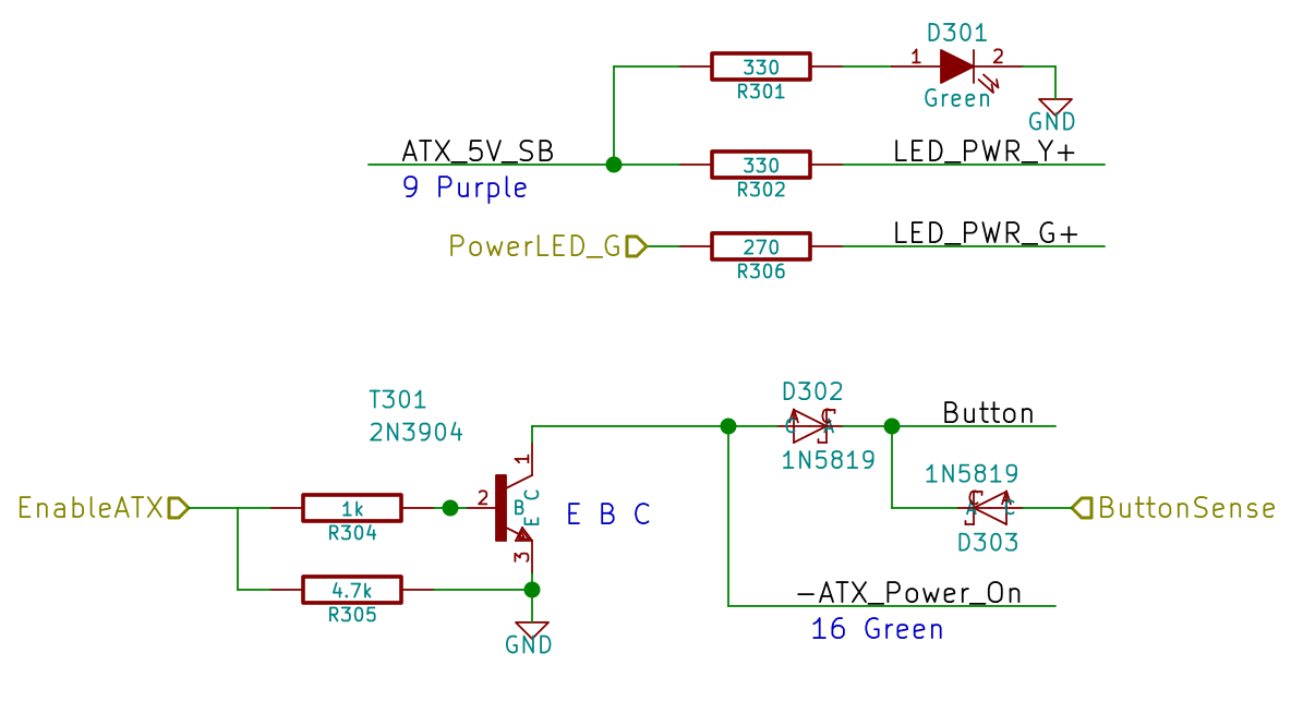
LV Power Interface – Power Button
The ATX +5 V Standby output remains turned on all the time, so I wired that to the power button’s yellow LED, to show that the plug is in the wall.
The pushbutton pulls the ATX Power_On line down, which turns on the supply outputs, which fires up the Arduino, which turns on the transistor, which holds the Power_On line down. D302 isolates the transistor from the button, so the code can sense the button’s on/off state with the power on. D303 isolates the Power_On line from the sense input to prevent the pullup on the Power_On line from back-powering the Arduino through its input protection diodes when the power is off.
The Arduino code starts by arranging the I/O states, turning the transistor on, pulsing the green power LED until until the button releases, then leaving the green LED on:
	pinMode(PIN_PWR_G,OUTPUT);
	digitalWrite(PIN_PWR_G,HIGH);				// visible on front panel

	pinMode(PIN_ENABLE_ATX,OUTPUT);				// hold ATX power supply on
	digitalWrite(PIN_ENABLE_ATX,HIGH);

	pinMode(PIN_ENABLE_AC,OUTPUT);				// turn on AC power
	digitalWrite(PIN_ENABLE_AC,HIGH);

	pinMode(PIN_BUTTON_SENSE,INPUT_PULLUP);		// wait for power button release
	while (LOW == digitalRead(PIN_BUTTON_SENSE)) {
		delay(50);
		TogglePin(PIN_PWR_G);					// show we have control
	}
	digitalWrite(PIN_PWR_G,HIGH);
Every time around the main loop, this chunk of code checks the button input:
	if (LOW == digitalRead(PIN_BUTTON_SENSE)) {
		printf("Shutting down!\r\n");
		digitalWrite(PIN_ENABLE_AC,LOW);
		digitalWrite(PIN_ENABLE_ATX,LOW);
		while(true) {
			delay(20);
			TogglePin(PIN_PWR_G);				// show we have shut down
		}
	}
The never-ending loop blinks the green LED until the power goes down, which happens when the button releases. That terminates the loop with extreme prejudice., which is the difference between embedded programming and high-falutin’ Webbish stuff.
That polycarbonate slab holds most of the pieces in place, with the rest on the prototype board to the left of the monster heatsink:
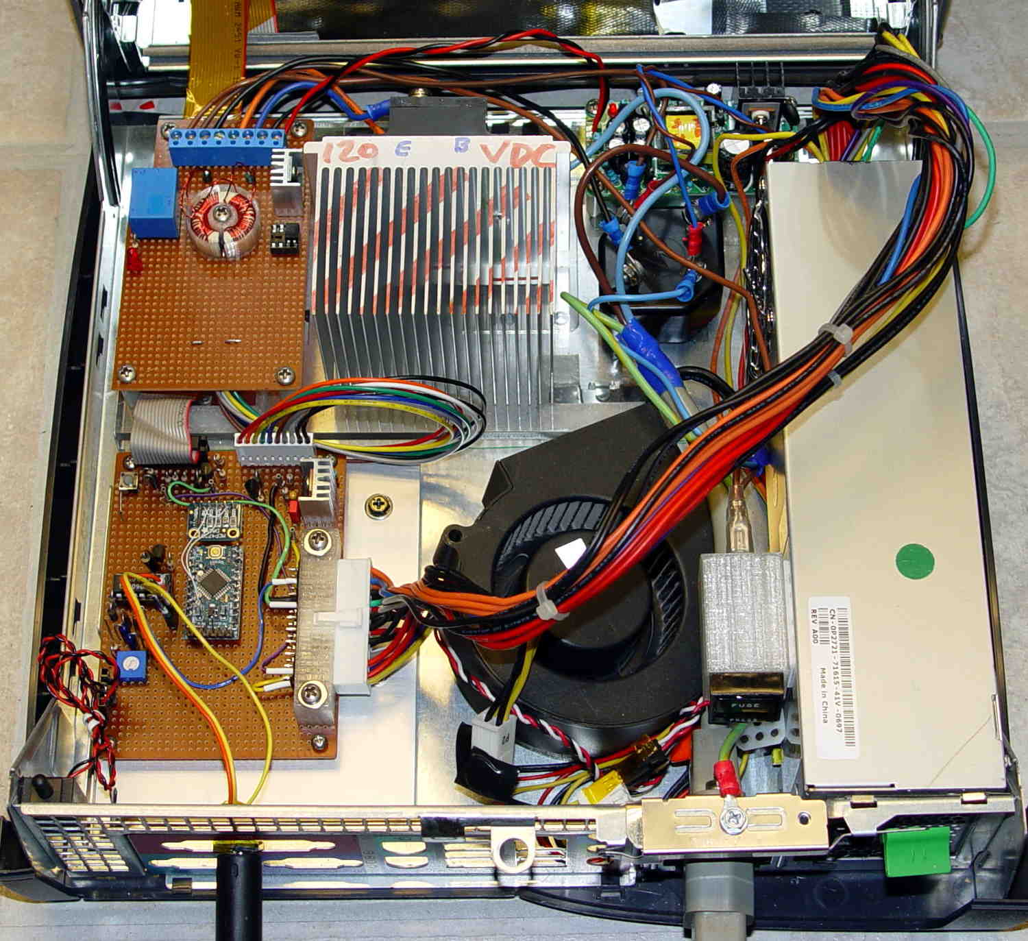
Model 158 Controller – Interior Overview
That bulky wire harness got bent out of the way for the photo; normally, it’s jammed down beside the ATX power supply and over the blower.
The AC Interface circuitry looks like this:
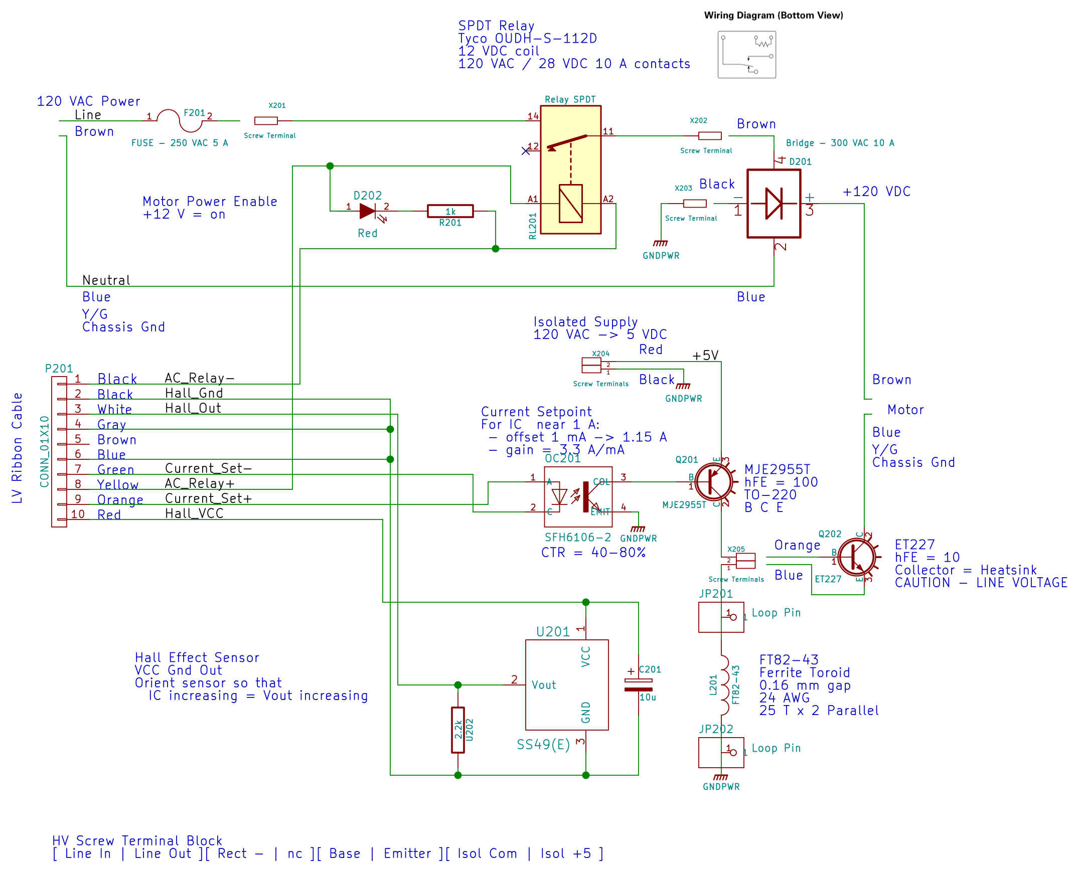
AC Power Interface
The relay on the top disconnects the AC line from the circuitry when the clamshell case opens.
The key hardware spreads neatly across the middle: the optoisolator, a 2955 PNP power transistor in a TO-220 case on a heatsink as a current amplifier, and the ET227 controlling the motor current. The gain of that mess depends strongly on the transistor temperatures, so there’s not much point in calibrating it. More on that later.
Down at the bottom of the schematic is the slit toroid and knockoff SS49(E) Hall effect sensor that senses the actual motor current.
A closer look at that board:
HV Interface board – detail
The board in the bottom left corner of the overview picture holds the Arduino Pro Mini that runs the whole show (so far, anyway), along with various & sundry analog circuitry that I’ll write up in a bit.
Conspicuous by their absence:
Motor speed sensing
Shaft position sensing
Power to the LED strip lights
Permanent mount for the pedal cable socket
Now I can make measurements without killing myself…
For some reason, WordPress chokes when uploading the starting shape as a PNG file, so here it is as a JPG with a black border replacing the original transparency:
gel_shape
With the gel highlight:
gel_highlight
Adding a border:
gel_border
Adding text, shadow, and background:
gel_button
Adding the drop shadow may increase the image size ever so slightly, so the -repage 0x0+7+7 operation may require resetting the exact image size.
The smaller buttons came directly from The GIMP, with full-frontal manual control over everything. Obviously, that doesn’t scale well for many buttons that should all look pretty much the same, because you want to get your fingers out of the loop.
But, obviously, when you do this on a mass scale, you want better control over the colors and text and suchlike; that’s in the nature of fine tuning when it’s needed.
I’m not entirely convinced I want gel-flavored buttons, but it was a fun exercise.
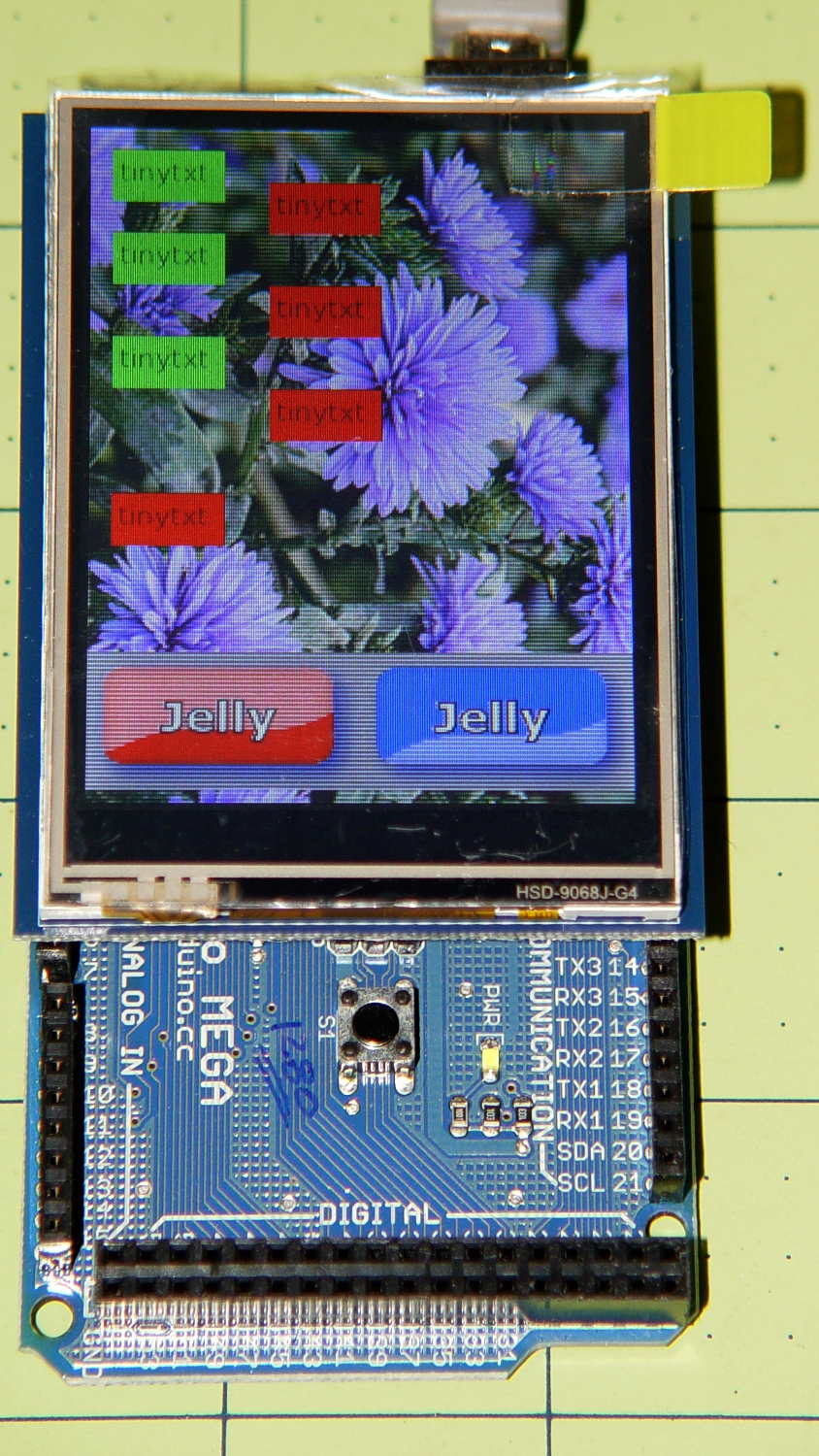
The Adafruit 2.8 inch TFT Touch Shield for Arduino v2 seems just about ideal for a small control panel, such as one might use with a modified sewing machine. All you need is a few on-screen buttons, a few status display, and a bit of Arduino love: what more could one ask?
So I gimmicked up some small buttons with GIMP, made two large buttons with ImageMagick, and lashed together some Arduino code based on the Adafruit demo:
Adafruit TFT display – timing demo
The picture doesn’t do justice to the display: it’s a nice piece of hardware that produces a crisp image. The moire patterns come from the interaction of TFT display pixels / camera pixels / image resizing.
It’s not obvious from the Adafruit description, but the display is inherently portrait-mode as shown. The (0,0) origin lies in the upper left corner, just over the DC power jack, and screen buffer updates proceed left-to-right, top-to-bottom from there.
The gotcha: even with the Arduino Mega’s hardware SPI, writing the full display requires nearly 4 seconds. Yeah, slow-scan TV in action. Writing the screen with a solid color requires several seconds.
After commenting out the serial tracing instructions from the Adafruit demo and tweaking a few other things, these timings apply:
-------------
Writing background
Elapsed: 3687
Writing six buttons
Elapsed: 529
Overwriting six buttons
Elapsed: 531
Rewriting buttons 10 times
Elapsed: 1767
Overwriting 2 large buttons
Elapsed: 1718
The button images come from BMP files on a MicroSD card and 8 KB of RAM won’t suffice for even a small button. Instead, the transfer loop buffers 20 pixels = 60 bytes from the card, writes them to the display, and iterates until it’s done.
Trust me on this: watching the buttons gradually change is depressing.
Yes, it could work as a control panel for the sewing machine, but it doesn’t have nearly the pep we’ve come to expect from touch-screen gadgetry. On the other paw, Arduinos are 8-bit microcontrollers teleported from the mid-90s, when crappy 20×4 LCD panels were pretty much as good as it got.
The SPI hardware clock runs at half the oscillator frequency = 16 MHz/2 = 8 MHz = 125 ns/bit. Clocking a single byte thus requires 1 µs; even allowing that each pixel = 3 bytes = 6 SPI operations, there’s a lot of software overhead ripe for the chopping block. I’d be sorely tempted to write a pair of unrolled loops that read 20 pixels and write 20 pixels with little more than a pointer increment & status spin between successive SPI transfers.
It’ll make hotshot C++ programmers flinch, but splicing all that into a single routine, throwing out all the clipping and error checking, and just getting it done might push the times down around 20 µs/pixel. Admittedly, that’s barely twice as fast, but should be less depressing.
However, even with all that effort, the time required to update the screen will clobber the motor control. You can’t devote a big fraction of a second to rewriting a button at the same time you’re monitoring the pedal position, measuring the motor speed, and updating the control voltage. That’s the same problem that makes Arduino microcontrollers inadequate for contemporary 3D printers: beyond a certain point, the hardware is fighting your efforts, not helping you get things done.
A reasonable workaround: no screen updates while the motor turns, because you shouldn’t have any hands free while you’re sewing.
The Arduino source code, hacked from the Adafruit demo:
// 2.8 inch TFT display exercise
// Crudely hacked from Adafruit demo code: spitftbitmap.ino
// 2014-07-03 Ed Nisley KE4ZNU

/***************************************************
  This is our Bitmap drawing example for the Adafruit ILI9341 Breakout and Shield
  ----> http://www.adafruit.com/products/1651

  Check out the links above for our tutorials and wiring diagrams
  These displays use SPI to communicate, 4 or 5 pins are required to
  interface (RST is optional)
  Adafruit invests time and resources providing this open source code,
  please support Adafruit and open-source hardware by purchasing
  products from Adafruit!

  Written by Limor Fried/Ladyada for Adafruit Industries.
  MIT license, all text above must be included in any redistribution
 ****************************************************/

#include <Adafruit_GFX.h>    // Core graphics library
#include "Adafruit_ILI9341.h" // Hardware-specific library
#include <SPI.h>
#include <SD.h>

#define TFT_DC 9
#define TFT_CS 10
Adafruit_ILI9341 tft = Adafruit_ILI9341(TFT_CS, TFT_DC);

#define SD_CS 4

unsigned long MillisNow, MillisThen;

void setup(void) {
  Serial.begin(115200);

  tft.begin();
  tft.fillScreen(ILI9341_BLACK);

  Serial.print(F("Initializing SD card..."));
  if (!SD.begin(SD_CS)) {
    Serial.println(F("failed!"));
  }
  Serial.println(F("OK!"));

}

void loop() {
  Serial.println(F("--------------"));
  Serial.println(F("Writing background"));
  MillisThen = millis();

  bmpDraw("Test1.bmp", 0, 0);

  MillisNow = millis();
  Serial.print(F("" Elapsed: ""));
  Serial.println(MillisNow - MillisThen);

  Serial.println(F("Writing 6 small buttons"));
  MillisThen = millis();

  bmpDraw("Red50x25.bmp",10,10);
  bmpDraw("Red50x25.bmp",10,50);
  bmpDraw("Red50x25.bmp",10,100);

  bmpDraw("Grn50x25.bmp",80,25);
  bmpDraw("Grn50x25.bmp",80,75);
  bmpDraw("Grn50x25.bmp",80,125);

  MillisNow = millis();
  Serial.print(F("" Elapsed: ""));
  Serial.println(MillisNow - MillisThen);

  Serial.println(F("Overwriting 6 small buttons"));
  MillisThen = millis();

  bmpDraw("Grn50x25.bmp",10,10);
  bmpDraw("Grn50x25.bmp",10,50);
  bmpDraw("Grn50x25.bmp",10,100);

  bmpDraw("Red50x25.bmp",80,25);
  bmpDraw("Red50x25.bmp",80,75);
  bmpDraw("Red50x25.bmp",80,125);

  MillisNow = millis();
  Serial.print(F("" Elapsed: ""));
  Serial.println(MillisNow - MillisThen);

  Serial.println(F("Writing small button 10x2 times"));
  MillisThen = millis();

  for (byte i=0; i<10; i++) {
    bmpDraw("Grn50x25.bmp",10,175);
    bmpDraw("Red50x25.bmp",10,175);
  }

  MillisNow = millis();
  Serial.print(F("" Elapsed: ""));
  Serial.println(MillisNow - MillisThen);

  Serial.println(F("Overwriting 2 large buttons"));
  MillisThen = millis();

  bmpDraw("GelDn.bmp",0,250);
  bmpDraw("GelUp.bmp",0,250);

  bmpDraw("GelUp.bmp",120,250);
  bmpDraw("GelDn.bmp",120,250);

  MillisNow = millis();
  Serial.print(F("" Elapsed: ""));
  Serial.println(MillisNow - MillisThen);

}

// This function opens a Windows Bitmap (BMP) file and
// displays it at the given coordinates.  It's sped up
// by reading many pixels worth of data at a time
// (rather than pixel by pixel).  Increasing the buffer
// size takes more of the Arduino's precious RAM but
// makes loading a little faster.  20 pixels seems a
// good balance.

#define BUFFPIXEL 20

void bmpDraw(char *filename, uint8_t x, uint16_t y) {

  File     bmpFile;
  int      bmpWidth, bmpHeight;   // W+H in pixels
  uint8_t  bmpDepth;              // Bit depth (currently must be 24)
  uint32_t bmpImageoffset;        // Start of image data in file
  uint32_t rowSize;               // Not always = bmpWidth; may have padding
  uint8_t  sdbuffer[3*BUFFPIXEL]; // pixel buffer (R+G+B per pixel)
  uint8_t  buffidx = sizeof(sdbuffer); // Current position in sdbuffer
  boolean  goodBmp = false;       // Set to true on valid header parse
  boolean  flip    = true;        // BMP is stored bottom-to-top
  int      w, h, row, col;
  uint8_t  r, g, b;
  uint32_t pos = 0, startTime = millis();

  if((x >= tft.width()) || (y >= tft.height())) return;

//  Serial.println();
//  Serial.print(F("Loading image '"));
//  Serial.print(filename);
//  Serial.println('\'');

  // Open requested file on SD card
  if ((bmpFile = SD.open(filename)) == NULL) {
//    Serial.print(F("File not found"));
    return;
  }

  // Parse BMP header
  if(read16(bmpFile) == 0x4D42) { // BMP signature
//    Serial.print(F("File size: "));
//	Serial.println(read32(bmpFile));
	read32(bmpFile);
    (void)read32(bmpFile); // Read & ignore creator bytes
    bmpImageoffset = read32(bmpFile); // Start of image data
//    Serial.print(F("Image Offset: ")); Serial.println(bmpImageoffset, DEC);
    // Read DIB header
//    Serial.print(F("Header size: "));
//	Serial.println(read32(bmpFile));
	read32(bmpFile);
    bmpWidth  = read32(bmpFile);
    bmpHeight = read32(bmpFile);
    if(read16(bmpFile) == 1) { // # planes -- must be '1'
      bmpDepth = read16(bmpFile); // bits per pixel
//      Serial.print(F("Bit Depth: ")); Serial.println(bmpDepth);
      if((bmpDepth == 24) && (read32(bmpFile) == 0)) { // 0 = uncompressed

        goodBmp = true; // Supported BMP format -- proceed!
//        Serial.print(F("Image size: "));
//        Serial.print(bmpWidth);
//        Serial.print('x');
//        Serial.println(bmpHeight);

        // BMP rows are padded (if needed) to 4-byte boundary
        rowSize = (bmpWidth * 3 + 3) & ~3;

        // If bmpHeight is negative, image is in top-down order.
        // This is not canon but has been observed in the wild.
        if(bmpHeight < 0) {
          bmpHeight = -bmpHeight;
          flip      = false;
        }

        // Crop area to be loaded
        w = bmpWidth;
        h = bmpHeight;
        if((x+w-1) >= tft.width())  w = tft.width()  - x;
        if((y+h-1) >= tft.height()) h = tft.height() - y;

        // Set TFT address window to clipped image bounds
        tft.setAddrWindow(x, y, x+w-1, y+h-1);

        for (row=0; row<h; row++) { // For each scanline...

          // Seek to start of scan line.  It might seem labor-
          // intensive to be doing this on every line, but this
          // method covers a lot of gritty details like cropping
          // and scanline padding.  Also, the seek only takes
          // place if the file position actually needs to change
          // (avoids a lot of cluster math in SD library).
          if(flip) // Bitmap is stored bottom-to-top order (normal BMP)
            pos = bmpImageoffset + (bmpHeight - 1 - row) * rowSize;
          else     // Bitmap is stored top-to-bottom
            pos = bmpImageoffset + row * rowSize;
          if(bmpFile.position() != pos) { // Need seek?
            bmpFile.seek(pos);
            buffidx = sizeof(sdbuffer); // Force buffer reload
          }

          for (col=0; col<w; col++) { // For each pixel...
            // Time to read more pixel data?
            if (buffidx >= sizeof(sdbuffer)) { // Indeed
              bmpFile.read(sdbuffer, sizeof(sdbuffer));
              buffidx = 0; // Set index to beginning
            }

            // Convert pixel from BMP to TFT format, push to display
            b = sdbuffer[buffidx++];
            g = sdbuffer[buffidx++];
            r = sdbuffer[buffidx++];
            tft.pushColor(tft.color565(r,g,b));
          } // end pixel
        } // end scanline
//        Serial.print(F("Loaded in "));
//        Serial.print(millis() - startTime);
//        Serial.println("" ms"");
      } // end goodBmp
    }
  }

  bmpFile.close();
  if(!goodBmp) Serial.println(F("BMP format not recognized."));
}

// These read 16- and 32-bit types from the SD card file.
// BMP data is stored little-endian, Arduino is little-endian too.
// May need to reverse subscript order if porting elsewhere.

uint16_t read16(File &f) {
  uint16_t result;
  ((uint8_t *)&result)[0] = f.read(); // LSB
  ((uint8_t *)&result)[1] = f.read(); // MSB
  return result;
}

uint32_t read32(File &f) {
  uint32_t result;
  ((uint8_t *)&result)[0] = f.read(); // LSB
  ((uint8_t *)&result)[1] = f.read();
  ((uint8_t *)&result)[2] = f.read();
  ((uint8_t *)&result)[3] = f.read(); // MSB
  return result;
}
Last week I gave a class at Squidwrench that helped bootstrap folks from new-to-Arduino to won’t-blow-it-up, showing how the I/O pins work in digital and analog mode with a bit of hands-on experimentation:
Potentiometer – analog input
We also covered some setup, how the whole compiler thing works, and suchlike.
The parts kit contains a 10 kΩ pot (with detents!), a green LED (with resistor!), and a jumper that serves as both a switch and a short antenna for an input without a pullup. They’re all terminated in header pins with heatstink tubing for strain relief.
The ZIP file with all the source code (ArduinoIOIntro-2014-06.zip.odt) masquerades as an OpenDocument text file, because WordPress prohibits ZIP files. Just rename it to remove the ODT suffix, unzip it, and there you are. It also includes the PDF, because none of the Arduino files have any comments at all…
Because the current control loop closes through the Arduino loop(), the code’s path length limits the bandwidth. Worse, the PWM filter imposes a delay while the DC value catches up with the new duty cycle. Here’s what that looks like:
LoopStatus ILED 50 mA div – 200 50 150 25 mA
The setpoint current for this pulse is 200 mA, ramping upward from 50 mA. It should have started from 25 mA, but the loop really wasn’t under control here.
The top trace goes low during the drain current measurement, which occurs just before the code nudges the gate drive by 1 PWM count to reduce the error between the setpoint and the measurement. A delay(1) after each PWM change, plus the inherent delay due to all the program statements, produces an update every 1.7 ms, more or less.
Even at that low rate, the current overshoots by 50 mA before the loop can tamp it down again. The current varies by 200 mA for 7 PWM counts, call it 30 mA per count at the high end, so overshooting by 50 mA comes with the territory. There’s just not a lot of resolution available.
The program reads each pulse duration and amplitude from an array-of-structs, so it’s a simple matter of software to save the gate drive voltage at the end of each pulse and restore it when that pulse comes around on the guitar again:
	if (millis() >= (EventStart + (unsigned long)Events[EventIndex].duration)) {
		Events[EventIndex].drive_a = VGateDriveA;						// save drive voltages
		Events[EventIndex].drive_b = VGateDriveB;

        if (++EventIndex > MAX_EVENT_INDEX)								// step to next event
		    EventIndex = 0;

		VGateDriveA = Events[EventIndex].drive_a;						// restore previous drives
		VGateDriveB = Events[EventIndex].drive_b;

		SetPWMVoltage(PIN_SET_VGATE_A,VGateDriveA);
		SetPWMVoltage(PIN_SET_VGATE_B,VGateDriveB);

		delay(PWM_Settle);

		digitalWrite(PIN_ENABLE_A,Events[EventIndex].en_a);				// enable gates for new state
		digitalWrite(PIN_ENABLE_B,Events[EventIndex].en_b);

        NeedHallNull = !(Events[EventIndex].en_a || Events[EventIndex].en_b);	// null sensor if all off

		EventStart = millis();                                          // record start time
	}
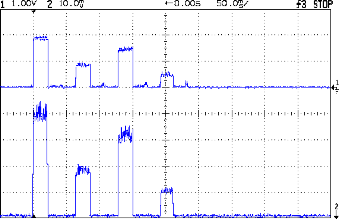
… which produces this happy result, with a different time scale to show all four pulses in the array:
I Sense Amp ILED 50 mA div – 200 100 150 50 mA
The top trace shows the current amp output that goes into the Arduino analog input and the bottom trace shows the MOSFET drain current. Notice those nice, crisp edges with a nearly complete lack of current adjustment.
The small bumps in the amp output just after the LED turns off happen while the the code nulls the Hall effect sensor offset. Whenever the LEDs turn off, the code nulls the sensor, which is probably excessive; it really doesn’t have much else to do, so why not?
This trickery doesn’t improve the loop bandwidth at all, because the code must still drag the current to meet each setpoint, but now that happens only when the pulse first appears. After a few blinks, the current stabilizes at the setpoint and the loop need handle only slight variations due to temperature or battery voltage changes.
Speaking of voltages:
VDS ILED 50 mA div – 200 100 150 50 mA
The top trace now shows the MOSFET drain voltage and the bottom still has the LED current. There’s only 650 mV of difference at the drain for currents of 50 mA and 200 mA through the LEDs, with about 1 V of headroom remaining at 200 mA.
The power supply delivers 7.4 V to the anode end of the LEDs, so they drop 6.3 V @ 200 mA and 5.7 V @ 50 mA. Some informal knob twiddling suggests that the MOSFET loses control authority at about 6.5 V, so, given that there’s not much energy in the battery below 7.0 V anyway, the program could limit the maximum current to 50 mA when the battery hits 7 V, regain 650 mV of headroom, and run at reduced brightness (and perhaps a different blink pattern) until the battery drops to 6.5 V, at which point the lights go out.
There’s more improvement to be had in the code, but those pulses look much better.
(If you’re keeping track, as I generally don’t, this is Post Number 2048: love those round numbers!)
The original 32 kHz PWM produced plenty of ripple in the LED current:
VG 1193 mV – ID 50 mA-div – 1 ms PWM filter
Using 64 kHz PWM requires putting the timers in Fast PWM Mode:
Timer 1: Mode 5 = Fast PWM, 8-bit resolution
Timer 2: Mode 3
The Arduino code that does the deed:
// Timer 1: PWM 9 PWM 10 - Hall offset
TCCR1A = B10000001; // Mode 5 = fast 8-bit PWM with TOP=FF
TCCR1B = B00001001; // ... WGM, 1:1 clock scale -> 64 kHz

// Timer 2: PWM3 PWM11 - MOSFET gate drive A, B
TCCR2A = B10100011; // Mode 3 = fast PWM with TOP=FF
TCCR2B = B00000001; // ... 1:1 clock scale -> 64 kHz

analogWrite(PIN_SET_VGATE_A,0); // force gate voltage = 0
analogWrite(PIN_SET_VGATE_B,0);
With that in hand, things look a lot better:
PWM Ripple – 64 kHz 200 mA
The oscilloscope scales aren’t the same and the PWM duty cycle isn’t quite the same, but the LED current ripple drops by a little more than the factor of two you’d expect.