Ed Nisley's Blog: Shop notes, electronics, firmware, machinery, 3D printing, laser cuttery, and curiosities. Contents: 100% human thinking, 0% AI slop.
The user community asked for toned-down buttons, in place of my rather garish color scheme. A bit of twiddling with the Hue parameter produced these buttons:
Kenmore 158 UI – Pastel Buttons
Which look pretty good in context:
Kenmore 158 UI – Pastel buttons
The Bash script, which includes Unicode characters that may confuse your browser:
The trick depends on specifying the colors with HSB, rather than RGB, so that the buttons in each row have the same hue and differ in saturation and brightness. The Imagemagick incantations look like this:
Disabled: hsb\(${HUE}%,50%,40%\)
Unselected: hsb\(${HUE}%,100%,70%\)
Selected: hsb\(${HUE}%,100%,100%\)
For whatever reason, the hue must be a percentage if the other parameters are also percentages. At least, I couldn’t figure out how to make a plain integer without a percent sign suffix work as a degree value for hue.
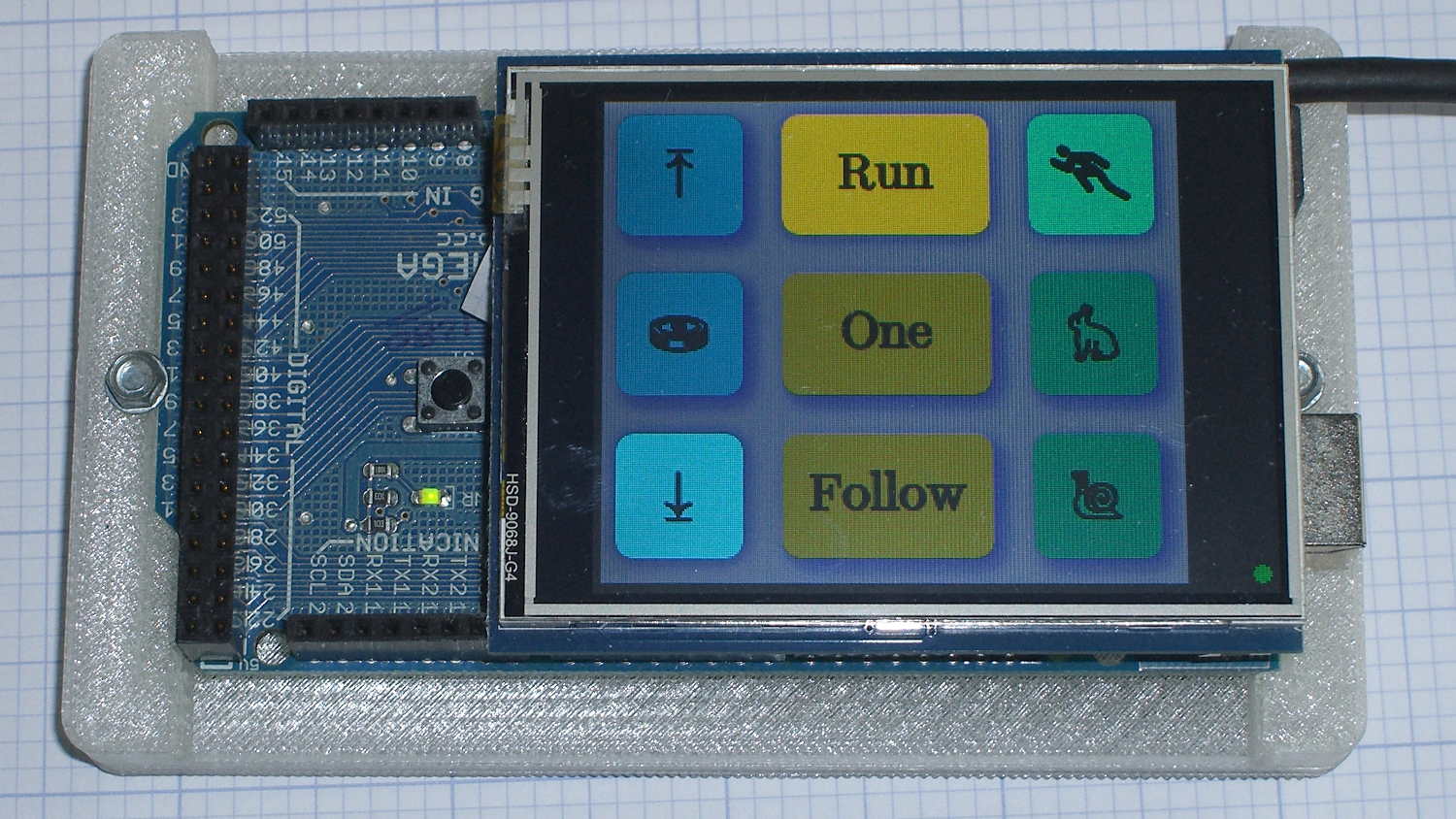
Anyhow, in real life they look pretty good and make the selected buttons much more obvious:
The LCD screen looks just like that; I blew out the contrast on the surroundings to provide some context. The green square on the left is the Arduino Mega’s power LED, the purple dot on the right is the heartbeat spot.
The new “needle stop anywhere” symbol (left middle) is the White Draughts Man Unicode character: ⛀ = U+26C0. We call them checkers here in the US, but it’s supposed to look like a bobbin, as you must disengage the handwheel clutch and stop the main shaft when filling a bobbin; the needle positioning code depends on the shaft position sensor.
Weirdly, Unicode has no glyphs for sewing, not even a spool of thread, although “Fish Cake With Swirl” (🍥 = U+1F365) came close. Your browser must have access to a font with deep Unicode support in order to see that one…
Given that I’m throwing all the balls in the air at once:
V4 hot end / filament drive
24 VDC motor / logic power supply
PETG filament
It seemed reasonable to start with the current Marlin firmware, rather than the MakerGear version from long ago. After all, when you file a bug report, the first question is whether it happens with the Latest Version.
Marlin has undergone a Great Refactoring that moved many of the constants around. I suppose I should set up a whole new Github repository, but there aren’t that many changes and I’ve gotten over my enthusiasm for forking projects.
Anyhow, just clone the Marlin repo and dig in.
In Marlin_main.cpp, turn on the Fan 1 output on Arduino pin 6 that drives the fans on the extruder and electronics box:
pinMode(6,OUTPUT);	// kickstart Makergear M2 extruder fan
digitalWrite(6,HIGH);
You could use the built-in extruder fan feature that turns on when the extruder temperature exceeds a specific limit. I may try that after everything else works; as it stands, this shows when the firmware gets up & running after a reset.
In Configuration_adv.h, lengthen the motor-off time and set the motor currents:
I missed the max & min position settings on the first pass (they’re new!), which matter because I put the origin in the middle of the platform, rather than the front-left corner. Marlin now clips coordinates outside that region, so the first thinwall calibration box only had lines in Quadrant 1…
case PD_RUN :
	if (PedalPosition > 5) {
		if (MotorDrive.State != RUNNING) {
			EnableMotor();
			MotorDrive.State = RUNNING;
		}

		BaseDAC.setVoltage(0x0fff,false);								// give it a solid pulse
		SampleCurrent(PIN_CURRENT_SENSE);								// sample over a half cycle
		if (DriveOnTime > CurrentSamplingTime) {
			delay(DriveOnTime - CurrentSamplingTime);
		}

// Pedal to the metal?
//   ... if so, stall here with motor drive fully on until the pedal releases

		while ((MotorDrive.SpeedRange == SPEED_HIGH) && (PedalPosition >= 100)) {
			PedalPosition = PedalPercent(ReadAI(PIN_PEDAL));
		}

		BaseDAC.setVoltage(0,false);									//  ... then turn it off

		delay(map(constrain(PedalPosition,0,PedalMaxClamp),
				0,100,
				DriveOffTime,0));
	}
	else {
		if (MotorDrive.State == RUNNING) {
			if (MotorSensor.RPM) {
				printf("Coast: %d\r\n",MotorSensor.RPM);
				delay(100);
			}
			else {
				printf("Parking ");
				ParkNeedle(MotorDrive.ParkPosition);
				MotorDrive.State = STOPPED;
				printf(" stopped\r\n");
			}
		}
	}
	break;
The magic happens in highlighted statement, which flips the sense of the pedal motion and linearly scales the result into a delay() value ranging from 120 ms (pedal barely pressed) down to 0 ms (pedal almost fully pressed). If the pedal is all the way down, then the preceding while() locks up until it’s released a bit, whereafter the delay will be nearly zero.
That sorta-kinda worked, but the user community said that the pedal response required pushing too hard for top speed: it should get faster, sooner. The problem came from the simplistic way I set the speed: it was inversely proportional to the position.
Plotting speed against pedal position shows the problem:
Speed vs pedal – period control
I figured the right approach was to make the speed vary linearly with the pedal position, so the trick was to plot the off-time delay vs. the actual speed:
Off-time delay vs speed – period control
The second-order equation bottles up a bunch of nonlinear things. Given that this was using the original code, I made the dubious assumption that more-or-less the same delay in the new code would produce more-or-less the same speed.
The new code discards the current-sampling routine that I was using to get a fixed delay (because I don’t need to know the current in pulse-drive mode), then used that time for the floating-point calculation required to find the off-time delay. That chunk of code took a bit of fiddling to get right:
case PD_RUN :
	if (PedalPosition > 5) {
		if (MotorDrive.State != RUNNING) {
			EnableMotor();
			MotorDrive.State = RUNNING;
		}

		BaseDAC.setVoltage(0x0fff,false);								// give it a solid pulse
		MillisOn = millis() + (unsigned long)DriveOnTime;

		TargetSpeed = (float)map(constrain(PedalPosition,0,PedalMaxClamp),
				0,100,
				0,700);						// quick and dirty 0 to 700 stitch/min range
		OffTime = (int)((1.94e-4*TargetSpeed - 0.286)*TargetSpeed + 106.0);
		OffTime = constrain(OffTime,0,120);								// clamp to reasonable range
		MillisOff = MillisOn + (unsigned long)OffTime;					// compute end of off time

		while (millis() <= MillisOn) {									// wait for end of pulse
			continue;
		}

		if ((PedalPosition >= 100) && (MotorDrive.SpeedRange == SPEED_HIGH)) {	// pedal down in full speed mode?
			printf("Full speed ... ");
			OffTime = 0;
			while (PedalPosition >= 100) {								//  ... full throttle!
				PedalPosition = PedalPercent(ReadAI(PIN_PEDAL));
			}
			BaseDAC.setVoltage(0,false);								//  pedal released, start coasting
			printf(" done\r\n");
		}
		else {															// pedal partially pressed
			BaseDAC.setVoltage(0,false);								// pulse done, turn motor off
			while (millis() <= MillisOff) {								// wait for end of off period
				continue;
			}
		}
	}
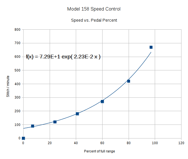
But the result looks as pretty as you could possibly expect:
Speed vs pedal – linearized speed control
The pedal still provides a soft-start transition from not moving to minimum speed, which remains an absolute requirement: having an abrupt transition to that straight line would be a Bad Thing. Fortunately, the nature of the magnet moving toward the Hall effect sensor gives you that for free.
Although we’re still evaluating the results, the user community seems happier…
Adjusting the output voltage vs. position for the sewing machine’s food pedal quickly revealed that the code shouldn’t depend on the actual ADC values. That’s blindingly obvious in hindsight, of course.
The maximum with the pedal in its overtravel region doesn’t change by much, because the Hall effect sensor output voltage saturates in a high magnetic field. I used a hardcoded word PedalMax = 870; which comes from 4.25 V at the ADC input.
On the low end, the sensor output can change by a few counts depending on small position changes, so I sampled the (presumably released) pedal output during the power-on reset:
	PedalMin = ReadAI(PIN_PEDAL);				// set minimum pedal input value
	printf("Set PedalMin: %u\r\n",PedalMin);
	PedalMaxClamp = 100;						// set upper speed limit
Given the complete ADC range, this function normalizes a value to the range [0,100], conveniently converting the pedal position into a percent of full scale:
int PedalPercent(word RawPos) {
int Clamped;

	Clamped = constrain(RawPos,PedalMin,PedalMax);
	return map(Clamped,PedalMin,PedalMax,0,100);
}
Graphing the normalized values against pedal position would have the same shape as the ADC values. All I’m doing is rescaling the Y axis to match the actual input limits.
The top of the main loop captures the pedal position:
Now, it’s easy to add a slight deadband that ensures the sewing machine doesn’t start when you give the pedal a harsh look; the deadband is now a percent of full travel, rather than a hard-coded ADC count or voltage.
For example, in needle-follows-pedal mode, you must press the pedal by more than 10% to start the stitch, slightly release it to finish the stitch, and then almost completely release it to proceed to the next stitch:
	case PD_FOLLOW:
		if (PedalPosition > 10) {
			printf("Pedal Follow\r\n");
			ParkNeedle(NS_DOWN);
			do {
				PedalPosition = PedalPercent(ReadAI(PIN_PEDAL));
			} while (PedalPosition > 10);
			ParkNeedle(NS_UP);
			do {
				PedalPosition = PedalPercent(ReadAI(PIN_PEDAL));
			} while (PedalPosition > 2);
		}
		break;
Adjusting percentages turns out to be much easier than fiddling with ADC values.
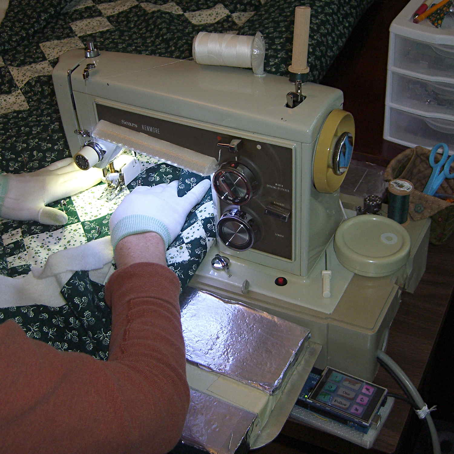
The Crash Test Dummy’s double-walled and somewhat crushed base turns out to be slightly larger front-to-back than the one on Mary’s original Kenmore 158 (which has a later serial number), but it still fits into the cutout in the insulating board we’re using in lieu of a Real Sewing Surface:
Early reports indicate that the pedal doesn’t feel quite right, with faster speeds requiring too much travel. Given that I worked hard to get more travel with slower transitions into that thing, differences shouldn’t come as any surprise, but … this will require some tweaking.
Now that the sewing machine motor controller receives commands from the UI (or typed in on a console), it must decode them. The “parser” doesn’t amount to much, because the commands consist of exactly two characters wrapped in square brackets. For simplicity, if the format doesn’t match or the command isn’t exactly right, the decoder simply tosses it on the floor and moves on:
void ParseCmd(char *pBuff) {

	if ((CmdBuffer[0] != '[') || (CmdBuffer[3] != ']')) {
		printf("** Bad cmd format: %s\r\n",CmdBuffer);
		return;
	}

	switch (CmdBuffer[1]) {
	case 'N':							// needle park position
		switch (CmdBuffer[2]) {
		case 'u':
			MotorDrive.ParkPosition = NS_UP;
//			ParkNeedle(NS_UP);
			break;
		case 'a':
			MotorDrive.ParkPosition = NS_NONE;
			break;
		case 'd':
			MotorDrive.ParkPosition = NS_DOWN;
//			ParkNeedle(NS_DOWN);
			break;
		default:
			printf("** Bad Needle cmd: %s\r\n",CmdBuffer);
		}
		break;
	case 'P':							// pedal mode
		switch (CmdBuffer[2]) {
		case 'r':
			MotorDrive.PedalMode = PD_RUN;
			break;
		case '1':
			MotorDrive.PedalMode = PD_SINGLE;
			break;
		case 'f':
			MotorDrive.PedalMode = PD_FOLLOW;
			break;
		default:
			printf("** Bad Pedal cmd: %s\r\n",CmdBuffer);
		}
		break;
	case 'S':							// motor speed range
		switch (CmdBuffer[2]) {
		case 'h':
			MotorDrive.SpeedRange = SPEED_HIGH;
			PedalMaxClamp = PEDALMAX;
			break;
		case 'm':
			MotorDrive.SpeedRange = SPEED_MEDIUM;
			PedalMaxClamp = (3 * PEDALMAX) / 4;
			break;
		case 'l':
			MotorDrive.SpeedRange = SPEED_LOW;
			PedalMaxClamp = PEDALMAX / 2;
			break;
		default:
			printf("** Bad Speed cmd: %s\r\n",CmdBuffer);
		}
		break;
	default:
		printf("** Bad command string: %s\r\n",CmdBuffer);
	}

	return;
}
So much for recursive descent parser design theory, eh?