-
Gapped Ferrite Toroid: 5 A Calculations
Using a Hall effect sensor to report on the Kenmore 158’s universal motor current puts different limits on the ferrite toroid than the LED current sensor: higher current, bigger wires, and mandatory galvanic isolation. One could, of course, just buy an Allegro ACS713/4/5 (or whatever) sensor from, say, Digikey, but, for a one-off project, it’s more interesting to run the numbers and build the thing.
The motor winding resistance limits the peak current to about 200 V / 40 Ω = 5 A, in the absence of the transistor current limiter, and, if it gets above that, things have gone very, very wrong. Mostly, I expect currents under 1 A and it may be useful to reduce the full scale appropriately.
The cheap eBay “SS49” Hall effect sensors I’m using produce anywhere between 0.9 and 1.8 mV/G; I’ll use 1.4 mV/G, which is at least close to the original Honeywell spec. That allows a bit over ±1000 G around the sensor’s VCC/2 bias within its output voltage range (the original datasheet says minimum ±650 G), so I’ll use B = 1000 G as the maximum magnetic flux density. The overall calibration will be output voltage / input current and I’m not above doing a one-off calibration run and baking the constant into the firmware.
The effective mean path length turns out to be a useful value for a slit toroid:
effective MPL = (toroid MPL - air gap length) + (µ · air gap length)The SS49 style sensor spec says they’re 1.6 mm thick, and the saw-cut gaps run a bit more, but 1.5 mm will be close enough for now.
The relation between all those values:
B = 0.4 π µ NI / (effective MPL)Solving for NI:
NI = B · (eff MPL) / (0.4 π µ)Solving for N:
N = B · (eff MPL) / (0.4 π µ I)You always round up the result for N, because fractional turns aren’t a thing you can do with a toroid.
FT50-61 toroid:
- µ = 125
- Saturation B = 2350 G
- MPL = 3.02 cm
- Effective MPL = (3.02 – 0.15) + (125 · 0.15) = 21.6 cm
- N = 28 turns
A somewhat larger FT82-43 toroid:
- µ = 850
- Saturation B = 2750 G
- MPL = 5.26 cm
- Effective MPL = (5.26 – 0.15) + (850 · 0.15) = 133 cm
- N = 25 turns
The saturation flux density seems to be measured at H = 10 Oe, but that applies to the intact toroids. The air gap dramatically reduces the effective µ, so you must apply a higher H to get the same B in the ferrite at saturation. At least, I think that’s the way it should work.
H = 0.4 π NI / (geometric MPL)Then:
- FT50-61: H = 58 Oe
- FT82-43: H = 30 Oe
I’m surely missing some second-order effect that invalidates all those numbers.
Figuring the wire size for the windings:
FT50:
- ID = 0.281 inch
- Circumference = 0.882 inch
- 28 turns → wire OD = 0.882/28 = 31 mil
- 20 AWG without insulation
FT82:
- ID = 0.520 inch
- Circumference = 1.63 inch
- 25 turns → wire OD = 1.63/25 = 65 mil
- 14 AWG without insulation
Of course, the wire needs insulation, but, even so, the FT82 allows a more rational wire size.
Page 4.12 of the writeup from Magnetics Inc has equations and a helpful chart. They suggest water cooling a diamond-bonded wheel during the slitting operation; my slapdash technique worked only because I took candy-ass cuts.
A table of magnet wire sizes with varying insulation from Cooner Wire.
Some general notes about building & measuring inductors from the University of Denver.
Doodles for the FT82-43:
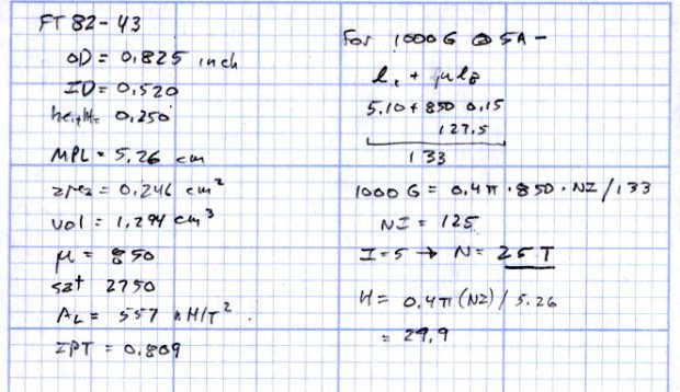
FT82-43 Doodles Doodles for the FT50-61:
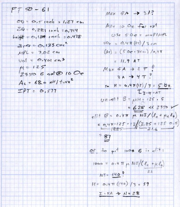
FT50-61 Doodles Running the numbers using the Magnetics Inc equations:
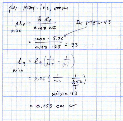
Ferrite Gap Doodles


-
Subscribe
Subscribed
Have a WordPress.com account? Log in now.

