-
Cheap WS2812 LEDs: Test Fixture Mount
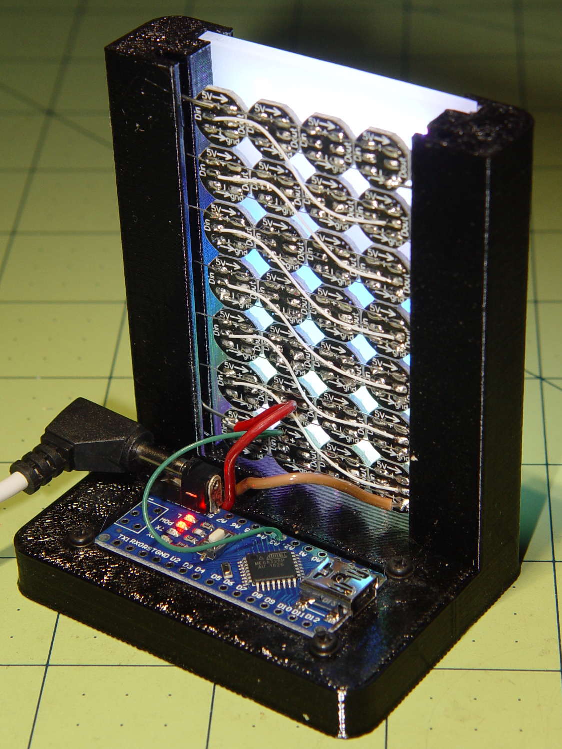
Mounting the ungainly WS2812 LED test fixture seemed like a Good Idea to keep the electricity out of the usual conductive litter:
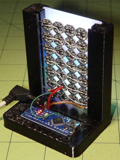
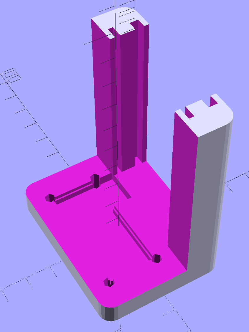
WS2812 array test fixture – rear The solid model shows more details:
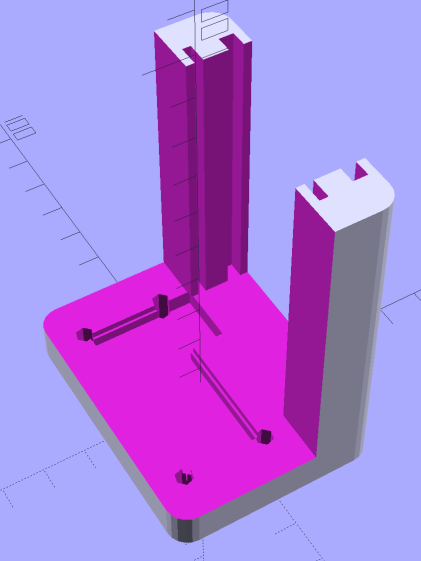
LED Test Fixture – solid model The power wires along the array edges slide into the rear (thinner) slot, with enough friction from a few gentle bends to hold the whole mess in place.
The knockoff Arduino Nano rests on the recessed ledge in the pit, with M2 screws and washers at the corners holding it down (the PCB’s built-in holes might work with 1 mm or 0-90 screws, but that’s just crazy talk). I soldered the power wires directly to the coaxial jack pins under the PCB; they snake out to the LEDs through the little trench. There should be another cutout around the USB connector for in-situ programming, although the existing code works fine.
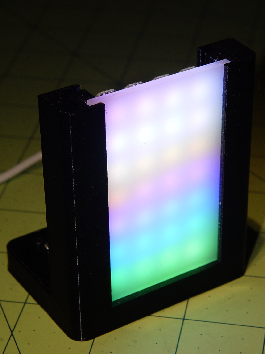
The front (wider) slot holds a piece of translucent white acrylic to diffuse the light:
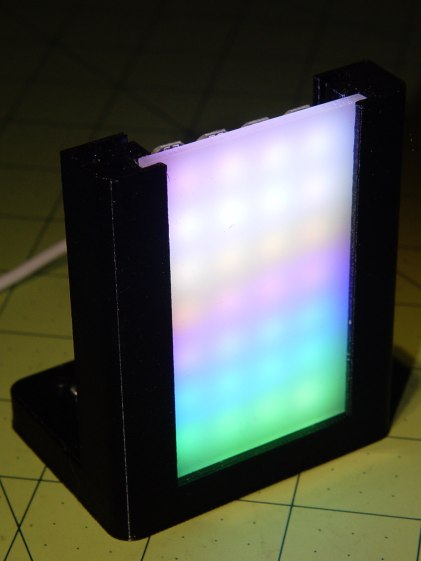
WS2812 array test fixture – front flash It’s painfully bright: a few layers of neutral density filter would be appropriate for a desk toy.
The array runs hot enough at MaxPWM = 255 to produce a gentle upward breeze.
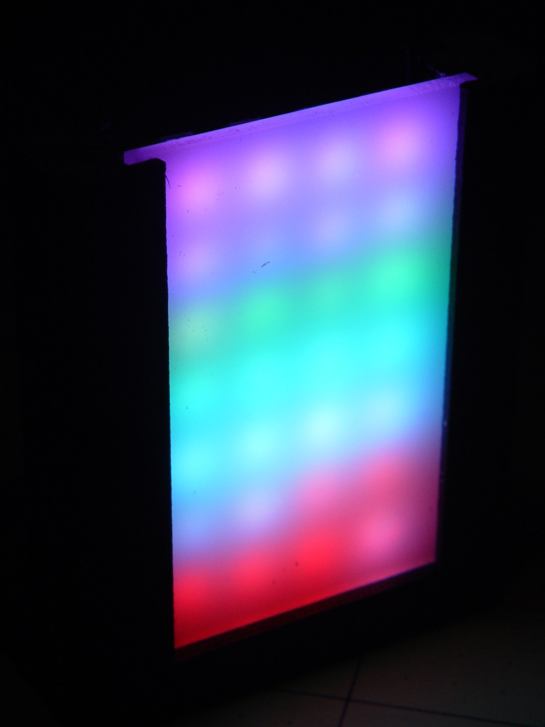
It looks even better without the flash:
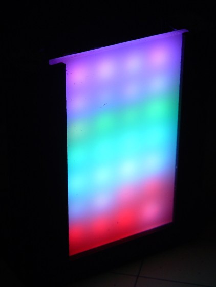
WS2812 array test fixture – front dark You’ll find many easier ways to get RGB LED panels, but that’s not the point here; I’m waiting for these things to die an unnatural death.
The OpenSCAD source code as a GitHub Gist:
This file contains hidden or bidirectional Unicode text that may be interpreted or compiled differently than what appears below. To review, open the file in an editor that reveals hidden Unicode characters. Learn more about bidirectional Unicode characters// LED Test Fixture // Ed Nisley KE4ZNU – February 2017 ClampFlange = true; Channel = false; //- Extrusion parameters – must match reality! ThreadThick = 0.25; ThreadWidth = 0.40; function IntegerMultiple(Size,Unit) = Unit * ceil(Size / Unit); Protrusion = 0.1; HoleWindage = 0.2; //- Screw sizes ID = 0; OD = 1; LENGTH = 2; Insert = [2.8,3.5,4.0]; // M2 threaded insert ScrewOD = 2.0; WasherOD = 5.0; //- Component sizes PCBSize = [18.0,43.5,1.6]; // microcontroller PCB PCBClear = 2*[ThreadWidth,ThreadWidth,0]; // clearance around board PCBShelf = [ThreadWidth,ThreadWidth,0]; // shelf under perimeter PCBCavity = PCBSize – PCBShelf + [0,0,2.5]; // support shelf around bottom parts LEDPanel = [70,40,4.0]; // lying flat, LEDs upward LEDWire = [LEDPanel[0],LEDPanel[1] + 2*5.0,2.0]; // power wires along sides Diffuser = [LEDPanel[0],LEDPanel[1] + 2*4.0,3.5]; echo(str("Diffuser panel: ",Diffuser)); WallThick = 8.0; BaseThick = 3*ThreadThick + Insert[LENGTH] + PCBCavity[2]; Block = [3*WallThick + PCBSize[0] + LEDPanel[2] + Diffuser[2], 2*WallThick + IntegerMultiple(max(PCBSize[1],LEDWire[1]),5), BaseThick + LEDPanel[0]]; echo(str("Block: ",Block)); CornerRadius = 5.0; NumSides = 4*5; //- Adjust hole diameter to make the size come out right module PolyCyl(Dia,Height,ForceSides=0) { // based on nophead's polyholes Sides = (ForceSides != 0) ? ForceSides : (ceil(Dia) + 2); FixDia = Dia / cos(180/Sides); cylinder(r=(FixDia + HoleWindage)/2,h=Height,$fn=Sides); } //- Build it difference() { hull() // main block with rounded corners for (i=[-1,1], j=[-1,1]) translate([i*(Block[0]/2 – CornerRadius),j*(Block[1]/2 – CornerRadius),,0]) cylinder(r=CornerRadius,h=Block[2],$fn=NumSides); translate([2*WallThick + PCBSize[0] – Block[0], 0, (Block[2]/2 + BaseThick)]) cube(Block + [0,2*Protrusion,0],center=true); // cut out over PCB translate([WallThick + (PCBSize + PCBClear)[0]/2 – Block[0]/2, 0, 0]) { translate([0,0,(BaseThick + (Protrusion – PCBSize[2])/2)]) cube(PCBSize + PCBClear + [0,0,Protrusion],center=true); // PCB recess translate([0,0,(BaseThick + (Protrusion – PCBCavity[2])/2)]) cube(PCBCavity + [0,0,Protrusion],center=true); // cavity under PCB translate([PCBSize[0]/2 + WallThick/2 – Protrusion/2,PCBSize[1]/2 – 15/2,BaseThick – PCBCavity[2]/2 + Protrusion/2]) cube([WallThick + PCBShelf[0] + Protrusion, 15,PCBCavity[2] + Protrusion],center=true); // wiring cutout for (i=[-1,1], j=[-1,1]) // screw inserts translate([i*(PCBSize[0] + ScrewOD)/2,j*(PCBSize[1] + ScrewOD)/2,-Protrusion]) rotate(180/(2*6)) PolyCyl(Insert[OD],BaseThick + 2*Protrusion,6); } resize([2*Block[0],0,LEDPanel[0] + Protrusion]) // LED panel outline translate([0,0,BaseThick]) rotate([0,-90,0]) translate([(LEDPanel[0] + Protrusion)/2,0,0]) cube(LEDPanel + [Protrusion,0,0],center=true); translate([-Block[0]/2 + 2*WallThick + PCBSize[0] + LEDWire[2]/2 + 5*ThreadWidth, 0,BaseThick]) // LED wiring recess rotate([0,-90,0]) translate([(LEDWire[0] + Protrusion)/2,0,0]) cube(LEDWire + [Protrusion,0,0],center=true); translate([Block[0]/2 – Diffuser[2]/2 – 5*ThreadWidth,0,BaseThick]) // diffuser rotate([0,-90,0]) translate([(Diffuser[0] + Protrusion)/2,0,0]) cube(Diffuser + [Protrusion,0,0],center=true); }
-
Subscribe
Subscribed
Have a WordPress.com account? Log in now.

