-
MPCNC: Z Axis Upward Homing with Opto Proximity Sensor
Homing the MPCNC’s Z axis at the bottom end of its travel made no sense, but the Z stage lacks a convenient spot to mount / trigger a switch at the top of its travel, so this sufficed for initial tests & fiddling:
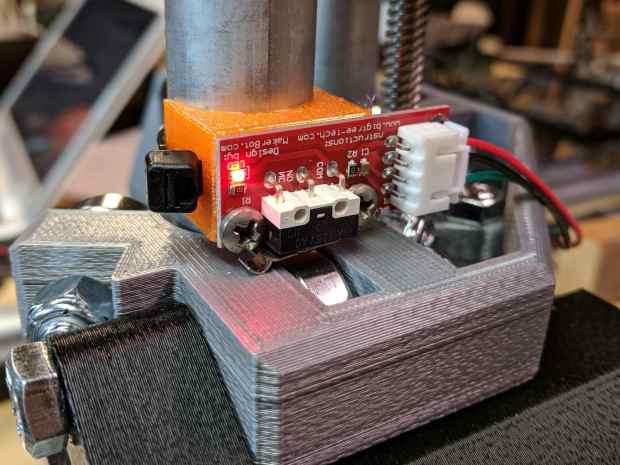
MPCNC – Z min endstop The EMT rail carrying the switch moves downward, tripping the lever when it hits the MPCNC’s central assembly.
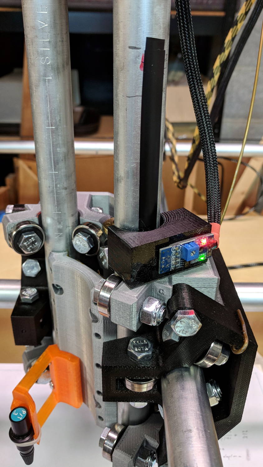
Somewhat to my surprise, a TRCT5000-based optical proximity sensor (harvested from the Kenmore 158 Crash Test Dummy’s corpse) and a strip of black electrical tape work perfectly:
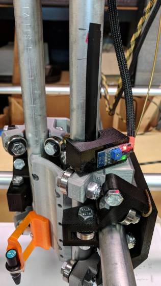
MPCNC – Z Axis Opto Proximity Endstop The PCB wears a shiny new epoxy coat:
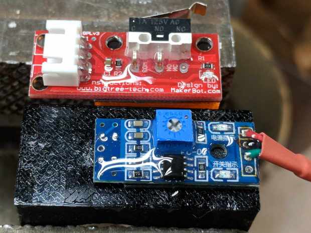
MPCNC – Epoxy-coated Endstop – Opto Prox Sensor I soldered the wires (harvested from the previous endstop) directly to the PCB, because the pinout isn’t the same and fewer connectors should be better.
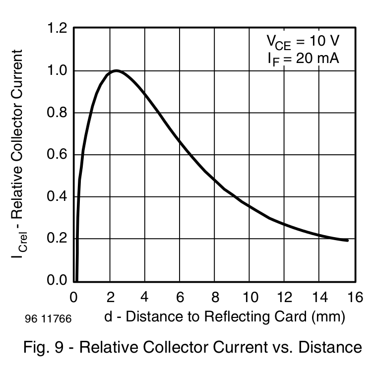
The mount uses black PETG, rather than translucent orange, in hope of IR opacity, and wraps around the EMT rail at (roughly) the 2 mm standoff producing the peak response:
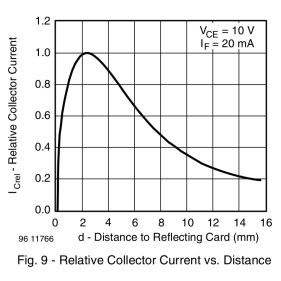
IR Reflective Sensor module – TCRT5000 – response vs distance In truth, I set the gap by eyeballometric guesstimation to make the entire mount arc sit equidistant from the EMT:
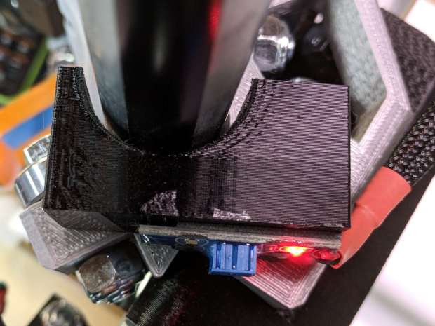
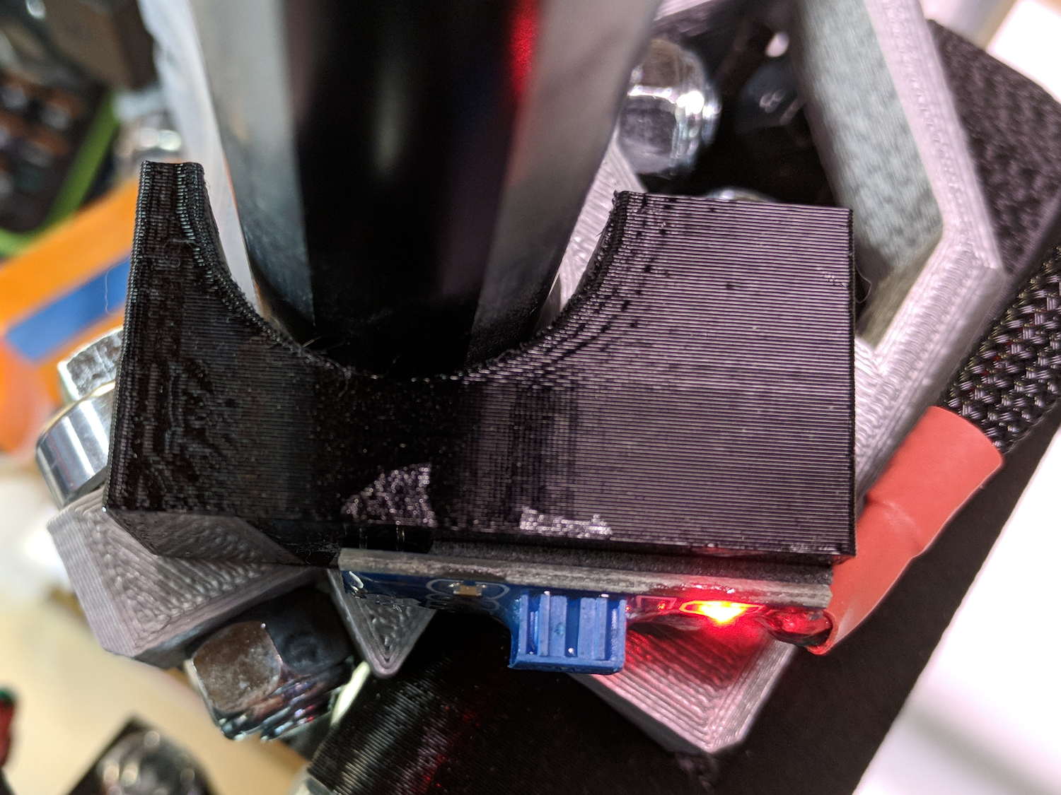
MPCNC – Z Opto Prox Endstop – top view The mount includes the 2 mm spacing around the EMT OD and puts the sensor tip flush with the arc OD, so it should be pretty close:
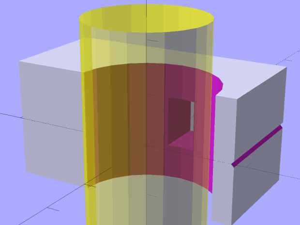
TCRT5000 Z Axis Endstop Mount – solid model A strip of 3M permanent tape, cut to clear the 608 bearings, affixes the mount to the MPCNC’s central assembly. The solid model now includes a midline reference notch, with a height rounded up to the next-highest multiple of 2.0 mm. It needs a loop to anchor the cable.
The blue twiddlepot sets the comparator threshold midway between the response over black tape (incorrectly on = too low) and bare EMT (incorrectly off = too high), in the hope of noise immunity. The range spanned nearly half of the pot rotation, so I think it’s all good.
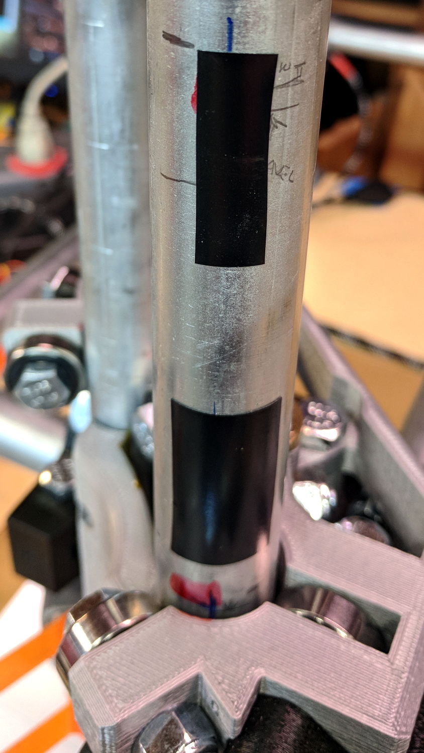
The sensor doesn’t trip when the edge of the tape exactly meets its midline, which meant I had to trim a strip of tape to suit. As part of setting the twiddlepot, I shut off the Z axis motor and laid some test strips on the EMT:
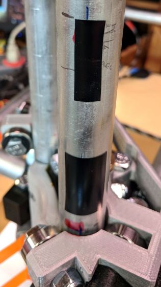
MPCNC – Z Axis Opto Prox Endstop – Test Tape I spun the leadscrew with one hand, held the sensor with the other, twiddled the trimpot, trimmed the upper and lower ends of the tape, and generally had a fine time. The sensor responds equally well to a half-wide strip of tape (in the upper picture), with the distinct advantage of not encroaching on the 608 bearing tracks.
The GRBL setup now homes Y and Z toward the positive end of their travel, with X still toward the negative end while a set of extension cables remains in transit around the planet.
The OpenSCAD source code as a GitHub Gist:
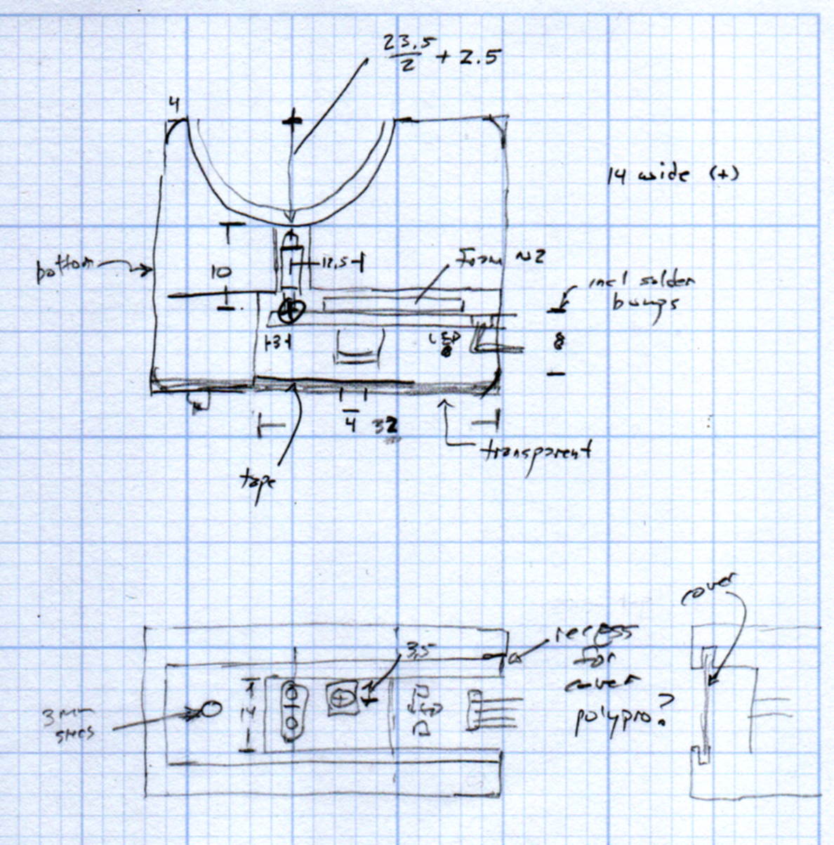
This file contains hidden or bidirectional Unicode text that may be interpreted or compiled differently than what appears below. To review, open the file in an editor that reveals hidden Unicode characters. Learn more about bidirectional Unicode characters// TCRT5000 Z Axis Endstop Mount // Ed Nisley KE4ZNU – 2017-12-04 /* [Build Options] */ Layout = "Show"; // [Build, Show, Block] Section = true; // show internal details /* [Extrusion] */ ThreadThick = 0.25; // [0.20, 0.25] ThreadWidth = 0.40; // [0.40] function IntegerMultiple(Size,Unit) = Unit * ceil(Size / Unit); /* [Hidden] */ Protrusion = 0.01; // [0.01, 0.1] HoleWindage = 0.2; ID = 0; OD = 1; LENGTH = 2; /* [Sizes] */ RailOD = 23.5; // actual rail OD OptoPCB = [32.5,14.2,1.6]; // prox sensor PCB ComponentHeight = 5.0; // max component height above PCB OptoSensor = [5.8,10.2,10.5]; // sensor head below PCB OptoOffset = 3.0; // sensor head center from PCB edge OptoRange = 2.0; // sensor to rail distance TapeThick = 1.0; // foam mounting tape WallThick = 4.0; // basic wall thickness Block = [WallThick + OptoRange + RailOD/2 + (OptoPCB[0] – OptoOffset), RailOD/2 + OptoRange + OptoSensor[2] – TapeThick, IntegerMultiple(OptoPCB[1] + 2*WallThick,2.0)]; // basic block shape echo(str("Block: ",Block)); NumSides = 6*4; //- Adjust hole diameter to make the size come out right module PolyCyl(Dia,Height,ForceSides=0) { // based on nophead's polyholes Sides = (ForceSides != 0) ? ForceSides : (ceil(Dia) + 2); FixDia = Dia / cos(180/Sides); cylinder(r=(FixDia + HoleWindage)/2,h=Height,$fn=Sides); } //- Shapes // Main block constructed with PCB along X, opto sensor at Y=0 module PCBBlock() { difference() { translate([-(WallThick + OptoRange + RailOD/2), (-Block[1] + RailOD/2 + OptoRange), -Block[2]/2]) cube(Block,center=false); for (i=[-(RailOD/2 + OptoRange + WallThick), (OptoPCB[0] – OptoOffset)]) translate([i,0,0]) rotate([90,0,0]) rotate(45) cube([2*ThreadWidth,2*ThreadWidth,2*Block[2]],center=true); translate([0,(RailOD/2 + OptoRange),0]) cylinder(d=(RailOD + 2*OptoRange), h=(Block[2] + 2*Protrusion), $fn=NumSides,center=true); rotate([90,0,0]) cube(OptoSensor + [0,0,Block[1]],center=true); } } //- Build things if (Layout == "Block") PCBBlock(); if (Layout == "Show") { translate([0,-(RailOD/2 + OptoRange),0]) PCBBlock(); color("Yellow",0.5) cylinder(d=RailOD,h=2*Block[2],$fn=NumSides,center=true); } if (Layout == "Build") translate([0,0,OptoSensor[2] – TapeThick]) rotate([90,0,0]) PCBBlock(); The original doodles, including a bunch of ideas left on the cutting room floor:
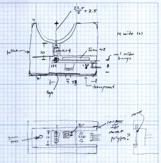
MPCNC Z Opto Proximity Sensor Endstop – doodles



-
Subscribe
Subscribed
Have a WordPress.com account? Log in now.

