-
Tek Circuit Computer: Drag Knife Deck Cutting
Creating a paper version of the Tektronix Circuit Computer requires nothing more than a drag knife to cut the deck outlines:
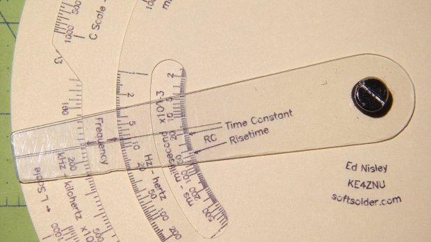
Tek Circuit Computer – cursor hairline The middle deck is a disk with a notch exposing the FL scale, a cutout window exposing the inductive time constant / risetime scale, and a wee circle for the Chicago screw in the middle:
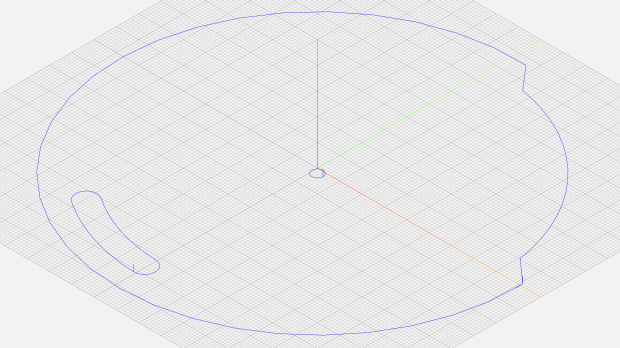
Tek CC – middle deck outline Three angles define the notch:
  FLNotchArc = 85deg;                   // width exposing FL scale
  FLRampArc = 7deg;                     // … width of entry & exit ramps
  FLNotchOffset = 2deg;                 // … start angle from 0°
Given those, along with the deck radius and notch height (equals the underlying scale height), calculate four points defining the start and end of the ramps and connect the dots:
  local a0 = FLNotchOffset;
  local p0 = DeckRad * [cos(a0),sin(a0),-];

  local a1 = a0 + FLNotchArc;
  local p1 = DeckRad * [cos(a1),sin(a1),-];

  goto(p0);
  move([-,-,KnifeZ]);
  arc_cw(p1,-DeckRad);          // largest arc

  local r = DeckRad - ScaleHeight;
  local a3 = a1 - FLRampArc;
  local p3 = r * [cos(a3),sin(a3),-];

  local a4 = a0 + FLRampArc;
  local p4 = r * [cos(a4),sin(a4),-];

  move(p3);
  arc_cw(p4,r);                 // smallest arc

  move(p0);                     // end of notch

  arc_cw([DeckRad,0,-],DeckRad);      // round off corner
The
arc_cw()functions draw arcs, as you’d expect, with a positive radius tracing the shortest arc and a negative radius for the longest arc. Although I know how that works, I must still preview the result to verify the G-Code does what I want, not what I said.The unhappy result of a wrong sign:

Tek CC – middle deck outline – wrong arc sign GCMC uses the (signed) radius to generate the XY coordinates and IJ offsets for
G2commands in the preferred center format:G0 X88.846 Y3.103 G1 Z-2.000 G2 X4.653 Y88.778 I-88.846 J-3.103Cutting the window starts from its angular width and offset, which are hardcoded magic numbers from the Tek artifact, and proceeds similarly:
  local WindowArc = 39deg;

  local ac = -6 * ScaleArc;                  // center of window arc
  local r0 = DeckRad - ScaleHeight;         // outer
  local r1 = DeckRad - 2 * ScaleHeight;     // inner

  local aw = WindowArc - to_deg(atan(ScaleHeight,(r0 + r1)/2));    // window arc minus endcaps

  local p0 = r0 * [cos(ac + aw/2),sin(ac + aw/2),-];
  local p1 = r0 * [cos(ac - aw/2),sin(ac - aw/2),-];
  local p2 = r1 * [cos(ac - aw/2),sin(ac - aw/2),-];
  local p3 = r1 * [cos(ac + aw/2),sin(ac + aw/2),-];

  goto(p0);
  move([-,-,KnifeZ]);

  arc_cw(p1,r0);                          // smallest arc
  arc_cw(p2,ScaleHeight/2);               // half a circle
  arc_ccw(p3,r1);
  arc_cw(p0,ScaleHeight/2);
Trust me on this: incorrect radius signs generate unrecognizable outlines. Which, of course, is why you preview the G-Code before actually cutting anything:
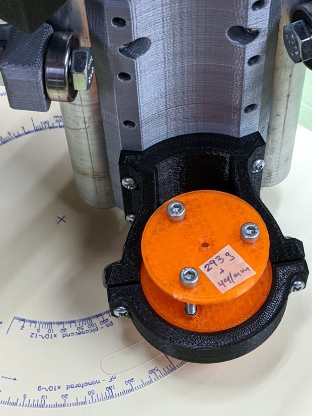
Tek CC – MPCNC drag knife A similar hunk of code cuts the top deck; the bottom deck is a simple circle.
The workflow, such as it is:
- Tape a sheet of paper (Index stock, Basis 110 = 10 mil = 0.25 mm) at the center of the 3018-ProXL platform
- Plot (“engrave”) the scales with a pen
- Affix paper to a Cricut sticky mat taped to the MPCNC platform
- Touch off the origin at the middle
- Drag-cut (“mill”) the outlines
Less complex than it may appear, but the GCMC file now spits out two G-Code files per deck: one to engrave / draw the scales on the 3018 and another to mill / cut the outlines on the MPCNC.
-
Subscribe
Subscribed
Have a WordPress.com account? Log in now.

