-
Glass Tiles: Matrix for SK6812 PCBs
Tweaking the glass tile frame for press-fit SK6812 PCBs in the bottom of the array cells:
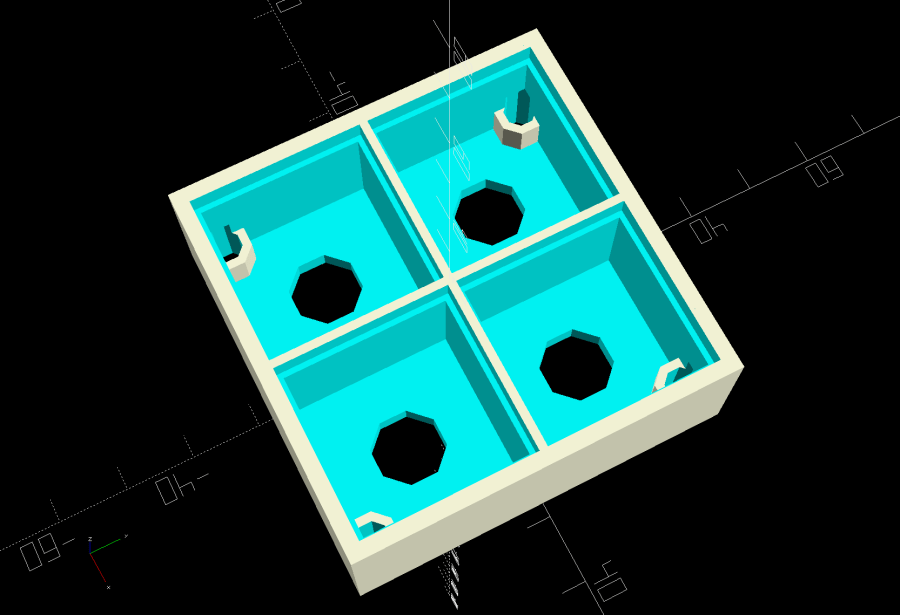
Glass Tile Frame – cell array – openscad Which looks like this with the LEDs and brass inserts installed:
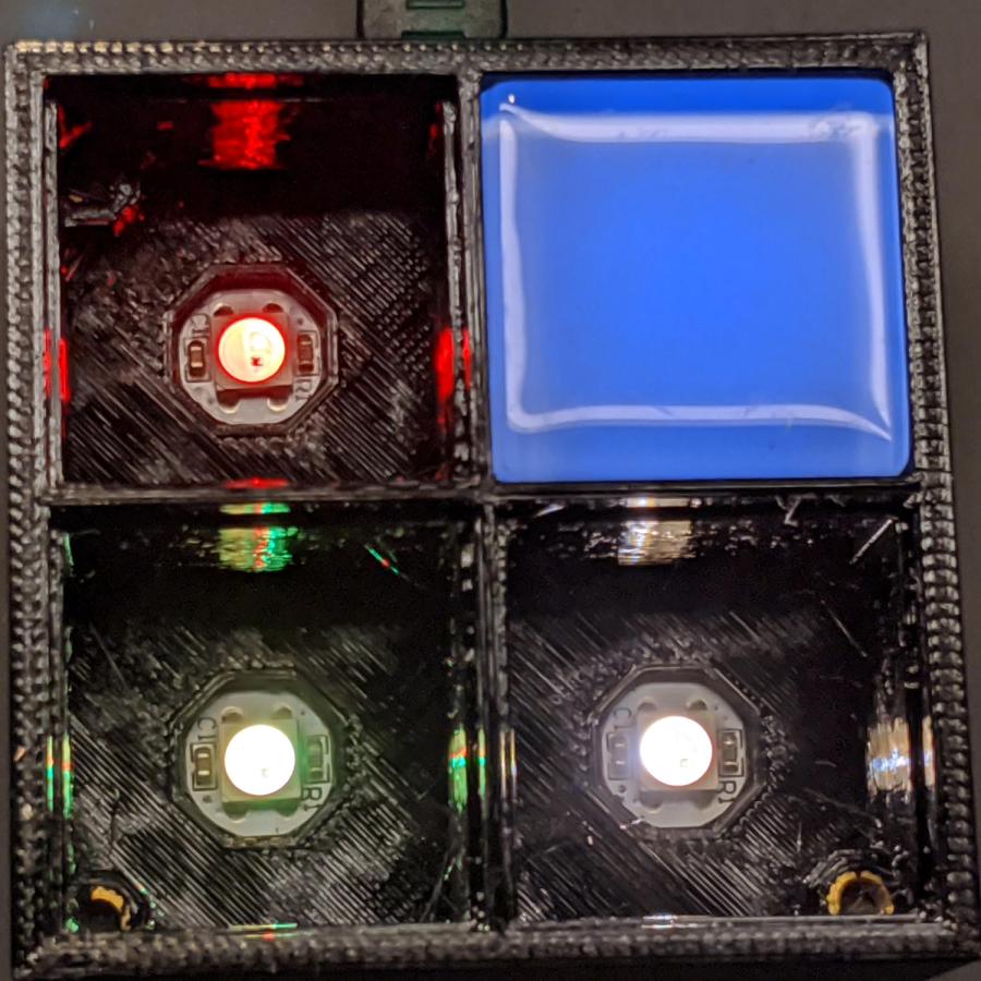
Glass Tile – 2×2 array – interior The base holds an Arduino Nano with room for wiring under the cell array:
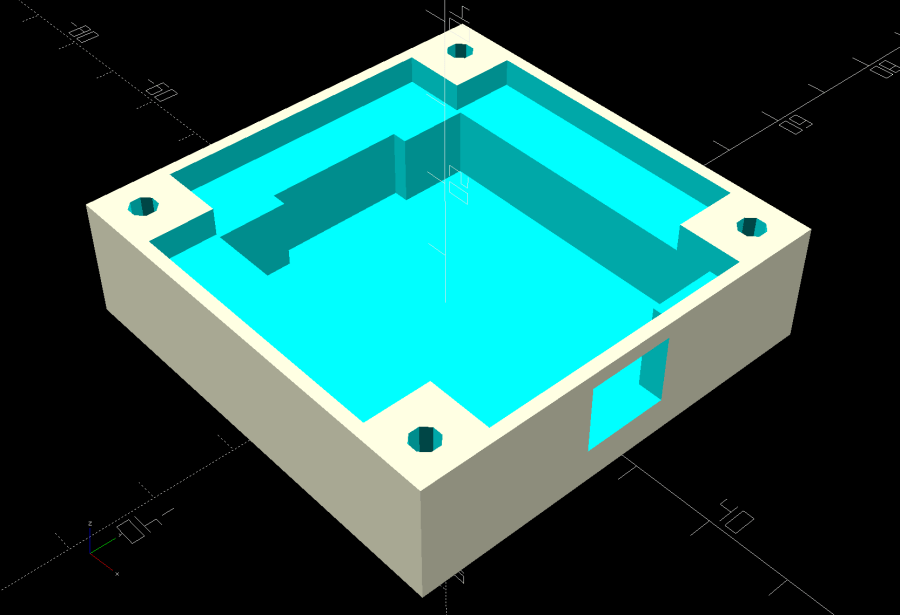
Glass Tile Frame – base – openscad Which looks like this after it’s all wired up:
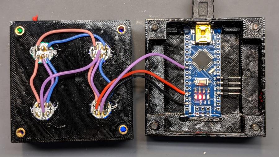
Glass Tile – 2×2 array – wiring The weird colors showing through the inserts are from the LEDs. The red thing in the upper left is a silicone insulation snippet. Yes, that’s hot-melt glue holding the Arduino Nano in place and preventing the PCBs from getting frisky.
Soak a handful of glass tiles overnight in paint stripper:
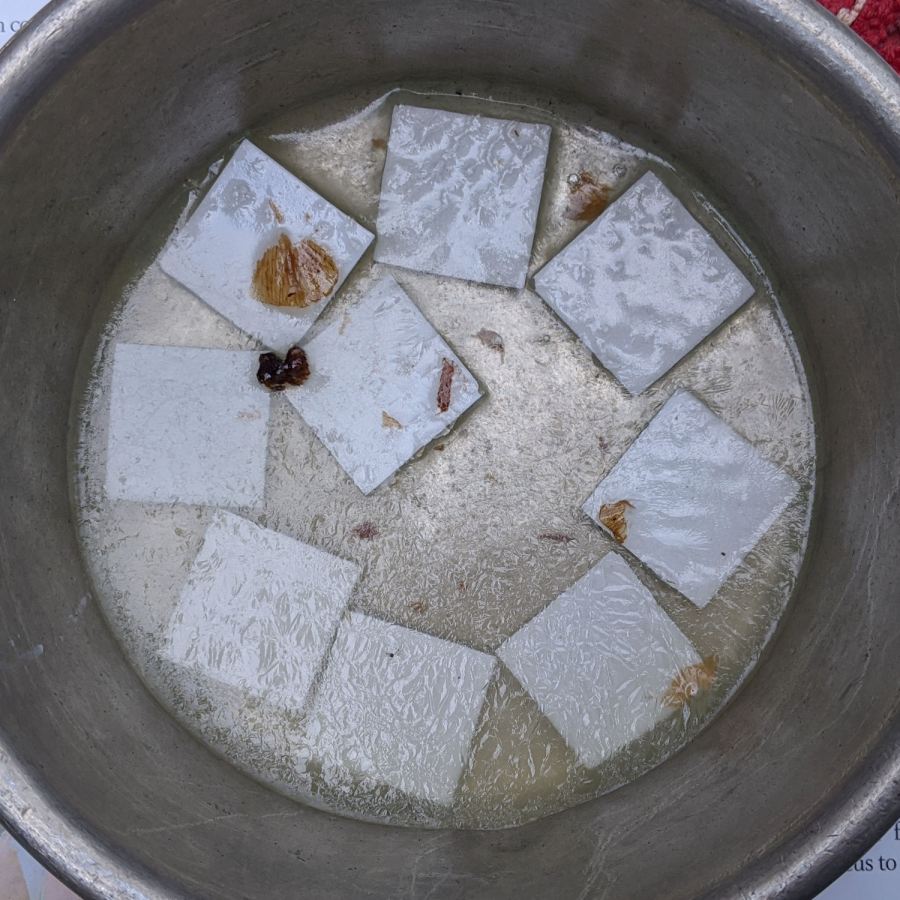
Glass Tiles – paint stripper soak Whereupon the adhesive slides right off with the gentle application of a razor scraper. Rinse carefully, dry thoroughly, and snap into place.
Tighten the four M3 SHCS and it’s all good:
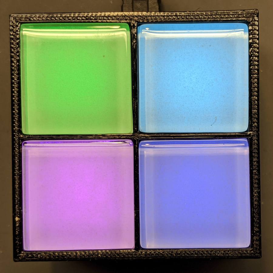
Glass Tile – 2×2 array – operating So far, I’ve had two people tell me they don’t know what it is, but they want one:

Glass Tile – various versions The OpenSCAD Customizer lets you set the array size:
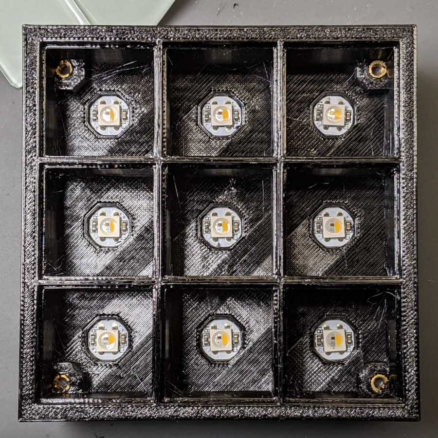
Glass Tile Frame – 3×3 – press-fit SK6812 LEDs However, just because you can do something doesn’t mean you should:

Glass Tile Frame – 6×6 cell array – openscad Something like this might be interesting:

Glass Tile Frame – 2×6 cell array – openscad In round numbers, printing the frame takes about an hour per cell, so a 2×2 array takes three hours and 3×3 array runs around seven hours. A 6×6 frame is just not happening.
The OpenSCAD source code as a GitHub Gist:
This file contains hidden or bidirectional Unicode text that may be interpreted or compiled differently than what appears below. To review, open the file in an editor that reveals hidden Unicode characters. Learn more about bidirectional Unicode characters// Illuminated Tile Grid // Ed Nisley – KE4ZNU // 2020-05 /* [Configuration] */ Layout = "Build"; // [Cell,CellArray,MCU,Base,Show,Build] Shape = "Square"; // [Square, Pyramid, Cone] Cells = [2,2]; CellDepth = 15.0; Inserts = true; SupportInserts = true; /* [Hidden] */ ThreadThick = 0.25; ThreadWidth = 0.40; HoleWindage = 0.2; function IntegerMultiple(Size,Unit) = Unit * ceil(Size / Unit); Protrusion = 0.1; // make holes end cleanly ID = 0; OD = 1; LENGTH = 2; Tile = [25.0 + 0.1,25.0 + 0.1,4.0]; WallThick = 4*ThreadWidth; FloorThick = 3.0; Flange = [2*ThreadWidth,2*ThreadWidth,0]; // ridge supporting tile Separator = [3*ThreadWidth,3*ThreadWidth,Tile.z – 1]; // between tiles Screw = [3.0,6.0,3.5]; // M3 SHCS, OD=head, LENGTH=head Insert = [3.0,4.2,8.0]; // threaded brass insert ScrewRecess = Screw[LENGTH] + 4*ThreadThick; LEDPCB = [9.6,9.6,2.9]; // round SK6812, squared-off sides LED = [5.0 + 2*HoleWindage,5.0 + 2*HoleWindage,1.3]; LEDOffset = [0.0,0.0,0.0]; // if offset from PCB center CellOAL = [Tile.x,Tile.y,0] + Separator + [0,0,CellDepth] + [0,0,FloorThick]; ArrayOAL = [Cells.x*CellOAL.x,Cells.y*CellOAL.y,CellOAL.z]; // just the LED cells BlockOAL = ArrayOAL + [2*WallThick,2*WallThick,0]; // LED cells + exterior wall echo(str("Block OAL: ",BlockOAL)); InsertOC = ArrayOAL – [Insert[OD],Insert[OD],0] – [WallThick,WallThick,0]; echo(str("Insert OC: ",InsertOC)); TapeThick = 1.0; Arduino = [44.0,18.0,8.0 + TapeThick]; // Arduino Nano to top of USB Mini-B plug USBPlug = [15.0,11.0,9.0]; // USB Mini-B plug insulator USBOffset = [0,0,5.0]; // offset from PCB base WiringSpace = 3.5; WiringBay = [(Cells.x – 1)*CellOAL.x + LEDPCB.x,(Cells.y – 1)*CellOAL.y + LEDPCB.x,WiringSpace]; PlateOAL = [BlockOAL.x,BlockOAL.y,FloorThick + Arduino.z + WiringSpace]; // allow wiring above Arduino echo(str("Base Plate: ",PlateOAL)); echo(str("Screw length: ",(PlateOAL.z – ScrewRecess) + Insert.z/2," to ",(PlateOAL.z – ScrewRecess) + Insert.z)); LegendRecess = 1*ThreadThick; //———————— module PolyCyl(Dia,Height,ForceSides=0) { // based on nophead's polyholes Sides = (ForceSides != 0) ? ForceSides : (ceil(Dia) + 2); FixDia = Dia / cos(180/Sides); cylinder(d=(FixDia + HoleWindage),h=Height,$fn=Sides); } //———————– // Base and optics in single tile module LEDCone() { hull() { translate([0,0,CellDepth + Tile.z/2]) cube(Tile – 2*[Flange.x,Flange.y,0],center=true); if (Shape == "Square") { translate([0,0,LEDPCB.z/2]) cube([Tile.x,Tile.y,LEDPCB.z] – 2*[Flange.x,Flange.y,0],center=true); } else if (Shape == "Pyramid") { translate([0,0,LEDPCB.z/2]) cube(LEDPCB,center=true); } else if (Shape == "Cone") { translate([0,0,LEDPCB.z/2]) cylinder(d=1.0*LEDPCB.x,h=LED.z,center=true); } else { echo(str("Whoopsie! Invalid Shape: ",Shape)); cube(5); } } } // One complete LED cell module LEDCell() { difference() { translate([0,0,CellOAL.z/2]) cube(CellOAL + [Protrusion,Protrusion,0],center=true); // force overlapping adjacent sides! translate([0,0,CellOAL.z – Separator.z + Tile.z/2]) cube(Tile,center=true); translate([0,0,LEDPCB.z]) LEDCone(); // cube([LED.x,LED.y,CellOAL.z],center=true); translate(-LEDOffset + [0,0,-CellOAL.z/2]) rotate(180/8) PolyCyl(LEDPCB.x,CellOAL.z,8); } } // The whole array of cells module CellArray() { difference() { union() { translate([CellOAL.x/2 – Cells.x*CellOAL.x/2,CellOAL.y/2 – Cells.y*CellOAL.y/2,0]) for (i=[0:Cells.x – 1], j=[0:Cells.y – 1]) translate([i*CellOAL.x,j*CellOAL.y,0]) LEDCell(); if (Inserts) // bosses for (i=[-1,1], j=[-1,1]) translate([i*InsertOC.x/2,j*InsertOC.y/2,0]) rotate(180/8) cylinder(d=Insert[OD] + 2*WallThick,h=Insert[LENGTH],$fn=8); } if (Inserts) // holes for (i=[-1,1], j=[-1,1]) translate([i*InsertOC.x/2,j*InsertOC.y/2,-Protrusion]) rotate(180/8) PolyCyl(Insert[OD],Insert[LENGTH] + FloorThick + Protrusion,8); } difference() { translate([0,0,CellOAL.z/2]) cube(BlockOAL,center=true); translate([0,0,CellOAL.z]) cube(ArrayOAL + [0,0,2*CellOAL.z],center=true); } } // Arduino bounding box // Origin at center bottom of PCB module Controller() { union() { translate([0,0,Arduino.z/2]) cube(Arduino,center=true); translate([Arduino.x/2 – Protrusion,-USBPlug.y/2,USBOffset.z + TapeThick – USBPlug.z/2]) cube(USBPlug + [Protrusion,0,0],center=false); } } // Baseplate module BasePlate() { difference() { translate([0,0,PlateOAL.z/2]) cube(PlateOAL,center=true); translate([PlateOAL.x/2 – Arduino.x/2 – 2*WallThick,0,FloorThick]) Controller(); translate([PlateOAL.x/2 – Arduino.x/2 – 2*WallThick,0,FloorThick + PlateOAL.z/2]) cube([Arduino.x – 2*2.0,WiringBay.y,PlateOAL.z],center=true); // cutouts beside MCU translate([0,0,PlateOAL.z – WiringBay.z + PlateOAL.z/2 – Protrusion]) cube([PlateOAL.x – 2*WallThick,WiringBay.y,PlateOAL.z],center=true); // cutout above MCU translate([0,0,PlateOAL.z – WiringBay.z + PlateOAL.z/2 – Protrusion]) cube([WiringBay.x,PlateOAL.y – 2*WallThick,PlateOAL.z],center=true); // cutout above MCU if (Inserts) for (i=[-1,1], j=[-1,1]) translate([i*InsertOC.x/2,j*InsertOC.y/2,-Protrusion]) rotate(180/8) { PolyCyl(Screw[ID],2*PlateOAL.z,8); PolyCyl(Screw[OD],ScrewRecess + Protrusion,8); } cube([45,17.0,2*LegendRecess],center=true); } linear_extrude(height=2*LegendRecess) { translate([0,1]) rotate(-0*90) mirror([1,0,0]) text(text="Ed Nisley",size=6,font="Arial:style:Bold",halign="center"); translate([0,-6.5]) rotate(-0*90) mirror([1,0,0]) text(text="softsolder.com",size=4.5,font="Arial:style:Bold",halign="center"); } Fin = [Screw[OD]/2 – 1.5*ThreadWidth,2*ThreadWidth,ScrewRecess – ThreadThick]; if (Inserts && SupportInserts) color("Yellow") for (i=[-1,1], j=[-1,1]) translate([i*InsertOC.x/2,j*InsertOC.y/2,0]) { rotate(180/8) cylinder(d=6*ThreadWidth,h=ThreadThick,$fn=8); for (a=[0:90:360]) rotate(a) translate([Fin.x/2 + ThreadWidth/2,0,(ScrewRecess – ThreadThick)/2]) cube(Fin,center=true); } } //———————– // Build things if (Layout == "Cell") LEDCell(); else if (Layout == "CellArray") CellArray(); else if (Layout == "MCU") Controller(); else if (Layout == "Base") BasePlate(); else if (Layout == "Show") { translate([0,0,3*PlateOAL.z]) CellArray(); BasePlate(); translate([PlateOAL.x/2 – Arduino.x/2 – 2*WallThick,0,FloorThick]) color("Orange",0.3) Controller(); } else if (Layout == "Build") union() { translate([0,0.6*BlockOAL.y,0]) CellArray(); translate([0,-0.6*BlockOAL.x,0]) rotate(90) BasePlate(); }
-
Subscribe
Subscribed
Have a WordPress.com account? Log in now.

