Ed Nisley's Blog: Shop notes, electronics, firmware, machinery, 3D printing, laser cuttery, and curiosities. Contents: 100% human thinking, 0% AI slop.
Category: Software
General-purpose computers doing something specific
Ejecting the CD after cdparanoid finishes with it provides a visual cue for the next step.
Set up the disk number and maximum number of tracks, then unleash lame:
d=1
tm=19
for t in $(seq -w 1 $tm) ; do lame --preset tape --tt "D${d}:T${t}" --ta "Michael Lewis" --tl "The Big Short" --tn "${t}/${tm}" --tg "Audio Book" --add-id3v2 track${t}.cdda.wav D${d}-${t}.mp3 ; done
rm track*
The $(seq -w 1 $tm) expansion generates a list of zero-filled numbers for the tracks.
There’s surely a one-liner to extract $tm, the maximum track number, from the track* files, but I’ll leave that for later.
You can increment the disk number with let "d++" if the ripping goes smoothly. If not, that’s fraught with peril, because you (well, I) will do it once too often.
Iterate for each CD in the set, washing & primping as needed for good results.
USB WiFi dongle (in power hog mode) on a short extension cable for better reception
As much hardware doc as you need:
RPi Streaming Player – first lashup
The green plug leads off to a set of decent-quality PC speakers with far more bass drive than seems absolutely necessary in this context. The usual eBay vendor bungled an order for the adapter between the RCA line-out jacks and the 3.5 mm plug that will avoid driving the speakers from the UCA202’s headphone monitor output; I doubt that will make any audible difference. If you need an adapter with XLR female to 1/4 inch mono, let me know…
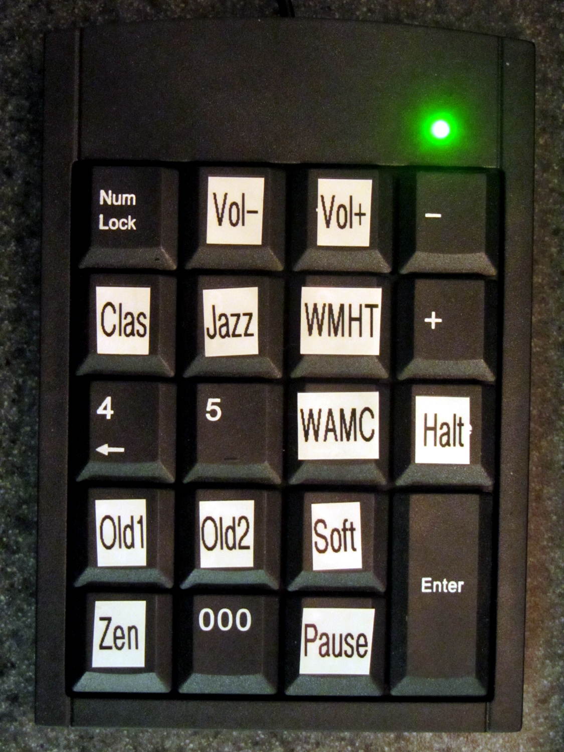
The keypad labels provide all the UI documentation there is:
This file contains hidden or bidirectional Unicode text that may be interpreted or compiled differently than what appears below. To review, open the file in an editor that reveals hidden Unicode characters.
Learn more about bidirectional Unicode characters
The Media dictionary relates keycodes with the command line parameters required to fire mplayer at the streaming stations. With that running, the Controls dictionary turns keycodes into mplayer keyboard controls.
There’s no display: you have no idea what’s going on. I must start the program manually through an ssh session and can watch mplayer‘s console output.
Poking the Halt button forcibly halts the RPi, after which you squeeze the Reset button to reboot the thing. There’s no indication that it’s running, other than sound coming out of the speakers, and no way to tell it fell of the rails other than through the ssh session.
The loop blocks on events, so it can’t also extract stream titles from the (not yet implemented) mplayer stdout pipe / file and paste them on the (missing) display; that’s gotta go.
There’s a lot not to like about all that, of course, but it’s in the tradition of getting something working to discover how it fails and, in this case, how it sounds, which is even more important.
The general idea is to use keystrokes plucked from a cheap numeric keypad to control mplayer, with the intent of replacing some defunct CD players and radios and suchlike. The keypads look about like you’d expect:
Numeric keypads
The keypad layouts are, of course, slightly different (19 vs 18 keys!) and they behave differently with regard to their NumLock state, but at least they produce the same scancodes for the corresponding keys. The black (wired) keypad has a 000 button that sends three 0 events in quick succession, which isn’t particularly useful in this application.
With the appropriate udev rule in full effect, this Python program chews its way through incoming events and reports only the key-down events that will eventually be useful:
This file contains hidden or bidirectional Unicode text that may be interpreted or compiled differently than what appears below. To review, open the file in an editor that reveals hidden Unicode characters.
Learn more about bidirectional Unicode characters
e.type is numeric, so just compare against evcodes.EV_KEY
KeyEvent(e).scancode is the numeric key identifier
KeyEvent(e).keystate = 1 for the initial press
Those KeyEvent(e).key_down/up/hold values don’t change
If you can type KEY_KP0 correctly, wrapping it in quotes isn’t such a big stretch, so I don’t see much point to running scancodes through ecodes.KEY[KeyEvent(e).scancode] just to compare the enumerations.
I’m surely missing something Pythonic, but I don’t get the point of attaching key_down/up/holdconstants to the key event class. I suppose that accounts for changed numeric values inside inherited classes, but … sheesh.
Anyhow, that loop looks like a good starting point.
Mary asked for a less angular version of the Lip Balm Holder, which gave me a chance to practice my list comprehension:
Improved Lipstick and Balm Holder
You hand the OpenSCAD program a list of desired tube diameters in the order you want them, the program plunks the first one (ideally, the largest diameter) in the middle, arranges the others around it counterclockwise from left to right, then slips a lilypad under each tube.
As long as you don’t ask for anything egregiously stupid, the results look reasonably good:
Improved Lipstick and Balm Holder – 8 tubes
As before, each tube length is 1.5 times its diameter; the lipsticks / balms fit loosely and don’t flop around.
Given the tube diameters and the wall thickness, list comprehensions simplify creating lists of the radii from the center tube to each surrounding tube, the center-to-center distances between each of the outer tubes, and the angles between successive tubes:
// per-tube info, first element forced to 0 to make entries match RawDia vector indexes

Radius = [0, for (i=[1:NumTubes-1]) (TubeRad[0] + TubeRad[i] + Wall)];			// Tube[i] distance to center pointRadius = [0, for (i=[1:NumTubes-1]) (TubeRad[0] + TubeRad[i] + Wall)];			// Tube[i] distance to center point
echo(str("Radius: ",Radius));

CtrToCtr = [0, for (i=[1:NumTubes-2]) (TubeRad[i] + TubeRad[i+1] + Wall)];		// Tube[i] distance to Tube[i+1]
echo(str("CtrToCtr: ",CtrToCtr));

Angle = [0, for (i=[1:NumTubes-2]) acos((pow(Radius[i],2) + pow(Radius[i+1],2) - pow(CtrToCtr[i],2)) / (2 * Radius[i] * Radius[i+1]))];
echo(str("Angle: ",Angle));

TotalAngle = sumv(Angle,len(Angle)-1);
echo(str("TotalAngle: ",TotalAngle));
The angles come from the oblique triangle solution when you know all three sides (abc) and want the angle (C) between a and b:
C = arccos( (a2 + b2 - c2) / (2ab) )
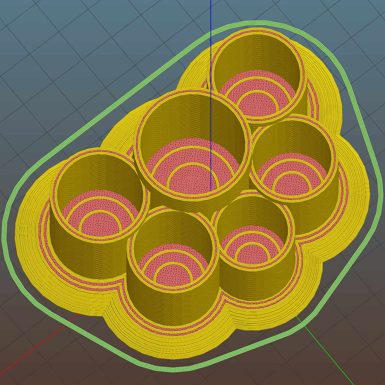
Peering down inside, the Slic3r preview shows the lily pads are the tops of squashed spheres:
Improved Lipstick and Balm Holder – Slic3r preview
The pads are 2.0 times the tube diameter, which seemed most pleasing to the eye. They top out at 2.0 mm thick, which might make the edges too thin for comfort.
I’m awaiting reports from My Spies concerning the typical diameter(s) of lipstick tubes, then I’ll run off a prototype and see about the lily pad edges.
The OpenSCAD source code as a GitHub gist:
This file contains hidden or bidirectional Unicode text that may be interpreted or compiled differently than what appears below. To review, open the file in an editor that reveals hidden Unicode characters.
Learn more about bidirectional Unicode characters
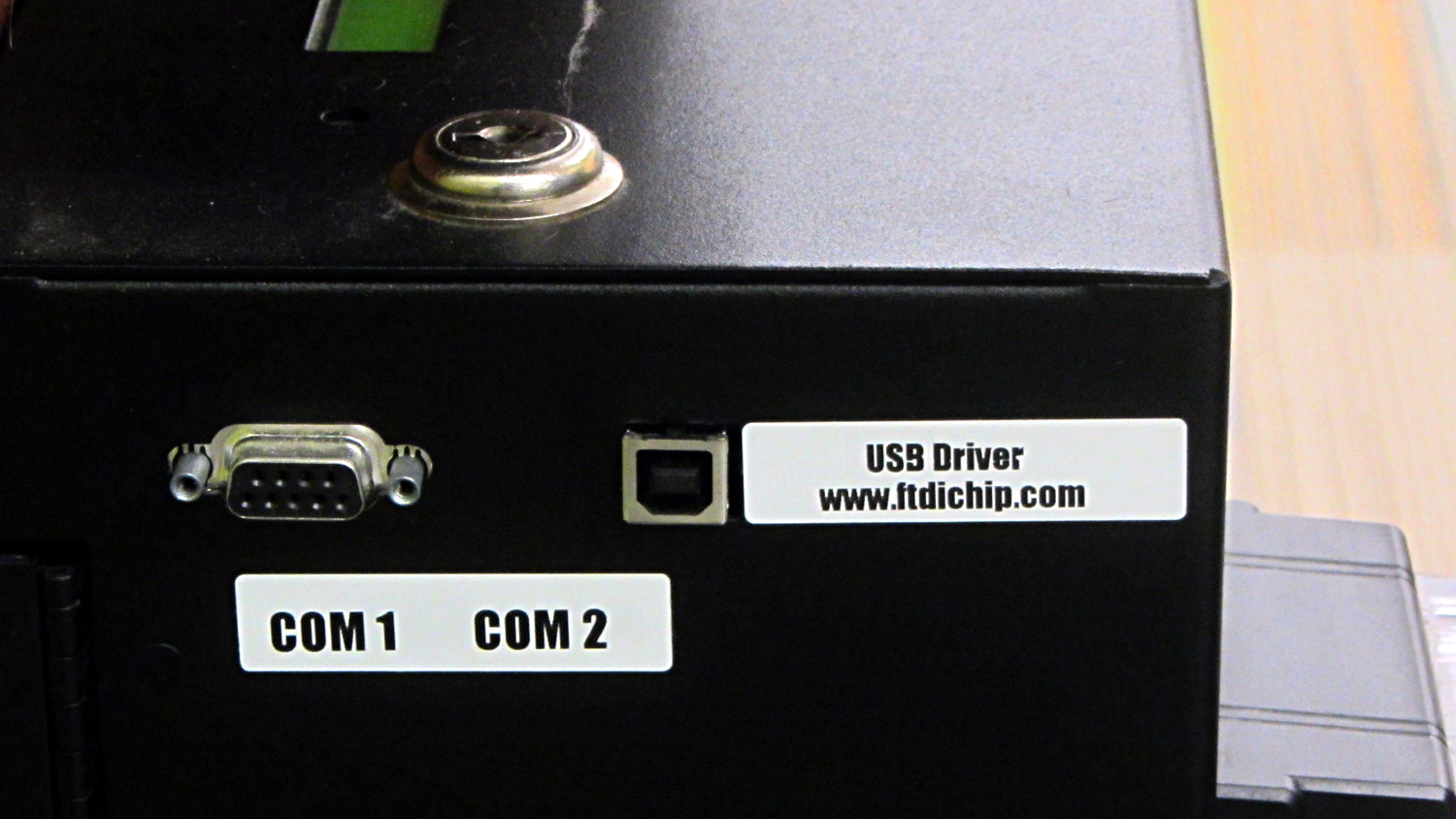
The library kiosk that handles paying your overdue book fines:
Fine payment kiosk with driver info
Now, you’d need to know a few things about what’s going on inside, but I’d say they’re pretty much rolling out the welcome mat for you to find those things out…
Wanna bet it’s running Windows, just like all the electronic voting machines?
Sorta like wedding pictures: you can expose for the groom-in-black or the bride-in-white, but not both at the same time.
The wireless keypad does not have a slot for the USB radio: put ’em in a bag to keep ’em together when not in use.
The general idea is to create a standard name (/dev/input/keypad) for either keypad when it gets plugged in, so the program need not figure out the device name from first principles. This being an embedded system, I can ensure only one keypad will be plugged in at any one time.
The wired keypad has an odd name that makes a certain perverse sense:
That may be because the 0x06a2 Vendor ID was cloned (that’s pronounced “ripped-off”) from Creative Labs. My guess is they ripped the entire chipset, because the 0x4101 device ID came from a Creative Labs wireless keyboard + mouse:
lsusb
... snippage ...
Bus 001 Device 011: ID 062a:4101 Creative Labs
... snippage ...
Because it’s a dual-mode wireless device, we need more information to create the corresponding udev rule. The keyboard part appears (on this boot) as event0, which we find thusly:
ll /dev/input/by-id
total 0
lrwxrwxrwx 1 root root 9 Feb  5 17:39 usb-Burr-Brown_from_TI_USB_Audio_CODEC-event-if03 -> ../event1
lrwxrwxrwx 1 root root 9 Feb  5 17:39 usb-MOSART_Semi._2.4G_Keyboard_Mouse-event-kbd -> ../event0
lrwxrwxrwx 1 root root 9 Feb  5 17:39 usb-MOSART_Semi._2.4G_Keyboard_Mouse-if01-event-mouse -> ../event2
lrwxrwxrwx 1 root root 9 Feb  5 17:39 usb-MOSART_Semi._2.4G_Keyboard_Mouse-if01-mouse -> ../mouse0
Some spelunking suggests using the environment variables set up by the default udev rules, which we find thusly:
sudo udevadm control --reload
sudo udevadm trigger
And then It Just Works:
ll /dev/input/by-id
total 0
lrwxrwxrwx 1 root root 9 Feb  5 17:39 usb-Burr-Brown_from_TI_USB_Audio_CODEC-event-if03 -> ../event1
lrwxrwxrwx 1 root root 9 Feb  5 19:03 usb-MOSART_Semi._2.4G_Keyboard_Mouse-event-kbd -> ../event0
lrwxrwxrwx 1 root root 9 Feb  5 19:03 usb-MOSART_Semi._2.4G_Keyboard_Mouse-if01-event-mouse -> ../event2
lrwxrwxrwx 1 root root 9 Feb  5 19:03 usb-MOSART_Semi._2.4G_Keyboard_Mouse-if01-mouse -> ../mouse0ll /dev/input

ll /dev/input
total 0
drwxr-xr-x 2 root root     120 Feb  5 19:03 by-id
drwxr-xr-x 2 root root     120 Feb  5 19:03 by-path
crw-rw---- 1 root input 13, 64 Feb  5 19:03 event0
crw-rw---- 1 root input 13, 65 Feb  5 17:39 event1
crw-rw---- 1 root input 13, 66 Feb  5 19:03 event2
lrwxrwxrwx 1 root root       6 Feb  5 19:03 keypad -> event0
crw-rw---- 1 root input 13, 63 Feb  5 17:39 mice
crw-rw---- 1 root input 13, 32 Feb  5 19:03 mouse0
My configuration hand is strong…
Note: Once again, I manually restored the source code after the WordPress “improved” editor shredded it by replacing all the double-quote and greater-than symbols inside the “protected” sourcecode blocks with their HTML-escaped equivalents. Some breakage may remain and, as always, WP can shred sourcecode blocks even if I don’t edit the post. They’ve (apparently) banned me from contacting Support, because of an intemperate rant based on years of having them ignore this (and other) problems. I didn’t expect any real help, so this isn’t much of a step backwards in terms of actual support …
Mostly, I don’t worry about the accumulation of old kernels building up in /boot and sudo apt-get autoremove may scrub most of them, but sometimes it doesn’t when I’m doing something else and I must wade through the accumulation of old packages in Synaptic. Removing all those packages by hand gets tedious, but I’m reluctant to unleash a rarely used script on the clutter for fear of creating a worse problem.
The iterator in this burst of Bash line noise:
for f in $(ls /boot | grep vmlinuz | cut -d\- -f2,3 | sort | head -n -1) ; do dpkg -l | grep "^ii\ \ linux-" | grep $f | cut -d" " -f 3 >> /tmp/pkgs.txt ; done
… parses the list of kernels in /boot into version numbers, finds the corresponding installed packages, sorts them in ascending order, discards the last entry so as to not uninstall the most recent kernel, and passes each line of the resulting list into the loop.
N.B: The grep argument has two spaces after the ii that WordPress would destroy without the escaping backslashes. You can try "^ii linux-", but if the loop puts nothing in the file, that’s why.
Given each kernel version number, the loop extracts the package names from the installed kernel packages and glues the result onto a file that looks like this: