Ed Nisley's Blog: Shop notes, electronics, firmware, machinery, 3D printing, laser cuttery, and curiosities. Contents: 100% human thinking, 0% AI slop.
Category: Software
General-purpose computers doing something specific
Slowing the SPI clock and updating the drivers having had no noticeable effect on the OLED display corruption, I once again pondered the SH1106 controller timing specs.
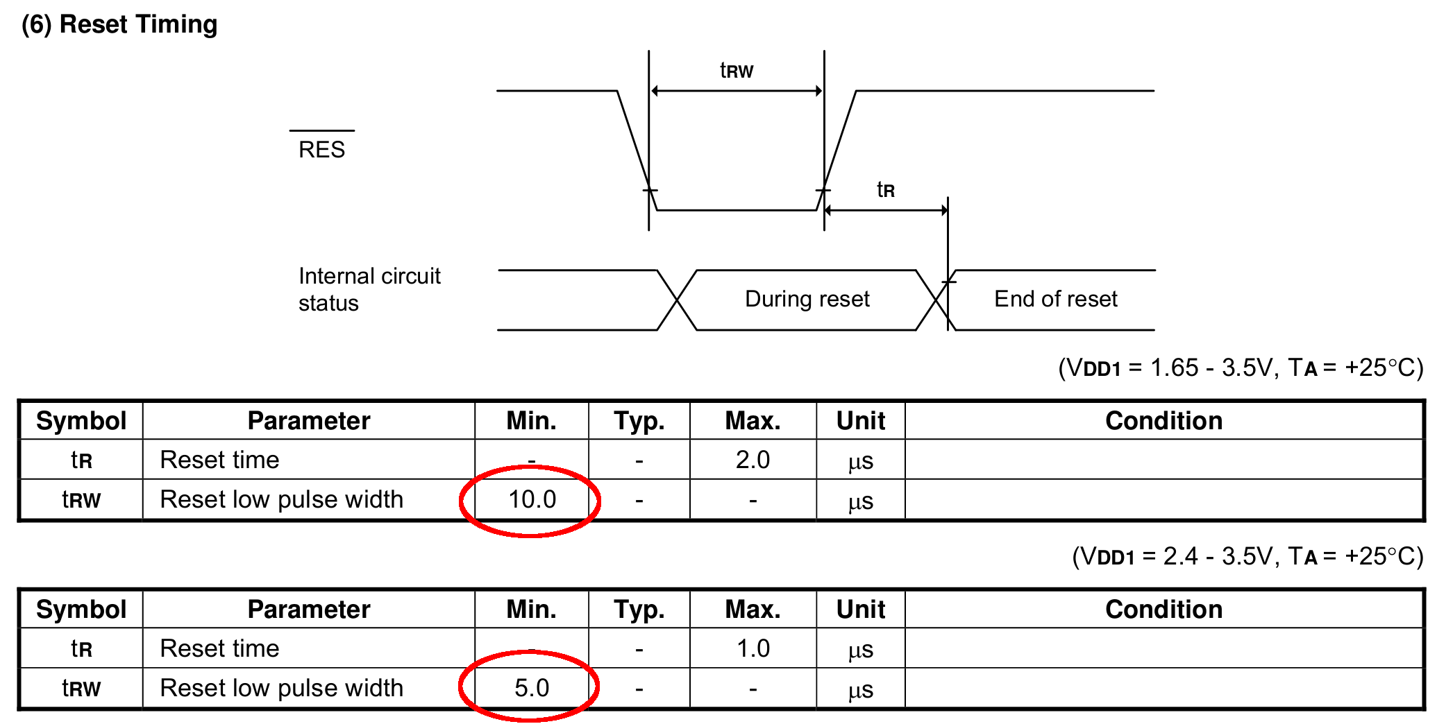
The chip reset seems remarkably slow, even at maximum VCC:
SH1106 – Reset Timing Specs
I think the relevant code is in the luma.core driver’s serial.py file. On the RPi, it resides in /usr/local/lib/python2.7/dist-packages/luma/core/interface/.
As far as I can tell, the bitbang class handles all the setup and teardown around the actual data transfers, but it’s not clear (to me, anyway) how it interacts with the underlying hardware SPI machinery.
So, let’s add some sleepiness to the Reset code:
        if self._RST is not None:
            self._gpio.output(self._RST, self._gpio.LOW)  # Reset device
            time.sleep(1.0e-3)
            self._gpio.output(self._RST, self._gpio.HIGH)  # Keep RESET pulled high
            time.sleep(1.0e-3)
A few milliseconds, rather than a few (hundred) microseconds, won’t make any perceptible difference.
Similarly, the Chip Select and Address (Command/Data) signals require more delay than might occur between successive Python statements:
SH1106 – SPI Address and Select Timing Specs
This should do the trick, again with excessive delay:
        if self._DC:
            self._gpio.output(self._DC, self._cmd_mode)
            time.sleep(1.0e-3)

... snippage ...

        if self._DC:
            self._gpio.output(self._DC, self._data_mode)
            time.sleep(1.0e-3)

... snippage ...

        if self._CE:
            gpio.output(self._CE, gpio.LOW)  # Active low
            time.sleep(1.0e-3)

... snippage ...

        if self._CE:
            gpio.output(self._CE, gpio.HIGH)
            time.sleep(1.0e-3)
Although it shouldn’t be necessary, I blew away the pyc files to prevent future confusion over who’s doing what with which.
Once again, this will require several weeks to see whether the situation changes for the better.
Gastón sent me a note describing how he got serial communications working with an old-school HP 54600-series oscilloscopes. After swapping some hints and tests, it’s worth recording so I (and, perhaps, you!) can make use of it the next time around:
I recently bought a 54616B for which I also bought the 54659 Measurements/Storage module. It comes with an RS232 9-pin port and that, besides the possibility to have the full plethora of additional measurements including FFT, made me buy it.
I saw I had the same problem you had by that time (the oscilloscope printed alright through the serial port but utterly ignored all of the commands I sent to it) so, as I found a solution, I thought it would be nice to share it with you as you share all of your doings with many people on the web.
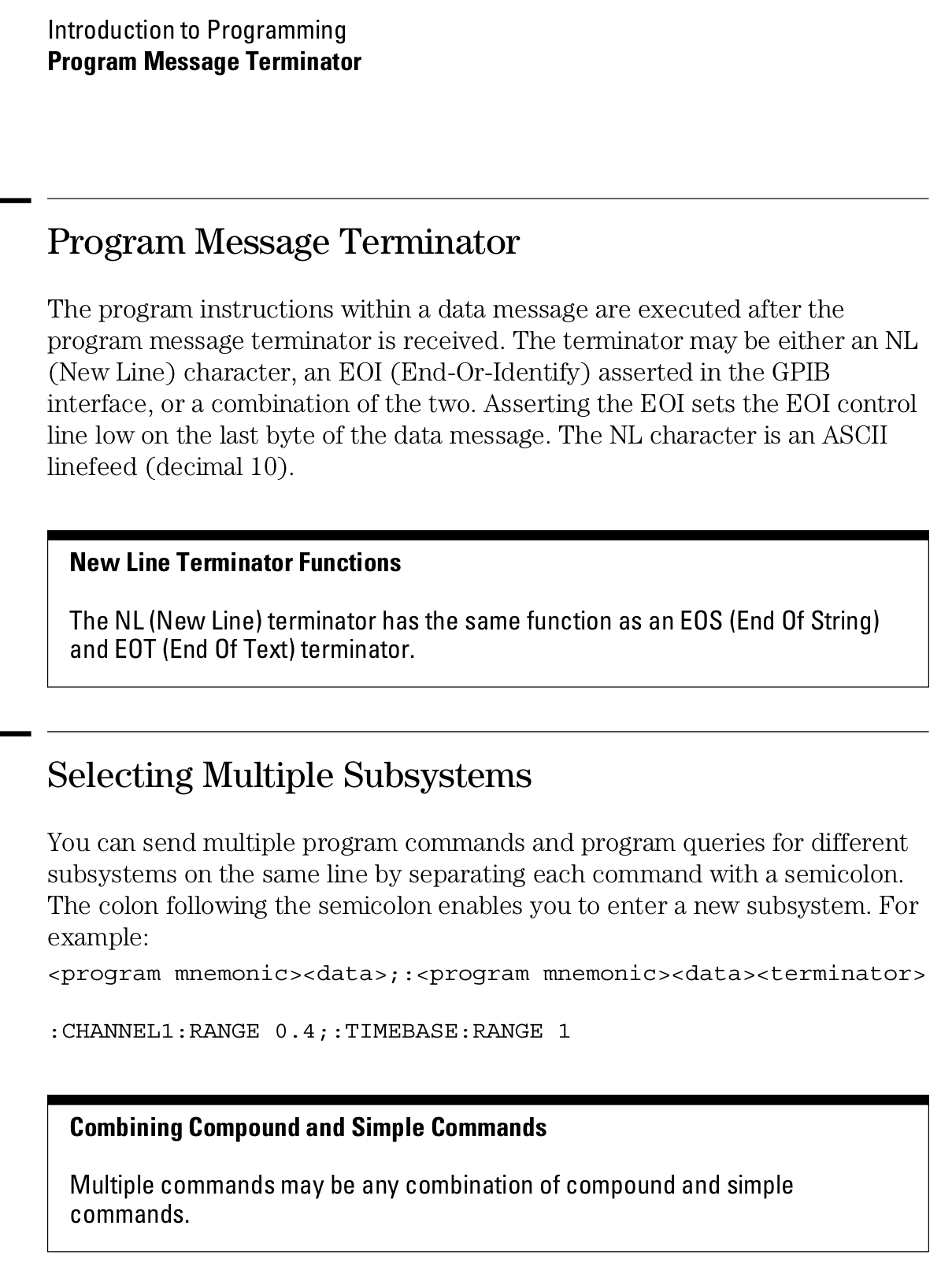
I discovered that the real problem was not in the interface but in the documentation (go figure, huh!). The terminator character must be, instead of a NL, a semicolon. The NL terminator is probably still valid for the GP-IB interface.
I have tested this setup at 19200 baud, “DTR” flow control on the scope side and a generic USB-Serial converter (Cypress semiconductor) plus a null modem cable and it worked just fine. The software on my PC is Windows 7, but I am running an Xubuntu Xenial under Virtualbox and did the tests using minicom.
Sending NLs did not seem to affect the communication at all but be aware that the error handling routines on the scope side are not the best, meaning that most probably after some errors or just one (which you will see emerge on the scope screen) you will need to reboot the scope to be able to communicate again. No big deal but it could be annoying.
This is a sample of a command sequence to measure the frequency of the calibrator connected to the Channel 1 input:
Let me know if it works for you, or if I can be of any help.
Which knocked me out of my chair!
Wow!
That’s the first time the scope’s serial output pin produced a different voltage in the last, uh, three decades! [grin]
You’re absolutely right about the command parser: it falls off the rails at the slightest provocation and leaves no suicide notes behind.
Gingerly following your technique, I found the scope’s serial interface must be in its “connected to computer” mode; the printer & plotter modes (not surprisingly) don’t respond to commands.
Even with that, I’m unable to get a consistent response to (what seem to be) correctly formatted commands. If I send some *RST; commands, eventually it’ll reset, but I sometimes can’t get anything back from status inquires like *SRE?; and so forth.
Sometimes, a linefeed (Ctrl-J) works as a terminator, sometimes it doesn’t. Even with a semicolon at the end of the command, it sometimes responds only after a Ctrl-J. Recovering from errors seems to require a random number of successive ; and linefeed characters.
What definitely doesn’t work: a normal carriage return + linefeed combination! I think that explains my complete lack of success many years ago, as I probably used a terminal program that automatically sent CR+LF at the end of each line.
However, it’s now doing something in response to serial commands, which it never did before.
The only way to use the interface will be with a (tediously debugged) program sending a preset command sequence and receiving a known series of responses. Hand-carving a series of commands just won’t work.
Gastón did a bit more poking around:
It seems that the implementation for the different oscilloscopes of the same family was different. This was to be expectable but I didn’t think it would be *so* different.
In my case, as said, linefeed does nothing at all. This weekend I will try (just for grins of course) to use linefeeds interspersed with the letters of a single command to see to what extent they are ignored.
In my opinion, the inconsistent response you get could have to do with the implementation of the interface on the computer side, or even marginal baud rate or jitter. I had to resort to the Xubuntu-within-Virtualbox-within-Windows7 just because I couldn’t get a consistent communication from Windows 7 alone from my “usual” laptop. I tried another laptop with Xubuntu as OS and the serial port worked only up to 9600 baud, and with some errors from time to time, shown as “Override error” and “RS232 Protocol Error” on the scope screen. From this ones, the oscilloscope did recover without problems. Parser ones in my case are fatal every time. They show as “Unknown Header” and that’s a death signal. The oscilloscope functionality, though, is not affected in any way.
Just as an aside, my HP 54659A interface uses a Philips SCN2661AC1A28 as UART.
I agree with you regarding to the way to use it is with a program that only sends the right sequence of commands and receives in turn a known series of responses. Back in the ’90s I worked with a functional level board tester which used several HPIB-managed instruments (HP3314 arbitrary waveform generator, two programmable power supplies), a couple others with VXI bus, among which there was a display-less version of an HP545xx oscilloscope. That beast was managed from an IBM PS/2 model 70 (a 486 based one) with National Instruments interface boards. Not a hobby setup in any way. Every single time I managed to send the wrong command to the oscilloscope, I had to reboot both the board tester rack and the PC… so the parser’s lack of humor is not exclusive of the 546xx series :).
Even with a fully debugged command sequence, sometimes the oscilloscope decided to act up… this last didn’t happen very often but when it did, it was extremely annoying for the tester operator as the sequence was a lengthy one (about 10 minutes per board) and when it failed, it meant sometimes half an hour of time lost, between recognition of a tester failure (and not simply a board that required multiple test retries and thus took longer than usual), reboot of both instruments rack and computer, and rerun.
And a followup which may discourage all but the stout of heart:
To add to the general confusion, I tried with Ctrl-J instead of a semicolon, and the commands are accepted too. It seems that my tty terminal setup is not as good as I thought it was.
The semicolon, from what I have been reading, is a command separator within a line and perhaps that is why it is accepted as readily as the linefeed. I did test sending newlines between the characters and I got a “Syntax Error” in the scope screen from which the only way to recover was an oscilloscope reboot.
Page 1-12 from the Programmer’s Guide (54600-97032) may be of interest (clicky for more dots):
A laptop-style power brick supplies 24 V for the MPCNC’s stepper motors, but I didn’t want it wandering around on the Basement Laboratory floor and getting in trouble, so a pair of brackets seemed in order:
Power Supply Brick Mount – trial fit
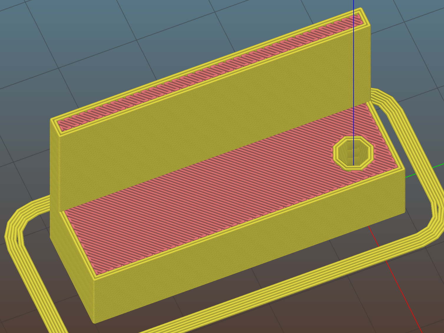
They build flat on their backs to avoid support material:
Power Supply Brick Mount – Slic3r
The nicely rounded corners produce a very thin line of plastic on the first layer, so the model now has thicker base plates to improve the situation. A set of mouse ears would keep the tips pasted to the glass.
This file contains hidden or bidirectional Unicode text that may be interpreted or compiled differently than what appears below. To review, open the file in an editor that reveals hidden Unicode characters.
Learn more about bidirectional Unicode characters
This will eventually end up on a board supporting the GRBL controller box:
Control Box – Connector Mount – Slic3r
It’s a direct cut-n-paste descendant of the old NEMA motor mount.
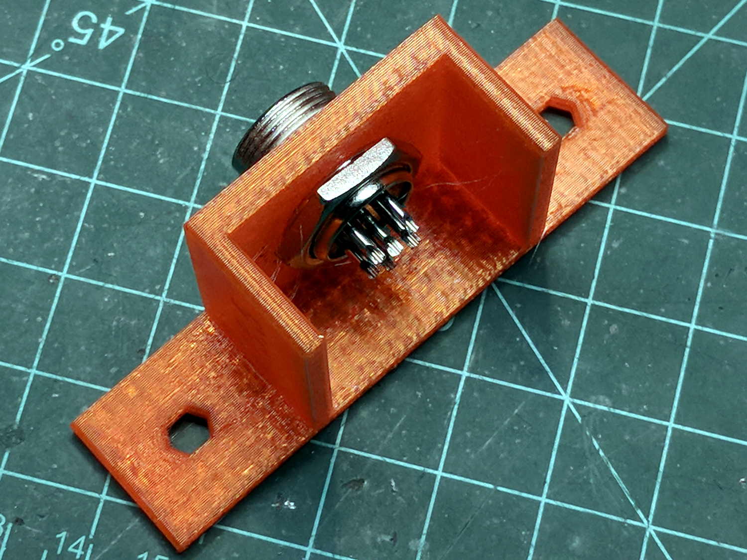
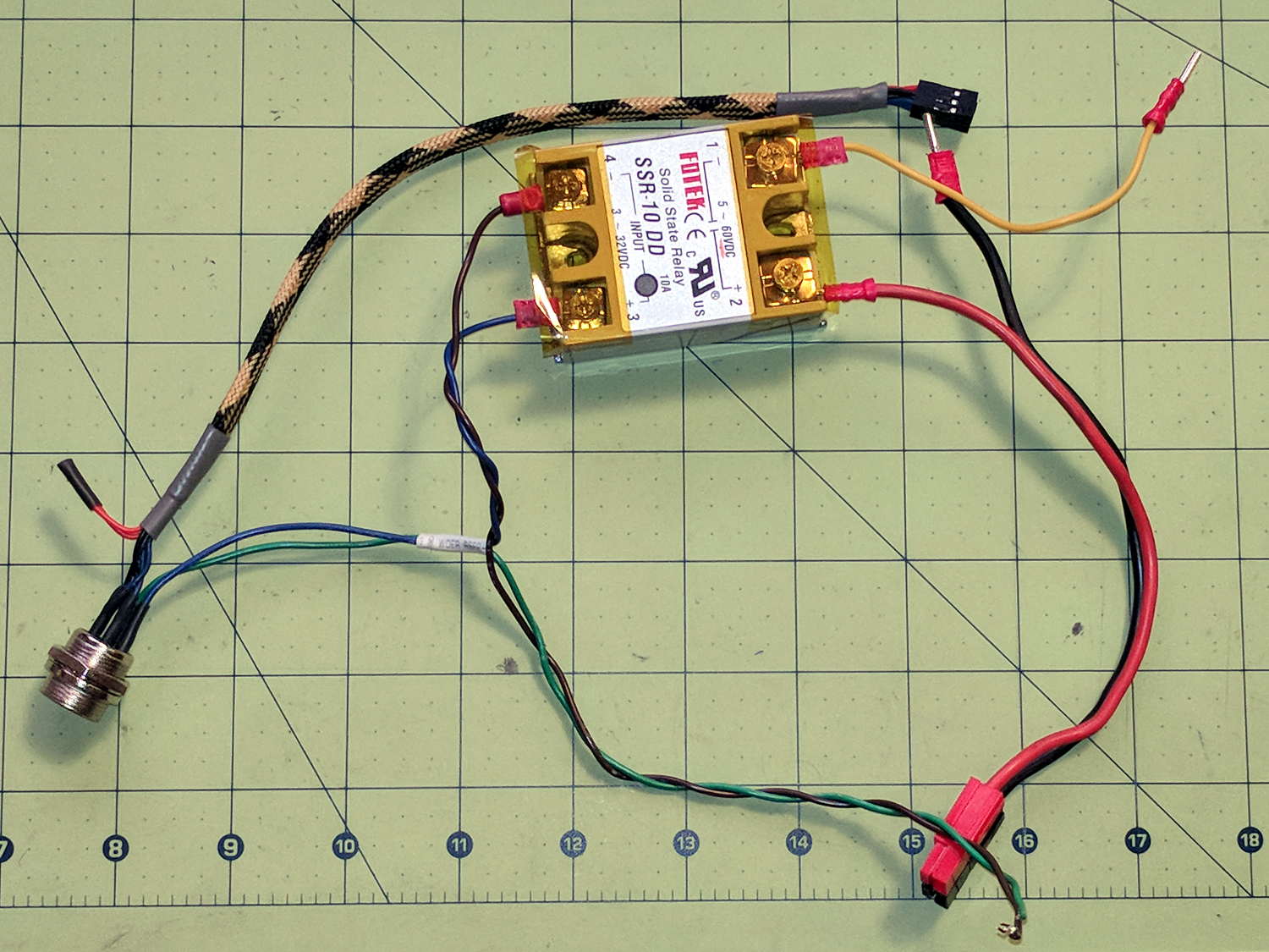
The nut threads onto the connector behind the bulkhead, so you must either wire it in place or make very sure you can feed all the terminations through the hole:
Connector Mount
Given the previous hairball, I think in-situ soldering has a lot to recommend it:
This file contains hidden or bidirectional Unicode text that may be interpreted or compiled differently than what appears below. To review, open the file in an editor that reveals hidden Unicode characters.
Learn more about bidirectional Unicode characters
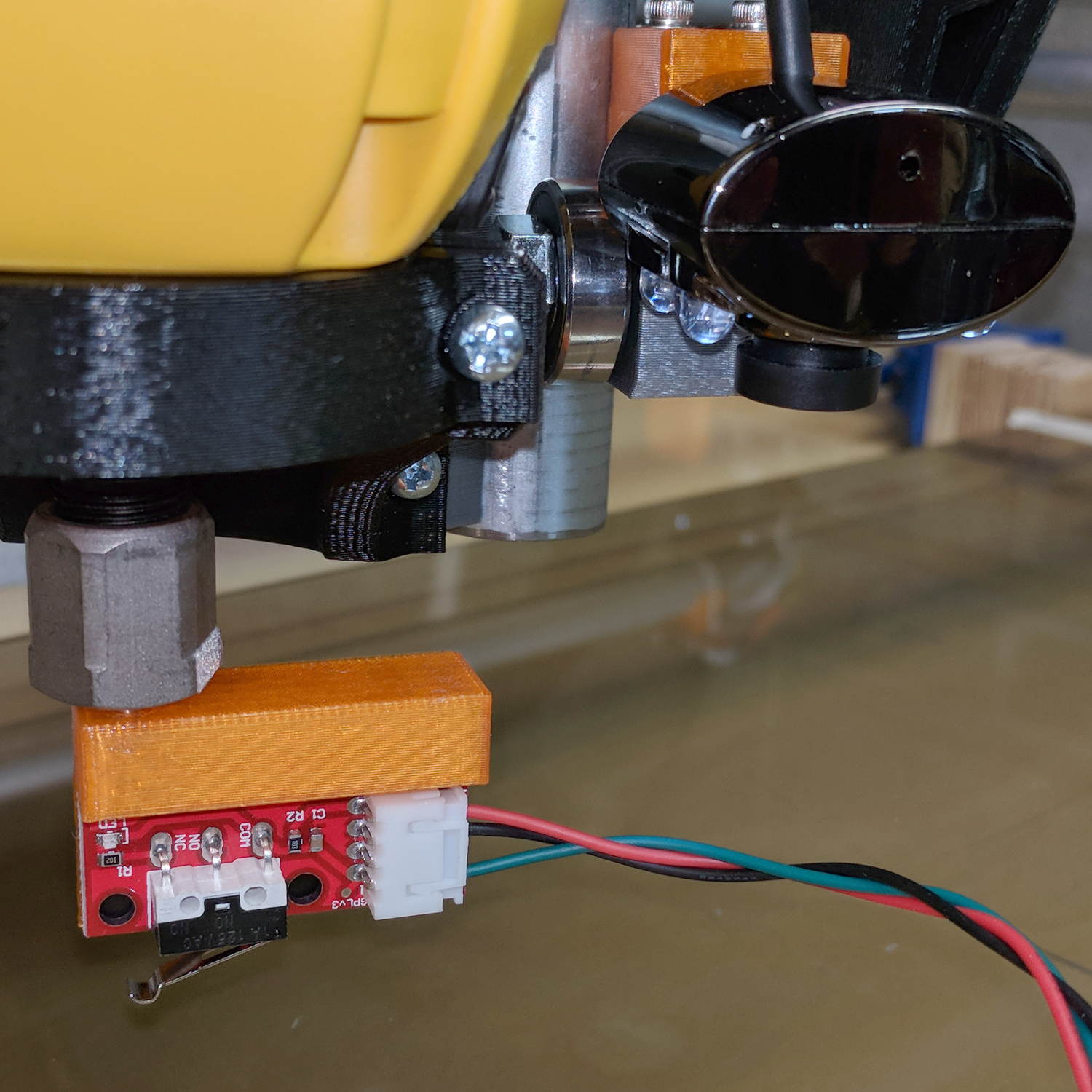
The DW660 collet grabs a length of 1/8 inch drill rod jammed into a hole positioned to put the switch actuator directly in line with the spindle axis when it trips the switch, so as to measure a known and useful location:
Z Axis Height Probe – MBI endstop – Slic3r
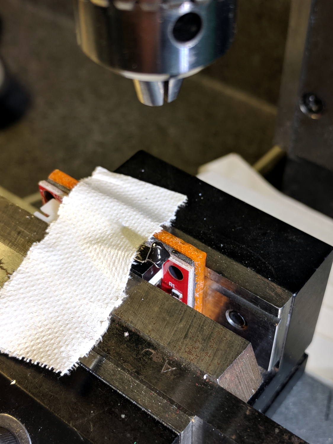
After mulling things over for a while, I fired up the Sherline, drilled a #54 hole in the actuator, and epoxied a 3/32 inch bearing ball in the hole:
MPCNC – Endstop Z probe – bearing
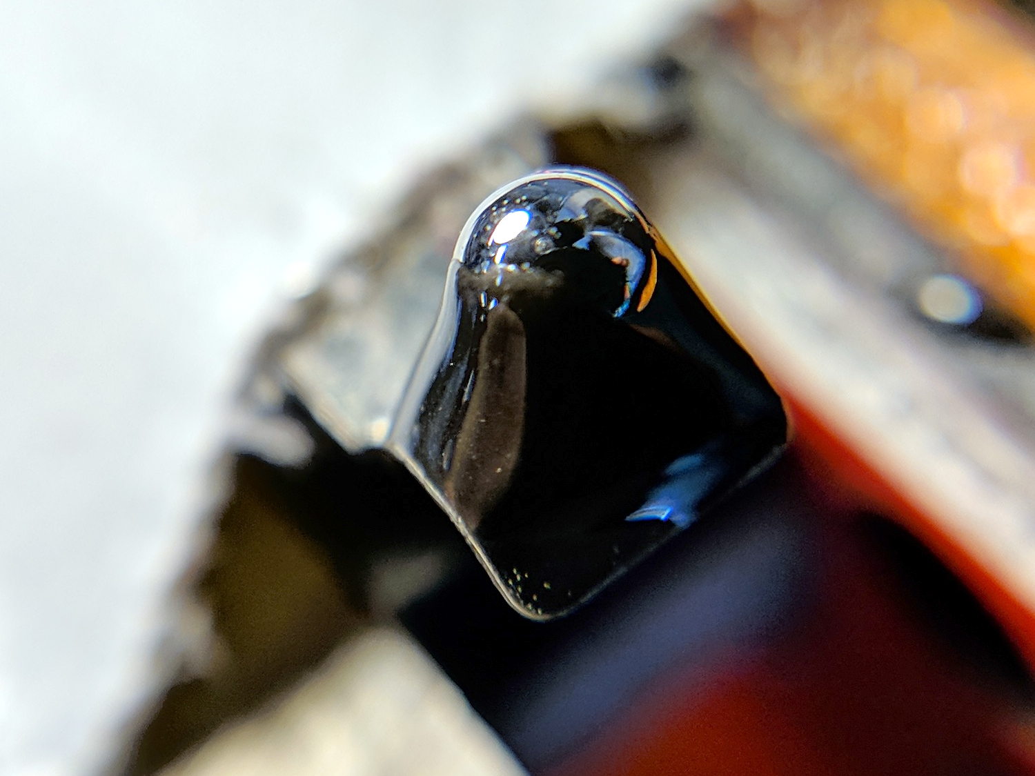
A #54 drill hole is half the diameter of the ball and, with a bit of luck, enough of the ball will stick through into the epoxy on the underside for a good grip:
MPCNC – Endstop Z probe – bearing – detail
The general idea is to convert the stamped steel actuator into a single, albeit not particularly sharp, contact point that can glide over the platform / PCB / sheet-of-whatever to measure the surface. The actuator pivots as it depresses, so the ball must slide horizontally just a bit. I prefer a rod-in-tube probe poking a linear button switch, but those weren’t getting me anywhere.
This file contains hidden or bidirectional Unicode text that may be interpreted or compiled differently than what appears below. To review, open the file in an editor that reveals hidden Unicode characters.
Learn more about bidirectional Unicode characters
Because the OLED driver came from the pip package manager, not the Raspberry Pi’s system-level apt package manager, it (or they, there’s plenty of code under the hood) don’t get updated whenever I do system maintenance. The doc says this should do the trick:
sudo -H pip install --upgrade luma.oled
However, it turns out the new version has a slightly longer list of pre-requisite packages, causing the update to go toes-up at a missing package:
Could not import setuptools which is required to install from a source distribution.
Please install setuptools.
So update (or install, for the new ones) the missing pieces:
Doing so produced a backwards-compatibility error in my Python code:
... change ...
from luma.core.serial import spi
... into ...
from luma.core.interface.serial import spi
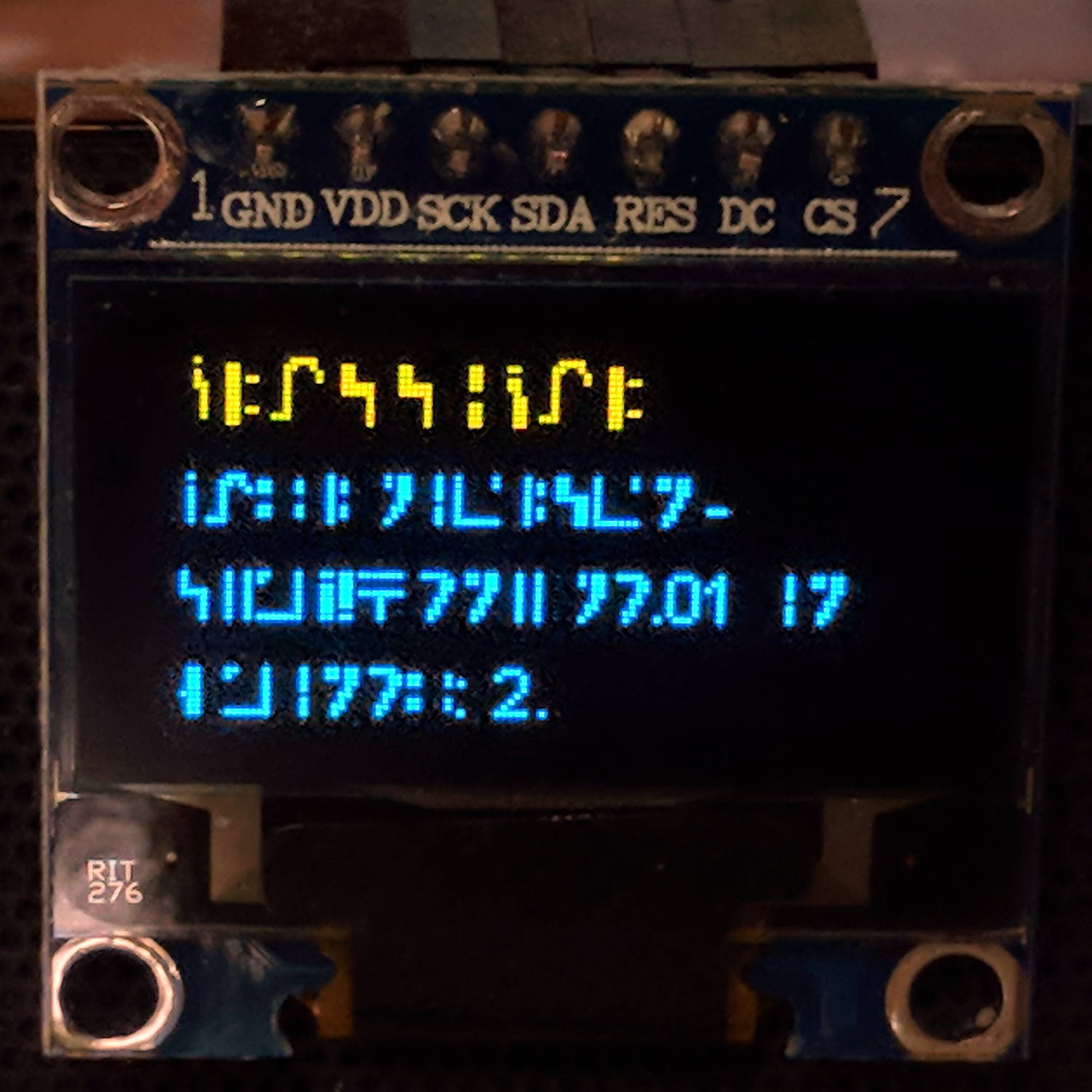
The motivation for all this fuffing and fawing came from watching some OLEDs wake up completely blank or become garbled in one way or another. Evidently, my slower-speed SPI tweak didn’t quite solve the problem, although it did reduce the frequency of failures. I have decided, as a matter of principle, to notembrace the garble.
Soooo, let’s see how shaking all the dice affects the situation.
It’s entirely possible the OLED controllers don’t quite meet their specs, of course, or have begun deteriorating for all the usual reasons.