Given a camera running Xiaomi Dafang Hacks software, you can set up motion-triggered image capture and save the images either locally or on an FTP server. The latter makes sense, as it automatically plunks the images where they’re more generally available.
Define the FTP server parameters in config/motion.conf:
# Configure FTP snapshots and videos
ftp_snapshot=true
ftp_video=false
ftp_video_duration=10
ftp_host="192.168.1.10"
ftp_port=21
ftp_username="ftp-user-id"
ftp_password="secret-password"
ftp_stills_dir="Cam4"
ftp_videos_dir="Cam4"
The FTP server should have the Cam4 directory in place and shared for read-write access before attempting to plunk files therein. Ahem.
The camera’s Services menu leads to the motion configuration page:
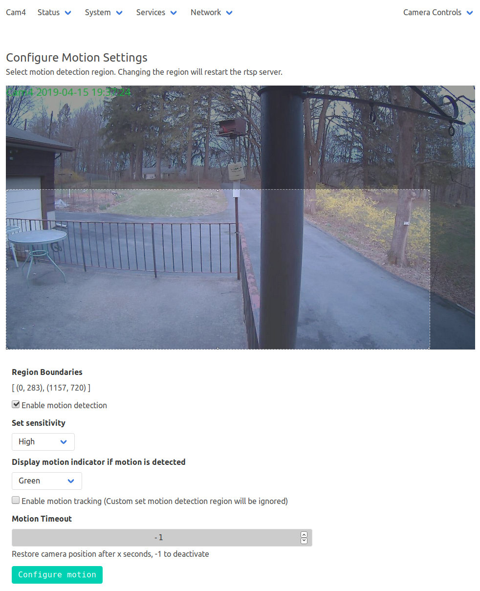
Limiting the detection region to the lower-left corner cuts out all the waving-in-the-breeze foliage in the yard, while covering the driveway. High sensitivity detects squirrel-sized objects in the foreground, although your mileage will certainly differ.
The camera seems rate-limited at 5 s/image, which may come from FTP transfer overhead; I don’t know if the code includes a built-in delay or if it just works like that. The NAS drive requires upwards of 7 s to spin up if it hasn’t been used for a while, but afterwards the transfers don’t take that long.
Mounting the NAS drive’s CIFS shared directory from my desktop PC works as before:
sudo mount -v -o rw,credentials=/root/.nas-id,vers=1.0,uid=ed -t cifs //192.168.1.10/Cam4 /mnt/partThen view / edit / delete images as needed:

The camera has built-in IR LEDs, but they’re nowhere near powerful enough to illuminate the entire yard.
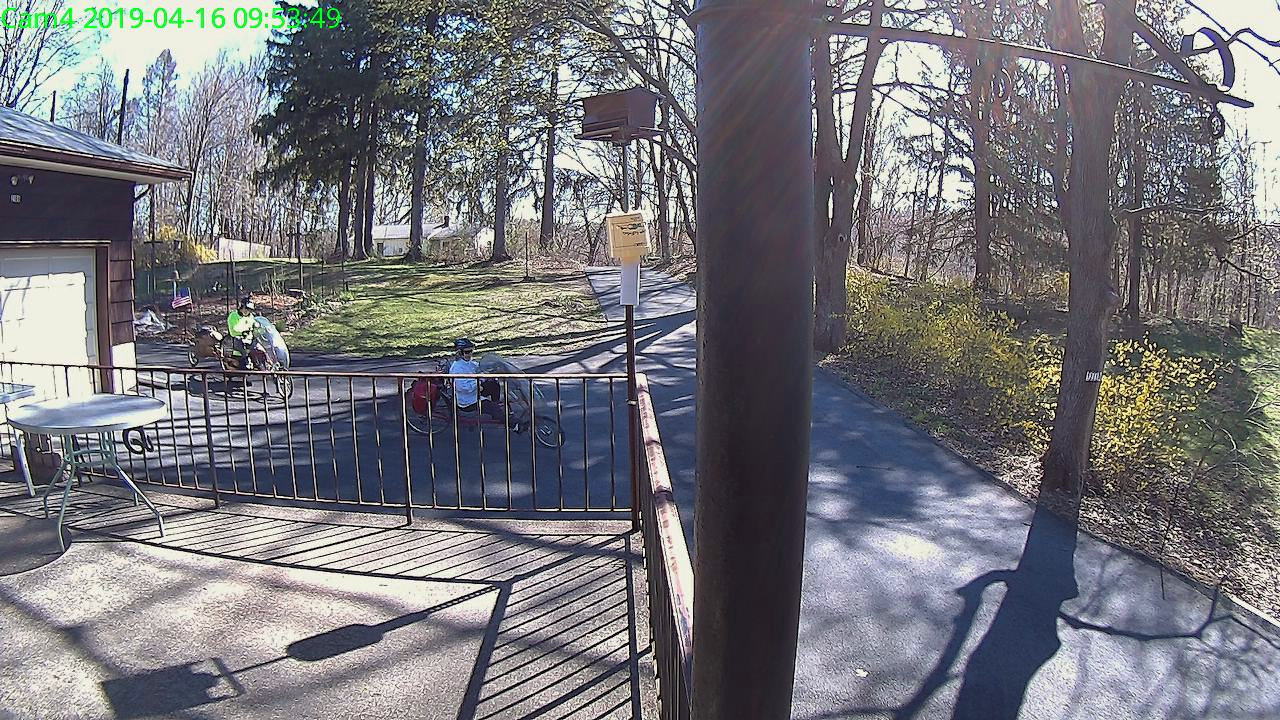
Motion detection works better in daylight:
Unlike the original Wyze firmware, the Xiaomi Dafang Hacks firmware & software keep all the images & metadata within my network and under my control.