
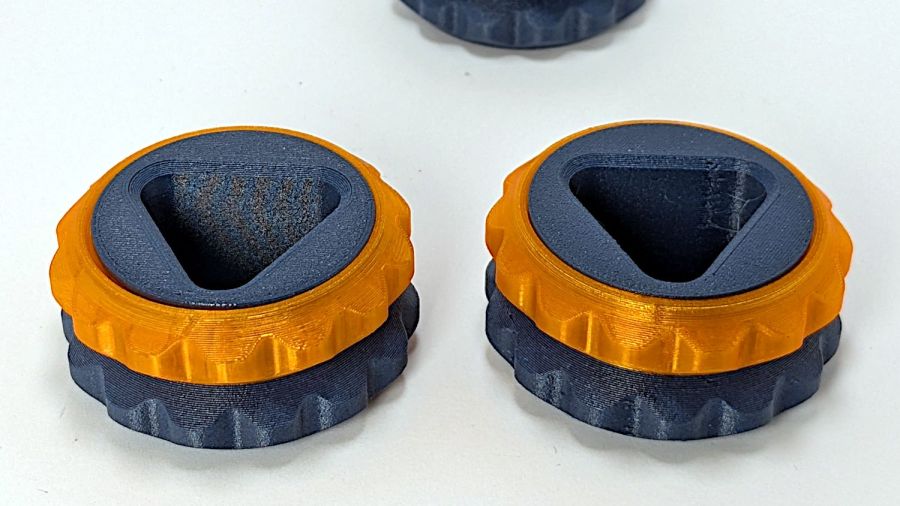
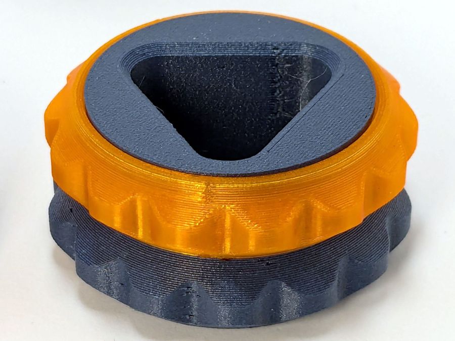
The HQ Sixteen consumes thread at a prodigious rate, so it’s set up for large thread cones. Mary sometimes uses ordinary thread spools (leftovers from sewing projects) for short practice sessions and wanted an adapter to hold the little things in place:
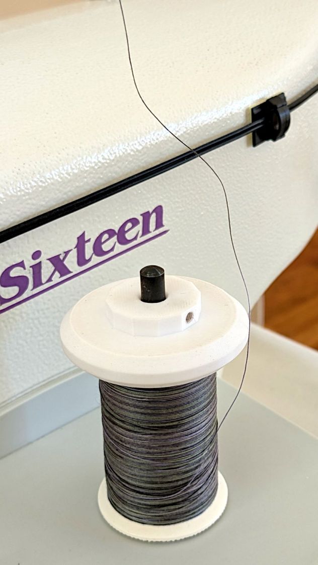
Those of long memory should recall previous adapters for both sizes and their notes about how thread should peel off spools & cones. I considered an adapter with a horizontal spool axis, but contemporary machines apparently don’t bother with such niceties. We may need a right-angle adapter to let the thread pull off from the side, but we’ll start simple and fix it if needs be.
Update: It needed fixing.
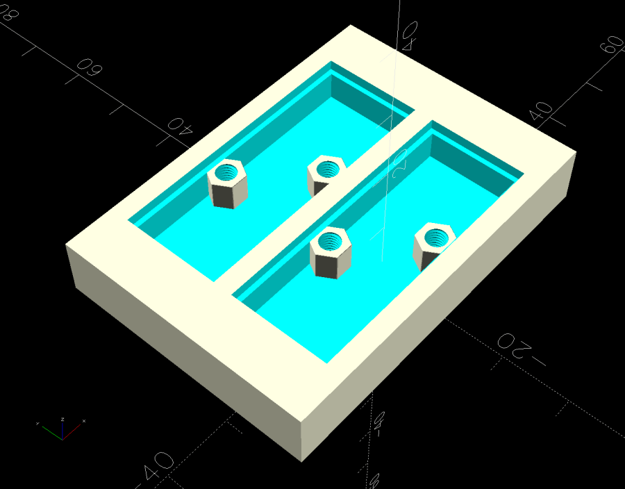
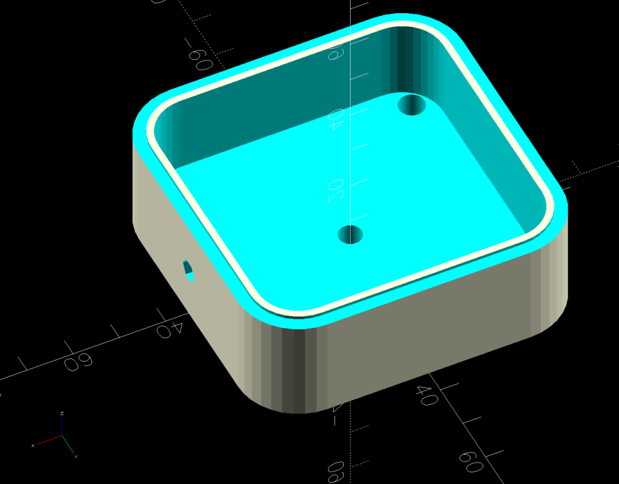
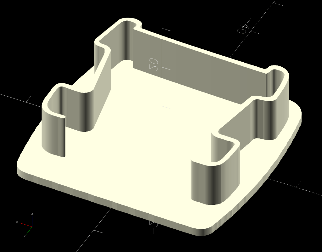
The solid model looks about like you’d expect:

The small crosswise hole in the hub gets an M3 setscrew pushing a rubber pellet slightly into the central bore for a friction fit. The OpenSCAD code can distribute any number of such holes, but one seemed entirely adequate.
The code shrinkwraps a hull() around two cylinders to create the tapered sides, thus giving the thread less surface to drag across. I have PrusaSlicer set to produce scarf joints around the perimeter and the edges came out surprisingly smooth, with only one rough spot requiring deft Xacto knife work. It’s made from white PETG for a smoother finish than PETG-CF.
The OpenSCAD code consists mostly of constants defining the various physical measurements and a few lines assembling the model:
// HQ Sixteen - thread spool adapter
// Ed Nisley - KE4ZNU
// 2025-01-21

include <BOSL2/std.scad>

/* [Hidden] */

PinOD = 0.25*INCH;

RingOD = 50.0;      // outer perimeter of thread ring
RingEdge = 3.0;     // height of ring edge & tapers
RingAngle = 45;     // upper & lower tapers wrt vertical

RingOAH = 3*RingEdge;

ScrewOD = 2.5;      // tap for setscrew compressing rubberdraulic piston
NumScrews = 1;

HubOD = 25.0;
HubThick = 2*ScrewOD;
HubSides = 12;

ScrewCL = RingOAH + HubThick/2;

AdapterOAH = HubThick + RingOAH;

Protrusion = 0.1;

NumSides = 12*3*4;   // smooth outer perimeter

//----------
// Build it


difference() {
    union() {

        hull() {
            linear_extrude(RingOAH)
                circle(r=RingOD/2 - RingEdge*tan(RingAngle),$fn=NumSides);

            up(RingEdge)
                linear_extrude(RingEdge)
                    circle(d=RingOD,$fn=NumSides);
        }

        linear_extrude(HubThick + RingOAH)
            rotate(180/HubSides)
                circle(d=HubOD,$fn=HubSides);

    }

    down(Protrusion)
        rotate(180/HubSides)
            cylinder(d=PinOD,h=2*AdapterOAH,$fn=HubSides);

   for (i=[0:NumScrews-1]) {
        a = i*360/NumScrews;
        zrot(a)
            up(ScrewCL)
                yrot(90)
                    zrot(180/6)
                        cylinder(d=ScrewOD,h=HubOD,$fn=6);
    }

}
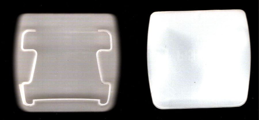
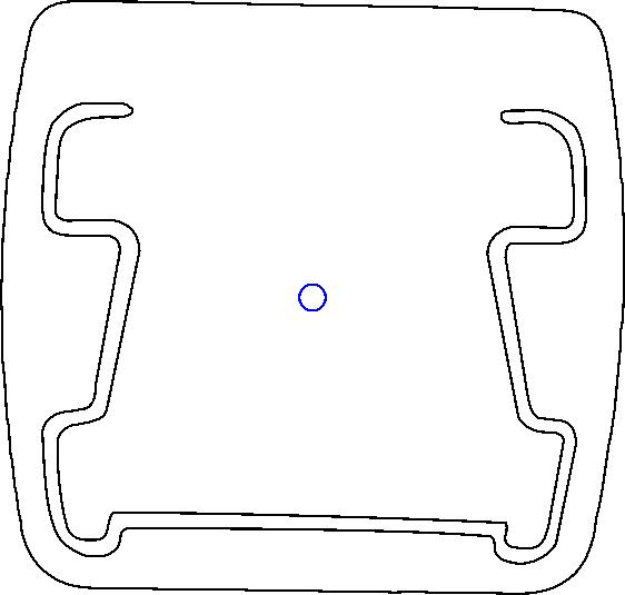
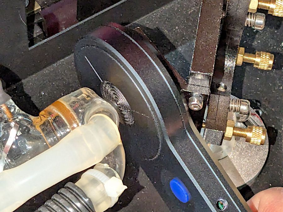
Putting the adapter in the light box revealed the same problem as photographing white dogs in snowstorms:
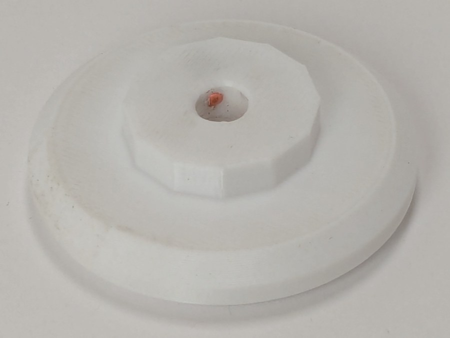
There was no contrast to be enhanced anywhere, although the rubber pellet definitely stands out.


