Ed Nisley's Blog: Shop notes, electronics, firmware, machinery, 3D printing, laser cuttery, and curiosities. Contents: 100% human thinking, 0% AI slop.
Category: Science
If you measure something often enough, it becomes science
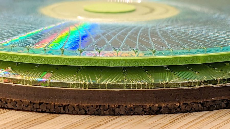
A bit less than a year ago I engraved Guilloche patterns on a stack of DVDs, stuck foam on their data sides, and defined the result to be coasters:
Laser cut CDs – Foam vs MDF-cork backing – detail
Perhaps unsurprisingly, those grooves turned out to be excellent stress raisers, to the extent that the two most-used coasters (we’re not talking heavy use) have developed cracks:
Laser-engraved DVD A – stress cracks
The parallel lines are part of the logo / pattern / design printed on the label side of the disc, which seems to have wrinkled after being glued to the foam layer. The cracks radiate outward from the laser-scarred zone around the hub.
The other one is worse:
Laser-engraved DVD B – stress cracks
None of the discs glued to rigid backing plates show anything more than minor cracks, so I think a combination of stress raising and slight flexing is really bad for cheap coaster-like objects.
No great loss, easily outweighed by knowing what not to do next time …
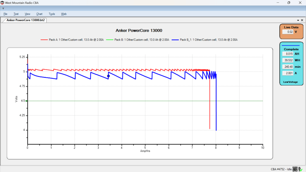
After five years of powering the action cameras on our Tour Easy recumbents, the pair of Anker A1215 PowerCore 13000 USB power banks have about 8 A·hr of capacity with a 2 A load after a full charge:
Anker PowerCore 13000 – 20204-07-26
It seems I did not test them on arrival, so I have no idea what their original capacity might have been, but I’m certain it wasn’t the 13 A·hr implied by their name.
The sawtooth voltage output looks like the internal controller picks a constant boost (or buck) ratio based on the battery voltage, then adjusts it when the output voltage falls below the lower limit. You can imagine it desperately boosting the ratio as the battery voltage falls off a cliff near the end of the curve.
I have no idea why the two packs behave so differently, although the voltages are certainly within ordinary USB limits.
They’ll continue powering the camera on my bike for a while, after which I’m sure they’ll come in handy for something …
The upper one has a coating of clear rattlecan paint and looks much the better for it. The lower one is bare, but also suffered greatly from being folded and tucked through itself, so it started in worse condition.
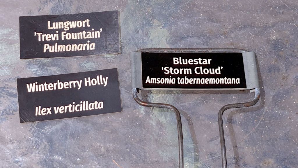
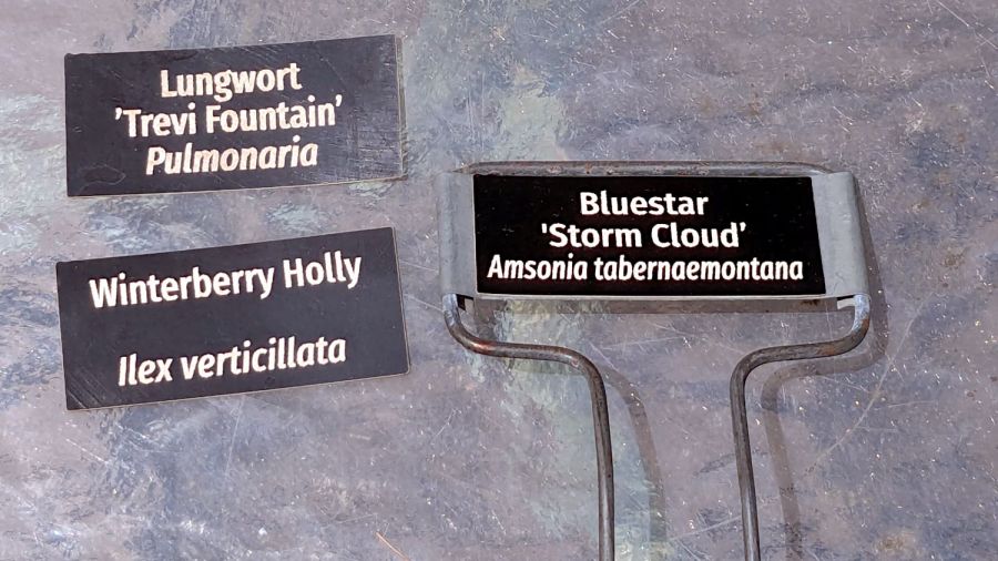
Perhaps the paper will work better when stuck to metal plant label stakes, although I suspect the adhesive sheet will fail first:
Laser test paper – small plant labels
Those are random names; Mary tells me the proper label format has the Latin nomenclature on the first line.
They’re now out on the patio for observation.
For whatever it’s worth, my fascination with this paper boils down to “it’s cheaper than Trolase” for applications not requiring archival quality and duration. If it lasts Long Enough, that’ll be Good Enough.
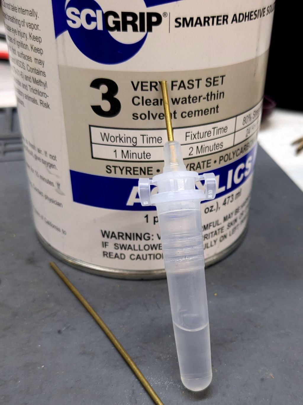
This seemed like a good idea for dispensing small drops of acrylic solvent while gluing spiders together:
COVID test Buffer Extraction Tube – adhesive hack
It’s the Buffer Extraction Tube from a COVID-19 rapid test kit with a short brass tube jammed in its dropper tip. The longer brass tube let me suck that dose of solvent into the tube without any of the hassle required to pour the liquid from a big can into a little tube.
Tell me you didn’t save those things because you thought they didn’t look like they might come in handy for something.
Well, that turned out to be a Bad Idea™, because whatever plastic that tube is made out of cracks when exposed to the hellish mixture in SCIGRIP #3 solvent adhesive. The tube didn’t dissolve or melt, it just cracked when you (well, I) squeezed the sides.
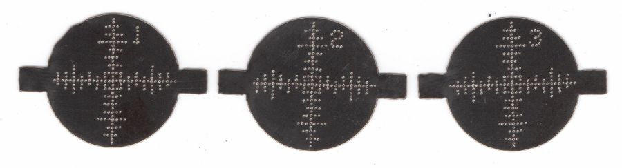
The dots just barely punch through the back side (open in a new tab & zoom for more dots):
Test paper – target patterns back side- 2024-07-03
The plastic coating chars and buckles with each pulse, but remains in place:
Test paper – 2 shot – uncleaned – 2024-07-03
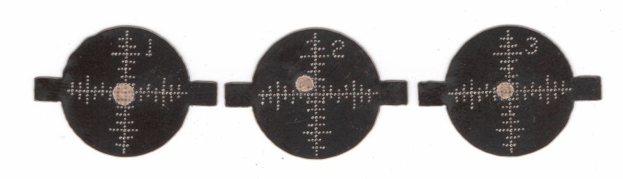
Wiping the surface removes the loose coating / ash / debris to expose the underlying charred paper core:
Test paper – 2 shot – wiped – 2024-07-03
Those are two pulses marking the ends of each axis, so the machine remains well aligned after the fourth-quarter tweak.
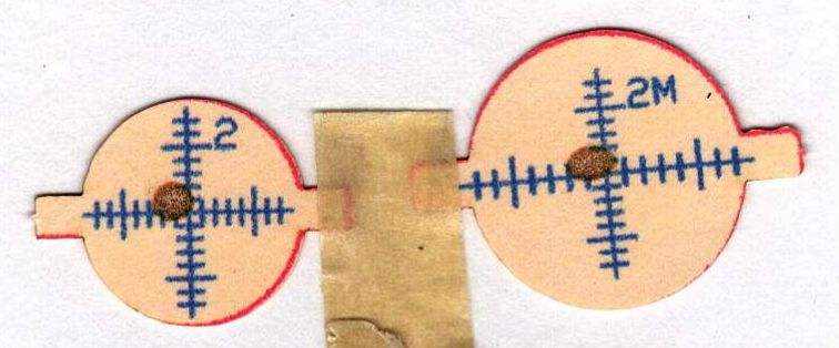
A single pulse shows the beam has a nice round shape with well-defined edges:
Test paper – 1 shot – wiped – 2024-07-03
In principle, the beam should be more intense toward the middle, but I suspect that’s beyond the paper’s ability to resolve the energy; the beam either burns through the coating or it doesn’t. In all those targets, the back surface of the paper remains undamaged.
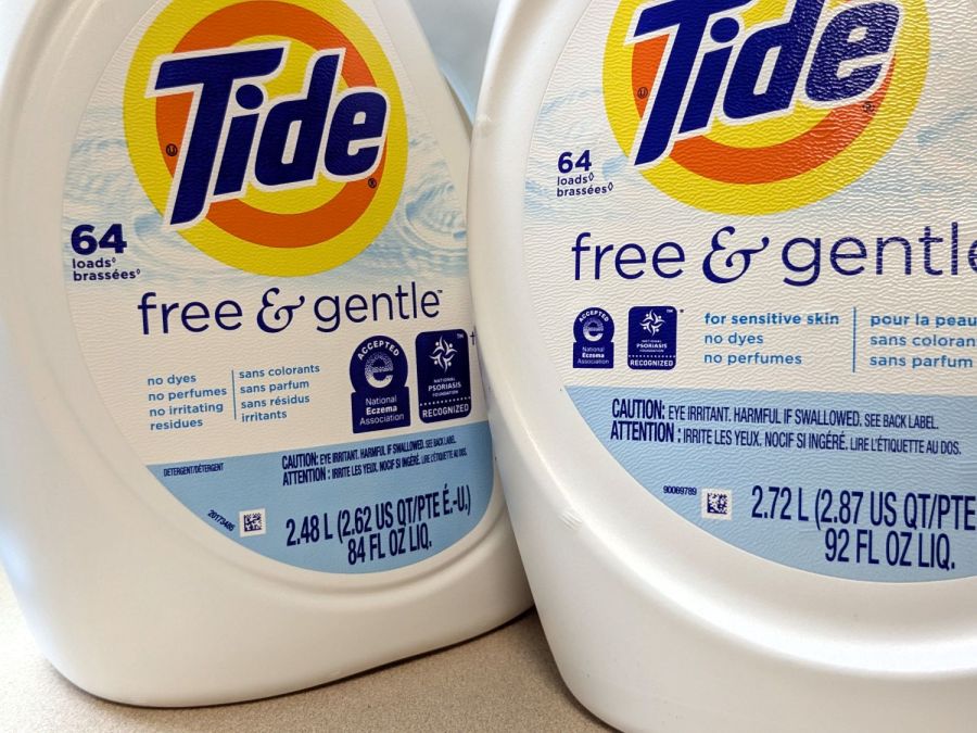
The most recent Tide HE Laundry Detergent bottles seemed smaller than the one we were about to empty and, indeed, they were:
Tide HE shrinkflation – bottle labels
Call it 9% smaller, based on the volume in liters. I suspect the price was also 9% higher, but that would require more digging in the file cabinet than seems justified.
Note that both bottles claim “64 loads”, each with an asterisk (well, a lozenge ◊ symbol) explained on the label:
Tide HE shrinkflation – new load bars
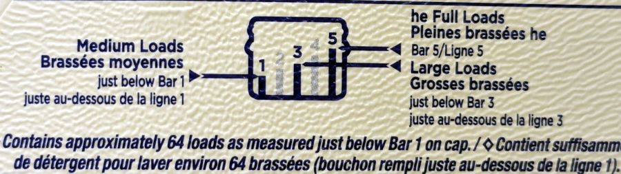
That’s the new chart. The old chart was more explanatory:
Tide HE shrinkflation – old load bars
Note the “just below Bar 1 on cap” weasel wording. The term “meniscus” enters the chat, although laundry detergent doesn’t have much in the way of surface tension.
One might reasonably assume the bars on the new cap have gotten shorter, so that the volume of detergent used for each load would be smaller.
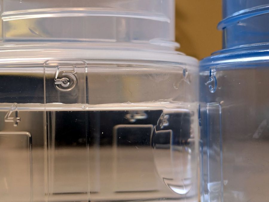
One would be wrong:
Tide HE shrinkflation – cap capacity marks
The blue cap on the right is one we’ve been using for the last few years, because I put black tape at the level of the first bar to match our “Medium” loads. I cannot imagine how much dirt would require filling the cap to Bar 5.
The clear cap on the left is the new cap. I filled the blue tap to the top of Bar 5 with water and poured it into the clear cap, where it comes about 3/4 of the way to the top of the new Bar 5. Evidently, the amount of detergent required to get grubby clothes clean has increased by 33%.
The old cap holds just shy of 4 fluid ounces to the top of Bar 5:
Tide HE shrinkflation – old cap bar 5 capacity
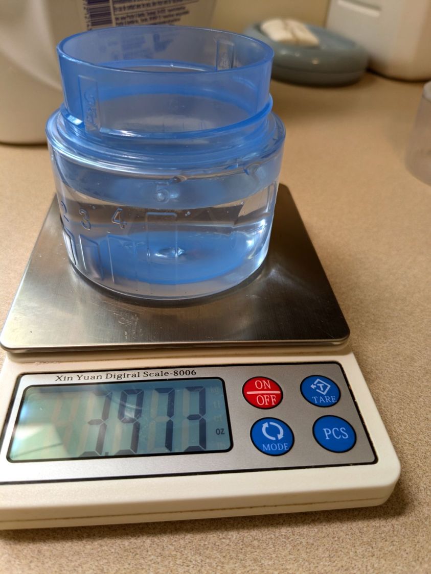
The new cap holds 5.5 fluid ounces to the top of its Bar 5:
Tide HE shrinkflation – new cap bar 5 capacity
If you have really crusty clothing, you’re now using 36% more detergent per load.
The obvious arithmetic shows the old bottle holds 23 “Bar 5” loads and the new bottle holds 15.
To the limit of my measuring ability, both caps hold 1.3 fluid ounces to the top their respective Bar 1 levels. I cannot vouch for the “just below” level, but I suspect more accurate measurements would show the new caps have slightly lower volume at that level, juuust enough to make the “64 loads” weasel wording come out right.