A critter made off with our battered plastic rain gauge, so I set up an Ambient Weather WS-5000 station to tell Mary how much rain her garden was getting. I added the Official Bird Spike Ring around the rain gauge to keep birds off, but robins began perching atop the anemometer while surveying the yard and crapping on the insolation photocell.
After a few false starts, the anemometer now has its own spikes:
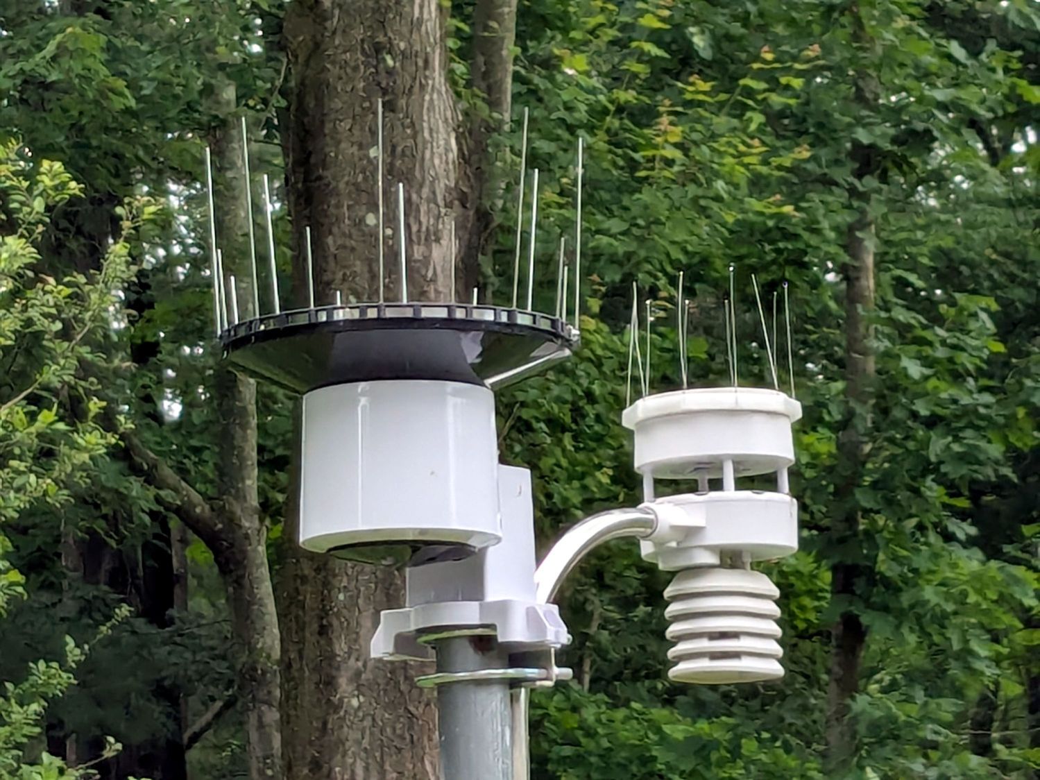
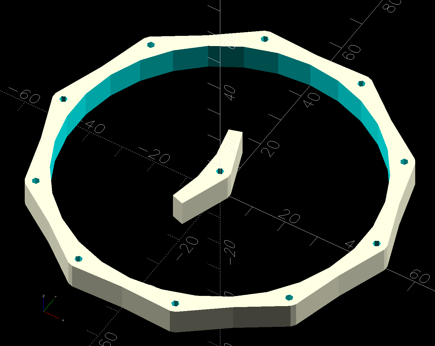
It’s a snugly fitting TPU ring:
The spikes are Chromel A themocouple wire, because a spool of the stuff didn’t scamper out of the way when I opened the Big Box o’ Specialty Wire. As you can tell from the picture, it’s very stiff (which is good for spikes) and hard to straighten (which is bad for looking cool).
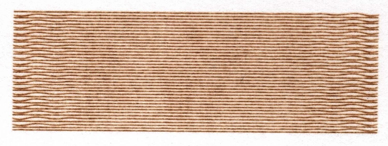
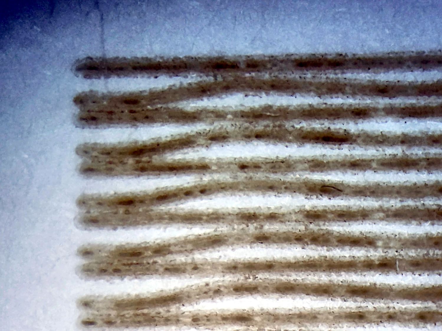
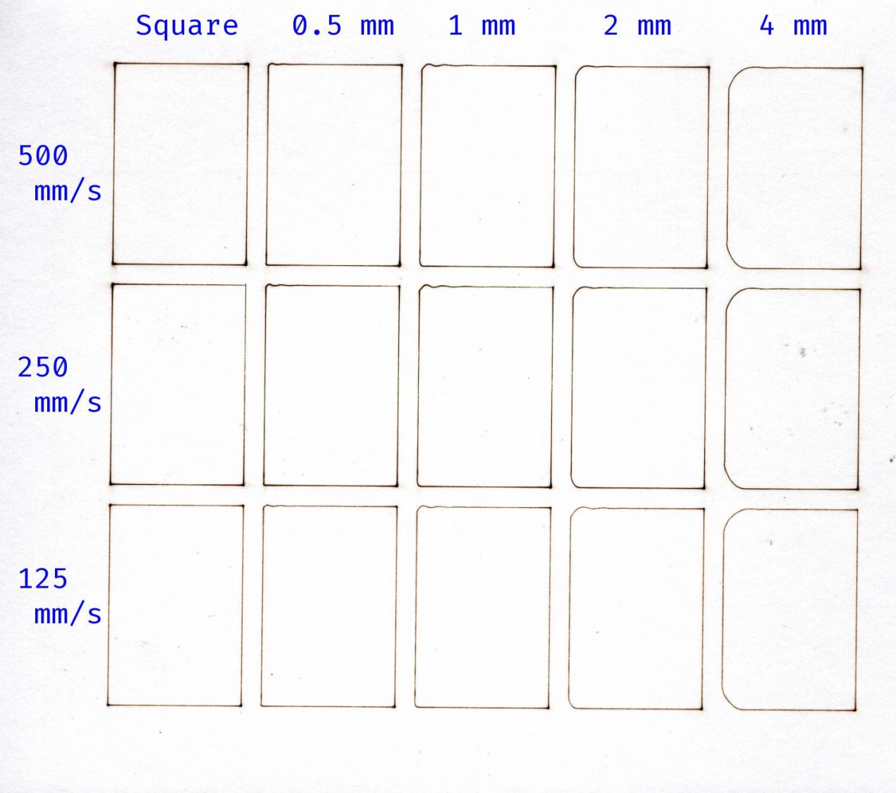
The shape in the middle is a hole diameter test piece. Next time around, I’ll use thicker 14 AWG copper wire:
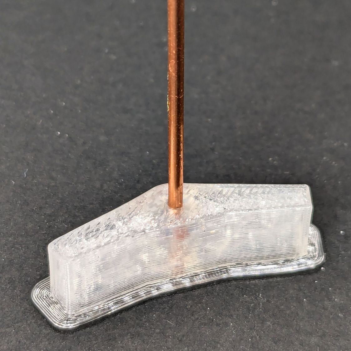
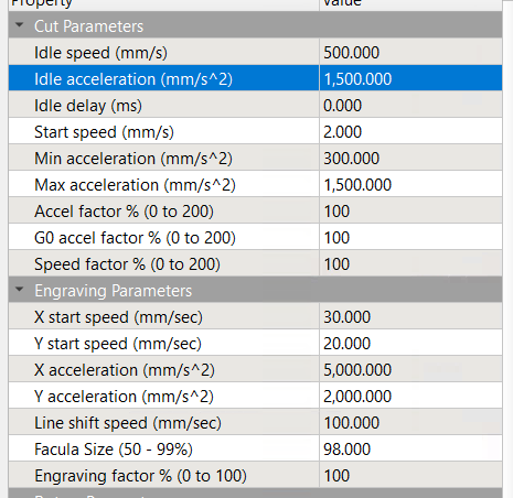
The test piece showed I lack good control over the TPU extrusion parameters on the Makergear M2, as holes smaller than about 2 mm vanish, even though the block’s outside dimensions are spot on. This application wasn’t too critical, so I sharpened the wire ends and stabbed them into the middle of the perimeter threads encircling the hole.
Now we’ll discover how TPU survives weather.
The OpenSCAD source code as a GitHub Gist:
| // Ambient Weather – Ambient Weather WS-5000 anemometer bird spike ring | |
| // Ed Nisley – KE4ZNU | |
| // 2025-06-09 | |
| include <BOSL2/std.scad> | |
| Layout = "Show"; // [Show,Build,Slice] | |
| /* [Hidden] */ | |
| HoleWindage = 0.2; | |
| Protrusion = 0.1; | |
| ID = 0; | |
| OD = 1; | |
| LENGTH = 2; | |
| SpikeOC = 30.0; // straight-line distance between spikes, OEM = 35 | |
| WallThick = 4.0; | |
| BandID = 3.5*INCH – 0.5; // = OD of weather station | |
| BandOD = BandID + 2*WallThick; | |
| BandHeight = 8.0; | |
| SpikeOD = 1.7 + HoleWindage; // wire diameter | |
| SpikeWall = 2.0; // around wires | |
| SpikeBCD = BandOD; | |
| MountOD = SpikeOD + 2*SpikeWall; | |
| NumSpikes = ceil(PI*BandOD/SpikeOC); // need integral number of spikes | |
| SpikeAngle = 360/NumSpikes; | |
| NumSides = 3*NumSpikes; | |
| echo(SpikeAngle=SpikeAngle); | |
| echo(NumSpikes=NumSpikes); | |
| //———- | |
| // Define Shapes | |
| module Slice() { | |
| difference() { | |
| hull() { | |
| pie_slice(h=BandHeight,d=BandOD,$fn=NumSides,ang=SpikeAngle,spin=-SpikeAngle/2,anchor=BOTTOM); | |
| right(SpikeBCD/2 – MountOD/2) | |
| cyl(h=BandHeight,d=MountOD,realign=true,anchor=LEFT+BOTTOM,$fn=2*6); | |
| } | |
| down(Protrusion) { | |
| cyl(h=BandHeight + 2*Protrusion,d=BandID,$fn=NumSides,circum=true,realign=true,anchor=BOTTOM); | |
| right(SpikeBCD/2) | |
| cyl(h=BandHeight + 2*Protrusion,d=SpikeOD,$fn=6,circum=true,realign=true,anchor=BOTTOM); | |
| } | |
| } | |
| } | |
| module SpikeRing() { | |
| for (i=[0:NumSpikes-1]) | |
| zrot(i*SpikeAngle) | |
| Slice(); | |
| } | |
| //———- | |
| // Build things | |
| if (Layout == "Slice") { | |
| Slice(); | |
| } | |
| if (Layout == "Show") { | |
| left(SpikeBCD/2) | |
| Slice(); | |
| SpikeRing(); | |
| } | |
| if (Layout == "Build") { | |
| SpikeRing(); | |
| } |