Ed Nisley's Blog: Shop notes, electronics, firmware, machinery, 3D printing, laser cuttery, and curiosities. Contents: 100% human thinking, 0% AI slop.
Category: Science
If you measure something often enough, it becomes science
Looking up their NDC number helps translate the bullshit Latinesque nomenclature:
Glandula Suprarenalis Suis = boar adrenal glands
Thyroidinum = cow thyroid glands
Somatropin = human growth hormone
They’re exceedingly proud of that NDC number, touting “SOMADERM Gel is the only transdermal, FDA registered product”. Indeed, it’s registered, about which the FDC has this to say:
Assigned NDC numbers are not in any way an indication of FDA approval of the product.
and
Marketing Category UNAPPROVED HOMEOPATHIC
With that in mind, consider the dilutions:
Glandula Suprarenalis Suis = 1 part per million
Thyroidinum = 10 part per billion
Somatropin = 1×10-30 = there are no words
Homeopathic “drugs” never list the starting concentration or amounts in the product, but diluting something by a factor of ten-to-the-thirty ensures not one single molecule of the original compound will make it into the bottle. This, of course, means the HGH is at “maximum strength”, in the homeopathic way of magical thinking.
You’ll surely find some molecules of pig brain and maybe even a few molecules of cow glands, but I suspect they’re not buying the “active” ingredients in shipping container lots. In round numbers, one pig adrenal, one cow thyroid, and one drop of actual HGH would supply their needs well into the future.
I would like to see how they dilute those ingredients, because I doubt they have legions of trained homeopaths succussing bottles against elastic surfaces.
Of course, such dilution requires careful attention to detail, lest a stray molecule make its way into the final product, which surely justifies the punch line:
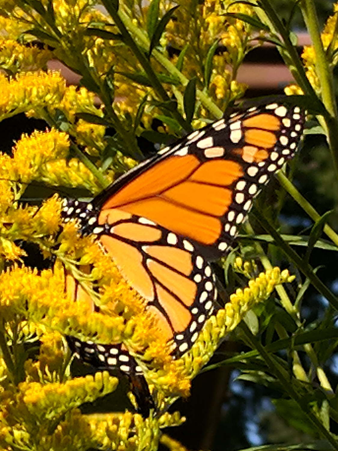
One pair of wasps built this impressive structure behind the patio door, beside the bathroom window:
Organ Pipe Mud Dauber Wasp Nest – side view
The female wasp built six tubes over the course of an August week, carrying blobs of mud the size of her head and abdomen from sources about 30 seconds away (1 minute round trip). Each blob produces half of one serration around the tube, with a seam running down the middle, and requires 20 seconds to smooth into place. We got tired just watching her!
Each tube has many compartments, each containing a wasp larva and a paralyzed spider, with a mud cap inside the end:
Organ Pipe Mud Dauber Wasp Nest – bottom view B
We watched the wasps attack, sting, and remove spiders of a specific size from the corners of our window frames.
The young wasps in the innermost tube may not make it out alive, because they must chew through at least one outer tube before flying away:
Organ Pipe Mud Dauber Wasp Nest – bottom view A
Perhaps layering the outer tubes around a central tube makes for a more compact and durable nest, with the possible sacrifice of offspring in the center.
So it’s not unusual to ride under a small plane on final approach. Having a Gulfstream V fly directly overhead, however, is a real attention-getter:
Gulfstream V on final – Maloney Rd – 2018-08-26
What’s not at all obvious from the picture is how big a GV looks when seen directly overhead through those trees just ahead on the corner where our paths crossed. There’s a 360 ft (above sea level) hill directly on the flight path, so it’s at maybe 600 ft ASL and 400-ish ft AGL.
Thrust-reversal thunder rolled over us 50 seconds later, as we rode up the rail trail access ramp. Figuring we’re 15 sound-seconds from the strip, the GV was 30 seconds from touchdown.
Not much to my surprise, my hack-job thermistor rebuild went bad:
M2 – thermistor – assembly 2
Having nothing to lose, I heated the brass tube over a butane flame to wreck the epoxy, which blew out with a satisfactory bang and filled the Basement Laboratory with The Big Stink.
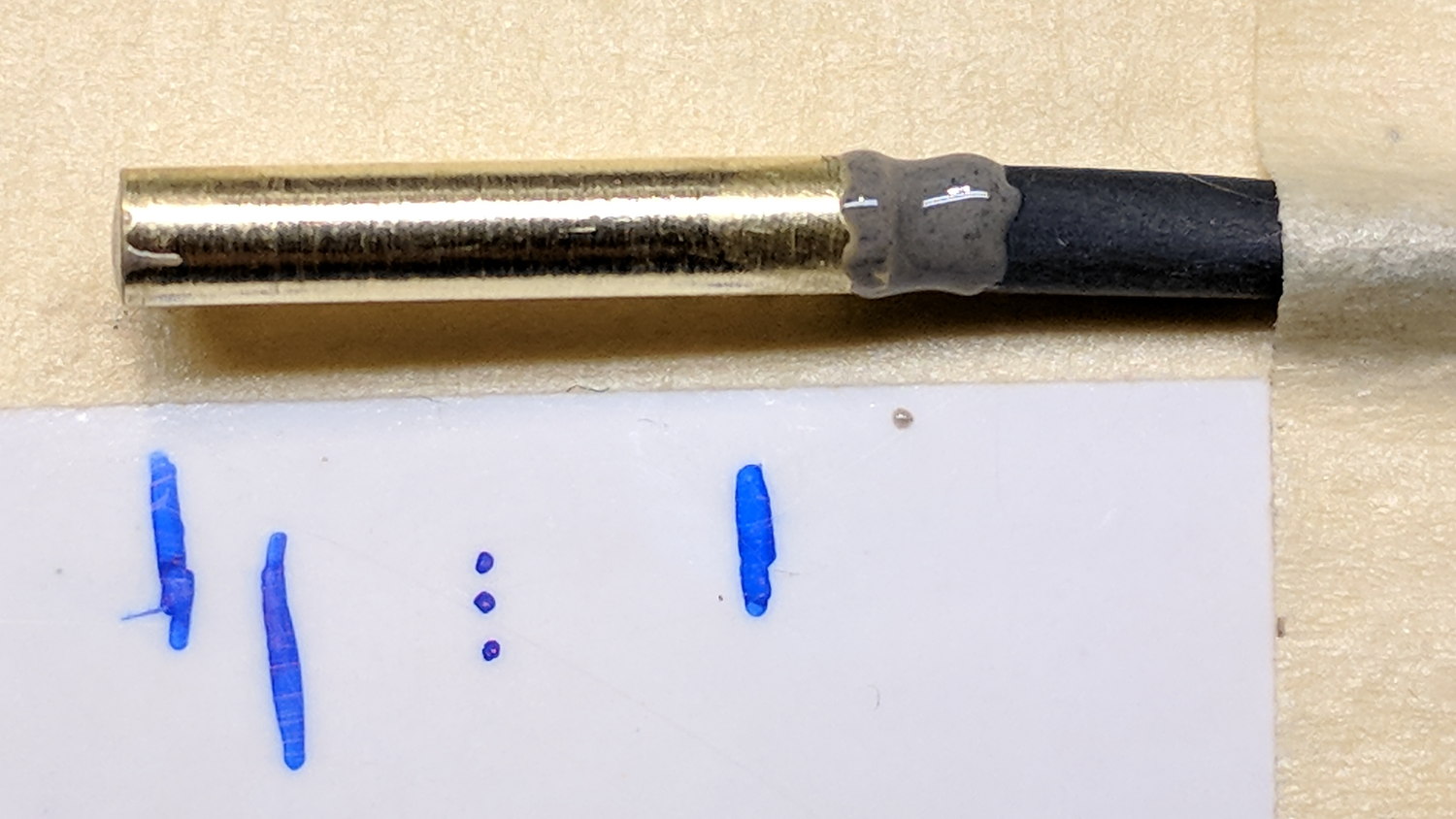
Much to my surprise, the active ingredient still worked:
M2 DIY thermistor corpse
The multimeter reported absolutely no intermittent dropouts for as long as I was willing to watch the trace while doing other things:
DIY Thermistor Autopsy – Resistance Trend
So it must be my crappy soldering technique.
A brace of real M2 thermistors will arrive shortly …
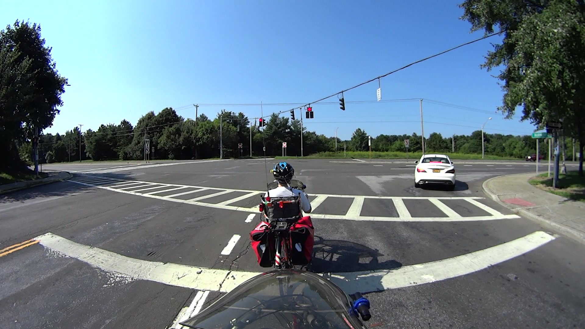
We’re waiting at the end of Burnett Blvd, with the signal red and the clock at T = -0.17 seconds (photo numbers in 1/60 second frames):
RedRunner-0194
You can’t hear the car (barely visible) approaching on the far left, but we can.
T = 0.00 – We get a green light and the (more visible) car is accelerating hard:
RedRunner-0204
T = 1.00 – The car reaches the crosswalk:
RedRunner-0264
Note that the driver of the car to our right isn’t moving, either.
T = 2.03 – Car passes through intersection:
RedRunner-0326
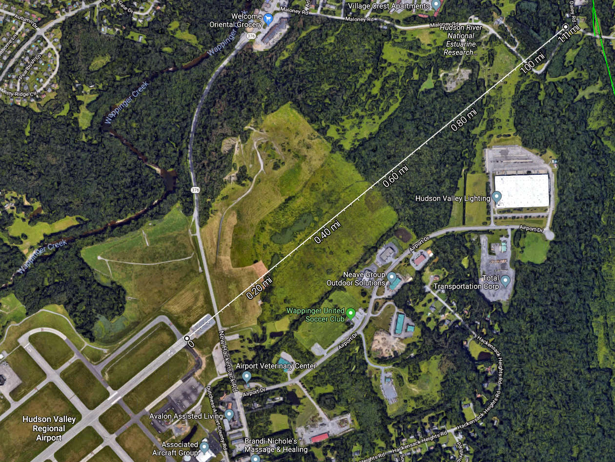
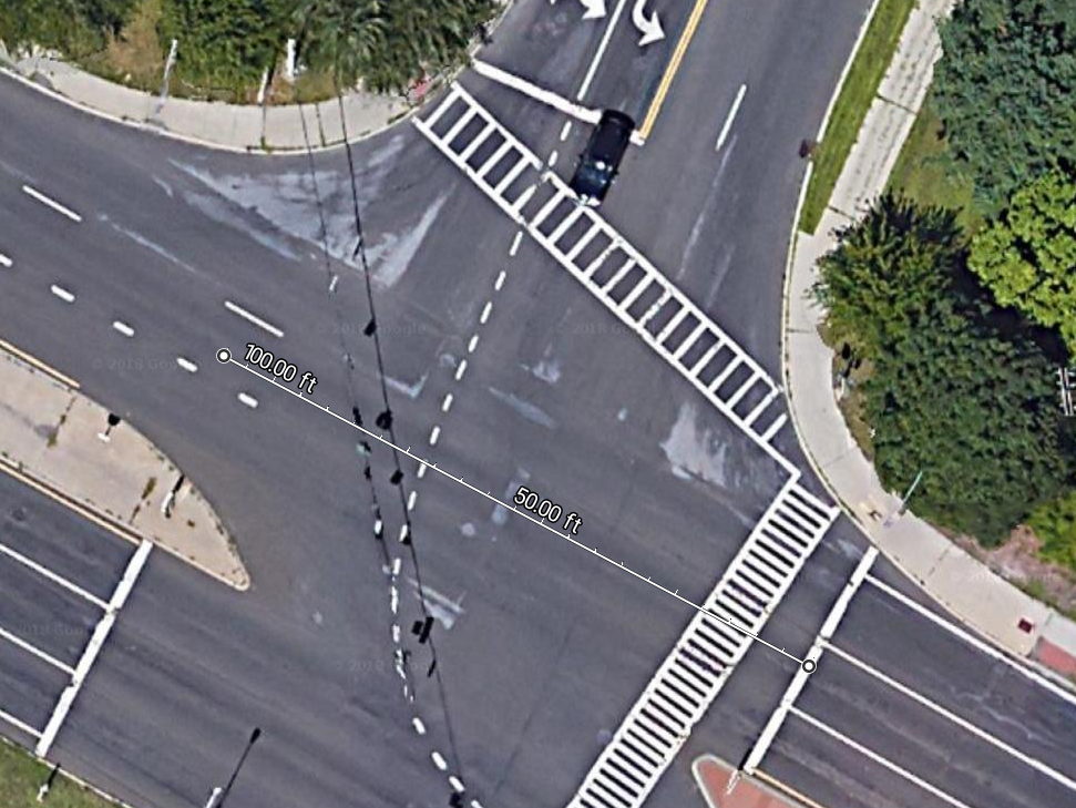
The view from above, showing the distance between those two positions is 100 feet:
Burnett at Rt 55 – Distance along Rt 55
Do the math: 100 ft / 1.03 s = 97 ft/s = 66 mph.
There’s a reason we don’t start moving instantly when a traffic signal turns green.
T = 3.17 – We start moving, as does the car to our right, with our signal still green:
RedRunner-0394
T = 4.88 – Whoops, our signal turns yellow:
RedRunner-0497
T = 9.28 – Our signal turns red:
RedRunner-0761
The signal timing hasn’t changed over the years:
Green = 4.88 s
Yellow = 4.40 s
Elapsed time from green to red: 9.28 seconds. No problem if you’re a car, death if you’re a bike.
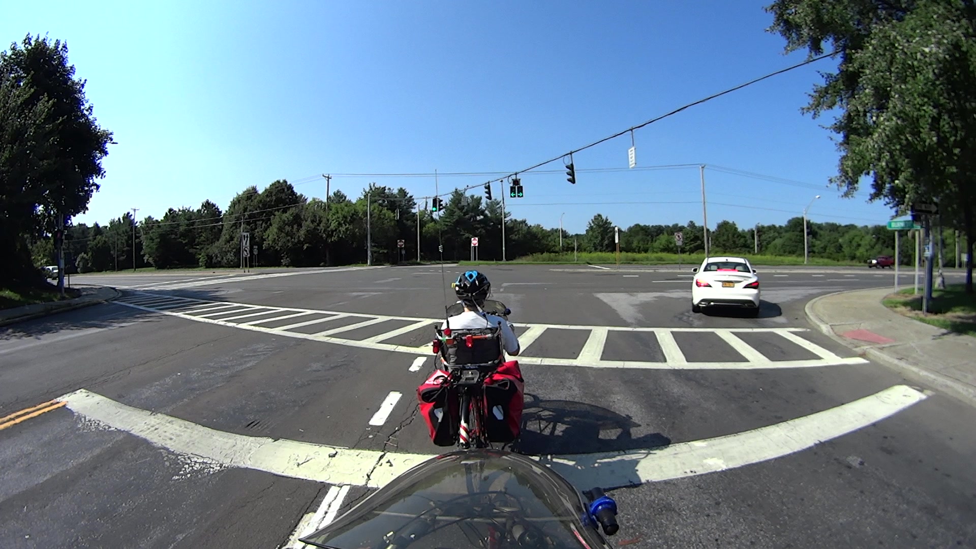
T = 10.42 – We’re pedaling hard in the intersection:
RedRunner-0829
The white car to our far right started moving into the intersection about the time we did. If you’re going to say we shouldn’t run the light, you gotta deal with cars first, OK?
Note the car approaching from the right on the far side of Rt 55. That’s a 40 mph zone, the driver sees a green light, and we’re still in the intersection.
T = 12.50 – We’ve been moving for 9.33 s, which puts Mary directly in the path of the oncoming car:
RedRunner-0954
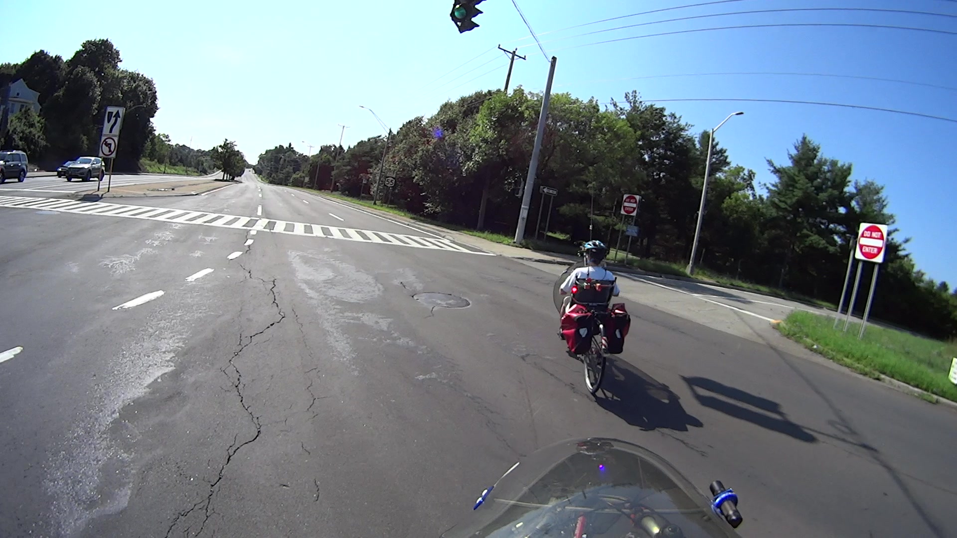
T = 14.83 – The oncoming driver having spotted us and slowed down, we’re asymptotically approaching the right-hand lane of Rt 55, passing beyond the steel manhole cover:
RedRunner-1067
If you plunk “burnett signal” into the search box at the upper right, you’ll find plenty of previous incidents along these lines.
Despite bringing this hazard to their attention many times (“We appreciate and share your interest in making our highway systems safe and functional for all users.“), NYS DOT obviously doesn’t care.
If any of their employees commuted to their office building (which overlooks this very intersection), perhaps they would care, but they don’t: we have yet to see a bicycle in the DOT’s token bike rack.
DOT says they’re in favor of Complete Streets, but, seven years on, it’s just another day on the only route between Arlington and the Overocker Trailhead of the Dutchess County Rail Trail.